1
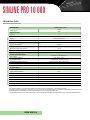
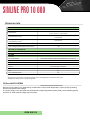
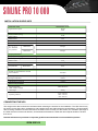
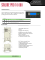
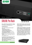
PRODUCT CHARACTERISTICS
SINLINE PRO 10 000
The latest series of the state-of-the-art LINEINTERACTIVE (VI) UPS units is designed to work with
devices powered from a ~230V single-phase grid: servers,
computer networks and data processing systems. SINLINE
PRO 10000 UPS units are available in the Tower version
only. Optional external battery packs can be connected. It is
enough to report the requirement to the manufacturer.
COMMUNICATION
- RS 232,USB communication interface
- SNMP/HTTP Network Management Card (option)
PROTECTION
FEATURES
- Overload protection
- Short-circuit protection
- Thermal protection
- Output voltage filtering
- energy efficiency of 98%;
SUPPORT
- the unique Clear Digital Sinus (CDS) System;
- the Automatic Voltage Regulation (AVR) System;
- Cool Battery Charging (CBC) System.
- On-site support
- 2-year guarantee
- Delivery in 14 business days
ADDITIONAL OPTIONS
-Additional year of warranty at 15% of the
equipment price
www.ever.eu
SINLINE PRO 10 000
TECHNICAL DATA
SINLINE PRO 10 000
PARAMETERS
Output power
10 kVA
8 kW
1)
GENERAL DATA
Topology
VI
Note: The manufacturer reserves the right to modify the above parameters without prior notice.
Total efficiency for Pmax AC/AC
Cooling
>98 %
Forced, internal fans
IP20
Protection level
Work environment
Separate room with low contamination level
Working temperature 2)
10÷400C
Storage temperature
0÷40 C
Relative humidity when working
< 95 %
0
Relative humidity during storage
Altitude above sea level 3)
< 95 %
< 1000 m
POWER NETWORK MODE
~150÷280 V (~165÷280 V)± 2 %
Input voltage
45 ÷ 55 Hz ± 1 Hz
Input voltage frequency
Input voltage range
~172,5÷252 V (~190÷252 V)± 2 %
Switching thresholds: mains-ups
Output voltage waveform
~150 V/~290 V (~165 V/~280 V) ± 2 %
The same as the input
Output voltage filtering
RFI/EMI interference filter, varistor muffler
BATTERY MODE
Output voltage (RMS)
~230 V ± 2 %
Output voltage waveform
Sine
Output voltage frequency
Synchronous / 50Hz ± 0.2 Hz
Switching thresholds: Ups-mains
Output voltage filtering
~155 V/~285 V (~170 V/~275 V) ± 2 %
LC
Output voltage distortion THDu
Crest factor CF
< 5 % for Pmax (line)
2:1
>4:IN
Short circuit current
Notes:
1)
For standard operation, the load that is applied to the output must not exceed 80% of the value in the table.
The power margin is necessary to ensure the continuous work of the connected devices in the case of instantaneous surges of the load.
2)
Constant exposure of the battery module to temperatures of +25°C reduces the battery life.
3)
The permitted maximum load of the power supply unit decreases with the height above the sea level above the limit specified above.
www.ever.eu
SINLINE PRO 10 000
Note: The manufacturer reserves the right to modify the above parameters without prior notice.
TECHNICAL DATA
BATTERIES
Battery voltage (total)
336 VDC
1 x 28 x VRLA 12 V / 7 Ah
UPS batteries
2 x 28 x VRLA 12 V / 7Ah (option)
Internal battery backup time
(100%/80%/50% Pmax)5)
>7/10/15 min
>13/17/30 min
Backup time with 1 battery pack
(100%/80%/50% Pmax)5)
>40/51/92 min
Maximum charging time for internal batteries 4)
< 2h
Maximum charging time for 1 pack
(after recharging with the power of 80% Pmax) 4)
< 3h
MECHANICAL PARAMETERS
Dimensions (width x depth x height)
340x740x795mm
200 kg
UPS weight
FITTINGS
Terminals
Screw terminals; max. 16 (wire)
AC Input protection
Overcurrent switches for base and BYPASS lines 2 x 63 A (eh. B)
DC protection (internal batteries)
30A / 400VDC, cylindrical 10x38 gRB
DC protection (external battery pack)
30A / 400VDC, cylindrical 10x38 gRB
Electronic
Output protection
Sound and LED, LCD display
Signals
Communication interface
RS 232, USB, network management card SNMP / HTTP -option
EPO
yes
Service BYPASS switch
yes
Notes:
4)
Charging time to reach 90% of the battery capacity, prior to discharging with a load equal to 80% Pmax
Example of a battery pack in a typical configuration.
5)
CDS and AVR SYSTEM
Devices from the Sinline Pro 10000 family are fitted with a unique Clear Digital Sinus system (CDS) generating
accurate sinusoidal output voltage.
The power supply unit is also fitted with the Automatic Voltage Regulation system (AVR), which enables lightning
correction of small network voltage drops and rises.
www.ever.eu
SINLINE PRO 10 000
INSTALLATION GUIDELINES
SINLINE PRO 10 000
Parameter / UPS
10 kVA
8 kW
Apparent/active power
Power supply parameters
Supply system topology
1P3W
Rated voltage
230 V
Rated current
46 A
Rated input frequency
50 Hz
Minimum wire section surface area
10mm2
P r i m a r y
and BYPASS
line protection
Switch fuse
80 A gG
Switch fuse
80 A gG
Output parameters
Output system topology
1P3W
Rated output voltage
230 V
44 A
Rated current
Minimum wire section surface area
Output
line protection
Switch
disconnector
10mm2
80 A
Environmental parameters
Quantity of heat released for nominal
work conditions
<600 BTU
Working temperature
10÷400C
Storage temperature
0÷400C
Humidity
< 95 %
Altitude (above sea level)
< 1000 m
Mechanical parameters
Device dimensions
(width x depth x height)
340x740x795mm
200 kg
UPS weight
front: >200 mm
sides: >100 mm
rear: >300 mm
Operating distance
CONNECTING THE UPS
The weight of the device should be considered when selecting the location for the installation. The UPS should only
be used in rooms where dust, temperature, and humidity levels are within the device specifications. The appropriate
device cooling conditions must be ensured for the UPS to work correctly. For this reason, the ventilation openings of
the UPS must be uncovered at all times, and the distance between the UPS and other objects should not be less
than 30 cm.
Detailed information is provided in a separate guidelines document that is enclosed with the product.
www.ever.eu
SINLINE PRO 10 000
PROTECTION
Overload protection
An overload (above 105%) is indicated by a continuous sound and a corresponding message on the display.
If the overload is 105 ÷ 120%, then the power supply unit will remain in the previous mode for one minute before switching
to BYPASS. If the overload exceeds 120% of the nominal power rating, the Bypass mode is switched on immediately. The
unit remains in BYPASS as long as the overload continues above the predefined limit (CONFIGURATION 3/4;
ProgKas.Prz.). Once the overload discontinues, the unit attempts to restart five times. If they fail, the unit switches to
EMERGENCY mode. In BACKUP mode, an overload causes the unit to switch to EMERGENCY mode without any
additional attempts to restart.
Short circuit protection
In the inverter-based modes, i.e. NORMAL, BACKUP, and HYBRID, there is an electronic short circuit protection that, in
case of a short circuit, limits the short circuit current to a safe level. The presence of a short circuit is indicated by the
corresponding message and a quick, intermittent sound. If the short circuit lasts longer than 100 ms, the unit is switched to
EMERGENCY mode. In work modes where the BYPASS line is used, automatic fuses F3 are used.
Surge protection
The unit features surge protection at the input, which protects the receiver circuits and internal circuitry against high
energy voltage surges that are caused by atmospheric phenomena and interference in the power network.
Battery protection
Batteries are protected with fusible cut-outs. The connection of the external battery pack features an additional
safeguard, as do the internal batteries. These safety devices also serve as disconnecting switches that can be used, for
example. during assembly. The types of fuses are specified in the technical parameters table.
!
NOTE! It is forbidden to use fuses other than those listed in the device specification.
The instructions placed in the frame, below the fuses, informing about the need to maintain an
appropriate order when switching in fuses, must be followed. Switch on F1 at the beginning, and then
wait 10 s and switch F2. Failure to follow these instructions may damage the unit.
The fusible cut-out F5 protects the terminal of the external battery pack and is located to the right of the
terminals. When the mounting is open, both poles become disconnected.
Thermal protection
The unit is equipped with a thermal safeguard that protects it against overheating. There are two levels of protection. If the
internal temperature approximates a critical value, then a sound is emitted and a message is displayed on the screen.
The unit remains in the current mode. If the temperature keeps rising, at the critical value an alert message is displayed
and the unit switches to EMERGENCY mode.
www.ever.eu
SINLINE PRO 10 000
USER INTERFACE
The user interface is a four-button keypad on the upper UPS
casing, LCD and three LEDs. It enables the monitoring of
operating parameters and their modification.
Graphical
symbol
AVR
Signal
description
LED1
LED indicating UPS work mode: REGULAR/BACKUP
LED2
LED indicating the activation of the AVR System.
LED3
LED indicating emergency mode
BACK PANEL
1) BYPASS switch cover
2) Fans
3) Adapter card slot plug
4) USB communication interface
5) RS232 communication interface
6) EPO connector
7) Internal battery fuse link
8) Terminal connectors cover
9) AC Input automatic fuses
10) Wire mounting grip
11) BYPASS/UPS service switch
12) Connection panel
13) External battery fusible cut-out
14) Device earthing point
15) Assembly fixtures
www.ever.eu
SINLINE PRO 10 000
USB AND RS232 COMMUNICATION
SINLINE PRO 10000 series units are equipped with extended management functions. There are two RS232 and
USB communication ports and PowerSoft Personal software provided with the UPS. To ensure correct
communication, it is necessary to connect the UPS to a free computer port with the provided communication
cable. Once connected, the UPS and computer should be switched on and the software should be installed as
per the enclosed manual and by following the installation application's instructions (applies to Microsoft
Windows).
SNMP/HTTP NETWORK MANAGEMENT CARD
The EVER network management card is optional and can be installed by the user. It is a device that is used to
integrate the UPS with an Ethernet-type computer network. The network card is located in the special slot on the
back wall of the UPS. The card enables the user to manage the UPS from any computer in the network. This
solution is most often used for central power supply, or if there is a need to manage the power supply system
remotely. The management card features the following services:
SNMP agent enables power supply management with software called
SNMP manager;
HTTP server enables the display and modification of the UPS parameters by using a web Browser;
!
NOTE! A connected SNMP card enables UPS communication with RS232, USB, and
PowerSoft Personal.
EPO
EPO (Emergency Power Off) is a mechanism that cuts off the energy supply to receivers at the UPS output in
extreme situations (e.g. a fire). The unit switches to EMERGENCY mode.
The mechanism can be activated in two ways:
- disconnected pins of the external EPO connector (release device),
- manual command on the interface (CONTROL 1/3; EmergencyShut-down).
The output voltage will be circuited again after the user commands the cancellation of the alert flag (CONTROL
2/3; EraseFailure) and sets the release device to inactive (normal position) - in case of the external initiation of the
release. It is possible to temporarily lock the EPO function during the assembly of the EPO release device. Then,
the technician can remove the EPO connector without risking a blackout of the receiver devices. It may last up to 1
minute, beginning from the setting of the control flag (CONTROL 2/3, Shut-down time.EPO). After that time, the lock is
automatically turned off.
SERVICE BYPASS SWITCH
The unit is equipped with a service BYPASS line switch, which enables the direct
switching of the BYPASS line to connect it to the output clips of the unit and
bypassing the unit blocks.
www.ever.eu
SINLINE PRO 10 000
CONNECTION TERMINALS
F3
F4
Service BYPASS line protection
Primary line protection
WEJ AC
LB
L
N
input terminals
service BYPASS phase line
primary phase line
primary neutral line
WYJ AC
L
N
output terminals
output phase line
output neutral line
WEJ DC
+
-
input terminals for the external battery pack
red pole
blue pole
F5
protection for the external battery pack terminal (fuse- link)
protective earthing point, connection of a cable with an eyehole connector using an M6 screw
The UPS is not provided with connection wires with sockets. Therefore, the connection takes place by
screwing down the ends of the individual conductors to the connector. Then, the conductors need to be
protected against being pulled out with clips that are attached to holders below the connection terminals.
The wire sizes specified in the wiring guidelines should be used. The conductor ends should be finished
with metal sleeves.
-
!
NOTE! The UPS should be connected by qualified and authorised personnel only. The UPS
Is completely disconnected from the power network only when the power supply cord is
disconnected.
It is recommended for the protection systems in the building's electric system to be used as one of the measures of
protection. The parameters of the building's electric wiring system protection should be selected in accordance with
the type and magnitude of the load connected to the wiring system. In extreme cases, the different protection
parameters of the building and power supply unit's systems may cause the former to be activated more rapidly.
EVER Sp. z o.o. ul. Grudziñskiego 30, 62-020 Swarzêdz
tel. 0048 61 6500 400, fax 0048 61 6510 927, e-mail: [email protected]