1
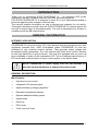
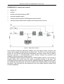
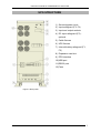
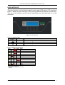
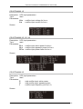
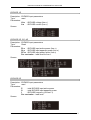
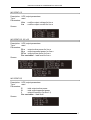
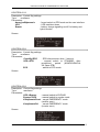
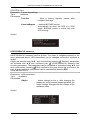
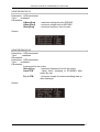
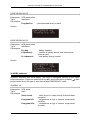
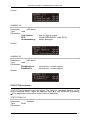
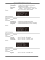
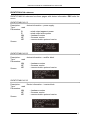
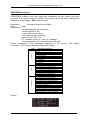
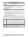
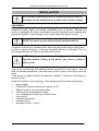
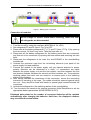
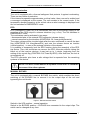
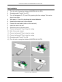
Instruction manual for POWERLINE 33 series UPS
TABLE OF CONTENTS
TABLE OF CONTENTS........................................................................................................................................ 2
INTRODUCTION .................................................................................................................................................. 3
GENERAL INFORMATION ................................................................................................................................. 3
INTENDED APPLICATION............................................................................................................................. 3
GENERAL DESCRIPTION .............................................................................................................................. 3
UPS STRUCTURE ................................................................................................................................................. 5
USER INTERFACE........................................................................................................................................... 6
PAGES ............................................................................................................................................................... 8
Main menu .............................................................................................................................................................. 9
POMIARY submenu............................................................................................................................................... 9
KONTROLA submenu ......................................................................................................................................... 14
KONFIGURACJA submenu................................................................................................................................. 16
ALARMY submenu.............................................................................................................................................. 18
STATYSTYKA submenu ..................................................................................................................................... 19
USTAWIENIA PANELU submenu...................................................................................................................... 21
IDENTYFIKACJA submenu ................................................................................................................................ 22
ZDARZENIA submenu ........................................................................................................................................ 23
HEALTH AND SAFETY ..................................................................................................................................... 24
TRANSPORT................................................................................................................................................... 24
ELECTRICAL SAFETY ................................................................................................................................. 24
INSTALLATION.................................................................................................................................................. 25
UNPACKING .................................................................................................................................................. 25
ASSEMBLY .................................................................................................................................................... 26
BATTERY PACK (optional) ........................................................................................................................... 26
Connection of modules ......................................................................................................................................... 27
Disconnection of modules..................................................................................................................................... 28
CONNECTING THE UPS............................................................................................................................... 29
Connection Terminals ........................................................................................................................................... 29
Electric installation ............................................................................................................................................... 30
START (power from mains) ................................................................................................................................. 31
START (no power from mains) ............................................................................................................................ 31
TURN OFF AND DISCONNECT........................................................................................................................ 32
OPERATION MODES .................................................................................................................................... 32
OTHER FUNCTIONAL COMPONENTS ...................................................................................................... 35
Protection .............................................................................................................................................................. 35
EPO .................................................................................................................................................................. 37
MANUAL BYPASS ........................................................................................................................................ 37
WORK WITH COMPUTERS .............................................................................................................................. 38
USB AND RS232 COMMUNICATION ......................................................................................................... 38
SNMP/HTTP NETWORK MANAGEMENT CARD ..................................................................................... 38
Card installation .................................................................................................................................................... 39
POWERSOFT PERSONAL INSTALLATION AND CONFIGURATION ................................................... 40
Windows ............................................................................................................................................................... 40
Linux/Unix............................................................................................................................................................ 40
Software update .................................................................................................................................................... 41
COMMENTS ON OPERATION.......................................................................................................................... 42
WORK WITH POWER GENERATORS ........................................................................................................ 42
STORAGE, MAINTENANCE, AND TRANSPORT...................................................................................... 43
UTILISATION................................................................................................................................................. 43
TECHNICAL PARAMETERS............................................................................................................................. 44
INSTALLATION GUIDELINES .................................................................................................................... 44
TECHNICAL DATA ....................................................................................................................................... 45
LEGAL REGULATIONS AND THE GUARANTEE ......................................................................................... 46
DECLARATION OF CONFORMITY ............................................................................................................ 46
2010/06/22
www.ever.eu
2
Instruction manual for POWERLINE 33 series UPS
INTRODUCTION
Thank you for purchasing EVER POWERLINE 33 – an advanced UPS series
dedicated to servers, computer networks, and data processing systems.
UPS EVER POWERLINE 33 is designed to meet all of your expectations related to
protection against power outages in the best way.
This manual contains information on how to operate and maintain the unit safely.
Thoroughly familiarise yourself with the EVER POWERLINE 33 manual before the
first use to ensure that it is operated properly. The unit is manufactured in Poland, in
compliance with the CE requirements.
GENERAL INFORMATION
INTENDED APPLICATION
POWERLINE 33 units are on-line (VFI) class devices that are intended to work with
equipment powered from ~230V three-phase mains. POWERLINE 33 units are
dedicated to very sensitive receiver devices. They generate output voltage with
benchmark-quality parameters. The units feature high short-circuit current allowing
for the high selectivity of grid protection. The units are equipped with an event log
that is available to users via the embedded LCD. The unit features high efficiency in
ECO mode and a wide selection of input current options in the hybrid mode.
NOTE! POWERLINE 33 power supply units are not intended for
use with medical equipment to support life and/or health.
GENERAL DESCRIPTION
Main features:
•
High short-circuit current
•
Integrated LCD operator panel
•
Advanced battery charging algorithm
•
Extended management options
•
Optional additional battery packs
•
Hybrid mode
•
Event log
•
ECO mode
•
“Cold” and “soft” start
2010/06/22
www.ever.eu
3
Instruction manual for POWERLINE 33 series UPS
POWERLINE 33 components include:
•
battery set
•
rectifier
•
inverter with high-frequency IGBT
•
automatic bypass (static)
•
manual (service) bypass (UPS/bypass manual switch)
•
microprocessor-based control system with measurement circuits
Figure 1: Simple block scheme
Input rectifier transforms alternating voltage from the input to direct current at the
output, and charges the batteries at the same time. The DC bus is the basic power
source for the inverter that generates alternating sine wave current that is used to
feed the receivers. A microprocessor control system ensures the precision and
reliability of the entire power supply system.
An automated bypass system increases the overall system security. In the event of
inverter failure, the current from the mains is provided directly to the load. The
automated bypass system thus becomes an additional passive safeguard of the load.
An additional manual bypass connection enables the complete switch of the load to
the mains. The receivers are then backed up from the mains with the internal UPS
modules bypassed.
2010/06/22
www.ever.eu
4
Instruction manual for POWERLINE 33 series UPS
UPS STRUCTURE
1) Service bypass circuit
2) Input safeguard (F3, F4)
3) Input and output sockets
4) DC input safeguard (F5) optional
5) Cable fixtures
6) UPS fixtures
7) Internal battery safeguard (F1,
F2)
8) Expansion card slot
9) EPO interface
10) USB port
11) RS232 port
12) Fans
Figure 2: Rear panel
2010/06/22
www.ever.eu
5
Instruction manual for POWERLINE 33 series UPS
USER INTERFACE
The user interface is a four-button keypad on the upper UPS casing, LCD, and three
LEDs. It allows for the monitoring of the working parameters and their modification.
The use of the interface and the specific parameters are described later on in this
document.
Figure 3: User interface
Table 1 Signalling LEDs
Graphical
Symbol
symbol
LED 1
LED 2
LED 3
Description
LED indicating UPS work mode: NORMAL/BACKUP
LED indicating the activation of BYPASS
LED indicating the EMERGENCY mode
Table. 2 Visual signals (LEDs)
LED 1
LED 2 LED 3 Mode
UNKNOWN
F
NORMAL
ECO
F
BYPASS
BACKUP
F
STANDBY
F
E
*
*
SUSPENDED
*
EMERGENCY
F
INIT
F
STOP
HIBRID
E – if EPO is started, then signals are turned off. Otherwise, emergency
mode signalling is turned on.
F – depends on configuration (none or red).
* - blinking
2010/06/22
www.ever.eu
6
Instruction manual for POWERLINE 33 series UPS
The unit also features sound alarms corresponding to the specific operational modes
(table).
Table. 3 Sound alerts
Event
REGULAR
HIBRID
BACKUP
Sound
None
beeps that accelerate as the batteries empty until the sound becomes continuous
Forced STANDBY
two short beeps and a pause
EMERGENCY
depending on the type of event
OVERLOAD
continuous sound
Short circuit
short beeps and pauses (50/50)
Overheating
slow beeps and pauses (50/50)
EPO start
beeps and pauses (1 sec./5 sec.)
All LCD pages are based on a tree hierarchy shown in the below figure.
Figure 4: LCD page hierarchy
2010/06/22
www.ever.eu
7
Instruction manual for POWERLINE 33 series UPS
PAGES
SCREENSAVER
Description: Information page that appears as a screensaver after 5 minutes of the
last button being pressed. It turns off LCD illumination, as well.
Type:
read
Parameters:
Q
- battery charge level
U+
- hot battery cell (+) voltage
U- cold battery cell (-) voltage
Owy
- battery load level
Tau
- expected backup duration
TrybPracy - operation mode
i: …, A: … - additional information according to the table
General messages (i:) describe all the operation modes, except for
EMERGENCY, which is signalled with emergency messages
General messages
Alerts
Abbreviation
Power supply
Message
Description
i:Ladowanie
Charging
A:Zwarcie
Short circuit F)
i:PrzeciąŜenie
Overload
A:PrzeciąŜenie
Overload F)
i:PrzegrzanieProst
Rectifier block overheating
A:PrzegrzanieProst
Rectifier block overheating P)
i:PrzegrzanieFal
Inverter block overheating
A:PrzegrzanieFal
Inverter block overheating F)
i:OczekNaLadunekMin
Waiting after STANDBY
A:UszkAkumulatora
Damaged batteries P)
i:AkumulatorRozlad
90 s backup time left
Periodic servicing
recommended
BYPASS active
No communication with
rectifier block
No communication with
inverter block
Incorrect phase order in
BYPASS
Exceeded BYPASS
parameters
Open battery circuit
Exceeded inverter block
parameters
A:EPO
Emergency EPO F)
A:BladWewProstownika
Internal rectifier block error P)
A:BladWewFalownika
Internal inverter block error F)
i:Serwis
i:Bypass
i:BrakKomProst
i:BrakKomFal
i:ZlaKolejnoscFazByp
i:ZasBypPozaZakres
i:OtwartyObwAku
i:ZasProstPozaZakres
F) message started by KasujAwarieFal
(Configuration 3/4)
P) message ended by KasujAwarieProst
(Configuration 3/4)
Screen:
2010/06/22
www.ever.eu
8
Instruction manual for POWERLINE 33 series UPS
Main menu
The main menu has three pages. The pages are navigated by pressing the ▼▲
buttons. Items are selected by pressing . Once selected, a submenu appears that
can be navigated by using ▼▲.
The arrow on the left side of the submenu name shows the current position. The
selection must be confirmed by pressing . ESC moves one level up.
POMIARY submenu
The POMIARY submenu has two pages with five thematic groups: PROSTOWNIK,
BYPASS, WYJSCIE, AKUMULATOR, TEMPERATURA. The menu is navigated
similarly to the menu presented above.
2010/06/22
www.ever.eu
9
Instruction manual for POWERLINE 33 series UPS
PROSTOWNIK 1/5
Description: UPS input parameters
Type:
read
Parameters:
ULn - rectifier input voltage for line n
ILn - rectifier input current for line n
Screen:
PROSTOWNIK 2/5, 3/5, 4/5
Description: UPS input parameters
Type:
read
Parameters:
PLn - rectifier input active power for line n
SLn - rectifier input apparent power for line n
PFLn - rectifier input power factor for line n
Screen:
PROSTOWNIK 5/5
Description: UPS input parameters
Type:
read
Parameters:
P
- total rectifier input active power
S
- total rectifier input apparent power
f
- rectifier input frequency (for line L1)
Screen:
2010/06/22
www.ever.eu
10
Instruction manual for POWERLINE 33 series UPS
BYPASS 1/5
Description: BYPASS input parameters
Type:
read
Parameters:
ULn - BYPASS voltage (line n)
ILn - BYPASS current (line n)
Screen:
BYPASS 2/5, 3/5, 4/5
Description: BYPASS input parameters
Type:
Read
Parameters:
PLn - BYPASS input active power (line n)
SLn - BYPASS input apparent power (line n)
PFLn - BYPASS input power factor (line n)
Per cent value – load level for line n.
Screen:
BYPASS 5/5
Description: BYPASS input parameters
Type:
read
Parameters:
P
- total BYPASS input active power
S
- total BYPASS input apparent power
f
- BYPASS frequency (for line L1)
Per cent value – load level
Screen:
2010/06/22
www.ever.eu
11
Instruction manual for POWERLINE 33 series UPS
WYJŚCIE 1/5
Description: UPS output parameters
Type:
read
Parameters:
ULn - rectifier output voltage for line n
ILn - rectifier output current for line n
Screen:
WYJŚCIE 2/5, 3/5, 4/5
Description: UPS output parameters
Type:
read
Parameters:
PLn - output active power for line n
SLn - output apparent power for line n
PFLn - output power factor for line n
Per cent value – load level for line n.
Screen:
WYJŚCIE 5/5
Description: UPS output parameters
Type:
read
Parameters:
P
- total output active power
S
- total output apparent power
f
- output frequency (for line L1)
Per cent value – load level
Screen:
2010/06/22
www.ever.eu
12
Instruction manual for POWERLINE 33 series UPS
AKUMULATOR 1/2
Description: Battery parameters
Type:
Read
Parameters:
U+
- hot battery cell (+) voltage
U- cold battery cell (-) voltage
I+
- absolute value of battery current in hot (+) block
I- absolute value of battery current in cold (-) block
Q
- current battery charge (based on current load)
Tau - expected backup duration
Screen:
AKUMULATOR 2/2
Description: Battery parameters
Type:
Read
Parameters:
StanAku.
- battery capacity level; the value is updated after
complete discharge, if TestAku is on; 100% (default)
means full capacity of batteries
Screen:
TEMPERATURA 1/1
Description: Temperature parameters - temperature of internal UPS components
Type:
read
Parameters:
T0, T1, T2, T3
- temperature of internal UPS components
Screen:
2010/06/22
www.ever.eu
13
Instruction manual for POWERLINE 33 series UPS
KONTROLA submenu
KONTROLA submenu has four groups. The menu is navigated similarly to the menu
presented above. UPS configuration can be changed, however the change of a given
parameter depends on certain conditions. See the table below.
X
Czas.Wyl.EPO
X
UPS->STB/STB->UPS
□
□
X
X
X
ECO
X
X
UPS->Bypass/Bypass-UPS
X
KasujAwarie
X
TestAku
X
KontrolaBypass
X
EMERGENCY
Buzzer
BYPASS
X
STANDBY
X
●
○
□
□
STOP
UPS
●
○
□
□
ECO
●
BACKUP
X
HYBRID
Flag
AwaryjneWylaczenie
NORMAL
INIT
UNKNOWN
Mode
SUSPENDED
Fig. 4 Control flag changes
●
○
□
□
● ●
● ■
□ □
□ □
●
○
□
□
●
○
□
□
□
□
X
●
○
□
□
●
X
X
X
X
X
X
X
X
X
X
□
□
X
X
X
X
●
●
●
●
X
X
X
○
X
X
X
X
X
X
X
X
X
X
□
□
□
□
□
□
□
●
□
X
X
X
□
□
□
X
□
□
X
X
X
X – no change permitted
● – turn on only
○ – turn off only
□ - switch
■ – turn on only; turn off only when
waiting for minimal charge
X
X
Note! ECO flag on in turn
causes the automatic
setting of the
KontrolaBypass flag
Pages are selected using ▲▼, and confirmed by pressing
. Similarly, the
parameters are selected with ▲▼ and confirmed with . KONTROLA submenu has
two types of parameters. Some require an additional confirmation to change (press
) or cancellation without change (press ESC), e.g. AwaryjneWylaczenie. Others
are changed by selecting Wl or Wyl with the flag, using ▲▼, and confirmed by
pressing . Once confirmed, the page moves up one level in the tree.
A confirmed parameter is saved in the UPS memory. Saving is signalled with the
following messages:
-- Trwa zapis --- Zapis OK --- Blad zapisu --- Zla wartość --
- saving in progress
- saved successfully
- not saved, try again
- parameter exceeds the permitted level
The messages are displayed briefly at the bottom of the page, and then the page
moves up one level. That rule applies to all changed parameters.
2010/06/22
www.ever.eu
14
Instruction manual for POWERLINE 33 series UPS
KONTROLA 1/4
Description: Control flag settings
Type:
read/save
Parameters:
AwaryjneWylaczenie
- forced switch to EPO mode on the user interface
UPS
- UPS start/shut down
Buzzer
- battery charge signalling on/off for battery and
hybrid modes
Screen:
KONTROLA 2/4
Description: Control flag settings
Type:
read/save
Parameters:
Czas.Wyl.EPO
- EPO disconnection time (1 minute).
UPS->STB
- manual switch to STANDBY; after
predefined
period
(KONFIGURACJA
2/4;Opoz.STB)
ECO
- switch to ECO mode
Screen:
KONTROLA 3/4
Description: Control flag settings
Type:
read/save
Parameters:
UPS->Bypass
- manual switch to BYPASS
Bypass->UPS
- manual switch to regular mode
KasujAwarieProst - cancel EMERGENCY mode
(rectifier error)
KasujAwarieFal
- cancel EMERGENCY mode
(inverter error)
Screen:
2010/06/22
www.ever.eu
15
Instruction manual for POWERLINE 33 series UPS
KONTROLA 4/4
Description: Control flag settings
Type:
read/save
Parameters:
Test Aku
- allow a battery capacity update after
complete discharge
KontrolaBypass
- start/end BYPASS control:
automatically on when the UPS is in ECO
mode; BYPASS control is active only with
UPS running.
Screen:
KONFIGURACJA submenu
KONFIGURACJA submenu has five groups. The menu is navigated similarly to the
menu presented above. UPS parameters can be changed, unless the keyboard is
locked.
Pages are selected using ▲▼, and confirmed by pressing . Similarly, parameters
are selected with ▲▼ and confirmed with
. KONFIGURACJA submenu has
numeric parameters. The parameters can be increased or decreased using ▲▼, and
then confirmed by pressing . Once confirmed, the page moves up one level in the
tree. A given change of a parameter can be cancelled by pressing ESC.
KONFIGURACJA 1/5
Description: UPS parameters
Type:
read/save
Parameters:
UWyLn
- output voltage for line n; after changing the
parameter during inverter-based operation, the
output voltage changes with the change of the
operation mode
Screen:
2010/06/22
www.ever.eu
16
Instruction manual for POWERLINE 33 series UPS
KONFIGURACJA 2/5
Description: UPS parameters
Type:
read/save
Parameters:
UGornyProg
- maximum voltage limit for BYPASS
UDolnyProg
- minimum voltage limit for BYPASS
fDolnyProg
- minimum frequency limit for main
Screen:
KONFIGURACJA 3/5
Description: UPS parameters
Type:
read/save
Parameters:
Description: UPS parameters
Type:
read/save
Parameters:
frequencies for the mains
fGornyProg
- maximum frequency limit for the mains
Opoz.STB
- delay when changing to STANDBY after
switch by user
Poj. z STB.
- minimum charge of batteries enabling start up
after discharge
Screen:
2010/06/22
www.ever.eu
17
Instruction manual for POWERLINE 33 series UPS
KONFIGURACJA 4/5
Description: UPS parameters
Type:
read/save
Parameters:
ProgKas.Prz.
- permitted load level (no alert)
Screen:
KONFIGURACJA 5/5
Description: UPS parameters
Type:
read/save
Parameters:
Poj.Aku.
LiczbaSekcji
Pr.Ladowania
- battery capacity
- number of battery blocks (total internal and
external cells)
- total battery charge current
Screen:
ALARMY submenu
ALARMY submenu has three pages. The menu is navigated similarly to the menu
presented above. Pages are selected using ▲▼, and confirmed by pressing . Alert
pages inform about the type of alert that caused EMERGENCY mode.
ALARMY 1/3
Description: UPS alerts
Type:
read
Parameters:
Short circuit
PrzegrzaniePr
PrzegrzanieFal
2010/06/22
- short circuit in output during inverter-based
operation
- temperature to high in internal components
(rectifier)
- temperature to high in internal components
(inverter)
www.ever.eu
18
Instruction manual for POWERLINE 33 series UPS
Screen:
ALARMY 2/3
Description:
UPS alerts
Type:
read
Parameters:
Przeciazenie
EPO
AkuUszkodzony
- load too high at output
- forced EMERGENCY mode (EPO)
- battery damaged
Screen:
ALARMY 3/3
Description:
UPS alerts
Type:
read
Parameters:
BladWewProst
BladWewFal
Screen:
- internal error, contact support
- internal error, contact support
STATYSTYKA submenu
STATYSTYKA submenu has four pages. The menu is navigated similarly to the
menu presented above. Pages are selected using ▲▼, and confirmed by pressing
. The pages show information on the history of operation.
STATYSTYKA 1/4
Description:
Statistics
Type:
Read
Parameters:
2010/06/22
www.ever.eu
19
Instruction manual for POWERLINE 33 series UPS
Niepraw.Siec
Przeciazen
Zwarc
- number of events related to the incorrect
parameters of the mains
- number of events related to UPS overload
- number of events related to output short
circuit during inverter-based operation
Screen:
STATYSTYKA 2/4
Description:
Statistics
Type:
Read
Parameters:
Rozladowan
- number of complete discharge events
PrzegrzProst - number of events related to rectifier overheating
PrzegrzFal
- number of events related to inverter overheating
Screen:
STATYSTYKA 3/4
Description:
Statistics
Type:
Read
Parameters:
Przeciaz
- period of operation with overload
Normalna
- period of operation in NORMAL mode
Rezerwowa
- period of operation in BACKUP mode
Screen:
STATYSTYKA 4/4
Description:
Statistics
Type:
Read
Parameters:
Bypass
- period of operation in BYPASS mode
2010/06/22
www.ever.eu
20
Instruction manual for POWERLINE 33 series UPS
Screen:
USTAWIENIA PANELU submenu
USTAWIENIA PANELU submenu has two pages. The menu is navigated similarly to
the menu presented above. The UPS parameters can be changed, unless the
keyboard is locked.
Similarly, the parameters are selected with ▲▼ and confirmed with . USTAWIENIA
PANELU submenu has numeric parameters. The parameters can be increased or
decreased using ▲▼, and then confirmed by pressing . Once confirmed, the page
moves up one level in the tree. A given change of a parameter can be cancelled by
pressing ESC.
USTAWIENIA PANELU 1/2
Description:
User interface settings
Type:
read/save
Parameters:
Kontrast
- LCD display contract
Podswietlanie
- LCD display brightness
Blok.Kl.
- keyboard lock; changed in the control software
only; parameters cannot be changed when the
keyboard is locked
Screen:
USTAWIENIA PANELU 2/2
Description:
User interface settings
Type:
read/save
Parameters:
Ustawienia czasu - clock settings
Press
to edit. Clock parameters are changed similarly as written
above.
Screen:
2010/06/22
www.ever.eu
21
Instruction manual for POWERLINE 33 series UPS
IDENTYFIKACJA submenu
IDENTYFIKACJA submenu has three pages with device information. ESC exits the
menu.
IDENTYFIKACJA 1/3
Description:
device information – power supply
Type:
read
Parameters:
S
- rated output apparent power
P
- rated output active power
VH
– hardware version
VF
– firmware version
VP
– communication protocol version
Screen:
IDENTYFIKACJA 2/3
Description:
device information – rectifier block
Type:
read
Parameters:
VH
– hardware version
VF
– firmware version
VP
– communication protocol version
Screen:
IDENTYFIKACJA 3/3
Description:
Device information – inverter block
Type:
read
Parameters:
VH
– hardware version
VF
– firmware version
VP
– communication protocol version
Screen:
2010/06/22
www.ever.eu
22
Instruction manual for POWERLINE 33 series UPS
ZDARZENIA submenu
ZDARZENIA submenu has one page with information on the events that have
occurred. The register stores 40 events. Once filled, every new event replaces the
oldest item in the register. ESC exits the menu.
Description:
Information about event history
Type:
Read
Parameters:
The panel displays (in that order):
- record number (1-40)
- event date (<month-day>)
- time (hour:minutes:seconds)
- type of event (TP, A, K)
TP - operation mode, A – alert, K - message
- short description of an event based on the table.
Events correspond to the messages displayed on the screen: “ON” means
occurrence, “OFF” means that the causes have ended.
Messages
Alerts
Mode
TYPE
Abbreviated description
TP NIEZNANY
TP INIT
TP SIECIOWA
TP HYBRYDOWA
TP REZERWOWA
TP ECO
TPSTOP
TP CZUWANIE
TP STANDBY
TP BYPASS
TP AWARYJNA
A ZwarcieOn / ZwarcieOff
A PrzeciazenieOn / PrzeciazenieOff
A PrzegProstOn / PrzegProstOff
A PrzegFalownikOn / PrzegFalownikOff
A UszkAkuOn / UszkAkuOff
A EPOOn / EPOOff
A BlWewProstOn / BlWewProstOff
A BlWewFalownikOn / BlWewFalownikOff
K LadowanieOn / LadowanieOff
K PrzeciazenieOn / PrzeciazenieOff
K PrzegProstOn / PrzegProstOff
K PrzegFalownikOn / PrzegFalownikOff
K OczekNaLadMinOn / OczekNaLadMinOff
K AkuRozladowanyOn / AkuRozladowanyOff
K SerwisOn / SerwisOff
K BrakKomProstOn / BrakKomProstOff
K ZlaKolFazBypOn / ZlaKolFazBypOff
K ZasBypPozaZakrOn / ZasBypPozaZakrOff
K OtwartyObwAkuOn / OtwartyObwAkuOff
K ZasPrPozaZakrOn / ZasPrPozaZakrOff
Screen:
2010/06/22
www.ever.eu
23
Instruction manual for POWERLINE 33 series UPS
HEALTH AND SAFETY
TRANSPORT
•
•
•
exercise particular care when moving;
the device is equipped with rubber wheels due to its significant weight;
the device should be operated and stored in conditions concordant with those
set in the device specification;
ELECTRICAL SAFETY
•
•
•
•
•
it is forbidden to work on your own under conditions constituting a threat to life
and/or health;
in the event of a brief short-circuit, the high current may cause serious burns;
before connecting the device, it is necessary to check the technical condition of
the cables, plugs and sockets, as well as that of the device itself;
if possible, only use one hand when connecting and disconnecting the
communication cables in order to avoid potential electric shock when two
surfaces of the opposite charge touch;
the device must be plugged with a PE protective earthing clip; failure to comply
with this requirement can lead to electric shock;
It is strictly forbidden for the user to perform any repair work, as this would constitute
a threat to health and/or life. All repairs and battery replacements must be carried out
exclusively by qualified service personnel licensed appropriately with the applicable
laws.
NOTE! The UPS is completely disconnected from the power
network only when the power supply cord is disconnected.
The device is equipped with an internal power source (internal
batteries with high potential); dangerous voltage may be present
at the output, even though it may not be connected to the mains.
NOTE! POWERLINE 33 power supply units are not intended for
use with medical equipment to support life and/or health.
2010/06/22
www.ever.eu
24
Instruction manual for POWERLINE 33 series UPS
INSTALLATION
NOTE! Before installing the device, familiarise yourself with the
principles of work safety that are set out in the previous chapter.
UNPACKING
Inspect the power supply unit visually immediately upon its delivery. Although the
product is packaged, the device could have undergone damage due to inappropriate
transport conditions. If any damage is discovered, inform the carrier or seller.
NOTE! The device may be delivered with installed batteries.
The device is placed on a wooden pallet, which may be moved using a forklift truck.
In order to unpack the device, cut through the bands affixing it to the pallet. Then, lift
the cardboard boxes off. Remove the protective corners.
NOTE! Use extra caution when unboxing, as the device has been
specially packed. Falling of the device may cause a threat to
health or life.
If the device is delivered with batteries, please note that it is very heavy – see the
table of technical parameters. Use belts and a hoist to remove the device from the
pallet.
If the device is supplied without the batteries installed, it should be removed by 4
people at least.
Check the contents of the packaging. The packaging should contain the following:
•
•
•
•
•
•
•
•
•
power supply,
PowerSoft Personal software and manual on CD,
RS232 computer communication cable,
USB computer communication cable,
set of safeguard fuse links, type 22x58 (2 pcs),
user manual,
installation guidelines,
guarantee card,
assembly fixtures – (2 pcs)
2010/06/22
www.ever.eu
25
Instruction manual for POWERLINE 33 series UPS
ASSEMBLY
When selecting the place of installation, consider the weight of the device. The UPS
should only be used in rooms where the dust, temperature, and humidity levels are
within the device specifications. Appropriate cooling conditions must be ensured for
the UPS to work properly. For this reason, the ventilation openings of the UPS must
be uncovered at all times, and the distance between the UPS and other objects
should not be less than 30 cm.
NOTE! It is forbidden to install the device near flammable
materials!
Once positioned, use two additional assembly fixtures to increase its mechanical
stability. To do this, loosen the 4 M8 screws located in the central bottom part of the
device. Place the fixtures carefully and screw them to the device by using the
previously removed screws.
Figure 6 Assembly grips
Detailed information is provided in a separate installation guidelines document that is
enclosed with the product.
BATTERY PACK (optional)
POWERLINE 33 units also allow for the connecting of additional battery packs. The
battery packs can be connected to the connection terminal clips at the back panel.
Additional battery packs will extend the battery mode work time. The battery packs
have additional safeguard located on the rear panel.
NOTE! If the safeguard fuse link is damaged, replace it with a new
one that is compliant with the device specification.
2010/06/22
www.ever.eu
26
Instruction manual for POWERLINE 33 series UPS
Figure 1: Battery pack connection
Connection of modules
NOTE! Danger of electric shock! When installing, make sure that
all safeguards are disconnected.
1. Turn the unit off by using the interface (KONTROLA 1/4; UPS).
2. Set safeguards F3 and F4 (item 2 Fig. 2) to OFF.
3. Disconnect all the battery safeguards: F1, F2, and F5 (item 4.7 Fig. 2) by opening
the fuse mounts. Do this in any order. Take the fuse links out.
4. Disconnect all the battery safeguards for the battery packs that are connected,
and that are to be connected, by opening the fuse mounts and removing the fuse
links.
5. Disconnect the safeguards of the main line and BYPASS in the room/building
switchboard.
6. Unscrew the protective caps from the connecting elements (rear panel of the
power supply unit and modules).
7. Connect the module to the power supply unit; pay special attention to proper
polarity. Modules can be connected in a chain, i.e. connections are made
between the power supply unit and the first module, and then between the first
and second modules, between the second and third modules, etc. The protective
earthing cables from each unit are routed to a common point in the switching
station of the building.
8. After having checked the correctness of the connection, secure the connecting
elements by screwing in the caps. The cables should be secured against being
torn out – they should be fixed with bands to special grips located beneath the
connectors.
9. Activate the safeguards in the switching station of the room/building.
10. Turn the device on based on the start-up procedure (Note! Remember to set the
appropriate battery parameters (KONFIGURACJA 5/5)).
Displayed data related to the number of connected batteries will be updated
automatically after charging the batteries. Until then, the displayed numbers
may not reflect the actual status.
2010/06/22
www.ever.eu
27
Instruction manual for POWERLINE 33 series UPS
Disconnection of modules
1.
Turn the unit off by using the interface (KONTROLA 1/4; UPS).
2.
Set safeguards F3 and F4 (item 2 Fig. 2) to OFF.
3.
Disconnect the safeguards of the main line and the BYPASS in the
room/building switching station.
4.
Disconnect safeguards F1, F2, and F5 (item 4.7 Fig. 2) in the unit and F1 and
F2 in all battery modules, by opening the fuse mounts and removing the fuse
links.
5.
Remove the connecting element caps.
6.
Disconnect the modules. The connecting cables must be fully disconnected.
7.
Secure the connecting elements by screwing the protective cap.
8.
Activate the safeguards in the switching station of the room/building.
9.
Turn the device on based on the start-up procedure (Note! Remember to set the
appropriate battery parameters (KONFIGURACJA 5/5)).
NOTE! It is forbidden to leave any unconnected cable ends. They
could be energised with a voltage level that is dangerous to health
and/or life.
2010/06/22
www.ever.eu
28
Instruction manual for POWERLINE 33 series UPS
CONNECTING THE UPS
Connection Terminals
Figure 2: Connection terminals with protection
AC INPUT
L1, L2, L3
BYP
MAIN
- input terminals
- subsequent input phase line
- BYPASS phase lines
- main phase lines
NEUTRAL
N
N
N
- neutral lines
- BYPASS input line N
- main input line N
- output line N
AC OUTPUT
L1, L2, L3
- output terminals
- subsequent output phase line
DC INPUT
+
N
-
- input terminals of the battery pack (optional)
- red pole
- neutral pole
- blue pole
- protective earthing point, connection of a cable with an eyehole connector
using M6 screw
To connect, screw the ends of every cable to the connectors. Protect the cables
against being pulled out with the clips attached to the holders below the connection
terminals.
Wire sizes specified in the wiring guidelines should be used. Conductor ends should
be finished with metal sleeves.
The installation must enable the disconnection of the power supply from the mains.
NOTE! The UPS should only be connected by qualified and
authorised personnel who are licensed in line with the applicable
laws.
2010/06/22
www.ever.eu
29
Instruction manual for POWERLINE 33 series UPS
NOTE! The UPS is completely disconnected from the power
network only when the power supply cord is disconnected.
The device is equipped with an internal power source (internal
batteries with high potential); dangerous voltage may be present
at the output, even though it may not be connected to the mains.
It is recommended for the protection systems in the building's electric system to be
used as one of the measures of protection. The parameters of the building's electric
wiring system protection should be selected in accordance with the type and value of
the load connected to the wiring system. In extreme cases, the different protection
parameters of the building and power supply unit’s systems may cause the former to
be activated more rapidly.
NOTE! The user must place following information on all the
network switches that are far from the power supply unit:
“BEFORE WORKING WITH THIS CIRCUIT:
- DISCONNECT THE UNINTERRUPTED POWER SUPPLY SYSTEM
- VERIFY IF ANY CURRENT IS PRESENT BETWEEN ANY CLIPS
(PRESS THE PE CLIP)
RISK OF RETURN CURRENT”
Electric installation
The electric system must comply with the installation guidelines that are applicable to
the power supply unit. The guidelines are a separate document enclosed with the
product.
NOTE! The batteries reach full efficiency after approx. one month of
NORMAL mode operation.
2010/06/22
www.ever.eu
30
Instruction manual for POWERLINE 33 series UPS
START (power from mains)
Proceed as follows to start a properly connected power unit:
1)
Verify if F3 and F4 safeguards are set to OFF; if not, set them to OFF.
2)
Open fuse mounts F1, F2, and F5
3)
Set safeguards F3 and F4 to ON.
4)
Wait until the device is in SUSPEND mode.
5)
In the fuse mount of the battery pack, place an appropriate fuse link (see
TECHNICAL DATA table) and close the circuit by closing the mount.
6)
In mount F5, place an appropriate fuse link and close it in order to connect the
circuit.
7)
In mount F1, place an appropriate fuse link.
8)
Close mount F1 and immediately close mount F2.
9)
Configure the power supply unit (if the initial use or to apply changes).
10) Turn the unit on using the interface (KONTROLA 1/4; UPS).
Perform steps 5 and 6 only if an additional battery pack is connected.
Once finished, the power supply unit can operate normally.
START (no power from mains)
Proceed as follows to start a properly connected power unit:
1)
Verify if F3 and F4 safeguards are set to OFF; if not, set them to OFF.
2)
Open fuse mounts F1, F2.
3)
In mount F1, place an appropriate fuse link (do not close).
4)
In mount F5, place an appropriate fuse link and close it to close the circuit.
5)
In the fuse mount of the battery pack, place an appropriate fuse link (see
TECHNICAL DATA table) and close the circuit by closing the mount.
6)
Close mount F1.
7)
Wait 10 seconds at least.
8)
Close mount F2 – batteries connected.
9)
Set safeguards F3 and F4 to ON.
10) Configure the power supply unit (if the initial use or to apply changes).
11) Turn the unit on by using the interface (KONTROLA 1/4; UPS).
Perform steps 4 and 5 only if an additional battery pack is connected.
Once finished, the power supply unit can operate normally.
2010/06/22
www.ever.eu
31
Instruction manual for POWERLINE 33 series UPS
TURN OFF AND DISCONNECT
Proceed as follows to fully disconnect the power supply unit:
1)
2)
3)
4)
5)
6)
7)
8)
9)
Turn the unit off by using the interface (KONTROLA 1/4; UPS) on the logical
level.
When uninstalling, disconnect the safeguards of the main line and BYPASS in
the room/building switching station.
Set safeguards F3 and F4 to OFF.
Disconnect safeguards F1, F2, and F5 by opening them and removing the fuse
links.
If the battery packs are connected, repeat step 4 for safeguards F1 and F2 for
the battery packs.
Unscrew protective caps from the connecting elements (rear panel of the power
supply unit and potential modules).
Disconnect the cables fed from the switchboard, power supply unit, and
modules (between modules, as well). It is forbidden to leave loose end cables
unconnected.
Put the protective caps on.
Close mounts F1, F2, and F5 in the power supply unit, and F1 and F2 in the
modules, if the fuse links have been removed. The fuse links must not be stored
in the power supply unit, unless it is installed.
OPERATION MODES
Figure 3: Operation mode scheme
2010/06/22
www.ever.eu
32
Instruction manual for POWERLINE 33 series UPS
2010/06/22
www.ever.eu
33
Instruction manual for POWERLINE 33 series UPS
INIT (initialisation)
An indirect mode that occurs after the hardware is initiated based on the startup parameters or when returning from EMERGENCY mode.
NORMAL (networked)
For the NORMAL mode, the power supply unit must be started logically (in
interface). In addition, the mains must comply with the network criteria (appropriate
voltage and frequency). The unit can then feed power from the mains to the output
via the inverter circuit. In this mode, the batteries are being charged.
HIBRID (mixed)
In HIBRID, the power supply unit feeds power from the mains to the output,
partially using the power collected in the batteries.
BACKUP (battery)
If the mains or BYPASS in ECO mode do not comply with the power supply
criteria, the unit switches to BACKUP mode (battery-based). In BACKUP, the inverter
feeds power to the battery outputs.
ECO (economical)
ECO mode can be manually forced by the user by setting the flag in the
interface (KONROLA 2/4; ECO). With the ECO flag, the NORMAL or HIBRID modes
do not operate. To switch to ECO, the network criteria must be maintained for mains
and BYPASS line. Incorrect parameters will cause the unit to switch to BACKUP.
With ECO flag on, the unit behaves similarly to OFF-LINE units. In ECO, the outputs
are fed from the BYPASS or batteries (BACKUP). Internal blocks do not participate in
power processing and entire unit is more efficient.
STOP
In STOP, the power supply unit is turned off logically (in interface) and there is
no current in the mains that would comply with the network criteria. It is an indirect
mode occurring when switching from BYPASS and EMERGENCY.
SUSPENDED
The power supply unit is turned off logically (in the interface) and the mains
comply with the network criteria. Battery preservation is active. Once switched from
STANDBY to SUSPENDED, the battery level is verified. If the level is below a limit
(KONFIGURACJA 3/5; Poj. z STB.), the unit remains in that mode until the required
minimum level has been reached.
STANDBY
STANDBY is switched only from the BACKUP mode when the batteries are
discharged or the mode is forced in the user interface (KONTROLA 2/4; UPS->STB).
The mode is switched after a predefined period (KONFIGURACJA 3/5; Opoz.STB).
The power supply remains in that mode if there is no current in the mains that would
comply with the network criteria, while the unit is turned on logically.
Once turned off logically, the unit switches to STOP or SUSPENDED.
BYPASS
BYPASS is switched when the unit is overloaded or the mode is forced in the
user interface (KONTROLA 3/4; UPS->BYPASS).
Outputs are then fed with power from the BYPASS line.
2010/06/22
www.ever.eu
34
Instruction manual for POWERLINE 33 series UPS
The mode is switched again once overload ends to a relevant operation mode, once
the overload level is lower than the predefined limit (KONFIGURACJA 4/5;
ProgKas.Prz.).
EMERGENCY
EMERGENCY mode can be switched on due to an overload, overheating, or
EPO. The power supply unit is turned off and the power blocks do not operate. In that
mode, the BYPASS lines are connected. An exception to this is when the EPO is
active, while the BYPASS lines are disconnected.
OTHER FUNCTIONAL COMPONENTS
Protection
Overload protection
Overload (above 105%) is indicated by a continuous sound and a corresponding
message on the display.
If the overload is 105-120%, then the power supply unit will remain in the previous
mode for one minute before switching to BYPASS. If the overload exceeds 120% of
the nominal power rating, the BYPASS mode is switched on immediately. The unit
remains in BYPASS as long as the overload continues above the predefined limit
(KONFIGURACJA 4/5; ProgKas.Prz.). Once the overload discontinues, the unit
attempts to restart five times. If they fail, the unit switches to EMERGENCY mode. In
BACKUP, the overload causes the unit to switch to EMERGENCY mode without any
additional attempts to restart.
Short circuit protection
In the inverter-based modes, i.e. NORMAL, BACKUP, and HIBRID, there is an
electronic short circuit protection that, in case of a short circuit, limits the short circuit
current to its safe level. A short circuit is indicated by a corresponding message and
a quick, intermittent beep. If the short circuit lasts longer than the predefined limit
(hundreds of milliseconds), the unit switches to EMERGENCY mode.
Overcurrent switches F3 and F4 are applied in modes that use a BYPASS line.
Figure 4: Input protection
2010/06/22
www.ever.eu
35
Instruction manual for POWERLINE 33 series UPS
Surge protection
The unit features surge protection at the input, which protects the receiver circuits
and internal circuitry against high-energy voltage surges that are caused by
atmospheric phenomena and interference in the power network.
Battery protection
Batteries are protected with fusible links. The connection of the external battery pack
(optional) features an additional safeguard, as do the internal batteries. The safety
device also serves as a disconnecting switch that can be used during assembly. The
types of protection are specified in the technical parameters table.
NOTE! It is forbidden to use fuse links other than those listed in the
device specification.
Figure 5: Internal batteries protection
The instructions placed in the frame, above the safety device, informing about the
need to maintain an appropriate order when switching in, must be complied with.
Switch on F1 at the beginning, and then wait 10 s and switch F2. Failure to follow
these instructions may damage the unit.
The connection with the optional external battery pack (F5) is protected with fuse
links. When the casing is open, all three poles are disconnected: hot, cold, and
neutral.
Figure 6: External module protection
2010/06/22
www.ever.eu
36
Instruction manual for POWERLINE 33 series UPS
Thermal protection
The unit is equipped with a thermal safeguard that protects it against overheating.
There are two levels of protection.
If the internal temperature approximates a critical value, then a sound is emitted and
a message is displayed on the screen. The unit remains in the current mode. If the
temperature keeps increasing, at the critical value an alert message is displayed and
the unit switches to EMERGENCY mode.
EPO
EPO (Emergency Power Off) is a mechanism that cuts off the energy supply to the
receivers at the UPS output in extreme situations (e.g. a fire). The unit switches to
EMERGENCY mode.
The mechanism can be activated in two ways:
- disconnected pins of the external EPO connector (release device),
- manual command on the interface (KONTROLA 1/4; AwaryjneWylaczenie).
The output voltage will be circuited again after the user commands to cancel the alert
flag (KONTROLA 3/4; KasujAwarieFal) and sets the release device as inactive
(normal position) - in case of the external initiation of the release.
It is possible to temporarily lock the EPO function during the assembly of the EPO
trip device. Then, the technician can remove the EPO connector without risking the
black out of the receiver devices. It may last up to 1 minute, beginning from the
setting of the control flag (CONTROL 2/4, Czas.Wyl.EPO). After that time, the lock is
automatically off.
The EPO connector pins have a safe voltage that is separate from the remaining
systems of the device.
NOTE! The EPO circuit must be a separate circuit and it is forbidden
to connect it to other systems.
MANUAL BYPASS
The unit is equipped with a manual BYPASS line switch, which enables the direct
switching of the BYPASS line to connect it to the output clips of the unit and
bypassing the unit blocks.
Figure 7: Manual BYPASS switch
Switch in the UPS position – normal operation.
Switch in the BYPASS position – BYPASS lines connected to the output clips. The
switch can be changed at any time.
2010/06/22
www.ever.eu
37
Instruction manual for POWERLINE 33 series UPS
WORK WITH COMPUTERS
USB AND RS232 COMMUNICATION
The user can change the parameters of the unit both from the interface (LCD)
and via dedicated computer software.
POWERLINE 33 series units are equipped with extended management functions.
There are two RS232 and USB communication ports and PowerSoft Personal
software provided with the UPS. To ensure correct communication, it is necessary to
connect the unit to a free computer port by using a provided communication cable.
Once connected, turn the computer on and install the software by proceeding in line
with the enclosed manual or software instructions (applies to Microsoft Windows).
NOTE! Only one port can be used at any given time.
RS232 and USB ports are plated to ensure separation from the other unit blocks.
SNMP/HTTP NETWORK MANAGEMENT CARD
An EVER network management card is optional and can be installed by the
user. It is a device that is used to integrate the UPS with the Ethernet-type computer
network. The network card is located in the special slot on the back wall of the UPS.
The network card enables the user to manage the UPS from any computer in the
network. This solution is most often used for the central power supply, or if there is a
need to manage the power supply system remotely.
The network management card features the following services:
•
•
SNMP agent enables power supply management with software called SNMP
manager;
HTTP server enables the display and modification of the UPS parameters in
an Internet browser;
More information about the network card is in the card manual.
NOTE! A connected SNMP card disables communication with
RS232, USB, and PowerSoft Personal.
2010/06/22
www.ever.eu
38
Instruction manual for POWERLINE 33 series UPS
Card installation
1)
Turn the unit off using the interface (KONTROLA 1/4; UPS).
2)
Set safeguards F3 and F4 to OFF.
3)
Turn off safeguards F1, F2, and F5 by opening the fuse casings. This can be
done in any order.
4)
Wait approx. 30 s to fully discharge the internal batteries.
5)
Unscrew the metal cover of the card slot.
6)
Connect the card cable (cable is in the card slot).
7)
Insert the card in the slot.
8)
Screw the cover on the rear panel.
9)
Connect safeguard F1 by closing the casing.
10) Wait 10 seconds at least.
11) Connect safeguard F2 by closing the casing.
12) Connect safeguard F5 by closing the casing.
13) Set safeguards F3 and F4 to ON.
14) Turn the unit on using the interface (KONTROLA 1/4;UPS).
Figure 8: Card installation
2010/06/22
www.ever.eu
39
Instruction manual for POWERLINE 33 series UPS
POWERSOFT PERSONAL INSTALLATION AND CONFIGURATION
Windows
Before installing PowerSoft:
•
•
uninstall any previous version of PowerSoft and other monitoring software (if
the user is exchanging a UPS for the same computer);
do not connect the USB cable, if the UPS is to communicate with the
computer using USB. The installer application will require a USB connection
when needed.
To install PowerSoft with Windows (a list of operating systems verified for
compatibility with the software is available at www.ever.eu), simply launch the
software installer and proceed in line with the displayed instructions. When installing,
choose the UPS model that is connected to the computer running the software. That
setting can also be changed later when the software is installed.
In case of USB communication, after the successful installation of PowerSoft
Personal, the installer application will request a USB cable to be plugged in. The
operating system will notify about discovering a new device, and will recommend
drivers. On the screen, select driver installation from a specific location, and on the
next screen select the PowerSoft installation folder (usually C:\Program
Files\PowerSoft). Next, the operating system will start searching and installing the
appropriate drivers.
In case of Windows Vista, the system does not start the automatic driver installation
from the selected disc. Once the USB cable is connected to the computer, in the start
menu open the control panel and select system properties. On the displayed list of
devices, find the USB hub branch (usually exploded), and select the UPS. In the
device properties (right-click the icon), update the device driver by proceeding in line
with the displayed instructions. Select the PowerSoft installation folder as the location
of the driver (usually C:\Program Files\PowerSoft).
To uninstall PowerSoft, select the PowerSoft uninstall icon in the start menu. The
software can also be uninstalled from “Add/remove programs”, in the control panel.
Linux/Unix
The binary version for Linux/Unix is provided in the following forms: CentOS, RedHat,
Suse Linux, and Fedora Core.
For systems: CentOS, RedHat, Suse Linux, and Fedora Core, the software is
supplied as an RPM package. The software can be installed using any package
manager in the operating system. If using the command line, the software is installed
by typing:
rpm –ivh powersoftpersonal-x.x.x.i386.rpm
The user must have administrator privileges (root) to install and use the software.
Once installed, the application is in /usr/local/powersoft.
To uninstall, type in the command line:
rpm –ev powersoftpersonal-x.x.x
2010/06/22
www.ever.eu
40
Instruction manual for POWERLINE 33 series UPS
Debian
For Debian system, the software is provided as a DEB package. The software is
installed by typing in the command line:
dpkg –-install powersoftpersonal-x.x.x.deb
To uninstall, type in the command line:
dpkg –-remove powersoft
FreeBSD
For FreeBSD systems, software is provided as the default package for FreeBSD
systems. The software is installed by typing in the command line:
pkg_add powersoftpersonal-x.x.x.tbz
To uninstall, type in the command line:
pkg_delete powersoft
Note! FreeBSD does not support USB communication with the
UPS.
Initialisation
Once installed, the system service is initialised automatically, while the control panel
application is at /usr/local/powersoft.
Make sure that the system localisation is Polish to enable Polish diacritical symbols.
Software update
Windows
The installer application for Windows features an embedded automatic software
updater. PowerSoft can check regularly for new versions and notify the user about
their availability. By default, the available updates are verified after the user logs in.
That setting can be changed in the “Update configuration”, in the programmes menu
in the system.
Linux/Unix
PowerSoft for Linux/Unix can be updated using new versions available at
www.ever.eu.
In case of CentOS, RedHat, Suse Linux, and Fedora Core, the update can be
executed by typing:
rpm –Uv powersoftlite-x.x.x
In Debian and FreeBSD, it is recommended to uninstall the older version and then
install the new one. Instructions for the above operations are provided in the software
manual available at www.ever.eu.
2010/06/22
www.ever.eu
41
Instruction manual for POWERLINE 33 series UPS
COMMENTS ON OPERATION
NOTE! This product is intended for commercial and industrial use
in the second environment. To prevent interference emissions, it
may be necessary to apply additional measures of prevention or
limitation of the system (PN-EN 62040-2).
NOTE! The battery module contains no end-user serviceable
elements.
•
•
•
•
•
Damage to the guarantee seal in turn results in the automatic voidance of the
device’s guarantee.
All repairs must be carried out exclusively by qualified service personnel
licensed appropriately with the applicable laws.
The unit may operate below expectations, if the receiver device requires high
impulse power. In practice, even if the average power of the receiver device is
within the permitted level of the UPS, the device can turn the UPS off. This
results from the high instantaneous power collected by the receiver device,
much above the power rating of the UPS and leading to an overload and UPS
shut down.
It is recommended that the batteries are serviced and controlled by competent
personnel who are familiar with that problem and ensuring the required
measures of prevention.
The batteries should be replaced with batteries of the same type and number of
cells or modules.
WARNING! Protect the batteries against fire – explosive!
WARNING! Do not open the batteries, and protect them against
damage. Spilt electrolyte is harmful to the eyes and skin, and could
be toxic.
WORK WITH POWER GENERATORS
POWERLINE 33 units are ON-LINE class devices that synchronise voltage
with the mains. The unit has been designed to tolerate voltage fluctuations and
changes in the frequency compared to 50 Hz benchmark (see technical parameters
table). When working with a power generator, frequency changes are variable over
time and directly depend on changes of the load. If the generator voltage frequency
changes exceed the tolerance level, the power supply unit will see it as an irregularity
and switch to the appropriate operation mode, according to the rules of its operation
described above.
2010/06/22
www.ever.eu
42
Instruction manual for POWERLINE 33 series UPS
STORAGE, MAINTENANCE, AND TRANSPORT
The power supply unit must be stored and transported in conditions compliant with
the installation guidelines, as described in a separate document enclosed with the
device.
Otherwise, EVER Sp. z o.o. shall not be liable for any mechanical damage resulting
from the transport of the device.
UTILISATION
Appropriate utilisation of the used electric and electronic equipment helps
protect human health and the natural environment against the negative effects
caused by hazardous materials and components as well as the improper
storage and processing of such equipment.
The Act of 29 July 2005 on Waste Electric and Electronic Equipment, Article 22.1,
Point 1.2.
The crossed out waste container symbol means that, in the
European Union, a used product should be handed over to a
special waste handling outlet. This concerns both the device itself,
and all the accessories marked with this symbol. Such products
should not be disposed of together with unsorted municipal waste.
Method of safe removal of the batteries from the device:
The batteries should be removed from the device by an authorised service point or
by a duly authorised electrician.
2010/06/22
www.ever.eu
43
Instruction manual for POWERLINE 33 series UPS
TECHNICAL PARAMETERS
INSTALLATION GUIDELINES
PARAMETERS/MODEL
Apparent/active power
POWER SUPPLY PARAMETERS
Supply system topology
Rated voltage
Rated current
Rated input frequency
Minimum wire section surface area
Model 10k
10 kVA
10 kW
Model 20k
20 kVA
16 kW
POWERLINE 33
Model 30k
Model 40k
30 kVA
40 kVA
24kW
32 kW
18 A
28 A
2.5 mm2
6 mm2
3P5W
~400 V
41 A
50 Hz
10 mm2
Model 50k
50 kVA
35 kW
55 A
60 A
16 mm2
16 mm2
BYPASS line
protection
Switch fuse
25 A gG
50 A gG
80 A gG
100 A gG
100 A gG
BYPASS line
protection
Switch fuse
25 A gG
50 A gG
80 A gG
100 A gG
100 A gG
15 A
2.5 mm2
29 A
6 mm2
3P5W
~400 V
44 A
10 mm2
58 A
16 mm2
73 A
16 mm2
25 A
50 A
80 A
100 A
100 A
< 2,100 BTU
< 3,300 BTU
< 5,000 BTU
< 6,600 BTU
< 7,200 BTU
OUTPUT PARAMETERS
Output system topology
Nominal output voltage
Rated current
Minimum wire section surface area
Output line
Switch
disconnector
protection
ENVIRONMENTAL PARAMETERS
Quantity of heat released for nominal
work conditions
Working temperature
Storage temperature
Humidity
Altitude (above sea level)
MECHANICAL PARAMETERS
Dimensions [mm]
(width x depth x height)
UPS weight1)
Operating distance
10 ÷ 40°C
0 ÷ 40°C
< 95%
< 1000 m
405 x 840 x 1,040 mm
270 kg
front: > 200 mm
sides: > 100 mm
rear: > 300 mm
Notes:
1)
Weight for the typical battery set-up 1x 2x 32x VRLA 12V /7Ah. Weight depends on the type and number of batteries.
2010/06/22
www.ever.eu
44
Instruction manual for POWERLINE 33 series UPS
TECHNICAL DATA
PARAMETERS/MODEL
Output power
1)
GENERAL DATA
Topology
Sprawność całk. dla Pmax (dla VFI)
Total efficiency for Pmax (for ECO)
Cooling
Protection level
Work environment
Operating temperature 2)
Storage temperature
Relative humidity when working
Relative humidity during storage
Height above sea level 3)
RECTIFIER
Input voltage
Input voltage frequency
Power factor (PF)
Safeguard (F3, F4)
INVERTER
Output voltage (RMS)
Output voltage waveform
Output voltage frequency
Static voltage regulation
Output voltage distortion THDu
Crest factor CF
Protection
BATTERIES
Maximum number of internal batteries
Internal batteries
Permitted total capacity of batteries
Maximum charge current
Backup time
Maximum battery charge time
Protection
POWERLINE 33
Model 10k
Model 20k
Model 30k
Model 40k
Model 50k
10 kVA
10 kW
20 kVA
16 kW
30 kVA
24 kW
40 kVA
32 kW
50 kVA
35 kW
VFI-SS-111
> 94%
> 98%
Forced, internal fans
IP20
Separate rooms with low contamination levels
10 ÷ 40°C
0 ÷ 40°C
< 95%
< 95%
<1,000 m
~173 ÷ 485 Vrms ± 2%
45 ÷ 55 Hz ± 1 Hz
> 0.95
Overcurrent switches for base and BYPASS lines 3 c 63 A (ch.B)
~400 Vrms ± 2%
Sine
Synchronous/ 50Hz ± 0.2 Hz
< 1%
< 1,2% for Pmax (line)
< 5% (PN-EN 62040-3)
5:1
Inverter modes – short circuit and overload electronic protection
BYPASS line operation – input overvoltage protection
2 x 32
VRLA 12 V / 7Ah or VRLA 12 V / 9Ah
2 x 200 Ah
10A
Depends on the type and number of batteries
Depends on the type and number of batteries
Internal batteries (F1)
2x 63 A/440 VDC cylindrical 22x58 GLB
External batteries (F5)
2x 63 A/440 VDC cylindrical 22x58 GLB (optional)
MECHANICAL PARAMETERS
Dimensions (width x depth x height)
405 x 840 x 1,040 mm
UPS weight 4)
270 kg
FITTINGS
Terminals
screw terminals; max. 35 mm2 (wire)
Signals
sound and LED, LCD display
Communication interface
RS 232, USB, network management card SNMP/HTTP -optional
EPO
yes (NC)
Manual BYPASS switch
yes
Note: The manufacturer reserves the right to modify the above parameters without prior notice.
Notes:
1)
2)
3)
4)
For standard operation, the load that is applied to the output must not exceed 80% of the value in the table. The power
margin is necessary to ensure the continuous work of the connected devices in the case of instantaneous surges of the
load.
Constant exposure of the battery module to temperatures of +25°C reduces the battery life.
The permitted maximum load of the power supply unit decreases with the height above the sea level above the limit
specified above.
Weight for the typical battery set-up 1x 2x 32x VRLA 12V /7Ah. Weight depends on the type and number of batteries.
2010/06/22
www.ever.eu
45
Instruction manual for POWERLINE 33 series UPS
LEGAL REGULATIONS AND THE GUARANTEE
DECLARATION OF CONFORMITY
The power supply unit has been manufactured in Poland and its construction is in
compliance with the provisions of the applicable standards.
GUARANTEE
The guarantee for the device constitutes a separate document enclosed with the
product. This document must meet all the formal requirements (e.g. date of sale,
stamp of the seller).
The manufacturer has made every effort to ensure that the offered products are free
of defects in materials and workmanship, and that they remain so for the period of
time set in the guarantee document. The liability of the company under the guarantee
is limited to the repair or replacement of products containing such defects. The
method for removal of defects shall be determined by the manufacturer. The
guarantee shall not cover equipment with mechanical damage caused by improper
maintenance or use, or modified in any way by the user.
EVER Sp. z o.o. does not provide any guarantees or warranties, including the
guarantees of fitness for sale or for any specific purpose, other than what is set out in
the guarantee card.
EVER Sp. z o.o. shall not be liable for any direct, indirect, extraordinary, coincidental,
or consequential losses resulting from the use of the power supply unit, even if the
possible occurrence of such losses has been notified. The company shall not be held
liable for any costs, such as the loss of profits or earnings, equipment, equipment
usage, software, data, costs of replacement products, claims of third parties, or for
any other costs whatsoever.
2010/06/22
www.ever.eu
46