1
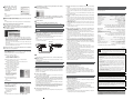
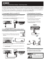
YWA-10/EN-1
Features
English
YWA-10
Wireless Network Adapter
Owner’s Manual
© 2012 Yamaha Corporation
Setup procedure
Allows Yamaha AV products equipped with a
NETWORK port and a DC OUT jack to be connected
with a wireless LAN.
Compatible devices can connect to the YWA-10
through a USB connector instead of a DC OUT jack.
Refer to the website below for a list of compatible
devices.
http://yamaha.com/
Printed in China
To assure the finest performance, please read this
manual carefully.
Keep it in a safe place for future reference.
Step 2-A
Checking the base unit
• Check that the Wireless LAN router (base unit)
can connect to the Internet.
Connecting to the base unit
AV Receiver
• When the Wireless LAN router (base unit) has a
WPS button
^ Carry out the procedures in “Step 2-A
Connecting to the base unit (using WPS)” to
connect to the base unit.
• When the Wireless LAN router (base unit) does
not have a WPS button
^ Carry out the procedures in “Step 2-B
Connecting to the base unit (manual
configuration)” to connect to the base unit.
✻ If connecting using “(using WPS)” does not
succeed, refer to “(manual configuration)” and
configure the connection.
Package contents
Check that the following accessories are supplied with
the product.
Wireless Network
Adapter (this unit)
YWA-10
LAN cable
Connecting to the base unit
(using WPS)
Step 2-B
Notes
• This explanation details the procedure for connecting using the WPS
function. When using a base unit that is not equipped with a WPS
function, refer to “Step 2-B Connecting to the base unit (manual
configuration)” at right.
• You will need to change the IP address of this unit if you are using more
than one YWA-10 at the same time.
Refer to “Troubleshooting” on the reverse page for more details.
1. Supply power to the YWA-10
a Turn on the power of the AV product that you wish to connect this unit
to.
b Use the supplied USB power cable to connect the power connector on
this unit to the DC OUT jack on the AV product.
The indicator on the front panel of this unit lights. Wait for approximately one
minute after the indicator lights and then carry out the following procedure.
Note
If the AV product is not equipped with a DC OUT jack, connect to the USB
connector on the front panel.
Rear Panel
Modem
Connecting to an AV product
AV Receiver
Connecting to the base unit
(manual configuration)
Notes
• When making a manual connection to the base unit, or when you are
unable to connect using the procedure described in “Step 2-A Connecting
to the base unit (using WPS)” at left, refer to the explanation below.
• If the PC you are using to configure this unit is connected to the wireless
LAN, turn the PC’s wireless LAN function off.
• You will need to change the IP address of this unit if you are using more
than one YWA-10 at the same time.
Refer to “Troubleshooting” on the reverse page for more details.
1. Check the network that you are attempting to
connect to.
You will need the setting information from the wireless LAN router (base unit)
when connecting or setting up this unit. Have the following table ready for use.
* Refer to the owner’s manual of the wireless LAN router (base unit) for
information on how to check its wireless LAN settings.
■ When using WEP security settings
(1)
(2)
(3)
(4)
(5)
Name
SSID
Security mode
Security key type
Default key
Password
Wireless LAN setting
❑ Open
❑ Shared
❑ Hexadecimal*1
❑ ASCII*2
❑ Key 1 ❑ Key 2 ❑ Key 3 ❑ Key 4
*1: 16-digit number (0–9, A–F), *2: ASCII (0–9, A–Z, a–z)
■ When using WPA/WPA2 security settings
Internet
connection
USB power cable
The Wi-Fi CERTIFIED Logo is a
certification mark of the Wi-Fi
Alliance.
The Wi-Fi Protected Setup Mark
is a mark of the Wi-Fi Alliance.
Wireless LAN router
(base unit)
The firmware of this unit may be updated at times for
improvement. Please refer to the following website for
information on firmware updates.
http://yamaha.com/
Owner’s Manual (this manual)
2. Connect the base unit
a Press the WPS button on the wireless LAN router (base unit).
Refer to the owner’s manual of the wireless LAN router (base unit) for
information on how to use the WPS button.
b Press and hold the WPS button on the rear of this unit for more than 5
seconds and release it.
The WPS indicator on the front panel lights.
Press and hold for more
than 5 seconds.
Part names
Step 1
Upper surface of product
Rear
d
e
f
Checking the base unit
a Check that the wireless LAN router (base unit) can connect to the
Internet without difficulty.
Internet
connection
c Wait until the WPS indicator turns off (this will take two minutes at
most).
(1)
(2)
(3)
(4)
Name
SSID
Security mode
Encryption type
Password
Wireless LAN setting
❑ WPA-PSK
❑ TKIP
❑ WPA2-PSK
❑ AES
Note
Use only alpha-numeric characters (0–9, A–Z, a–z) for an SSID or password.
Otherwise, Yamaha cannot guarantee normal operation.
Refer to the owner’s manual of the wireless LAN router (base unit) for
information on how to change the SSID or password.
2. Connect this unit to a PC
a Turn the PC power on.
b Use the supplied LAN cable to connect the LAN1 port (or the LAN2 port)
on this unit to the LAN port on the PC. Then, use the supplied USB
power cable to connect the power connector on this unit to the USB
connector on the PC.
The indicator on the front panel of this unit lights. Wait for approximately one
minute after the indicator lights and then carry out the following procedure.
Internet connectivity
Side
Note
If the WPS indicator blinks, carry out procedure 2 again, starting at number
a.
Modem
abc
g
a POWER indicator
b WPS indicator
c WIRELESS indicator
d Power connector
e LAN1 port, LAN2 port
f WPS button
g Reset button
Things to check before setup
• If you do not already have an Internet connection, please apply for one
before setting up this unit.
• Do not connect the USB power cable to a USB hub.
Wireless LAN
router
(base unit)
Computer
Notes
• If you do not currently have an Internet subscription, please obtain one.
• A wireless LAN router is required to set up a connection using this
procedure. Please obtain a wireless LAN router if you do not have one
available.
b Check whether the wireless LAN router (base unit) is WPS compatible.
Check the owner's manual and other documentation supplied with the
wireless LAN router.
Note
WPS (Wi-Fi Protected Setup) is a function that uses a button to configure
connections and security on wireless LAN devices.
*Some Wi-Fi devices have “WPS” written on them.
This completes connection with the base unit. Proceed to “Step 3
Connecting to an AV product”.
3. Setting up this unit
a Start the web browser on the PC.
b Enter “ywa.setup” in the
address field in the Web
browser, and press the Enter
key.
Note
If the login screen does not appear even after you enter “ywa.setup”, enter
“192.168.1.249” and press the Enter key. If the login screen still does not
appear, refer to “Troubleshooting”.
W When the wireless LAN router (base unit) has a WPS button
Carry out “Step 2-A Connecting to the base unit (using WPS)”, and then
“Step 3 Connecting to an AV product”, in that order.
W When the wireless LAN router (base unit) does not have a WPS
button
Carry out “Step 2-B Connecting to the base unit (manual configuration)”,
and then “Step 3 Connecting to an AV product”, in that order.
Continues to the back side.
c On the login screen, enter
“admin” in the user name field,
and
“password”
in
the
password field, and then click
the OK button.
Note
If you cannot login to the setup screen, check that you have entered the
correct letters.
d Where necessary, select the display language from the drop-down list.
The screen display language changes.
Note
The display examples in this manual use English as the display language.
h The “LAN Setup” screen appears. Change the IP address if it is already
being used by another device.
Check the settings and click [APPLY].
i The seconds before this unit restarts are counted down (30 seconds).
When the count reaches “0”, this unit will restart. Click “OK” and check
that this unit can connect to the access point.
j Close the browser.
k Remove the connected LAN cable and USB power cable.
e Click [Setup Wizard] and then [Next], in that order.
The “Wireless Site Survey” screen appears.
f On the “Wireless Site Survey” screen, choose the same SSID as in (1)
on the table in “1 Check the network that you are attempting to connect
to.” and then click [Next].
Notes
• When the SSID does not appear, click [Refresh] and then search again.
• If the SSID (the name of the device you are connecting to) does not
display even when the above operation is performed, the wireless LAN
router (base unit) power is turned off, or the SSID name notification is
turned off (SSID Broadcast refusal).
In such cases, enter the same SSID as the wireless LAN router (base
unit) directly.
• It is recommended that you connect to an SSID with an RSSI (Received
Signal Strength Indication) of 50 or above.
This completes connection with the base unit. Proceed to “Step 3
Connecting to an AV product”.
Step 3
Connecting to an AV product
a Use the supplied LAN cable to connect the LAN1 port (or the LAN2 port)
on this unit to the NETWORK port on the AV product. Then, use the
supplied USB power cable to connect the power connector on this unit
to the DC OUT jack on the AV product.
The indicator on the front panel of this unit lights. Wait for approximately one
minute and then carry out the following procedure.
Note
If the AV product is not equipped with a DC OUT jack, connect to the USB
connector on the front panel.
Rear Panel
AV Receiver
g Follow the procedure in “1 Check the network that you are attempting
to connect to.” to set up this unit.
When (2) in the table is “Open / Shared”
Refer to “■ When using WEP security settings” in the table on the reverse
page to set up this unit.
a Enter the profile name of your choice in “profile name”.
b When (2) in the table is “Open”
^ Select “Open” under “Encryption”.
When (2) in the table is “Shared”
^ Select “SHARED” under “Encryption”.
c When (5) in the table is set to use a 10 or 5 letter password
^ Select “64Bit” under “Key Length”.
When (5) in the table is set to use a 26 or 13 letter password
^ Select “128Bit” under “Key Length”.
d When (3) in the table is “Hexadecimal”
^ Select “Hex” under “Key Format”.
When (3) in the table is “ASCII”
^ Select “ASCII” under “Key Format”.
e Enter the same encryption key
as in (5) on the table in the
same Encryption key field as in
(4) in the table.
For example, when (4) in the
table is “Key 1”, enter the same
password as “Encryption Key
1” from (5) in the table.
f Select the same default key as
(4) from the table in “Default Tx
Key”.
b Turn on the power of the AV product that you wish to connect this unit
to.
c Check that the network functions of the connected AV products
function correctly.
Refer to the owner’s manual of the AV product for information on these
network functions.
This completes the setup procedure.
Troubleshooting
■ The power does not turn on
• Check that the USB power cable is firmly connected to this unit and the AV
product.
• Check that the AV Receiver Network Standby is set to ON. (If Network
Standby is OFF, power supply to the DC OUT jack will turn OFF when the AV
Receiver is set to Standby.)
■ Cannot connect using WPS
• Only some devices are WPS compatible. If you are unable to connect using
WPS, configure the settings manually.
Refer to “■ When using WPA/WPA2 security settings” in the table on the
reverse page to set up this unit.
a Enter the profile name of your
choice in “profile name”.
■ An error occurs when “ywa.setup” or “192.168.1.249” is input in the
address field of the web browser, or the login screen does not appear.
• Check the IP address settings (automatic or fixed setting) of the PC. If the
PC is set to fixed setting, change it to automatic.
• The IP address of this unit may have changed from its default setting. Refer
to “Resetting this unit” and reset this unit.
• If you are using any security software, turn it off temporarily. Refer to the
owner’s manual of the security software for information on how to turn it off.
• If the wireless channel of the base unit is set to “12” or “13”, change it to a
channel between “1” and “11”. (USA and Canada models only)
b Enter the same password as in
(4) from the table in the “Preshared Key” field.
■ Cannot log in from the login screen
• The ID and password may have been changed. Refer to “Resetting this unit”
and reset this unit.
g Click [APPLY].
When (2) in the table is “WPA-PSK”/“WPA2-PSK”
c Click [APPLY].
Note
To register multiple base units repeat procedures e through g.
■ Unable to find the base unit in “Wireless Site Survey” on the setup
screen
• If this unit is too far away from the base unit (wireless LAN router, etc.) or
there is an obstacle between them, try searching again in close proximity to
the base unit, in a location where there are no obstacles between the two
devices.
• The base unit may be set to refuse SSID Broadcast. Set the SSID, security
mode, and key by hand.
■ Unable to configure settings in “Wireless Site Survey” on the setup
screen
• Check the SSID. If the base unit SSID or password contain characters that
this unit cannot use, the password is greater than 30 characters long, or the
SSID is greater than 32 characters long, change them to settings that are
compatible with this unit.
• Check the base unit security mode, and set the same security mode on the
YWA-10 setup screen.
• The password you have entered may be incorrect. Check the password and
re-enter it.
• If multiple base units are registered, select the units to which you wish to
connect, and click [Connect].
■ Not connected to the Internet, or connected to the Internet, but
experiencing sound skipping.
• There may be a problem with your Internet environment. Without using this
unit, check whether your PC can connect to the Internet, as in Step 1.
• Refer to “Step 3 Connecting to an AV product” and check that the products
and cables are connected correctly.
• If this unit is too far away from the base unit (wireless LAN router, etc.) or
there is an obstacle between them, try searching again in close proximity to
the base unit, in a location where there are no obstacles between the two
devices.
• If there is a microwave oven in the immediate area, electromagnetic waves
from the microwave oven may be interfering with the wireless transmissions.
Move further away from the microwave oven and try connecting again.
• The base unit may be restricting connections by MAC Address. Add the MAC
address written on the underside of this unit to the list of permitted
connections on the base unit.
• Turn on the power to this unit again.
• Turn on the power to the base unit (wireless LAN router, etc) again.
• Check the IP address settings (automatic or fixed setting) of the network
device to which this product is to be connected. If the network device is set to
fixed setting, change it to automatic.
• Check that the DHCP server function on the base unit is set to ON.
• Try removing and reinserting the LAN cable connecting this unit and the AV
Receiver.
• Connection is not possible if multiple YWA-10 units are in use, or if another
device is using the IP address “192.168.xxx.249”. Refer to “Changing the IP
address” and change to a unique IP address.
• If you are unable to connect even after performing the above procedure,
reset this unit. Refer to “Resetting this unit” for information on resetting.
• Audio content that utilizes a significant amount of data may not transmit
correctly over a wireless connection in some cases. Use audio formats that
require a small amount of data.
Resetting this unit
Note
Resetting this unit will erase all of its settings. Be sure to note down the
necessary information before resetting.
a Check that this unit’s power is on.
b Press the Reset button for at least 10 seconds.
c Release the Reset button when all the indicators are blinking.
When this unit restarts after approximately 2 minutes, resetting is complete.
When resetting is complete, set up this unit again, starting from “Step 2-A
Connecting to the base unit (using WPS)” or “Step 2-B Connecting to the base
unit (manual configuration)”.
Changing the IP address
a Reset this unit.
Refer to “Resetting this unit”.
b Connect this unit to a PC.
Refer to “2 Connect this unit to a PC” in “Step 2-B Connecting to the base
unit (manual configuration)”.
c Open the setting screen of this unit.
Refer to “3 Setting up this unit” in “Step 2-B Connecting to the base unit
(manual configuration)”, and carry out procedures 1-3.
d Click “Network” in the menu in the upper area of the setting screen.
e On the “LAN Setup” screen, enter “192.168.1.xxx” as an IP address.
Set the “xxx” in “192.168.1.xxx” to a number that is between 2 and 248, and
one that is not used by other devices.
f Click [APPLY].
g Set up this unit again.
Carry out “Step 2-A Connecting to the base unit (using WPS),” or “Step 2-B
Connecting to the base unit (manual configuration)”.
Factory default settings
User name (Login ID): admin
IP address: 192.168.1.249
Password: password
Specifications
Wireless section
Wireless type .................................. IEEE802.11n, IEEE802.11g, IEEE802.11b
Frequency of operation .......................................... US: 1—11 ch, EU: 1—13 ch
Frequency band ................................................ 2.4 GHz (2,400—2,483.5 MHz)
Type of modulation ...................... IEEE802.11n: OFDM, IEEE802.11g: OFDM,
IEEE802.11b: DSSS
Antenna gain...............................................................................................2 dBi
Antenna...................................................................Internal antenna x 2 (2T2R)
Access mode .......................................................................Infrastracture mode
Bandwidth .......................................................................... 20 MHz and 40 MHz
Security ...................WPA2-PSK (TKIP), WPA2-PSK (AES), WPA-PSK (TKIP),
WPA-PSK (AES), SHARED, OPEN (WEP: 64bit/128bit,
Key format: ASCII/Hexadecimal), Disabled (No encryption)
Wired section
Ethernet type......................IEEE802.3u (100Base-Tx), IEEE802.3i (10Base-T)
Interface ....................................................................... RJ-45 port x 2 (LAN x 2)
Ethernet cable......................................................................Category 5 or more
Configuration window requirement
OS............................................... Windows 7(32bit/64bit)/Vista(32bit/64bit)/XP,
Mac OS X 10.4/10.5/10.6, CPU: Intel/PowerPC support)
Browser................................ Internet Explorer 6 or above, Firefox 5.0 or above
General
Dissipation power.......................................... Maximum of approximately 2.3 W
Power supply ................................................................................DC +5V 0.5 A
External dimensions.......................... 78 x 70 x 22 (mm) *Excluding protrusions
Weight..........................................................................................................62 g
Operating temperature range.........................................Temperature: 0—40 °C
Humidity: 10—90 % (No condensation)
Strage temperature range..........................................Temperature: –20—60 °C
Humidity: 10—90 % (No condensation)
* Specifications are subject to change without notice.
(E.U. only)
This symbol mark is according to the EU directive 2002/96/EC.This symbol
mark means that electrical and electronic equipment, at their end-of-life, should
be disposed of separately from your household waste. Please act according to
your local rules and do not dispose of your old products with your normal
household waste.
■ Precautions
Read this before using this unit.
To assure the finest performance, please read this manual carefully. Keep it in a safe place
for future reference.
1 Install this unit in a cool, dry, clean place away from direct sunlight, heat sources, and
sources of excessive vibration, dust, moisture, and/or cold. (Do not use/keep this unit in
a car etc.)
2 Locate this unit away from other electrical appliances, motors, or transformers to avoid
humming sounds.
3 Do not expose this unit to sudden temperature changes from cold to hot, and do not
locate this unit in an environment with high humidity (i.e. a room with a humidifier) to
prevent condensation inside this unit, which may cause an electrical shock, fire, damage
to this unit, and/or personal injury.
4 Do not clean this unit with chemical solvents; this might damage the finish. Use a clean,
dry cloth.
5 Do not attempt to modify or fix this unit. Contact qualified Yamaha service personnel
when any service is needed. The cabinet should never be opened for any reason.
6 Be sure to read the “Troubleshooting” section regarding common operating errors before
concluding that the unit is faulty.
7 Before moving this unit, disconnect USB power cable from the AV product.
Do not use this unit within 22 cm (9 inches) of persons with a heart pacemaker implant or
defibrillator implant.
Explanations regarding GPL
This product utilizes GPL/LGPL open-source software in some sections. You have the right
to obtain, duplicate, modify, and redistribute this open-source code only. For information on
GPL/LGPL open source software, how to obtain it, and the GPL/LGPL license, refer to the
Yamaha Corporation website (http://download.yamaha.com/sourcecodes/ywa-10/).
• This product is limited to indoor use only.
• Frequencies used by this product may be prohibited to use in some counties. As a user of
this product, you have responsibilities to use this product only in the intended countries
and confirm that this product is set to use frequencies and channels that are allowed to
use in your country. Violators may be punishable by law of the country. For information
about laws of each country, please refer to “ERC/REC 70-03”.
We, the manufacturer (Yamaha Corporation) hereby declare that this equipment (Wireless
Network Adapter), model YWA-10 is in compliance with the essential requirements and
other relevant provisions of Directive 1999/5/EC.
• Microsoft, Windows 7, Windows Vista and Windows XP are registered trademarks or
trademarks of Microsoft Corporation in the U.S. and other countries.
• Other product names, technology names, and company names mentioned in this manual may
be trademarks or registered trademarks of their respective owners and are hereby
acknowledged.
YWA-10
Wireless Network Adapter - Quick Setup Guide
The YWA-10 Wireless Network Adapter can be used to connect the RX-V773 to a wireless home network.
This Quick Setup Guide walks you through using Wi-Fi Protected Setup (WPS) to automatically configure
the YWA-10 to your home network. If your wireless router does not support WPS or you need additional
KHOSSOHDVHUHIHUWRWKH<:$2ZQHU·V0DQXDORUYLVLWKWWSZUGLW<:$+(/3
1. Connecting the YWA-10 to the RX-V773
3. Checking Network Connectivity
a. Connect the supplied USB power cable to the YWA-10 and the RX-V773
back panel DC OUT 5V-0.5A USB power port.
Once the YWA-10 is connected to the RX-V773, you
can test internet connectivity by going to the Net Radio
input and selecting a station.
b. Power ON the RX-V773 and wait for one minute after the green power
light on the YWA-10 is lit, then proceed to step 2.
Rear Panel
a. Press the Net button on the receiver remote
repeatedly until Net Radio is displayed.
b. If the On-Screen Display shows Bookmarks,
Locations, Genres, etc. you are successfully
connected to the internet.
AV Receiver
RX-V773
AV Receiver
RX-V773
2. Connecting the YWA-10 to your wireless network
a. Press the WPS button on your wireless router.
Press WPS
button
YWA-10
b. Press and hold down the WPS button on the rear of the
YWA-10 for 10 seconds or until the WPS indicator light
turns solid.
Wireless router
Press and hold for 10 seconds or
until the WPS light turns solid.
Modem
c. Remove your finger from the WPS button and wait for the WPS light to go
out. This can take up to 2 minutes.
Internet
connection
Wireless router
1RWH,IWKH:36LQGLFDWRUEOLQNVGLVFRQQHFWSRZHURIWKH<:$DQG
start over at Step 1.
Notes:
d. Connect the supplied Network cable from the YWA-10 to the Network port
on the RX-V773.
Rear Panel
If your wireless router does not support WPS or if you
need additional help, please refer to the YWA-10
2ZQHU·V0DQXDORUYLVLWKWWSZUGLW<:$+(/3
The Wi-Fi CERTIFIED Logo is a
certification mark of the Wi-Fi
Alliance.
The Wi-Fi Protected Setup Mark
is a mark of the Wi-Fi Alliance.
AV Receiver
RX-V773
YWA10BL QSG
0-27108-10770-7
YWA-10
Using the YWA-10 wireless network adapter with one of the AV receivers listed below
English
When updating the receiver firmware, please follow these instructions.
- Perform the firmware update using a USB memory device. Firmware and instructions can be downloaded from Yamaha's website.
http://download.yamaha.com/
- If updating the firmware over the network using YWA-10, connect the supplied USB power cable to the USB port on the receiver's
front panel.
The DC OUT terminal on the rear panel is not designed for firmware updates. It may not be possible to update the firmware
depending on wireless network conditions.
AV Receiver model list:
- RX-A3020, RX-A2020, RX-A1020, RX-A820, RX-A720
- RX-V3073, RX-V2073, RX-V1073, RX-V773, RX-V673
- HTR-7065, HTR-6065
Utilisation de l’adaptateur réseau sans fil YWA-10 à l’aide de l’un des ampli-tuners audio-vidéo ci-dessous
© 2012 Yamaha Corporation
Français
[Q]
8YAMAHA
1
YWA-10
:t®®l
FCC INFORMATION (for US customers)
1 IMPORTANT NOTICE: DO NOT MODIFY TillS UNIT!
lbis product, when installed as indicated in the instructions contained in this
manual, meets FCC requirements. Modifications not expressly approved by
Yarnaha may void your authority, granted by the FCC, to use the product.
IMPORTANT: When connecting this product to accessories and/or another
product use only high quality shielded cables. Cable/s supplied with this
product MUST be used. Follow all installation instructions. Failure to follow
instructions could void your FCC authorization to use this product in the
USA.
NOTE: This product has been tested and found to comply with the requirements
listed in FCC Regulations, Part 15 for Class "B" digital devices. Compliance
with these requirements provides a reasonable level of assurance that your
use of this product in a residential environment will not result in harmful
interference with other electronic devices. This equipment generates/uses
radio frequencies and, if not installed and used according to the instructions
found in the users manual, may cause interference harmful to the operation
of other electronic devices.
Compliance with FCC regulations does not guarantee that interference will
not occur in all installations. If this product is found to be the source of
interference, which can be detennined by turning the unit "OFF' and "ON",
plea~e try to eliminate the problem by using one of the following measures:
Relocate either this product or the device that is being affected by the
interference.
Utilize power outlets that are on different branch (circuit breaker or fuse)
circuits or install AC line filter/s.
In the case of radio or TV interference, relocate/reorient the antenna. If the
antenna lead-in is 300 ohm ribbon lead, change the lead-in to coaxial type
cable.
If these corrective measures do not produce satisfactory results, please
contact the local retailer authorized to distribute this type of product. If you
can not locate the appropriate retailer, please contact Yamaha Corporation
of America A/V Division 6600 Orangethorpe Ave., Buena Park, CA 90620.
The above statements apply ONLY to those products distributed by Yarnaha
Corporation of America or its subsidiaries.
COMPLIANCE INFORMATION STATEMENT (DECLARATION OF CONFORMITY PROCEDURE)
Responsible Party
Address
Telephone
Type of Equipment
Model Name
Yamaha Corporation of America AIV Division
6600 Orangethorpe Avenue, Buena Park,
CA 90620, USA
1-714-522-9011
Wireless Network Adapter
YWA-10
Yamaha Canada Music Ltd.
135 Milner Avenue, Toronto, Ontario,
MIS 3R1, Canada
1-416-298-1311
• This device complies with Part 15 of the FCC Rules and RSSGen of IC Rules.
• Operation is subject to the following two conditions: I) this device may not cause harmful interference, and 2) this device must accept any
interference received including interference that may cause undesired operation.
See the "Troubleshooting" section at the end of this manual if interference to radio reception is suspected.
FCC WARNING
Change or modifications not expressly approved by the party responsible for compliance could void the user's authority to operate the equipment.
NOTICE
This equipment has been tested and found to comply with the limits for a Class B digital device, pursuant to part 15 of the FCC Rules. These limits are
designed to provide reasonable protection against harmful interference in aresidential installation.
This equipment generates, uses and can radiate radio frequency energy and, if not installed and used in accordance with the instructions, may cause
harmful interference to radio communications. However, there is no guarantee that interference will not occur in a particular installation. If this
equipment does cause harmful interference to radio or television reception, which can be determined by turning the equipment off and on, the user is
encouraged to try to correct the interference by one or more of the following measures:
- Reorient or relocate the receiving antenna.
- Increase the separation between the equipment and receiver.
- Connect the equipment into an outlet on a circuit different from that to which the receiver is connected.
- Consult the dealer or an experienced radioffV technician for help.
This equipment compiles with FCCIIC radiation exposure limits set forth for uncontrolled equipment and meets the FCC radio frequency (RF)
Exposure Guidelines in Supplement C to OET65 and RSS-1 02 of the IC radio frequency (RF) Exposure rules. This equipment has very low levels of
RF energy that it deemed to comply without maximum permissive exposure evaluation (MPE). But it is desirable that it should be installed and
operated with at least 20 em and more between the radiator and person's body (excluding extremities: hands, wrists, feet and ankles).
This transmitter must not be co-located or operated in conjunction with any other antenna or transmitter.
Warranty policy for U.S. and
Cana~a
customer
Your Yamaha product is covered by a limited warranty for one year from the date of purchase. In the unlikely event of failure due to defective materials
or workmanship, Yamaha will repair or replace them at no charge. Please visit our website for full details.
U.S.: (http://www.yamaha.com/yec/), Canada: (http://www.yamaha.ca/)
YAMAHA CORPORATION
© 201 2 Yama ha Corporation
Printed in China
II
INFORMATION DE LA FCC (pour les clients residant aux Etats-Unis)
1
AVIS IMPORTANT : NE PAS APPORTER DE MODIFICATIONS A
CET APPAREIL !
Cet appareil est conforme aux exigences de Ia FCC s'il est installe selon
les instructions du mode d'emploi. Toute modification non approuvee
expressement par Yamaha peut invalider l'autorisation de Ia FCC
d'utiliser cet appareil.
IMPORTANT: N'utiliser que des cables blindes de haute qualite pour le
raccordement de cet appareil a des accessoires et/ou a un autre appareil.
Seuls le ou les cables foumis avec le produit DOIVENT etre utilises.
Suivre les instructions concernant !'installation. Lenon respect des
instructions peut invalider l'autorisation, accordee par Ia FCC, d'utiliser
ce produit aux Etats-Unis.
REMARQUE : Cet appareil a ete teste et declare conforme aux normes
relatives aux appareils numeriques deClasse<< B >>, telles que fixees dans
I' Article 15 de Ia Reglementation FCC. Ces normes sont destinees a
assurer une protection suffisante contre les interferences nuisibles avec
d' autres appareils electroniques dans une installation residentielle. Cet
equipement genere et utilise des frequences radio qui, en cas
d'installation et d'utilisation non conformes aux instructions du mode
d'emploi, peuvent etre a l'origine d' interferences empechant d'autres
appareils de fonctionner.
Cependant, Ia conformite a Ia Reglementation FCC ne garantit pas I' absence
d'interterences dans une installation particuliere. Si cet appareil devait
produire des interterences, ce qui peut etre determine en
<< ETEIGNANT >>,puis en<< RALLUMANT » l'appareil, l'utilisateurest
invite aessayer de corriger le probleme d'une des manieres suivantes :
Reorienter cet appareil ou le dispositif affecte par les interterences.
Utiliser des prises d'alimentation branchees sur differents circuits (avec
interrupteur de circuit ou fusible) ou installer un ou des filtres pour ligne
secteur.
Dans le cas d'interterences radio ou TV, changer de place l' antenne et Ia
reorienter. Si I' antenne est un conducteur plat de 300 ohms, rem placer ce
cable par un cable de type coaxial.
Si ces mesures ne donnent pas les resultats escomptes, priere de contacter le
detaillant local autorise acommercialiser ce type d'appareil. Si ce n'est pas
possible, priere de contacter Yamaha Corporation of America AIV Division,
6600 Orangethorpe Ave., Buena Park, CA 90620.
Les declarations precedentes concement EXCLUSIVEMENT les appareils
commercialises par Yamaha Corporation of America ou ses filiales.
DECLARATION SURLES INFORMATIONS DE CONFORMITE
(PROCEDURE DE DECLARATION DE CONFORMITE)
Partie responsable
Addresse
Telephone
Type d'equipement
Nom de modele
Yamaha Corporation of America AN Division
6600 Orangethorpe A venue
Buena Park, CA 90620, USA
1-71 4-522-9011
Adapteur de reseau sans-fi1
YWA-10
Yamaha Canada Music Ltd.
135 Milner Avenue, Toronto, Ontario,
MIS 3R1, Canada
1-416-298-1311
• Cet appareil est conforme a Ia Partie 15 du Reglement FCC et au RSS-Gen du Reglement IC.
• Le fonctionnement est soumis aux deux conditions suivantes: I) Cet appareil ne peut pas causer d'interferences nuisibles et 2) Cet appareil doit
recevoir toutes les interferences, y compris celles pouvant entralner des problemes de fonctionnement.
Consultez le mode d'emploi si vous soupc;onnez que Ia reception radio subit des interferences.
AVERTISSEMENT FCC
Tout changement apporte sans !'approbation expresse du fabricant pourrait entrainer l'annulation du droit d'utilisation de l' appareil.
REMARQUE
Cet appareil a ete teste et il s' est avere etre conforme aux limites determinees pour un appareil numerique deClasse B, conformement a Ia partie 15 du
Reglement FCC. Ces limites sont destinees a offrir une protection raisonnable contre les interferences nuisibles pouvant survenir en cas d'utilisation de
ce produit dans un environnement domestique.
Cet appareil produit, utilise et peut emettre de l'energie radioelectrique et, s'il n'est pas installe conformement aux instructions, peut provoquer des
interferences radio. II n'est toutefois pas garanti qu'aucune interference ne se produira dans le cas d'une installation donnee. Si l'appareil provoque des
interferences nuisibles a Ia reception de programmes radio ou de television, ce qui peut etre determine en eteignant, puis en allumant I' appareil,
l'utilisateur est prie de tenter de corriger le probleme en prenant l'une ou plusieurs des mesures suivantes:
- Reorienter ou deplacer l'antenne receptrice.
- Eloigner davantage r appareil du recepteur.
- Raccorder l'appareil une prise d ' un circuit different de celui du recepteur.
-Consulter le revendeur ou un technicien radio/tele experimente.
a
Cet appareil est conforme aux limites FCC!IC d'exposition aux rayonnements detinies pour les appareils non commandes et satisfait aux directives
d ' exposition aux frequences radio (RF) FCC de I' Annexe C des reglements OET65 et RSS-102 d'exposition aux frequences radio (RF) IC. Cet appareil
possede des niveaux d ' energie RF tres bas, consideres conformes aux taux d'exposition maximum autorises (MPE) non controles. Mais il est toutefois
preferable d ' installer et d'utiliser 1' appareil en conservant une distance minimum de 20 em entre 1' emetteur et toute personne (sauf les extremites:
mains, poignets, pieds et chevilles).
Ce emetteur ne peut pas etre place a proximite de ou utilise conjointement avec tout autre emetteur ou antenne.
Garantie Canadienne
Votre produit Yamaha est couvert par une garantie limitee de un an a compter de la date d'achat. Dans le cas improbable d'un echec du aux materiaux
ou !'execution defectueux, Yamaha les reparera ou les remplacera gratuit.
Veuillez visiter notre site Web pour les details complets (http://www.yamaha.ca/)
a
5300-00004879-01W