1
INSTALLATION MANUAL
6178-2203
Galvanic
Isolation
Transient
Protection
CE
Approved
Tele modem
V.32bis
www.westermo.se
© Westermo Teleindustri AB • 2000 • REV. A
85
4
/
2
3
TD
TD-32
Table of Contents
Introduction
Safety
.....................................................................................................................................................................
4
..........................................................................................................................................................................................
4
..................................................................................................................................................................
5
..........................................................................................................................................................................
6
Specifications
Installation
RS-232/V.24 Connections
Line Connection
...........................................................................................................................
7
........................................................................................................................................................
7
Typical TD-32 Line Connections
.....................................................................................................
TD-32/485 (RS-422/485 interface)
DIP Switch Setup
................................................................................................
....................................................................................................................................
8
9
10–13
LED Status Indicators
...................................................................................................................................
13
DTE Command Lines
....................................................................................................................................
14
AT Command Set .................................................................................................................................... 15–34
Result Codes
S-Registers
..............................................................................................................................................................
.........................................................................................................................................................
Application Examples
Glossary
6178-2203
35
36–45
......................................................................................................................
46–49
................................................................................................................................................................
50–53
3
Introduction
The Westermo TD-32 is an industrialised dial and leased line modem. This modem has been developed to be used in industrial applications and has some features you would not expect to find on a
normal modem.
Terminal data rates of up to 57.6 kbit/sec can be handled using data compression and error correction. The maximum line modulation speed is 14,400 bit/sec (V.32bis).
Leased line connections can be made on 2 or 4 wires. The modem can also be used on ordinary twisted pair cables to provide long distance asynchronous communications.
A watchdog facility continually monitors the power supply and internal hardware as well as the operational software. In the event of a problem the modem automatically resets. This feature has been
included to make the unit more suitable for use in unmanned locations.
The TD-32 is available in two standard versions for power supply by 230V AC or 12–36VDC.
Special 115V AC and 36–60V DC models are also available on request.
Westermo have implemented commands often left out of standard modems. Two examples of these
Westermo specific AT-commands are &D and &A (see AT-command description for further information).
The TD-32 can handle 11 data bits and has a special 2 stop bit mode to allow the unit to be used in
applications many modems can’t handle.
The TD-32 has been designed with the engineer in mind, hence the extensive information on the
command set, S registers, DIP switched and error codes. We have endeavoured to include all
necessary information however if you need more please do not hesitate to call us.
Safety
This equipment should only be installed by professional service personnel. If the unit is intended
for permanent connection to mains supply, there should be a readily accessible disconnect device
(circuit breaker) incorporated into the fixed wiring.
Line connections on this equipment are designed for connection to TNV circuits.
The mains connection is classified as excessive voltage.
Description of the above classifications are given in EN60950:1992.
The TD-32DC shall only be installed to a power supply of the type SELV.
4
6178-2203
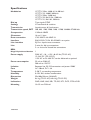
Specifications
Modulation
Dial up
Settings
Transmission
Transmission speed, DET
Compression
Characters
Error correction
Interface
Line interface
Line
CCITT V.32bis, 4 800 till 14 400 bit/s
CCITT V.32, 4 800/9 600 bit/s
CCITT V.22bis, 2 400 bit/s
CCITT V.22, Bell 212A, 1200 bit/s
CCITT V.21, Bell 103, 300 bit/s
Tone signals DTMF
AT-commands & switches
Asynchronous & Synchronous
300, 600, 1 200, 2 400, 9 600, 19 200, 38 400 & 57 600 bit/s
V.42bis & MNP5
Up to 11 bitar
V.42, MNP 2-4 & MNP 10
EIA RS-232-C/V.24. RS-422/485 is an option
RJ12 or 4-pole screw connector
2-wire for dial up connections
2- or 4-wire for leased line connections
REN,
Ringer Equivalence Number
1
Power supply
230V AC –10 – +15%, 48–62 Hz (TD-32 AC)
12–36V DC (TD-32 DC)
115V AC or 36–60V DC can be delivered as optional
25 mA at 230V AC
200 mA at 12V DC
Between line, RS-232 connection and power 1500V
AC 100mA, DC 1.6A
5–50°C surrounding temperature
0–95% RH, without condensation
55x100x128 mm (WxHxD)
0.6 kg (TD-32 AC) & 0.4 kg (TD-32 DC)
PWR, LINE, ANS, REL, TD, RD, RTS, DCD, DTR & DSR
On 35 mm DIN-rail
Power consumption
Isolation
Fuse
Temperature
Humidity
Dimensions
Weight
Indications
Mounting
6178-2203
5
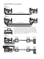
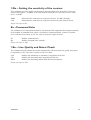
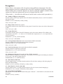
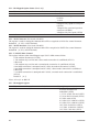
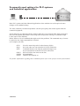
Installation
5
4
3
2
25-pole D-sub
for RS-232/V.24
connection
PWR
Connection
1
▼
6
▼
▼
Line connection
screw block
7
▼
6
Line
connection
RJ-12
8
Screw-block for
RS-232/V.24
connection
▼
Computers or other equipment
are connected through an
RS-232/V.24 connection.
This connection can be made
either to the 25-pole D-sub or
the 9-pole screw connector.
Do not use ribbon cable for
RS-232 connections.
9
Light
emitting
diodes
▼
The modem should be connected in the following way:
Power connection is made
through screw-block at bottom
right corner.
For 115V AC or 230V AC it is a
3-pole connector, and for 12–36
or 36–60V DC a 2-pole connector.
6178-2203
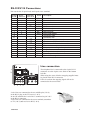
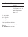
RS-232/V.24 Connections
Pin outs for the 25-pole D-sub and 9-pole screw terminal:
Direction
DCE-DTE
---
←
←
←
←
←
---
←
←
←
←
←
←
←
←
←
←
←
←
25-pos. Screw
D-sub
Terminal
1
2
8
3
7
4
6
5
5
6
2
7
1
8
4
9
10
12
15
17
20
3
21
22
9
23
24
25
Name
Description
PE
TXD
RXD
RTS
CTS
DSR
SG
DCD
Protective earth
Transmit data
Receive data
Request to send
Clear to send
Modem ready
Signal ground
Data carrier detect
Continuous high
Continuous low
Speed indication (1200/2400)
Synchronous TXD clock from modem
Synchronous RXD clock from modem
Data terminal ready
Request of remote digital loop back
Ring indicator
Data speed select (1200/2400)
External synchronous clock
Test indication signal
DRS
TXC
RXC
DTR
RDL
RI
DRS
EXC
TI
The other pins in the 25-pole D-sub should be left unconnected.
Line connection
1
:
6
The telephone line is connected to the 6-pole RJ-12
connector or to the 4-pole screw block in the bottom
left side.
When using the screw-block a strap plug supplied must
be placed in the RJ-12 connector.
If this is not done the outgoing signal will not be
connected to the screw-block.
1
2
3
4
2-wire lines are connected to the two middle pins (3 & 4)
in the RJ-12 plug or the TX screws (1 & 2).
In the UK modems the 2-wire line is connected to pin 2 & 5
in the RJ-12 connector.
4-wire lines are connected to the screw terminal, transmitter
to TX (1 & 2) and receiver to RX (3 & 4).
6178-2203
12345678
7
Typical TD-32 line connections
4-position
screw terminal
Leased line 2-wire
4-position
screw terminal
Leased line 4-wire
Handshaking
9
8
7
6
5
4
3
2
1
The TD-32 is delivered with a factory setting for “hardware handshake” with RTS-CTS which means that if only TX, RX and GND
are connected no data will be sent on the receiving modem’s RS-232
connection unless RTS is high. The problem can be solved by placing
a jumper between RTS (screw terminal no 6) and for example DSR
(screw terminal no 2) or by disabling the handshake with the command
AT&K0, or with switch 3:2 (switch settings).
4-position
screw terminal
Telephone
Exchange
Telephone
Exchange
Telephone
modem
Telephone
Exchange
Telephone
modem
Dial up line 2-wire
RJ-12 kontakt
3
4
Telephone
Exchange
Dial up line 2-wire
8
6178-2203
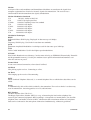
TD-32/485
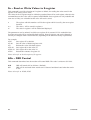
TD-32/485 (RS-422/485 interface)
As an option the TD-32 can be supplied with an RS-422/485
interface. This product is referred to as the TD-32/485.
On the TD-32/485 the RS-232/V.24 connection on the screw
terminal on upper front side of the unit has been replaced with
an RS-422/485 interface. All other features remain identical
between the standard TD-32 and TD-32/485. The TD-32/485
can still be connected to an RS-232/V.24 port using the 25-pole
D-sub. Please note that there is no galvanic isolation between
the RS-232 and the RS-422/485 ports so they should not be
connected simultaneously.
The RS-422/485 connections are made as shown below.
Please note that the selection of 2 or 4 wire and termination or
no termination is done by linking between some of the screw
terminals.
9
8
7
6
5
4
3
2
1
S1 2/4 T2 T4 GND T- T+ R- R+
WIRE
RS 422/485
V24/RS232-C
PWR
TD
RD
RTS
DCD
LINE
ANS
REL
Connection
RS-422
Termination
4-wire
4-wire
9
8
7
6
5
4
3
2
1
S1 2/4 T2 T4 GND T- T+ R- R+
WIRE
RS 422/485
9
8
7
TD
RD
RTS
RTS
DCD
DCD
LINE
LINE
ANS
ANS
Connection
RS-485
5
4
3
2
1
RS 422/485
9
8
7
6
5
4
3
2
1
S1 2/4 T2 T4 GND T- T+ R- R+
WIRE
RS 422/485
V24/RS232-C
V24/RS232-C
PWR
TD
TD
RD
RD
RTS
RTS
DCD
DCD
LINE
LINE
ANS
ANS
6178-2203
1
Termination
2-wire
S1 2/4 T2 T4 GND T- T+ R- R+
WIRE
PWR
2
RS 422/485
TD
6
3
V24/RS232-C
RD
7
4
PWR
PWR
8
5
S1 2/4 T2 T4 GND T- T+ R- R+
WIRE
V24/RS232-C
9
6
9
DIP Switch Setup for Dial-up and Leased Line
Disconnect power before changing DIP-switches.
Use ESD-protection when changing switches.
The DIP-switches can be used to provide the following settings.
The DIP-Switches are underneath the top lid of the modem.
Non defined switches will be in off position.
Switch 1
9
8
7
6
5
4
3
2
1
Related
AT-commands
ON
Standard dial-up line
1 2 3 4
ON
Leased line, Answering
(ATE0Q1&C1&A1)
Leased line, Originating
(ATE0Q1&C1&A1)
1 2 3 4
ON
1 2 3 4
ON
1 2 3 4
ON
1 2 3 4
10
Do not abort if unwanted characters
are received when connecting
Escape sequence disabled
(All commands ignored in on-line mode)
(AT&A1)
(ATE0Q1&C1)
6178-2203
Switch 2
ON
Related
AT-commands
2–8 are not used
1 2 3 4 5 6 7 8
ON
For use of SW2:2 to 7
1 2 3 4 5 6 7 8
ON
Asynchronous communication
1 2 3 4 5 6 7 8
ON
1 2 3 4 5 6 7 8
ON
1 2 3 4 5 6 7 8
ON
1 2 3 4 5 6 7 8
Synchronous, external clock.
Clock from D-sub pin 24
Synchronous, internal clock,
The modem creates the clock
Synchronous slave.
Clock from line
ON
DTR/DSR disconnected
(AT&S0&D0&C0)
1 2 3 4 5 6 7 8
Switch 3
ON
Related
AT-commands
4-wire line connection
1 2 3 4 5 6 7 8
ON
2-wire line connection
1 2 3 4 5 6 7 8
ON
Flow control OFF
(AT&K0)
REL-mode disconnected
(AT\N0)
Speaker always OFF
(ATM0)
1 2 3 4 5 6 7 8
ON
1 2 3 4 5 6 7 8
ON
1 2 3 4 5 6 7 8
ON
PLC settings
(ATQ1E0&C1&K0&A1)
1 2 3 4 5 6 7 8
ON
1 2 3 4 5 6 7 8
ON
1 2 3 4 5 6 7 8
6178-2203
DCD follows the state
of the line carrier
Line monitor disabled and
no re-training
(AT&C1)
%E0
11
Switch 4 (Serial speed and format)
ON
1 2 3 4 5 6 7 8
Automatic detection of serial
speed and format
Related
AT-commands
ON
300 bit/s
1 2 3 4 5 6 7 8
ON
600 bit/s
1 2 3 4 5 6 7 8
ON
1 200 bit/s
1 2 3 4 5 6 7 8
ON
2 400 bit/s
1 2 3 4 5 6 7 8
ON
4 800 bit/s
1 2 3 4 5 6 7 8
ON
9 600 bit/s
1 2 3 4 5 6 7 8
ON
19 200 bit/s
1 2 3 4 5 6 7 8
ON
38 400 bit/s
1 2 3 4 5 6 7 8
ON
57 600 bit/s
1 2 3 4 5 6 7 8
ON
7 bits no parity, [7N]
1 2 3 4 5 6 7 8
ON
7 bits even parity, [7E]
1 2 3 4 5 6 7 8
ON
7 bits odd parity, [7O]
1 2 3 4 5 6 7 8
ON
8 bits no parity, [8N]
1 2 3 4 5 6 7 8
ON
8 bits even parity, [8E]
1 2 3 4 5 6 7 8
ON
8 bits odd parity, [8O]
1 2 3 4 5 6 7 8
ON
1 2 3 4 5 6 7 8
ON
1 2 3 4 5 6 7 8
Direct mode. [8E] or [8O]
[8O] in command mode
(AT\N1)
Direct mode. [7E] or [7O]
[8N] in command mode
(AT\N1)
ON
2 stop bits
1 2 3 4 5 6 7 8
12
6178-2203
Switch 5 (line modulation)
Related
AT-commands
ON
Used saved parameters
1 2 3 4 5 6 7 8
ON
V.21; 300 bit/s
(ATF1)
V.22; 1 200 bit/s
(ATF4)
V.22bis; 2 400 bit/s
(ATF5)
V.32bis; 4 800 bit/s
(ATF6)
V.32bis; 7 200 bit/s
(ATF7)
V.32bis; 9 600 bit/s
(ATF8)
V.32bis; 12 000 bit/s
(ATF9)
V.32bis; 14 400 bit/s
(ATF10)
Auto detect mode
(ATF0)
1 2 3 4 5 6 7 8
ON
1 2 3 4 5 6 7 8
ON
1 2 3 4 5 6 7 8
ON
1 2 3 4 5 6 7 8
ON
1 2 3 4 5 6 7 8
ON
1 2 3 4 5 6 7 8
ON
1 2 3 4 5 6 7 8
ON
1 2 3 4 5 6 7 8
ON
1 2 3 4 5 6 7 8
LED Status Indicators
PWR
LINE
ANS
REL
TD
RD
RTS
DCD
DSR
Full Intensity
The modem is functioning normally
Half intensity
The modem is in test mode
Occasional flashing with speaker click Power supply problem
1:6, on:off ratio
RAM error
On/off with speaker click
Modem unable to start
LED lights up when the modem has the line
LED flashes when a ring is detected on the line. The ANS indicator shines
constantly when answering an incoming call and remains lit thereafter
to indicate the modem is in auto answer mode.
LED flashes when the modem is in both error correcting and compressing mode.
When the modem is only in error correcting mode this LED is on.
When the modem is in direct or normal mode this LED remains off.
Transmitted Data: Displays data received from the local RS-232/V.24 port
Received Data: Displays data leaving the modem on the RS-232/V.24 port
Request to Send signal from the DTE
Data Carrier Detect modem signal
Data Set Ready modem signal
Please also refer to AT&C, AT\N, AT&T, ATS0
6178-2203
13
DTE Command Lines
In order to send commands to the modem, a prefix must be entered before the actual command(s).
This prefix is the ASCII string ‘AT’, which is an abbreviation for attention.
Commands may be entered in either upper or lowercase characters. The only exception is the prefix
‘AT’; both characters in this string must be of the same case.
Several commands may be entered on the same command line with or without space in between.
The command lines shall always be terminated by a carriage return (with the exception of the
‘A/’command).
The command consists of a single letter or a letter with the characters %, &, \, ( or * in front.
At Swedish terminals which lack \ in the character set Ö is used instead. After each command there
might be a parameter, most often a numerical value. Most parameter values are written to a memory
in the modem, an S-register. Different registers are effected depending on which command has been
used.
Commands and appurtenant parameters are sent to the modem through the serial port on the modem.
This must be connected to a terminal, a computer with a communication software or other equipment
which is able to send asynchronous, serial information. Each time ”AT” is sent to the modem it will
analyse which speed and parity is being used and will then switch to the serial port. In this modem it
is also possible to use DIP-Switches to set the most common parameters and also set the modem so
that it will not react on commands coming through the serial port.
In the description of commands it is written ”Default” within brackets after some commands, this
means that the command has this value when reset to the factory parameters (AT&F).
When communication is established with another modem it is still possible to reach the command
mode by sending an ”escape” sequence to the modem. This sequence consists of an interruption in
communication, after which three characters is sent, most often plus (+++) and after which it is silent
again. The silent periods are there to prevent that a text, containing this sequence, when sent will
interrupt the connection. The silence is usually 1 second, but can be changed in register S12.
Also the character can be changed, in register S2.
14
6178-2203
Description of commands
The modem can be configured and controlled with the AT-commands listed below.
A/ – Re-execute command
This command differs from the others since it will not be preceded by ”AT” and also not terminated by
ENTER.
A – Answer
The modem will wait for a carrier for the time that was specified in S7.
Please also refer to ATDn, S0, S1, S7, S8, S9, S30
\An – Select Maximum MNP Block Size
This command controls the size of data blocks used during connections with MNP, error corrected
links. The value is written to S40 bit 6 and 7.
\A0
\A1
\A2
\A3
64 characters.
128 characters.
192 characters. (Default)
256 characters.
Please also refer to AT\N
&An – Interrupt connection negotiation
Usually the modem will abort the connection negotiation if characters are sent to the serial port during negotiation phase.
This command gives a possibility to ignore incoming characters.
&A0
&A1
Abort connection negotiation when characters are sent to the serial port. (Default)
The modem will ignore characters on the serial port during negotiation phase.
Please also refer to AT&D
Bn – Selecting CCITT or BELL
For historical reasons the American standard for 300 and 1200 baud is different than the international.
B0
B1
CCITT-mode (European standard) (Default)
BELL-mode (American phone company)
Please also refer to ATFn, S27
6178-2203
15
&Bn – DTR Dial Option
This command enables the modem to dial a number stored with &Zn=number when the DTR signal
goes from inactive to active signal level.
No automatic call with DTR. (Default)
Call on DTR.
&B0
&B1
Please also refer to AT&Z, AT&D
\Bn – Transmit Break to Remote
The command controls the length of the break-signal, in a non-error correction mode. The length is
depending of the value n and is in multiples of 100 mS. During an error corrected link break will only
be transmitted to the remote modem through the active error correction protocol, giving no indication
of the length. The command works together with AT\K.
\Bn Break length in 100 mS units. The value can be between 1 and 9. (Default 3)
*B – Display blacklisted phone numbers
This command requests the modem to return a list with blacklisted phone numbers to the terminal
equipment when asked. The format of the response is shown by the example below.
Permanently forbidden phone numbers as defined by country requirements will not appear on this list.
If no blacklisted numbers exist, the modem responds with the result code OK.
Example:
NO. – PHONE NUMBER 1;
2;
3;
4;
5;
4175537660
8288924961
3887278862
3124839442
6284664
OK
Cn – Carrier control
This command is included for compatibility only, and has no effect other than returning a result code.
&Cn – DCD Option
The modem will handle the DCD signal depending on n. The parameter value is written to S21 bit 5.
On leased lines DCD always follows the state of the carrier.
&C0
&C1
16
DCD remains ON at all times. (Default.)
DCD follows the state of the carrier.
6178-2203
%C – Enable/disable data compression
Enables or disables data compression negotiation. The modem can only perform data compression on
an error corrected link. The parameter value is written to S41 bit 0 and 1.
%C0
%C1
%C2
%C3
Disables data compression. Resets S41 bit 1 to 0.
Enables MNP 5 data connection. Resets S41 bit 1.
Enables V.42bis compression. Sets S41 bit 1.
Enables both MNP 5 and V.42 compression.
Sets S41 bit 1. (Default)
Please also refer to AT\Nn
Dn – Dialling command
This command directs the modem to go on-line and dial according to the string entered after D.
If no dial string or any other character (according to below) is supplied, the modem will go on-line
and attempt the handshake in originate mode, (dialling mode).
The command D can also be followed by other characters than numbers, these are as following:
*
#
A-D
J
K
L
P
T
S=n
W
,
;
^
(-)
Sends the DTMF tone corresponding to * on a regular phone.
Sends the DTMF tone corresponding to # on a regular phone.
Sends the DTMF tones corresponding to these.
Attempts to connect this call with MNP 10 link negotiation.
(also refer to AT*H)
Enables power level adjustment during MNP 10 link negotiation. (also refer to ATMn)
An L immediately after ATD makes the modem re-dial the last number.
The modem selects pulse dialling. In most countries this is not available.
The modem selects tone dialling (DTMF). This is normally used by the modem why it is
not necessary to use T when dialling a number.
The modem dials the number stored in the directory with &Z. (n = 0 to 19)
The modem will wait for dial tone before dialling the rest of the numbers.
A comma gives a pause in dialling. The length is determined by the value in register S8.
Note! It is neither allowed nor advisable to use comma to wait for a new dialling tone.
Use W instead.
Semicolon in the end of a dialling command returns the modem to command mode and it
allows the user to issue additional ”AT” commands to the modem.
The calling tone that otherwise is heard during a dial attempt, is not activated during this
specific dial attempt.
Brackets, hyphens and spaces have no function and these can be used to format the command line.
If ATD.. returns ERROR the ATX0 is probably set in a country that does not allow blind dialling.
Please also refer to ATA, ATX, AT&Z, S6, S7, S8, S9, S30
6178-2203
17
&Dn – DTR Option
This command uses the incoming signal DTR to do different things, depending on n.
The value is written to S21 bit 3 and 4.
&D0
&D1
&D2
&D3
DTR drop is interpreted according to the setting as follows: (Default)
If &Q0, &Q5 or &Q6 is set:
DTR is ignored (assumed ON). Allows operation with DTE’s which do not
provide DTR.
If &Q1 or &Q4 is set:
DTR drop causes the modem to hang up.
If &Q2 or &Q3 is set:
DTR drop causes the modem to hang up. Auto-answer goes off.
DTR drop is interpreted according to the setting as follows:
If &Q0, &Q1, &Q4, &Q5 or &Q6 is set:
DTR drop causes the modem to return to command mode without
disconnecting.
If &Q2 or &Q3 is set:
DTR drop causes the modem to hang up. Auto-answer goes off.
DTR drop causes the modem to hang up. Auto-answer goes off.
DTR drop is interpreted according to the setting as follows:
If &Q0, &Q1, &Q4, &Q5 or &Q6 is set:
DTR drop causes the modem to perform a restart as if the Z command
were received.
The parameter &Y determines which profile is loaded.
If &Q2 or &Q3 is set:
DTR drop causes the modem to hang up. Auto-answer goes off.
Please also refer to AT&M, AT&Q, S21
*D – Display Delayed Numbers
This command displays a list with delayed phone numbers together with the delay associated with
each. The modem will return a list with delayed phone numbers according to definition in *B command.
The example below shows the format of the list (delay times are shown as hours:minutes:seconds).
If no numbers are delayed only the result code OK is issued.
Example:
NO. – PHONE NUMBER -DELAY
1;
2;
3;
4;
5;
8264734660
7532634661
2587334662
7532651663
7459931664
2:00:00
2:00:00
0:02:00
0:03:25
0:01:45
OK
18
6178-2203
%Dn – Setting the sensitivity of the receiver
This command sets if the modem will disconnect when the signal level on the line is below the
normal value (approx. –43 dBm) or the value entered in S24, the level can only be set to values
above –43 dBm.
%D0
%D1
Disconnects the connection at a signal level below –43 dBm. (Default)
Disconnects the connection at a signal level below the value entered in S24.
Please also refer to S24
En –Command Echo
The command sees to that characters that are sent from the DTE equipment (the computer/terminal)
to the modem in command mode, either is sent back to computer/terminal, so that it is possible
to see what has been written, or not. The value is written to register S14 bit 1.
E0
E1
Disables command echo.
Enables command echo. (Default)
Please also refer to ATQ
%En – Line Quality and Retest Check
The command controls whether the modem automatically will monitor the line quality and request
re-negotiation, or not. The value is written to S41 bit 2 and 6.
%E0
%E1
%E2
Disables line monitoring or automatic re-negotiation of the line.
Enables line monitoring and re-negotiation of the line.
Enables line monitoring and fall back/fall forward (default)
Please also refer to ATO
6178-2203
19
Fn – Select Line Modulation
This command selects which type of modulation will be used on the phone line. If this parameter is
set to something else than F0, the line speed will be fixed. The value is written to register S31 bit 1.
Either the ATF command is used or the ATN command and register S37 but not both methods
simultaneously.
F0
F1
F2
F4
F5
F6
F7
F8
F9
F10
Selects automatically line speed according to the preference of the remote modem.
Register S31 bit 1 and N1 is set. (Default)
Selects 300 bit/s, V.21 (if B0 is set) or Bell 103 (if B1 is set).
This command is equivalent to ATN0S37=1.
Not supported.
Selects 1 200 bit/s, V.22 (if B0 is set) or Bell 212A (if B1 is set).
This command is equivalent to ATN0S37=5.
Selects 2 400 bit/s, V.22bis.
This command is equivalent to ATN0S37=6.
Selects V.32bis 4 800 bit/s or V.32 4 800 bit/s.
This command is equivalent to ATN0S37=7.
Selects V.32bis 7 200 bit/s.
This command is equivalent to ATN0S37=12.
This command also enables connection to Rockwell 7 200 V.32 speed,
that is to a RC9696/12 based modem.
Selects V.32bis 9 600 bit/s or V.32. 9 600 bit/s.
This command is equivalent to ATN0S37=9.
Selects V.32bis 12 000 bit/s.
This command is equivalent to ATN0S37=10 This command also enables connection
to Rockwell 12 000 bit/s V.32bis speed, that is to a RC9696/12 based modem.
Selects V.32bis 14 400 bit/s.
This command is equivalent to ATN0S37=11.
Please also refer to ATN, ATB, S37
20
6178-2203
&F – Restore factory configuration
The command restores the original factory setting of all parameters. These will only be used, until
a restart of the modem occurs. When the modem restarts it will use the settings previously stored in
profile 0 or profile 1, depending on the 8Yn command. If one wishes to keep the default values to
next restart, use the command &W directly after the &F.
\F – Display stored phone numbers
The numbers that have been stored with the command &Z are displayed when entering \F.
Please also refer to AT&Z, ATD
&Gn – Guard Tone
This command makes the answering modem generate a permanent tone on the line to keep it open.
The public phone networks in many countries save bandwidth in the lines by listening if someone is
talking during a call, if not the subscriber is temporarily disconnected and then re-connected when he
starts talking. This works well during voice transfer, but generates problems during data communication when DPSK modulation (V.22 and faster) is interpreted as noice by the phone stations.
The tone shuts off any echo suppression equipment, which also can effect the communication.
&G0
&G1
&G2
Disables guard tone. (Default)
Equivalent to &G0.
Selects 1800 Hz guard tone.
\Gn – Modem-to-Modem Flow Control
In non-error correction mode this command enables XON/XOFF flow control between the modems. In
error correction mode this command has no function.
The value is written to S41 bit 3.
\G0
\G1
Disables flow control. (Default)
Enables XON/XOFF flow control.
Please also refer to AT&K, S41
6178-2203
21
Hn – Disconnection
The command makes the modem either connect to or disconnect from the line.
H0
H1
Disconnection ”on-hook”.
Connection ”off-hook”.
Please also refer to S7
*Hn – MNP10 connection speed
This command controls the initial line speed during connection, between two MNP10 modems. The
value is written to S28 bit 6 and 7.
*H0
*H1
*H2
Connection is executed at maximum available speed. (Default)
Connection is executed at 1 200 Baud.
Connection is executed at 4 800 Baud.
Please also refer to AT\N
In – Identification Report
The command reports the requested result to the DTE connection, the terminal or the computer.
I0
I1
I2
I3
I4
I5
I6
Reports product code.
Reports a precomputed checksum.
Reports a precomputed checksum and compares it to the value stored in the program (I1).
Reports firmware revision.
Reports product identification information.
Reports Country Code parameter.
Reports modem data pump model and internal code revision.
&Kn – Flow Control
This command sets the flow control between the modem and the terminal.
The value is written to S39 bit 0, 1 and 2.
&K0
&K3
&K4
&K5
&K6
22
Disables flow control.
Enables RTS/CTS flow control. (Default)
Enables XON/XOFF flow control.
Enables transparent XON/XOFF flow control.
Enables both XON/XOFF and RTS/CTS flow control.
6178-2203
\Kn – Break Control
This command controls the response of the modem to a break signal received from the terminal
equipment, from the remote modem or through the \B command. The modem can respond in 3 different ways depending on the state of the modem. The value is written to S40 bit 3,4 and 5.
The first case is where the modem receives a break signal from the local terminal and the modem is
in communication mode:
\K0
\K1
\K2
\K3
\K4
\K5
Enter command mode, no break signal is sent to the remote modem.
Clears data buffers and sends break signal to the remote modem.
Equivalent to 0.
Sends break signal to the remote modem immediately.
Equivalent to 0.
Sends break signal to the remote modem in sequence with transmitted data. (Default)
The second case is where the modem is in command mode, during a data connection in the background and the \B command is received in order to send a break signal to the remote modem:
\K0
\K1
\K2
\K3
\K4
\K5
Clears data buffers and sends break signal to the remote modem.
Equivalent to 0.
Sends break signal to the remote modem immediately.
Equivalent to 2.
Sends break signal to the remote modem in sequence with transmitted data.
Equivalent to 4. (Default)
The third case is where a break signal is received from the remote modem during a non-error corrected connection:
\K0
\K1
\K2
\K3
\K4
\K5
Clears data buffers and sends break to the terminal equipment.
Equivalent to 0.
Sends break signal to the terminal equipment immediately.
Equivalent to 2.
Sends break signal to the terminal in sequence with received data.
Equivalent to 4. (Default)
-Kn – MNP Extended Services
This command allows the conversion of a V. 42 LAPM to a MNP10 connection.
The value is written to S40 bit 0.
-K0
-K1
-K2
Disables V. 42 LAPM to MNP10 conversion. (Default)
Enables conversion between V.42 LAPM and MNP10.
Enables conversion between V. 42 LAPM and MNP10.
The conversion is blocked during V. 42 LAPM reply
sequence detection.
Please also refer to AT\N
6178-2203
23
Ln – Speaker Volume
The modem sets the speaker volume depending on the value used according to the following list.
The value is written to register S22 bit 0 and 1.
L0
L1
L2
L3
Speaker off.
Low volume. (Default)
Medium volume.
High volume.
Please also refer to ATM
%L – Signal level on line
This command returns an approximate numerical value for the received signal level.
For instance 007 indicates a received signal level at –7 dBm and 033 indicates –33 dBm.
For leased line the value should be better than -40 dBm. This is however depending on the noise
level, which should be at least 6 dBm lower than the signal itself in order for the communication to
work properly.
Please also refer to AT%Q
\Ln – MNP Block or Stream Mode Select
This command controls the selection between block and stream modes of operation in MNP protocol
during connection.
\L0
\L1
Uses stream mode for MNP connections. (Default)
Uses block mode for MNP connections.
Please also refer to AT\N
Mn – Speaker Control
This command controls the use of the speaker. The volume is set with the command Ln.
The value is written to register S22 bit 2 and 3.
M0
M1
M2
M3
The speaker is always off.
The speaker is on during call establishment, but off when detecting carrier (Default)
The speaker is always on.
The speaker is the same way as in M1 but only when answering and not when the
modem itself calls or after the modem has detected a carrier.
Please also refer to ATL
24
6178-2203
&Mn – Asynchronous/Synchronous Mode Selection
This command determines how the DTR signal will be used.
&M0
&M1
&M2
&M3
Selects direct asynchronous communication. The value 000 is written to S27 bit 3,
1 and 0
Selects synchronous communication mode with asynchronous communication with the
modem in command mode. The value 001 is written to S27 bit 3, 1 and 0
Equivalent to &M1, but when the DTR signal becomes active the modem will dial the
number stored in number register 0. The modem will disconnect if the DTR signal is
deactivated for a longer period of time than is set in S25 (in units of hundredths of a
second). The value 010 is written to S27 bit 3, 1 and 0
Selects synchronous communication mode. DTR will act as ”VOICE/DATA” switch.
The call is manually initiated while DTR is inactive. When DTR becomes active, the
modems will attempt to establish connection. Depending on S14 bit 7 the modem will
be in ”Originate” (dialling) or ”Answer” (answering) mode. The value 011 is written
to S27 bit 3,1 and 0
Please also refer to AT&D, AT&Q, AT\N
)Mn – ”Cellular” MNP10 (cellular phone connection)
power level adjustment
This command enables automatic adjustment of the transmit power level during link negotiation for
reliable links to accommodate the signalling requirements of cellular telephone equipment.
)M0
)M1
Disables power level adjustment during MNP10 link negotiation. (Default)
Enables power level adjustment during MNP10 link negotiation.
Please also refer to AT\N
Nn – Automode
This command selects whether a modem will perform link negotiation attempts with fixed presettings
or if it will test the connection.
N0
N1
Automatic line setting is disabled. A handshake will be conducted according to the
contents of register S37, if S37 = 0 the modem will attempt to handshake according
to the latest DTE speed.
Automatic line setting is enabled. The modem will link negotiate according to the
automode algorithm that exists in the modem. This command is equivalent to F0.
(Default)
Please also refer to ATF
6178-2203
25
\Nn – Operating Mode
This command determines which error correcting mode will be used during a link negotiation.
\N0
\N1
\N2
\N3
\N4
\N5
Normal speed buffered mode. (Forces &Q6)
Selects direct mode and is equivalent to &M0, &Q0 (Forces &Q0)
In this mode RS-232/V.24 data is directly connected to the data pump, which results
in the lowest possible delay time. This is useful in the case of polled systems like PLCsystems and similar, where the response time is critical.
Selects reliable (error-correction) mode. The modem will first attempt a LAPM connection and then an MNP connection. Failure to establish a reliable connection results in the
modem hanging up. (Forces &Q6 and sets S36=4 and S48=7)
Selects automatically reliable mode. This mode operates the same way as \N2 except
failure to establish a reliable connection results in the modem going to \N0 mode.
(Forces &Q5 and sets S36=7 and S48=7.) (Default)
Selects LAPM error-correction mode. Failure will results in the modem hanging up.
(Forces &Q5 and sets S48=0)
The –K1 command overrides if this is set.
Selects MNP error-correction mode. Failure will results in the modem hanging up.
(Forces &Q5 and sets S36=4 and S48=128.)
Please also refer to AT&M, AT&Q, S36, S48
On – Return to Communication Mode
This command is used for returning to communication mode after the command (+++) has been
used to interrupt communication temporarily.
O0
O1
Returns from command mode to line without using the possibility to change the communication speed, compression etc.
Returns from command mode to line with ”re-negotiation” of connection parameters.
Please also refer to S2,S12
Qn – Result Code Control
This command controls whether or not result codes will be returned to the terminal after instructions
have been sent to the modem. This applies to for example OK, CONNECT, BUSY etc.
Q0
Q1
Enables sending of result codes to the terminal. (Default)
Disables sending of result codes to the terminal.
Please also refer to ATV, ATE
26
6178-2203
&Qn – Asynchronous/Synchronous Mode
This command is an extension of the &M command and is used for controlling permitted connection
modes. It is used together with S36 and S48.
When the &Q0 to &Q4 command is issued, the subsequent connect message will report the line
speed regardless of the W command and S95 settings.
&Q0
&Q1
&Q2
&Q3
&Q4
&Q5
&Q6
Selects direct asynchronous mode. (See &M0)
Selects synchronous communication mode and asynchronous command mode.
(See &M1)
Selects synchronous communication mode and asynchronous command mode.
(See &M2)
Selects synchronous communication mode with DTR as ”VOICE/DATA” switch.
(See &M3)
Selects AutoSync mode. The value 100 is written to S27 bit 3, 1 and 0.
This mode enables synchronous communication from an asynchronous terminal.
Starting AutoSync. Set registers S19, S20 and S25 to the right values before starting
AutoSync with &Q4. After the CONNECT message is issued, the modem waits for the
period of time specified by S25 before examining the DTR signal. If DTR is on the
modem enters the synchronous communication mode. If DTR is off the modem terminates the line connection and returns to asynchronous command mode.
Stopping AutoSync. If carrier is lost or if the DTR signal drops the modem will return
to the usual asynchronous mode. If &D1 is also set, the line connection will not be
terminated. (Other values for &D will cause this)
The modem will try to negotiate an error-corrected link. The modem can be configured
using S36 to determine if the modem will go on-hook or decrease in speed. The value
101 is written to S27 bit 3, 1 and 0. (Default)
Selects normal asynchronous connection with speed buffering.
The value 110 is written to S7 bit 3, 1 and 0.
Please also refer to AT\N
%Q – Line Signal Quality
This command reports a numerical value for the line signal quality at V.22, V.22bis, V.32 and V.32bis.
This value should be as low as possible. Zero is best. The value varies however depending on the
type of modulation selected.
Please also refer to AT%L
&Rn – RTS/CTS Options
This command determines how the modem will handle CTS.
The CTS function changes if hardware handshake is set with &K3.
&R0
&R1
6178-2203
In synchronous mode the CTS signal follows the status of RTS. The delay between RTS
and CTS is set in register S26. In asynchronous mode the CTS function acts according to
V.25bis handshake.
In synchronous mode CTS is always on. In asynchronous mode CTS will only drop if
required by handshake. (Default)
27
Sn – Read or Write Values to S-register
This command is used for selecting an S-register as default, for reading the value stored in the
register or for storing a new value.
The values in the S-registers must be within the permitted interval for each register, otherwise the
command that sets the value will be reported with ERROR. Some registers are only readable and
some act as if they are writeable but the value will not be stored.
n
n=v
n?
The register with this number n will be the register which is used by the next register
function.
The value v will be stored in register n.
The value in register n will be loaded and displayed.
The parameter n can be omitted, in which case register S0 is assumed. If S is omitted the last
S-register accessed will be assumed (default register). Some S-registers can not be changed or
can only be changed within certain intervals, depending on the different country requirements.
For example:
ATS7
Sets register S7 as default.
AT=40
Sets the value of default register to 40.
AT?
Returns the value of default register.
ATS=20 Sets register S0 to the value 20.
ATS6=30 Sets register S6 to the value 30.
ATS2?
Returns the contents of register S2.
Please also refer to the description of S-registers.
&Sn – DSR Control
This command determines how the modem will control DSR. The value is written to S21 bit 6.
&S0
&S1
DSR will remain ON at all times. (Default)
DSR will be activated when answer tone is detected and deactivated when the carrier
is lost.
Please also refer to AT&D,AT&C
28
6178-2203
\S – Report Active Configuration
The command reports a list of parameters in the active configuration mode.
For example:
AT\S
CMD DESCRIPTION / OPTION
B
E
F
L
M
N
Q
V
W
X
Y
%C
-K
COUNTRY.........SWE
DTE BPS........9600
DTE PARITY....8NONE
LINE SPEED.....NONE
BELL MODE.......OFF
CMD ECHO.........ON
LINE MODE......AUTO
SPKR VOLUME.....LOW
SPKR CONTROL...CALL
AUTO MODE........ON
QUIET...........OFF
RESULT FORM....LONG
EC MSG............0
EXT RESULTS.......4
LONG SPACE DISC..NO
COMPRESSION....BOTH
EXT. SERVICES.....0
CMD DESCRIPTION / OPTION
CMD DESCRIPTION / OPTION
&A
&B
&C
&D
&G
&K
&L
&Q
&R
&S
&T
&X
&Y
\A
\G
\K
\N
*H
S0
S1
S2
S3
S4
S5
S7
S8
S12
S30
S32
S33
S36
S37
S48
S95
CHR ABORT OPT....NO
DTR DIAL OPTION..NO
DCD OPTION.......ON
DTR OPTION........0
GUARD TONE.....NONE
FLOW CONTROL....RTS
NETWORK........PSTN
ASYNC/SYNC........5
RTS/CTS........AUTO
DSR OPT...........0
ENABLE RDL.......NO
SYNC CLOCK......INT
PROFILE.......NVM.0
MAX BLK SIZE....192
REMOTE FLOW.....OFF
BRK OPT...........5
ECL MODE.......AUTO
NEG. SPEED.....HIGH
RINGS TO ANS....002
RING COUNT......000
<ESC> CHAR......043
<CR> CHAR.......013
<LF> CHAR.......010
<BS> CHAR.......008
CONNECT TIME....050
PAUSE TIME......002
ESC GUARD TIME..050
CONNECT INACT...000
XON CHAR........017
XOFF CHAR.......019
FALLBACK ACTION.007
MODE SELECT.....000
V42 NEG CTRL....007
RES. CODE.......000
OK
Please also refer to AT&V
6178-2203
29
&Tn – Test and Diagnostics
The modem will perform different tests and diagnostic functions according to the parameter supplied
with this command. Tests can only be run when the modem is in non-error corrective asynchronous
mode (normal or direct mode). To terminate a test in progress the escape sequence must be sent to the
modem first, except for test 7 and 8. If register S18 is non-zero the tests will terminate automatically
after the time specified in S18.
&T0
&T1
&T2
&T3
&T4
&T5
&T6
&T7
&T8
Terminates test in progress. Clears S16.
Initiates local analogue loopback, V.54 Loop 3. Sets S16 bit 0. If a connection with another
modem exists when the tests are started, this is disconnected. When the tests are started the
CONNECT xxxxx message will be displayed.
Returns ERROR.
Initiates local digital loopback, V.54 Loop 2. Sets S16 bit 2. If a connection exists when the
tests are started, ERROR will be reported to the terminal. When the tests are in progress S16
bit 4 is also set.
Enables another modem to request this modem for data loopback.
Sets S23 bit 0.
Disables a remote modem to request a digital data loopback.
Clears S23 bit 0. (Default)
Request to a remote modem for a digital data loopback,V.54 Loop 2, with self test consisting
of a test pattern which is looped back and checked. If no connection with another modem
exists this command returns ERROR. When the tests are terminated, due to the time settings
according to S18 has passed or due to the execution of the &T0 or H command, the modem
will report the number of errors occurred. The command sets S16 bit 5, upon start of the tests.
Initiates local analogue loopback, V.54 Loop 3, with self test as for &T6. If a connection
exists the modem hangs up before the test is initiated. When the tests are terminated, either
via expiration of register S18 or via commands, the number of detected errors is reported to
the terminal. When the tests are started S16 bit 6 is set.
Initiates a local loopback, V.54 Loop 3, with self test. (In self test a test pattern is looped back
and checked by the modem.) If a connection exists, the modem hangs up before the tests are
initiated. When the tests are terminated, either via expiration of S18 or via the &T0 or H
commands, the numbers of detected errors is reported to DTE. Sets S16 bit 6 when this test
is initiated. This command may not be available in all countries due to different regulations.
Please also refer to S18
Vn – Result Code Form
This command either returns result codes as a number or complete words.
The value is written to S14 bit 3.
V0
V1
Returns a number as result code, line feed is not issued.
(Result codes, see page 35)
Result codes are returned as complete words. (Default)
Please also refer to ATQn
30
6178-2203
&V – Display Current Configuration and Stored Profiles
This command returns the active configuration, the two stored profiles and the first four saved phone
numbers to the terminal.
Example:
AT&V
ACTIVE PROFILE:
B0 E1 L1 M1 N1 Q0 T V1 W0 X4 Y0 &C0 &D0 &G0 &J0 &K3 &Q5 &R1 &S0 &T5 &X0 &Y0
S00:002 S01:000 S02:043 S03:013 S04:010 S05:008 S06:010 S07:050 S08:002 S09:006
S10:014 S11:095 S12:050 S18:000 S25:005 S26:001 S36:007 S37:000 S38:020 S44:020
S46:138 S48:007 S95:000
STORED PROFILE 0:
B0 E1 L1 M1 N1 Q0 T V1 W0 X4 Y0 &C0 &D0 &G0 &J0 &K3 &Q5 &R1 &S0 &T5 &X0
S00:002 S02:043 S06:010 S07:050 S08:002 S09:006 S10:014 S11:095 S12:050 S18:000
S36:007 S37:000 S40:168 S41:195 S46:138 S95:000
STORED PROFILE 1:
B0 E1 L1 M1 N1 Q0 T V1 W0 X4 Y0 &C0 &D0 &G0 &J0 &K3 &Q5 &R1 &S0 &T5 &X0
S00:002 S02:043 S06:010 S07:050 S08:002 S09:006 S10:014 S11:095 S12:050 S18:000
S36:007 S37:000 S40:168 S41:195 S46:138 S95:000
TELEPHONE NUMBERS:
0=
2=
OK
1=
3=
Please also refer to AT\S
\Vn – Result Codes Displayed in One Row
This command displayes all result codes and messages in one row.
The value is saved in S31 bit 0.
Standard format on result codes in connect phase. (Default)
The information returned when in connect phase is displayed in one row.
\V0
\V1
See also ATW,S95
Wn – Connect Message Control
This command controls the format of the CONNECT messages.
The value is saved in S31 bit 2 and 3.
W0
W1
W2
Upon connection, the modem reports only the DTE speed. (Default)
Upon connection, the modem reports line speed, error correction protocol and the DTE speed.
Upon connection, the modem only reports the line speed.
Please also refer to AT&Q
6178-2203
31
&Wn – Save Current Configuration
Saves the current (active) configuration, including S-registers, in one of the user profiles in NVRAM.
The current configuration is replaced with the one stored in one of the user profiles when the modem
is re-started or when the Zn command is sent to the modem.
&W0
&W1
Store the current configuration in profile 0.
Store the current configuration in profile 1.
Please also refer to AT&Y
Xn – Extended Result Codes
This command selects which type of messages will be sent to the terminal to report the result of
dialling attempts.
X0
X1
X2
X3
X4
Disables monitoring of busy tones.
The messages that will be sent are: OK, CONNECT, RING, NO CARRIER, ERROR
and NO ANSWER.
For instance: when no dialling tone is detected NO CARRIER is sent to the terminal.
Disables monitoring of busy tones.
The messages that will be sent are: OK, CONNECT, RING, NO CARRIER, ERROR,
NO ANSWER and CONNECT xxxxx (x= rate)
Disables monitoring of busy tones.
The messages that will be sent are: OK, CONNECT, RING, NO CARRIER, ERROR,
NO DIALTONE, NO ANSWER and CONNECT xxxxx (x= rate)
Enables monitoring of busy tones.
The messages that will be sent are: OK, CONNECT, RING, NO CARRIER, ERROR,
NO ANSWER, and CONNECT xxxxx (x= rate)
Enables monitoring of busy tones.
All messages will be sent to the terminal. (Default)
Please also refer to ATD, ATQn, ATVn and ATWn
32
6178-2203
&Xn – Select Synchronous Clock Source
This command selects the source of the transmit clock at synchronous communication. In asynchronous mode the clock is completely turned off. In synchronous mode the clock is turned on with the
frequency of 1200 Hz or faster, depending on the speed selected for communication.
&X0
&X1
&X2
Selects internal clock. The modem generates the transmit clock signal and applies it to the
TXCLK serial interface.
(Pin 15 in the 25-pole D-sub).
Selects external clock. The modem gets the clock from the DTE equipment through
EXTCLK (Pin 24 in the 25-pole D-sub) and applies it on the TXCLK output (Pin 15).
Selects slave receive timing. The modem derives the clock signal from the carrier
and applies it on TXCLK (Pin 15).
Yn – Long Space Disconnect
This command controls whether the modem shall generate and react on a long space disconnect or
not. The value is written to S21 bit 7.
Y0
Y1
No generation or detection of “long space”. (Default)
In non-error correction mode, the modem will send a long space for 4 seconds before it hangs
up. In error correction mode, the modem will hang up as a response to a “long space”
&Yn – Selection of Default Profile
This command selects which one of the two stored profiles the modem will use after a hard reset.
&Y0
&Y1
The modem uses profile 0.
The modem uses profile 1.
Please also refer to AT&W.
6178-2203
33
Zn – Soft Reset and Restore Profile
The modem performs a soft reset and restores the configuration profile according to the parameter
supplied. If no parameter is given after Z, the configuration in profile 0 will be used.
Z0
Z1
Soft reset. The configuration in profile 0 will be used
Soft reset. The configuration in profile 1 will be used
Please also refer to AT&W.
&Zn – Store Telephone Number
The modem can store up to 20 telephone numbers and each number string can contain
up to 35 digits.
AT&Zn=x where n = 0 to 19 and x = dial string.
Example:
&Z1=0W112233
The string stored above will first dial a 0 then wait for a tone and then dial the rest of the number
(112233). The dial string will be stored in position 1
Please also refer to AT\F and AT&V
34
6178-2203
Result Codes
When a command is sent from the terminal the modem replies with a result code. The reply may be
either in Long Form i.e. text (V1) or in Short Form, i.e. a two digit code (V0). The result code in
Long Form is followed by <CR><LF> and in Short Form by <CR>. Using the Q1 command enables
the result codes. The result codes and their short forms are as follows:
00
OK
01
CONNECT
02
03
04
RING
NO CARRIER
ERROR
05
06
07
08
CONNECT 1 200
NO DIALTONE
BUSY
NO ANSWER
09
10
11
12
16
17
18
24
32
33
34
35
40
42
46
47
48
49
50
51
52
66
67
69
70
77
80
81
100
101
102
103
CONNECT 600
CONNECT 2 400
CONNECT 4 800
CONNECT 9 600
CONNECT 19 200
CONNECT 38 400
CONNECT 57 600
DELAYED
BLACKLISTED
FAX
+FCERROR
DATA
CARRIER 300
CARRIER 600
CARRIER 1 200
CARRIER 2 400
CARRIER 4 800
CARRIER 7 200
CARRIER 9 600
CARRIER 12 000
CARRIER 14 400
COMPRESSION: CLASS 5
COMPRESSION: V.42 bis
COMPRESSION: NONE
PROTOCOL: NONE
PROTOCOL: LAPM
PROTOCOL: ALT
PROTOCOL: ALT-CELLULAR
NOVRAM ERROR
NO NOVRAM
SWITCH ERROR
INACTIVITY TIMEOUT
6178-2203
The OK code is returned to acknowledge execution of a
command line.
The modem will send this result code upon connecting
with 300 baud.
Incoming ringing is detected on the line.
No carrier is detected.
The modem will send this result code when it’s unable to
execute a command contained on the command line.
For connections with 1 200 baud.
No dial tone is received.
Busy (engaged) signal is detected on the line.
No answer from remote modem detected on the line until
the expiration of the time S7.
For connections with 600 baud on the DTE.
For connections with 2 400 baud on the DTE.
For connections with 4 800 baud on the DTE.
For connections with 9 600 baud on the DTE.
For connections with 19 200 baud on the DTE.
For connections with 38 400 baud on the DTE.
For connections with 57 600 baud on the DTE.
If dialled number not allowed to dial yet.
If dialled number is not allowed.
If it’s a fax connection.
Error in fax connections.
Connected as data modem.
300 baud carrier.
600 baud carrier.
1 200 baud carrier.
2 400 baud carrier.
4 800 baud carrier.
7 200 baud carrier.
9 600 baud carrier.
12 000 baud carrier.
14 400 baud carrier.
MNP class 5 compression active.
V.42 bis compression active.
No compression active.
No error correction active.
LAPM error correction active.
MNP4 error correction active.
MNP10 with Cellular active.
Error in memory.
No memory mounted.
Error in switches.
Inactivity time limit reached.
35
S-registers
Below follows a description of the S-registers and its different components. Note that
some parameters can not be changed due to local PTT-regulations in different countries.
Where nothing else is stated the registers are stored by using the AT&W command. Some
registers are read only registers and can not be changed from the DTE.
Values inside {..} describes the valid interval and the unit is written inside parenthesis ().
S0 – Number of Rings to Auto-Answer
Sets the number of the rings required before the modem automatically answers a call. Zero disables
auto-answer mode.
Default 2 {0..255} Affected by country setting.
Please also refer to S1
S1 – Ring Counter (Read only register)
Incremented each time the modem detects a ring signal. Cleared if no rings occur after a short period
of time.
Please also refer to S0.
S2 – Escape Character
S2 holds the decimal value of the ASCII character used as the escape character. The default value
corresponds to an ASCII ‘+’. A value over 127 disables the escape process, i.e.; no escape character
will be recognised.
Default 43 (+) {0..255} (ASCII decimal).
Please also refer to S12, ATO.
S3 – Carriage Return Character (Not stored with the AT&W command!)
Sets the command line and result code terminator character.
Default 13 (CR) {0..127} (ASCII decimal).
Please also refer to S4.
S4 – Line Feed Character (Not stored with the AT&W command!)
Sets the character recognised as a line feed.
Default 10 (LF) {0..127} (ASCII decimal).
Please also refer to S3.
S5 – Backspace Character (Not stored with the AT&W command!)
Sets the character recognised as a backspace. The modem will not recognise the Backspace character
if it is set to a value that is greater than 32.
Default 8 (BS) {0..32} (ASCII decimal).
S6 – Wait Time for Dial Tone
Sets the length of time, in seconds, that the modem will wait before starting to dial after going offhook when blind dialling.
Default 3 {0..255} (seconds). Affected by country setting.
S7 – Wait Time For Carrier After Dial
Sets the length of time, in seconds, that the modem will wait for carrier before hanging up.
Default 50 {1-255} (seconds). Affected by country setting.
S8 – Pause Time For Dial Delay
Sets the time, in seconds, that the modem must pause when the ”,” dial modifier is encountered in the
dial string.
Default 2 {0-255} (seconds).
36
6178-2203
S9 – Carrier Detect Response Time
Sets the time that the carrier must be present before a connection is established.
Default 6 {1..255} (1/10 sec).
S10 – Lost Carrier To Hang Up Delay
Sets the length of time that the modem waits before hanging up after a loss of carrier.
When register S10 is set to 255, the modem functions as if a carrier were always present.
Default 14 {1..255}(1/10 sec).
S11 – DTMF tone time
The time a DTMF tone will be activated during dialling.
Default 95 {50..255} (1/1000 sec).
S12 – Escape Prompt Delay (EPD)
Time before entry/exit of command mode (+++).
Default 50 {0..255}(1/50 sec).
S14 – General Bit Mapped Options Status (Read only register)
Bit Interval
0
1
Default
–
0..1
Description
0
1
2
0..1
0
3
0..1
1
4
5
0..1
0..1
0
0
6
7
0..1
0..1
0
1
6178-2203
Reserved
Command echo:
0-Echo Disabled (ATE0)
1-Echo Enabled (ATE1)
Result Codes:
0-Send Result Codes (ATQ0)
1-Do Not Send Result Codes (ATQ1)
Result Code Control:
0-Numeric (ATV0)
1-Verbose (ATV1)
Reserved
Tone/Pulse:
0-Tone
1-Pulse
(Please also refer to Dn – Dial
Command p. 17)
Reserved
Originate/Answer:
0-Answer
1-Originate
37
S16 – General Bit Mapped Test Options Status (&T) (Read only register, not stored with &W)
Bit
0
Interval
–
Default
0
1
2
0..1
0..1
0
0
3
0..1
0
4
0..1
0
5
0..1
0
6
0..1
0
7
0..1
0
Description
Local analogue loopback:
0-Disabled
1-Enabled (AT&T1)
Not used
Local digital loopback:
0-Disabled
1-Enabled (AT&T3)
RDL Status:
0-Modem not in RDL
1-RDL läge (AT&T4)
RDL statusrequest:
0-RDL not requested
1-RDL requested (AT&T6)
RDL with self-test:
0-Disabled
1-Enabled (AT&T7)
LAL with self-test:
0-Disabled
1-Enabled (AT&T8)
Reserved
S18 – Test Timer
Sets the length of time (&T) that the modem conducts a test. 0 gives unlimited time for testing.
Default 0 {0..255} (sec).
S19 – AutoSync Bit Mapped Options
Normally not editable by the user.
S20 – AutoSync HDLC Address or BSC Sync Character
Normally not editable by the user.
38
6178-2203
S21 – General Bit Mapped Options Status (Read only register)
Bit
0
1
2
Interval
0..1
0..1
0..1
Default
0
0
1
3..4
0..3
0
5
6
0..1
0..1
0
0
7
0..1
0
Description
Set by AT&J only for compatibility
Reserved
CT106 (CTS) Behaviour:
0-AT&R0 vald
1-AT&R1 vald
CT108 (DTR) Behaviour:
0-AT&D0 selected
1-AT&D1 selected
2-AT&D2 selected
3-AT&D3 selected
Reserverad
CT107 (DSR) Behaviour:
0-AT&S0 selected
1-AT&S1 selected
Long ”space” disconnect:
0-ATY0 selected
1-ATY1 selected
S22 – Speaker/Results Bit Mapped Options Status (Read only register)
Bit
0..1
Interval
0..3
Default
1
2..3
0..3
1
4..6
0..7
7
7
0..1
0
6178-2203
Description
Speaker Volume:
0-Off (ATL0)
1-Low volume (ATL1)
2-Medium volume (ATL2)
3-High volume (ATL3)
Speaker control:
0-Disabled (ATM0)
1-Speaker on until carrier
has been detected (ATM1)
2-Always on (ATM2)
3-On only during handshake
(ATM3)
Extended result codes:
0-ATX0 selected
4-ATX1 selected
5-ATX2 selected
6-ATX3 selected
7-ATX4 selected
Reserved
39
S23 – General Bit Mapped Options Status (Read only register)
Bit
0
Interval
0..1
Default
0
1..3
0..7
5
4..5
0..3
3
6..7
0..2
0
Description
Enables RDL:
0-Not allowed (AT&T5)
1-Allowed (AT&T4)
Current speed on
DTE (bps):
0-300
1-600
2-1 200
3-2 400
4-4 800
5-9 600
6-19 200
7-38 400 or higher
Current DTE parity:
0-Even
1-Logic 0 ”space”
2-Odd
3-Logic 1 ”mark”
Guard tone:
0-None (AT&G0)
1-None (AT&G1)
2-Guardtone 1800 Hz (AT&G2)
S24 – Receiver disconnect level
If %D1 is set, the value in this register will set the level of the lowest accepted line signal.
Default 0 {0..43} (dBm).
S25 – Delay To DTR (not stored with &W)
The modem will ignore an OFF condition for a period of time longer than is specified in this register.
Default 5 {0..255} (1/100 sec).
S26 – RTS to CTS delay (not stored with &W)
Sets the time the CTS signal is delayed at RTS/CTS handshake.
Works only in synchronous connections.
Default 1 {0..255} (1/100 sec).
40
6178-2203
S27 – Bit Mapped Option Status (Read only)
Bit
0..1,3
Interval
0..3,0..1
Default
0
2
4..5
0..1
0..2
0
0
6
0..1
0
7
0..1
0
Description
Synchronous/Asynchronous selection:
0.0-AT&M0 or AT&Q0
1.0-AT&M1 or AT&Q1
2.0-AT&M2 or AT&Q2
3.0-AT&M3 or AT&Q3
0.1-AT&Q4
1.1-AT&Q5
2.1-AT&Q6
Reserved
Synchronous clock selection:
0-Internal clock (AT&X0)
1-External clock (AT&X1)
2-Slave clock (AT&X2)
CCITT or Bell mode selection:
0-CCITT mode (ATB0)
1-Bell mode (ATB1)
DTR dial option:
0-No DTR dial (AT&B0)
1-Dialling of stored number,
with DTR (AT&B1)
S29 – Time for ”Hook-flash” (Not stored with &W)
If ”!” is used at dialling the modem will go on-hook for a short while.
Default 0 {0..255} (1/100 sec).
S30 – Inactivity Timer (Not stored with &W)
Sets the length of time that the modem will stay on-line before disconnecting
when no data is sent or received. 0 disables this time control.
Default 0 {0..255} (10 sec).
6178-2203
41
S31 – Bit Mapped Option Status (Read only)
Bit
0
1
Interval
–
0..1
Default
–
1
2..3
0..2
1
4..7
–
0
Description
Reserved
Automatic line setting:
0-ATN0
1-ATN1
Error correction messages:
0-Reports only speed on serial port
(ATW0)
1-Reports line speed and speed on
serial port (AT&W1)
2-Reports only line speed (ATW2)
Reserved
S32 – XON Character (Not stored with &W)
The register is used for setting the character that will be recognised as XON flow control character.
Default 17 {0..255} (ASCII decimal).
S33 – XOFF character (Not saved with &W)
The register is used for setting the character that will be recognised as XOFF flow control character.
Default 19 {0..255} (ASCII decimal).
S36 – LAP-M Failure Control
The register indicates what should happen upon V.42 LAPM connect failure.
0-The modem disconnects (AT\N4)
1-The modem stays on-line and a direct mode connection is established (AT\N1)
2-Reserved
3-The modem stays on-line and a normal mode connection is established (AT\N0)
4-An MNP-connection is attempted and if it fails, the modem disconnects (AT\N5)
5-An MNP-connection is attempted and if it fails, a direct mode connection is established.
6-Reserved
7- An MNP-connection is attempted and if it fails, a normal mode connection is established.
(AT\N3)
Default 7 {0..7}
Please also refer to S48, \N
S37 – Bit mapped register
Bit
0..7
42
Interval
0..7
Default
0
Description
Selection of line modulation:
0-Selects automatic line
modulation (ATF0)
1..3-V.21 or Bell 103 mod (ATF1)
5-V.22 or Bell 212A mod (ATF4)
6-V.22bis mod (ATF5)
8-V.32bis/V.32 4 800 bit/s (ATF6)
9-V.32bis/V.32 9 600 bit/s (ATF8)
10-V.32bis 12 000 bit/s (ATF9).
11-V.32bis 14 400 bit/s (ATF10).
12-V.32bis 7 200 bit/s (ATF7).
6178-2203
S38 – Delay Before Forced Hang Up (Not stored with the AT&W command)
This register specifies the delay between the modem’s receipt of the H command to disconnect (or
ON-to-OFF transition of DTR if the modem is programmed to follow the signal), and the disconnect
operation. This register can be used to ensure that data in the modem buffer is sent before the modem
disconnects. 255 makes the modem stay connected until the buffer is empty, or the carrier is lost.
Default 20 {0-255} (seconds).
S39 – Bit mapped register (Read Only Register)
Bit
0..2
Interval
0,3..6
Default
3
3..7
–
–
Description
Flow control:
0-No flow control (AT&K0)
3-RTS/CTS flow control (AT&K3)
4-XON/XOFF flow control (AT&K4)
5-Transparent XON/XOFF
flow control (AT&K5)
6-RTS/CTS and XON/XOFF
flow control (AT&K6)
Reserved
S40 – Bit mapped register (Read Only Register)
Bit
0
Interval
0..1
Default
0
1
0..1
0
2
0..1
0
3..5
0..5
5
6..7
0..3
2
6178-2203
Description
MNP extended services:
0-No conversion from V.42 to MNP10
(AT-K0)
1-Conversion from V.42 to MNP10
(AT-K1)
”Cellular” MNP10 effect level
adjustment:
0-Non effect level adjustment (AT)M0)
1- effect level adjustment during
MNP10 negotiation (AT)M1)
MNP connect speed:
0-Negotiation with highest possible
speed (AT*H0)
1-Negotiation with 1200 Baud
(AT*H1)
”Break” handling:
0-AT\K0
1-AT\K1
2-AT\K2
3-AT\K3
4-AT\K4
5-AT\K5
MNP block size:
0-64 characters (AT\A0)
1-128 characters (AT\A1)
2-192 characters (AT\A2)
3-256 characters (AT\A3)
43
S41 – Bit mapped register (Read Only Register)
Bit
Interval
Default
Description
0..1
0..3
3
Compression selection:
0-No compression (AT%C0)
1-MNP5 (AT%C1)
2-V.42bis (AT%C2)
3-MNP5 or V.42bis (AT%C3)
2
0..1
1
Automatic line quality and fall back/fall forward:
0-Line quality and fall back/fall forward disabled
(AT%E0)
1- Line quality and fall back/fall forward enabled
(AT%E1)
3
0..1
0
Modem-to-modem flow control:
0-No flow control (AT\G0)
1-Modem-to-modem flow control (AT\G1)
4
0..1
0
MNP block or character stream control:
0-Character stream (AT\L0)
1-Blockmode (AT\L1)
5..7
0..7
0
Reserved
S46 – V.42bis Data compression control
136 – No data compression
138 – V.42bis data compression
Default 138 {136,138}.
S48 – V.42 Negotiation Control
0 – Force LAPM connection
7 – Enable negotiation
128 – Force value as specified in S36
Default 7 {0,7,128}.
Please also refer to S36
S82 – Break-control for LAPM connections (Not stored with &W)
3 – Break is sent immediately. Data in the buffer is stored.
7 – Break is sent immediately. Data in the buffer is destroyed.
128 – Break is buffered
Default 128 {3,7,128}.
S86 – Call failure indication (Read Only Register, not stored with &W)
This register contains an indication of what went wrong after a dialling error.
Default 0 {0..255}.
S91 – PSTN Transmit level (Directly stored in NVRAM)
Default 13 Default value and interval is country dependant {0..30} (dBm)
44
6178-2203
S95 – Extended Result Codes
Bit
0
Interval
0..1
Default
0
1
0..1
0
2
0..1
0
3
0..1
0
4
5
0..1
0..1
0
0
6
0..1
0
7
0..1
0
6178-2203
Description
Display CONNECT speed message:
1-CONNECT with speed enabled
Addition of ARQ:
1-ARQ text is added to the message
Display of CARRIER message:
1-CARRIER text is added to the message
Display of PROTOCOL message:
1-PROTOCOL text is added to the message
Reserved
Display of COMPRESSION message:
1-COMPRESSION text is added to the message
Only CONNECT:
1-CONNECT<cr> is the only text displayed
One row message:
1-Result codes are printed on one row (AT\V1)
45
Example:
Several commands can be stacked on each command-line. For example:
ATEQ1\N4D12345
can be used instead of:
ATE0
OK
ATQ1
OK
AT\N4
OK
ATD12345
with the same result.
▼
To use MINICALL (Pager systems)
ATS6=60
OK
ATD^0746xxxxxxW0yyyyyyyy#,.
*********** ***********
OK
or
NO DIALTONE
46
Waits for tone in maximum 60 seconds.
Dot gives disconnection.
Comma gives a pause.
The telephone number shall end with # according
to instructions.
Area code and telephone numbers that will be shown
on the MINICALL.
Waiting for tone.
Number to MINICALL search.
Takes away calling tone.
With successful dial-up.
With failure.
6178-2203
Frequently used settings for PLC-systems
and industrial applications
Most PLC-systems and other industrial applications where modems are used require the same
changes to the standard settings.
The most commonly encountered problems concern speed, parity and control signals from the
connected equipment.
Speed and parity are changed with the switches under the cover in block SW4. If this action does
not solve the problem the modem’s answering codes and possible echoing of commands might
be the source of the difficulty.
Below follows a list of commands that might resolve the problems. The commands may of course
be placed on one single command line if desired.
(Se example to the left)
ATV0
ATQ1
ATE0
AT&C1
AT&K0
AT&A1
Gives the answering codes in short format. (digits)
No result codes are sent on the RS-232/V.24 connection.
Commands that are sent from the terminal/computer etc.
are not echoed back to the RS-232/V.24 connection.
DCD will follow the carrier on the line.
No handshaking.
Character abort option on.
For further information regarding these commands please refer to the specific section of this manual.
6178-2203
47
Dial up with hardware signalling
External signal
Dial up can be made by applying an external signal to the DTR-pin in the RS-232/V.24 contact.
A typical application is an alarm signal from a PLC or another relay contact.
The modem reacts on the first rising edge which means that one pulse is sufficient.
The signal level should be in compliance with the RS-232/V.24 standard. If only a relay contact
is available the DSR-pin will provide a suitable voltage.
The modem does not have a redialling function. If necessary this must be handled by other
equipment connected. We advise the DCD signal to be used as a control indicating whether
connection was made or not.
AT&B1
AT&D3
AT&Z0=nn
Dial-up using DTR.
Hang-up if DTR goes low.
The number to dial, nn, is stored in memory position 0.
Please also refer to ”To use minicall”, as the minicall and the dial-up with
hardware signalling can be used together.
48
6178-2203
Leased line applications
Leased line connections can be done using either 2-wire or 4-wire.
When renting a 4-wire line from a telephone company one pair of cables for transmission and one pair
for reception are usually provided.
The maximum transmission distance depends on the attenuation of the line. The maximum value is theoretically 30 dBm. To have a good error rate it is recommended to keep the attenuation under 20 dB,
which is approximately 20 km in distance. When renting lines from a telephone company a longer
transmission distance is normally possible as the signals are probably transmitted over PCM-lines, i.e.
fibre optic or other media with low attenuation.
The best way to set the modem for leased line applications is to use the dip switches.
The settings should be as follows:
SW1:1 and 2 in modem no 1 ON and only SW1:2 in modem no 2 ON.
SW3:1 shall be ON for 2-wire and OFF for 4-wire.
SW4 sets speed and parity for the RS-232 port.
SW5 decides line-speed. Must be set in direct mode applications.
Connection see page 8.
6178-2203
49
Glossary
ASCII
A binary code system which defines 128 characters using different combinations of 1s and 0s. ASCII
= American Standard Code for Information Interchange.
Asynchronous Data
Transmission where the characters are transmitted one at a time, starting with a start bit and ending
with a stop bit. About 90–95% of all serial data communications are asynchronous.
Baud
The number of data symbols transmitted every second. Often baud = bit/s. Sometimes a few data
symbols can represent several bits since different coding are used to compress data.
Buffer
A memory for storing data for a short time, e.g. until the receiver is ready.
Byte
A byte is a number of data bits (1s or 0s) which forms a character. Most often a character consists of
7 or 8 bits.
DCE
Describes which direction the signals in the RS-232/V.24 contact have. Modems are often DCE.
DCE = Data Communication Equipment.
DIN rail
An installation rail which is used in apparatus cubicles to set up different equipment on a simple way.
DIN = Deutsche Industri Norme.
DTE
Same as DCE but the signals are directed on opposite directions. Terminals, PC’s and printers are
most often DTE. DTE = Data Terminal Equipment.
Data Compression and Error Correction.
V.42 CCITT’s error correction protocol incorporating LAPM. If the V.42 connection fails then
usually MNP will be tried.
LAPM Link Access Procedure for Modems. An error correction method used in transmissions
via PTT modems.
MNP Microcom Networking Protocol. Several methods for error correction and data compression for PTT modems.
MNP 1:
Asynchronous Protocol, half duplex.
MNP 2:
Asynchronous Protocol, full duplex, Data is divided into blocks
(slower data rate).
MNP 3:
Synchronous Protocol, full duplex. Data in blocks
(higher speeds with no errors).
MNP 4:
Similar to 3, but with smaller data blocks allowing for faster data rates
with no errors.
MNP 5:
Level 4 with data compression, gives about double the data rate.
MNP 10: Development of MNP5 with dynamic line monitoring and block size
adjustment, used on very bad lines (cellular phone connections).
50
6178-2203
ARQ
V.42bis.
Automatic Repeat reQuest. When incorrect data is detected a request to retransmit
the data is made to the remote modem.
Data Compression technique used by modems rather than MNP5, because it offers
better transmission on already compressed data.
Data Rate
In modems this is often different to the baud rate. For instance the Data Rate of V.32bis is 14,400 bps
and the baud rate is 2 400 symbols/second.
Direct Mode
The Data to be transmitted is sent directly to the data pump (the modem circuit). No compression,
error correction or buffering occurs, allowing the data to be transmitted across the link unaltered by
the modem.
Duplex
Means that the communication is bi-directional. In half duplex, the devices take turns sending and
receiving. In full duplex, sending and receiving can take place simultaneously.
Handshaking
Confirmations and status signals sent between communicating devices in order to check the data
stream. There are two general types of handshaking, hardware (RTS/CTS) and software
(XON/XOFF). In hardware handshaking the RS-232/V.24 status lines are used to control data flow,
whereas with the software method characters are transmitted to control the data.
Hayes commands
A set of commands for controlling PTT modems. Often referred to as the AT command set, since all
commands are started with AT. Most modems support these commands, but there are variations and
commands that are specific for a certain modem.
LED
Light-Emitting Diode. A semi-conductor which emits light when it receives an electrical current.
In modems they are used as indicators for data and status signals.
Leased Line
A private point to point connection provided by a national or local telecommunication company, or
someone else who has cable available, for instance power stations, waterworks or railway companies. These can be 2 or 4 wire point to point.
6178-2203
51
Modem
Acronym of the words modulator and demodulator. Modulates or transforms the signal from
computer equipment into electrical or acoustic signals for transmission. The receiver has a
similar modem which retransforms the signal, demodulation.
Modem Modulation Standards
V.21
300 bit/s, similar to Bell 103
V.23
1 200/75 bps Split speed line
V.23hdx
1 200 bit/s multidrop lease line standard
V.22
1 200 bit/s full duplex.
V.22bis
2 400 bit/s full duplex.
V.32
9 600 bit/s full duplex.
V.32bis
14 400 bit/s full duplex.
V.34
28 800 bit/s full duplex.
Modulation Techniques
DPSK
Differential Phase Shift Keying. Employed in data rates up to 4 800bps.
FSK
Frequency Shift Keying. Used in the lowest data rate standards.
QAM
Quadrature Amplitude Modulation. A technique used for data rates up to 9600 bps.
TCM
Trellis Coded Modulation. Used in the highest speed modulations.
NVRAM
Non Volatile Random Access Memory. Consists most often by an EEPROM (Electronically Eraseable
and Programmable memory). Used by the modem to store profile information and numbers even
when the unit has no power.
Normal Mode
A non error corrected connection, where data is buffered.
Off Hook
Like picking up the receiver. Connecting to a line.
On Hook
Like hanging up the receiver. Disconnecting.
PSTN
Public Switched Telephone Network, i.e. a normal telephone line on which other subscribers can be
called.
Parity
A mathematically derived bit which is added by the transmitter. The receiver checks it to detect any
error in transmission. Occurring parities are even, odd and none.
REN Number
The REN number of the TD-32 is 1.
The Ringer Equivalence Number (REN) is a way of measuring the load on the telephone line
caused by the connected equipment. REN equalling 1 corresponds to a normal phone. The Swedish
telephone lines can handle a load on 6 REN, which means that a maximum amount of 6 telephone
loads can be connected to the same phone connection simultaneously, without any problems.
52
6178-2203
RS-232/V.24 Signals
TD
Transmitted Data. Data going from DTE to DCE.
RD
Received Data. The Data going from DCE to DTE.
RTS
Request to Send. Hardware handshake generated by the DTE to determine if the DCE is ready to
receive data. Expected response is from the CTS line.
CTS
Clear To Send. Hardware handshake by DCE in response to an RTS signal.
DSR
Data Set Ready. The DCE-equipment is powered and usable.
DTR
Data Terminal Ready. The DTE-equipment is powered and usable.
DCD
Data Carrier Detect. A signal from the DCE indicating that a carrier is present on the line.
Simplex
Uni-directional communication.
Start bit
Marks the start of a character at asynchronous communication.
Stop bit
One or more stop bits marks the end of a character at asynchronous communication. Systems that
require more than one stop bit may have problems during communication via modems, since modems
most often remove the second stop bit.
6178-2203
53
OWN COMMENTS
.....................................................................................................................................................................................................................
.....................................................................................................................................................................................................................
.....................................................................................................................................................................................................................
.....................................................................................................................................................................................................................
.....................................................................................................................................................................................................................
.....................................................................................................................................................................................................................
.....................................................................................................................................................................................................................
.....................................................................................................................................................................................................................
.....................................................................................................................................................................................................................
.....................................................................................................................................................................................................................
.....................................................................................................................................................................................................................
.....................................................................................................................................................................................................................
.....................................................................................................................................................................................................................
.....................................................................................................................................................................................................................
.....................................................................................................................................................................................................................
54
6178-2203
▼
▼
▼
DSP
▼
RS-232
Interface
Telephone
Line/
Leased Line
Line
Interface
▼
▼
▼
V24/
RS-232
▼
▼
▼
▼
Block diagram
▼
▼▼
CPU
Watchdog
▼ ▼ ▼
▼ ▼
▼
▼
L
E
D
S
+5V
Dip-switch
▼
Power
supply
▼
E2PROM
Westermo Teleindustri AB • S-640 40 Stora Sundby
Tel 016 612 00 Fax 016 611 80
E-mail: [email protected] • Westermo Web site: www.westermo.se
Dotterbolag
Westermo Data Communications Ltd
Unit 14 Talisman Business Centre • Duncan Road
Park Gate, Southampton • SO31 7GA
Phone: +44(0)1489 580 585 • Fax.:+44(0)1489 580586
E-Mail: [email protected] • Web: www.westermo.co.uk
Westermo Data Communications GmbH
Bruchsaler Straße 18, 68753 Waghäusel
Tel.: +49(0)7254-95400-0 • Fax.:+49(0)7254-95400-9
E-Mail: [email protected]
05.00 TunaTryck AB, Eskilstuna, Sweden
+5V
0V
-5V
6178-2203
Isolated power supply
▼
Memory