1
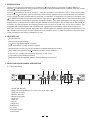
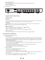
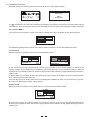
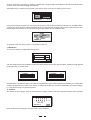
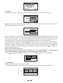
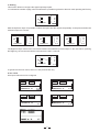
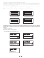
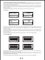
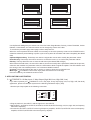
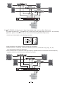
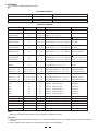
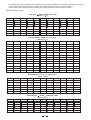
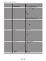
User's Manual
LTODRIVE3.4
3 WAY STEREO
DIGITAL X OVER
www.altoproaudio.com
Version 2.2 September 2005
English
Fuse
SAFETY RELATED SYMBOLS
To prevent fire and damage to the product, use only
the recommended fuse type as indicated in this
manual. Do not short-circuit the fuse holder. Before
replacing the fuse, make sure that the product is
OFF and disconnected from the AC outlet.
CAUTION
RISK OF ELECTRIC SHOCK
DO NOT OPEN
This symbol, wherever used, alerts you to the presence of un-insulated and dangerous voltages within the product enclosure. These are voltages that
may be sufficient to constitute the risk of electric
shock or death.
Protective Ground
Before turning the product ON, make sure that it is
connected to Ground. This is to prevent the risk of
electric shock.
This symbol, wherever used, alerts you to important operating and maintenance instructions.
Please read.
Never cut internal or external Ground wires. Likewise,
never remove Ground wiring from the Protective
Ground Terminal.
Protective Ground Terminal
Operating Conditions
AC mains (Alternating Current)
Always install in accordance with the manufacturer's
instructions.
Hazardous Live Terminal
ON:
To avoid the risk of electric shock and damage, do
not subject this product to any liquid/rain or moisture.
Do not use this product when in close proximity to
water.
Denotes the product is turned on.
OFF: Denotes the product is turned off.
WARNING
Do not install this product near any direct heat source.
Describes precautions that should be observed to
prevent the possibility of death or injury to the user.
Do not block areas of ventilation. Failure to do so
could result in fire.
CAUTION
Keep product away from naked flames.
Describes precautions that should be observed to
prevent damage to the product.
IMPORTANT SAFETY INSTRUCTIONS
Read these instructions
Disposing of this product should not be
placed in municipal waste and should be
Separate collection.
Follow all instructions
Keep these instructions. Do not discard.
Heed all warnings.
WARNING
Only use attachments/accessories specified by the
manufacturer.
Power Supply
Ensure that the mains source voltage (AC outlet)
matches the voltage rating of the product. Failure
to do so could result in damage to the product and
possibly the user.
Power Cord and Plug
Do not tamper with the power cord or plug. These are
designed for your safety.
Unplug the product before electrical storms occur
and when unused for long periods of time to reduce
the risk of electric shock or fire.
Do not remove Ground connections!
External Connection
Protect the power cord and plug from any physical
stress to avoid risk of electric shock.
If the plug does not fit your AC outlet seek advice from
a qualified electrician.
Always use proper ready-made insulated mains
cabling (power cord). Failure to do so could result
in shock/death or fire. If in doubt, seek advice from
a registered electrician.
Do not place heavy objects on the power cord. This
could cause electric shock or fire.
Cleaning
When required, either blow off dust from the product
or use a dry cloth.
Do Not Remove Any Covers
Within the product are areas where high voltages
may present. To reduce the risk of electric shock do
not remove any covers unless the AC mains power
cord is removed.
Do not use any solvents such as Benzol or Alcohol.
For safety, keep product clean and free from dust.
Servicing
Covers should be removed by qualified service
personnel only.
No user serviceable parts inside.
Refer all servicing to qualified service personnel only.
Do not perform any servicing other than those instructions contained within the User's Manual.
1
PREFACE
Dear Customer:
Thanks for choosing
researches.
For our
LTO DRIVE3.4 and thanks for choosing one of the results of
LTO AUDIO TEAM job and
LTO AUDIO TEAM , music and sound are more than a job... are first of all passion and let Us say our obsession!
We have been designing professional audio products for a long time in cooperation with some of the major brands in
the world in the audio field.
The LTO line presents unparalleled analogue and digital products made by Musicians for Musicians in our R&D
centers in Italy, Netherlands, United Kingdom and Taiwan. The core of our digital audio products is a sophisticated
DSP (digital sound processor) and a large range of state of the art algorithms which have been developed by our
Software Team for the last years.
Because we are convinced you are the most important member of LTO AUDIO TEAM and the one confirming the
quality of our job, we would like to share with you our work and our dreams, paying attention to your suggestions and
your comments.
Following this idea we create our products and we will create the new ones! From our side, we guarantee you and
we will guarantee you also in future the best quality , the best fruits of our continuous researches and the best prices.
Our LTO DRIVE3.4 is the result of many hours of listening and tests involving common people, area experts, musicians
and technicians; nothing else to add, but that we would like to thank all the people that made the LTO DRIVE3.4 a
reality available to our customers , and thank our designers and all the LTO staff, people who make possible the
realization of products containing our idea of music and sound and are ready to support you, our Customers, in the
best way , conscious that you are our best richness.
Thank you very much
LTO AUDIO TEAM
2
TABLE OF CONTENTS
1. INTRODUCTION ....................................................................................................................................4
2. FEATURE LIST ......................................................................................................................................4
3. FRONT AND BACK PANELS DESCRIPTION........................................................................................4
3.1 The Front Panel
3.2 The Rear Panel
4. INSTALLATION & CONNECTION .........................................................................................................5
4.1 Power Up and Audio Connections
a. Audio Connections
b. Power Up Setting
4.2 Operational Overview
4.2.1 UTILITY MENU
a. Load Preset
b. Store Preset
c. MIDI Setup
d. VU-Meter
e. Password
4.2.2 EDIT MENU
a. Routing
b. IN L/IN R
c. OUT 1 / 2 / 3 / 4 / 5 / 6
5. APPLICATION ILLUSTRATION...........................................................................................................12
5.1
LTODRIVE 3.4 2-Way Input, 6- Way Output (High, Mid, Low, Sub Level)
5.2
LTO DRIVE3.4 2-Way Input, 6- Way Output (High, High, Low, Low Level)
6. MIDI STANDARD CONTROL................................................................................................................14
7. TECHNICAL SPECIFICATIONS...........................................................................................................16
8. WARRANTY .........................................................................................................................................18
3
1. INTRODUCTION
Thank you very much for expressing your confidence in LTO products by purchasing our LTO DRIVE3.4.
With the LTO DRIVE3.4 you have acquired an extremely musical and flexible Active Crossover which will provide
you also the subwoofer application.
Our new LTO DRIVE 3.4(2 inputs , 6outputs , matrix-like operation X-over) allows the user to work with the quality
of the 2/3 by 24 32-bit DSPs, permits extremely precise and fast speakers control and equalization for PA systems
with the power of a matrix process allowing each kind of combination in assigning the 2 inputs to the 6 outputs. The
LTO DRIVE 3.4 is based on 2/3 extremely powerful , high-speed 24 32-bit DSP and very high quality 20-bit A/D and
24-bit D/A converters, preserving the pureness of analogue sound in your digital applications. The 128 64 graphical
display and the 14 buttons and the relative encoder available on the front panel, offer an easy way of editing data, so
to create new custom powerful and exciting presets which may then be stored in the unit as user's presets . The
integrated MIDI interface permits real-time editing with a powerful pc based SW or a MIDI standard sequencer.
Both input channels feature a digital, high quality filters 5-band parametric equalizer, allowing boost/attenuation of 15
dB in 0.5dB increment's steps. On each output channel is possible to have a 4t h order low pass and a high pass filters,
limiter /compressor and polarity switchable 0 or 180 .
2. FEATURE LIST
Single Rack Unit
Robust and Compact Design
24
32-bit High Speed Signal Processor
Open Architecture for Easy Software Updates
Windows Editor for Easy to Use and Powerful Pc Based MIDI Remote Control
Band Pass Filter Available (Until
24dB/Oct) for Each Output Channel
Up to 0.5 sec. of Delay per Channel by Step from 21 ms to 2ms
Lock-System for the Editing Functions
Manufactured Under QS9000, VDA6.1 Certified Management System.
3. FRONT AND BACK PANELS DESCRIPTION
3.1 The Front Panel
8
6
5
3
2
CLIP
-6
LTO DRIVE3.4
-12
R
LTO
UP
-18
ENTER
UTILITY
MUTE CH1
MUTE CH3
MUTE CH5
-24
ON
-30
LEFT
RIGHT
ESC
DOWN
13
12
OFF
EDIT
MUTE CH2
MUTE CH4
MUTE CH6
POWER
11 10 9
7
1.Power SW with LED
2.Mute buttons and LEDs for CH1, CH2, CH3, CH4, CH5, CH6
3.Utility key and LED
4.Edit key and LED
5.Dial knob(encoder)
6.Enter key
7.ESC key
8.Up key
9.Right key
10.Down key
11.Left key
12.Graphic display
13.Vu-meters
4
4
2
1
3-WAY STEREO
DIGITAL X-OVER
Power SW with LED (1)
Turns the apparatus on and off. Press this SW, the power LED inside the SW will turn on.
Dial Control knob (5)
Used to change editable values.
3.2.The Rear Panel
AC INPUT
95-240V 60-50Hz
Rated Power Consumption 15W
MODEL
PUSH
PUSH
NEW
NEW
MIDI
FUSE:
210-240V: T315mAL 250VAC
95-120V: 500mA 250VAC
REPLACE FUSE WITH CORRECT
TYPE ONLY
SERIAL
Apparaten skall anslutas till
jordat uttag nar den ansluts
CODE
till ett natverk
A102
TIDE
3
2
OUTPUT
17
THRU
INPUT
OUTPUT6
OUTPUT5
OUTPUT4
16
OUTPUT3
OUTPUT2
OUTPUT1
15
TIDE
3
1
2
INPUT2
1
INPUT1
14
14.Input Connector for Input1 and Input2
15.Output Connector for Output1~Output6
16.MIDI Connector
17.Power Connector
Inputs(14)
These are XLR balanced connectors which connect to sources such as the channel inserts on mixing consoles.
They may be used with nominal input levels from consumer to professional audio.
Outputs(15)
LTO DRIVE3.4 has 6 outputs, they are XLR balanced connectors which connect to devices such as
the channel inserts on mixing console or power amplifier inputs .
MIDI Connectors(16)
-MIDI in: 5-poles DIN connector for the MIDI input to the LTO DRIVE3.4.
-MIDI thr: 5-poles DIN connector for the MIDI thr.
-MIDI out: 5-poles DIN connector for the MIDI output from the LTO DRIVE3.4.
Power Connector(17)
This is an IEC 3-pole socket for connecting the AC power supply to the
LTO DRIVE3.4.
4. INSTALLATION & CONNECTION
4.1 Power Up and Audio Connections
a. Audio Connections
The connections between the LTO DRIVE3.4 and the other audio devices have to be made using high quality
cables so to prevent bad performances of the LTO DRIVE3.4 itself. So it should be good to use low-capacitance
shielded cables with a flexible internal conductor. Connect the cables to the LTO DRIVE3.4 properly by observing the following precautions:
Do not bundle audio cables with AC power cords.
Do not place audio cables and LTO DRIVE3.4 near sources of electromagnetic interference such as transformers, monitors, computers, etc.
Always unplug cables by firmly grasping the body of the plug and pulling directly outward.
Do not place cables where they can be stepped on.
Avoid twisting a cable or having it make sharp, right angle turns.
b. Power Up Setting
Before turning on the LTO DRIVE3.4's power, check if:
All connections have been made correctly.
The volume controls of the amplifier or mixer are turned down.
Insert the Power plug into the POWER input on the rear panel of the LTO DRIVE3.4 and plug the power cord
into an AC outlet.
Turn on the power of the LTO DRIVE3.4, pushing the ON/OFF button on the front panel.
Turn on the power of the amplifier/mixer, and adjust the volume.
5
4.2 Operational Overview
At system startup the following splash screens will be shown on the graphic display.
ALTO DRIVE3.4
Version1.0
Wait
Init System
The LTO DRIVE3.4 is booting and initializing its hardware and software, loading the last used preset and the
user interface. The process lasts a few seconds, afterwards the system goes to the Utility Menu (Utility Led is ON).
4.2.1 UTILITY MENU
The Utility menu is accessed by means of the Utility key (Utility Led is ON). The display shows as flowing figure:
UTILITY MENU
VU-M
LOAD
STORE
PASSW
MIDI
UNLOCK
PRESET 01
Use Up/Down/Left/Right keys to select one of the five fields. Use Enter to access the selected sub-menu.
a. Load Preset
With this function it's possible to load one of the 65 available presets.
LOAD
Name:
Num:
LOAD
PRESET
Name:
Num:
01
PRESET 01
1/1
PRESET
01
PRESET 01
1/1
In this window the user can read the name, number and type of the currently loaded preset. 1/1 indicates the
number of page; when it's selected it is possible to get back to the main menu pressing the Esc key. With the
Up/Down key it's possible to select the preset or page number fields, selection is high lighted printing the item in
reverse color.
To load a preset it is necessary to select the preset item; using the dial it is possible to choose the desired preset,
to be confirmed pressing the Enter key.
If the user tries to load an empty preset, an error message (NO LOADING) is shown for some seconds. To go back
to main menu, select page number, then press Esc.
b. Store Preset
With this function it's possible to store preset data into one of the 64 user available presets.
STORE
EMPTY
Name:
Num:
02
PRESET 01
1/1
In this window the user can read the number of the location in which to save the current preset data. With the Up/
Down key it's possible to select the preset or page number fields, selection is high lighted printing the item in
reverse color.
6
To save a preset it is necessary to select the Preset item; using the dial it is possible to choose the desired preset
number, to be confirmed pressing the Enter key.
After data saving, a character string (preset name) will be shown to the user for editing (max 8 chars).
STORE
EMPTY
Name:
Num:
02
1/1
PRESET 01
Using Left and Right keys the user can move into the string, with the dial the blinking character can be edited, Enter
confirms the choice and Esc cancels operation allowing to maintain the old preset name. Upon confirmation the new
preset name will be shown in the lower left corner of the window and in the Name field.
To get back to the main menu, select 1/1 and press the Esc key.
c. MIDI Setup
This function allows a simple MIDI configuration:
MIDI
CHANNEL
01
OUT EN.
OFF
1/1
PRESET 01
with the Up/Down key it's possible to select the MIDI channel and/or the output enable; selection is high lighted
printing the item in reverse color.
MIDI
MIDI
CHANNEL
01
CHANNEL
01
OUT EN.
OFF
OUT EN.
OFF
PRESET 01
1/1
PRESET 01
1/1
With the dial it is possible to change the value of the parameter, which will be operating immediately (no confirmation
needed). To get back to the main menu, select 1/1 and press the Esc key. These two parameters are system settings,
i.e. They don't belong to a particular preset.
d. VU-Meter
This sub-menu has 2 pages: the first (1/2) shows the 6 output volumes, the second (2/2) the activity of the 6 limiters.
CLIP
1 2 3 4 5 6
OUT VOL
PRESET 01
-30
1/2
Enter accesses the next page, Esc gets back to the precedent.
7
1 2 3 4 5 6
LIMITER
PRESET 01
2/2
e. Password
With this function the user can decide if the device has to be protected from unauthorized tampering:
PASSWORD
000000
NEW PASSWORD
PRESET 01
1/1
With the Up/Down key it's possible to select the Password, New Password and page number items; selection is
highlighted printing the item in reverse color.
PASSWORD
000000
NEW PASSWORD
PRESET 01
1/1
To have complete access to the system, the fields PASSWORD and NEW PASSWORD must match. If the user
wants to restrict system access, it is sufficient to change the PASSWORD field. In this condition the user is not able
to access UTILITY functions, except the PASSWORD screen. If the user wants to restore complete access to all
the system functions, it is sufficient to change the PASSWORD field again to match the other field.
If the two fields aren't matched, the NEW PASSWORD field results blank, in order to protect the system password;
when the two fields are matched, the NEW PASSWORD content becomes visible and therefore may be changed,
allowing to change the system password; to change a password, select the character string, use Left/Right keys
to select a character and change the character using the dial. The default password when the LTO DRIVE3.4 is
shipped is 000000 (all zeros).
Never forget the system password!
If you forget the system password you will be unable to unlock your LTO DRIVE3.4; a lost password Is
unrecoverable. Consult your LTO dealer in order to restore and unlock the system.
When the
LTO DRIVE3.4 is password protected, the LOCK indication appears on screen (see below).
UTILITY MENU
VU-M
LOAD
STORE
PASSW
MIDI
LOCK
PRESET 01
4.2.2 EDIT MENU
Edit key gives access to this menu (Edit LED is ON).
Use Up/Down/Left/Right keys to select one of the seven fields. Use Enter to access the selected sub-menu.
EDIT MENU
ROUT
OUT 1 OUT 4
IN L
OUT 2 OUT 5
OUT 3 OUT 6
IN R
PRESET 01
8
a. Routing
This function allows to configure the signal input/output path:
1/1 indicates the number of page; when it's selected it is possible to get back to the main menu pressing the Esc key.
ROUTING
1
2
3
4
5
6
L
IN
R
PRESET 01
O
U
T
1/1
With the Up/Down keys it is possible to select the inputs and the outputs sequentially. In the pictures below the
selection sequence is shown.
ROUTING
1
2
3
4
5
6
L
IN
R
PRESET 01
ROUTING
L
IN
R
O
U
T
PRESET 01
1/1
ROUTING
1
2
3
4
5
6
L
IN
R
O
U
T
PRESET 01
1/1
1
2
3
4
5
6
O
U
T
1/1
The Right/Left keys make/cut the connection between the selected input and output. In the case above, pressing
the Right key, the Left channel will be connected to the OUT 3 channel.
ROUTING
1
2
3
4
5
6
L
IN
R
PRESET 01
O
U
T
1/1
To get back to the main menu, select 1/1 and press the Esc key.
b. IN L / IN R
Here input channels can be configured:
PEQ 01
F: 20
PRESET 01 IL
PEQ 01
F: 20
PEQ 01
F: 20
G: 00.0
B: 0.15
PRESET 01 IL
1/2
PEQ 01
F: 20
G: 00.0
B: 0.15
PRESET 01 IL
G: 00.0
B: 0.15
G: 00.0
B: 0.15
PRESET 01 IL
1/2
9
1/2
1/2
This graphic screen shows the frequency response of the channel.
Use Up/Down/Left/Right keys to select one of the five fields: Page Number, Filter Number, Gain, Frequency, Bandwidth. The selected value can be changed by means of the dial. The selected filter's frequency will be shown by a
vertical segment on the display (see above).
When a filter parameter is modified, the audio signal is processed real-time, while the picture on the display waits
briefly to update. During this waiting time, an asterisk is shown in the upper right corner of the window, until the
graphic is processed.
To access the following screen select page number and press Enter, to get back press Esc.
DLY. A
000 ms
DLY. A
000 ms
DLY. F
0000 us
DLY. F
0000 us
VOL.
0.00 dB
PRESET 01 IL
2/2
VOL.
0.00 dB
PRESET 01 IL
2/2
DLY. A
000 ms
DLY. A
000 ms
DLY. F
0000 us
DLY. F
0000 us
VOL.
0.00 dB
PRESET 01 IL
2/2
VOL.
0.00 dB
PRESET 01 IL
2/2
Use Up/Down/Left/Right keys to select one of the four fields: Page Number, Volume, Delay Fine, Delay Adjust; the
selected value can be changed by means of the dial. To access the precedent screen select page number and
press Esc.
c. OUT 1 / 2 / 3 / 4 / 5 / 6
Here output channels can be configured:
EDIT PARAMETRIC FILTERS (page 1 of 4)
PEQ 01
F: 20
PRESET 01 O1
PEQ 01
F: 20
PEQ 01
F: 20
1/4
10
1/4
G: 00.0
B: 0.15
PRESET 01 O1
1/4
G: 00.0
B: 0.15
PRESET 01 O1
G: 00.0
B: 0.15
PRESET 01 O1
1/4
G: 00.0
B: 0.15
PRESET 01 O1
PEQ 01
F: 20
PEQ 01
F: 20
G: 00.0
B: 0.15
1/4
This graphic screen shows the frequency response of the channel.
Use Up/Down/Left/Right keys to select one of the five fields: Page Number, Filter Number, Gain, Frequency, Bandwidth. The selected value can be changed by means of the dial. The selected filter's frequency will be shown by a
vertical segment on the display (see above).
When a filter parameter is modified, the audio signal is processed real-time, while the picture on the display waits
briefly to update. During this waiting time, an asterisk is shown in the upper right corner of the window, until the
graphic is processed.
To access the following page select page number and press Enter. Esc returns to main menu.
EDIT HP/LP
HF: 21
LF:20K0
ORD: 0
ORD: 0
PRESET 01 O1
HF: 21
LF:20K0
HF: 21
LF:20K0
PRESET 01 O1
2/4
ORD: 0
ORD: 0
PRESET 01 O1
ORD: 0
ORD: 0
HF: 21
LF:20K0
ORD: 0
ORD: 0
PRESET 01 O1
2/4
2/4
2/4
Use Up/Down/Left/Right keys to select one of the five fields; Page Number, Freq Low Pass, Order Low Pass, Freq
High Pass, Order High Pass. Hi Pass and Low Pass filters are of Butterworth type; the selected value can be changed
by means of the dial.
When a filter parameter is modified, the audio signal is processed real-time, while the picture on the display waits
briefly to update. During this waiting time, an asterisk is shown in the upper right corner of the window, until the
graphic is processed.
To access the following page select page number and press Enter. Esc returns to precedent page.
EDIT PARAMETERS
DLY. A
000 ms
DLY. A
000 ms
DLY. F
0000 us
DLY. F
0000 us
VOL.
0.00 dB
PRESET 01 O1
3/4
VOL.
0.00 dB
PRESET 01 O1
3/4
DLY. A
000 ms
DLY. A
000 ms
DLY. F
0000 us
DLY. F
0000 us
VOL.
0.00 dB
PRESET 01 01
3/4
VOL.
0.00 dB
PRESET 01 01
3/4
Use Up/Down/Left/Right keys to select one of the four fields: Page Number, Volume, Delay Fine, Delay Adjust; the
selected values can be changed by means of the dial.
When Outputs 5 and 6 are selected, only Page Number and Volume fields can be selected because these
outputs aren't provided with delay lines.
To access the following screen select page number and press Enter. Esc returns to precedent page.
11
POL.
DIR
THR.
00 dB
REL.
0.4 S
ATK.
0.05 S
PRESET 01 O1
4/4
POL.
DIR
THR.
00 dB
REL.
0.4 S
ATK.
0.05 S
PRESET 01 O1
4/4
POL.
DIR
THR.
00 dB
REL.
0.4 S
ATK.
0.05 S
PRESET 01 O1
4/4
POL.
DIR
THR.
00 dB
REL.
0.4 S
ATK.
0.05 S
PRESET 01 O1
4/4
POL.
DIR
THR.
00 dB
REL.
0.4 S
ATK.
0.05 S
PRESET 01 O1
4/4
Use Up/Down/Left/Right keys to select one of the five fields: Page Number, Polarity, Limiter Threshold, Limiter
Release, Limiter Attack; the selected values can be changed by means of the dial.
To access the precedent page select page number and press Esc.
When the current preset has been edited, it is necessary to save this preset by means of the STORE function,
otherwise whatever preset loading or power cycle of the system will overwrite and erase Completely the edited
data.
Up/Down/Right/Left key: These keys are used to navigate the menus and to modify the parameter values.
Enter/Esc key: These keys are used to access or to leave the menus, or to confirm the parameter values.
Edit key: This key allows the user to enter the edit menu (the related LED will light)
When entered the edit menu, the user will be able to access and modify all the parameters related to the process,
when the user modifies one parameter value, the LED starts to blink to signal the update. The LED will blink until
the storing of the new modified preset in one of the 64 available locations.
Vu-meter: This function allows the user to use the vu-meter to show the input signal level.
Mute keys: LTO DRIVE3.4 has 6 mute keys.(each channel has one mute key).
Press the mute key, the related channel is muted.
5. APPLICATION ILLUSTRATION
5.1
LTODRIVE 3.4 2-Way Input, 6- Way Output (High, Mid, Low, High, Mid, Low)
If you want to present your LTODRIVE 3.4 in a 2-way input, 6-way output (high, mid, low, high, mid, low level)
application, please connect your system as the following illustration step by step:
1.Set the input /output path as the following connection:
ROUTING
L
IN
R
PRESET 01
1
2
3
4
5
6
O
U
T
1/1
2.Plug the left line-in into INPUT1 and the right line-in into INPUT2
3.Set OUTPUT1, OUTPUT2, OUTPUT3, OUTPUT4, OUTPUT5,OUTPUT6 as high, mid, low, high, mid, low frequency
band OUT separately.
4.Connect the OUTPUT1,OUTPUT4 to the high frequency amplifier, OUTPUT2,OUTPUT5 to the mid frequency
amplifier, OUTPUT3,OUTPUT6 to the low frequency amplifier.
12
LOW AMP
PROFESSIONAL HIGH POWER STEREO AMPLIFIER
PROT
CLIP
SIG
CLIP
SIG
ON
R
LTO
OFF
POWER
CH-A
CH-B
MID AMP
PROFESSIONAL HIGH POWER STEREO AMPLIFIER
PROT
CLIP
SIG
CLIP
SIG
ON
R
LTO
OFF
POWER
CH-A
CH-B
HIGH AMP
PROFESSIONAL HIGH POWER STEREO AMPLIFIER
PROT
SIG
CLIP
CLIP
SIG
ON
R
LTO
OFF
CH-A
POWER
PUSH
CH-B
PUSH
MIDI
AC INPUT
95-240V~60-50Hz
Rated Power Consumption 15W
FUSE:
NEW
MODEL
210-240V: T250mAL 250VAC
95-120V: 500mA 250VAC
REPLACE FUSE WITH CORRECT
TYPE ONLY
TIDE
NEW
3
OUTPUT
THRU
INPUT
OUTPUT6
OUTPUT5
OUTPUT4
OUTPUT3
OUTPUT2
OUTPUT1
TIDE
3
2
1
INPUT2
2
1
INPUT1
MIXER
Apparaten skall anslutas till SERIAL
jordat uttag nar den ansluts
till ett natverk
LTO DRIVE3.4 2-Way Input, 6- Way Output (High, High, Low, Low, Sub, Sub Level)
If you want to present your LTO DRIVE3.4 in a 2-way input, 6-way output (high, high, low, low, sub, sub level)
application, please connect the unit to your system as the following illustration step by step:
1.Set the input /output path as the following connection:
ROUTING
1
2
3
4
5
6
L
IN
R
PRESET 01
O
U
T
1/1
2.Plug the left line-in into INPUT1and the right line-in into INPUT2.
3.Set the OUTPUT1, OUTPUT2, OUTPUT3, OUTPUT4,OUTPUT5, OUTPUT6 as high, high, low, low,
sub, sub frequency band OUT separately.
4.Connect the OUTPUT1, OUTPUT2 to the high frequency amplifier,OUTPUT3, OUTPUT4 to the low frequency
amplifier, OUTPUT5, OUTPUT6 to the low frequency amplifier.
SUB AMP
LOW AMP
HIGH AMP
PUSH
PUSH
MIDI
AC INPUT
95-240V~60-50Hz
Rated Power Consumption 15W
FUSE:
NEW
MODEL
210-240V: T250mAL 250VAC
95-120V: 500mA 250VAC
REPLACE FUSE WITH CORRECT
TYPE ONLY
Apparaten skall anslutas till SERIAL
jordat uttag nar den ansluts
till ett natverk
TIDE
NEW
3
2
OUTPUT
THRU
INPUT
OUTPUT6
OUTPUT5
OUTPUT4
OUTPUT3
MIXER
5.2
13
OUTPUT2
OUTPUT1
TIDE
3
1
INPUT2
2
1
INPUT1
6. APPENDIX
LTO DRIVE3.4 Midi standard control
PROGRAM CHANGE
Parameter
Value
Legend
0
Preset Factory
Preset 01
Preset 02 to preset 64
1, 2, 3,......, 64
Preset User
CONTROL CHANGE
Parameter
Controller
Value
0
0, 1, 2
Mode Channel
22
0, 1
Mode Channel
22
Output Volume
7
0,..., 48
High Pass Filter
17
0,..., 120
Bank
setting
Legend
Input Left, Input Right
2, 3, 4, 5, 6, 7 Output 1, 2, 3, 4, 5, 6
Select Mode Channel
12 /
12 dB
Mode Channel = 2, 3, 4, 5, 6, 7 Bank=0 HP Frequency
High Pass Filter
17
Low Pass Filter
18
0, 1, 2, 3, 4 Mode Channel = 2, 3, 4, 5, 6, 7 Bank=1 HP Order
Low Pass Filter
18
Delay Line Adj
19
0,..., 127
Mode Channel = 0, 1, 2, 3, 4, 5 Bank=0 508 ms step 4ms
Delay Line Fine
19
0,..., 95
Mode Channel = 0, 1, 2, 3, 4, 5 Bank=1 1995 us step 21us
Limiter Threshold
20
0,..., 29
Mode Channel = 2, 3, 4, 5, 6, 7 Bank=0
Limiter Release
20
0,..., 3
Mode Channel = 2, 3, 4, 5, 6, 7 Bank=1 0.4s, 0.5s, 0.7s, 1.4s
Limiter Attack
20
0,..., 3
Mode Channel = 2, 3, 4, 5, 6, 7 Bank=2 0.05s, 0.1s, 0.2s, 0.3s
Polarity
21
0
Mode Channel = 2, 3, 4, 5, 6, 7
Direct
Polarity
21
1
Mode Channel = 2, 3, 4, 5, 6, 7
Invers
Filer 01, 02,..., 04
12, 13, 14, 15
0,..., 120
Only Mode Channel = 0, 1 (in L, R)
Frequency; Bank=0
Filer 01, 02,..., 04
12, 13, 14, 15
0,..., 60
Only Mode Channel = 0, 1 (in L, R)
Amplitude; Bank=1
0,..., 120
Mode Channel = 2, 3, 4, 5, 6, 7 Bank=0 LP Frequency
0, 1, 2, 3, 4 Mode Channel = 2, 3, 4, 5, 6, 7 Bank=1 LP Order
29, ..., 0dB
Filer 01, 02,..., 04
12, 13, 14, 15
0,..., 59
Only Mode Channel = 0, 1 (in L, R)
Band Width; Bank=2
Filer 01, 02,..., 05
12, 13, 14, 15, 16
0,..., 120
Only Mode Channel = 2, 3, 4, 5, 6, 7
Frequency; Bank=0
Filer 01, 02,..., 05
12, 13, 14, 15, 16
0,..., 60
Only Mode Channel = 2, 3, 4, 5, 6, 7
Amplitude; Bank=1
Filer 01, 02,..., 05
12, 13, 14, 15, 16
0,..., 59
Only Mode Channel = 2, 3, 4, 5, 6, 7
Band Width; Bank=2
Mute
23
0, 1
Output 1
Mute OFF, ON
ModeCh=2
Mute
23
0, 1
Output 2
Mute OFF, ON
ModeCh=3
Mute
23
0, 1
Output 3
Mute OFF, ON
ModeCh=4
Mute
23
0, 1
Output 4
Mute OFF, ON
ModeCh=5
Mute
23
0, 1
Output 6
Mute OFF, ON
ModeCh=6
Mute
23
0, 1
Output 5
Mute OFF, ON
ModeCh=7
Routing
24
0, 1
Connect Off/On InputL/R to Output1
Bank= 0 / Bank=1
Routing
25
0, 1
Connect Off/On InputL/R to Output2
Bank= 0 / Bank=1
Routing
26
0, 1
Connect Off/On InputL/R to Output3
Bank= 0 / Bank=1
Routing
27
0, 1
Connect Off/On InputL/R to Output4
Bank= 0 / Bank=1
Routing
28
0, 1
Connect Off/On InputL/R to Output5
Bank= 0 / Bank=1
Routing
29
0, 1
Connect Off/On InputL/R to Output6
Bank= 0 / Bank=1
Note:
Select the channel to edit by means of the controller 22 (Mode channel).
Warnings:
1. Before starting a MIDI session please set on the ALTO DRIVE3.4 the same MIDI channel used by the external
controller.
2. During a MIDI control session the unit's graphic display is NOT updated.
14
3. After MIDI use of ALTO DRIVE3.4 it's advisable to run a manual STORE to save preset changes done by means
of the external controller. After saving, reboot the ALTO DRIVE3.4 to use it as a stand-along unit.
4. When setting and resetting mutes (controller 23) by MIDI, the relative LEDs are NOT actived.
MIDI Controllers Values
Amplitude
d\u
0
1
2
15dB / 15dB step 0.5dB
(Value = d u)
3
4
5
6
7
8
9
0
15.0dB
14.5dB
14.0dB
13.5dB
13.0dB
12.5dB
12.0dB
11.5dB
11.0dB
10.5dB
10
10.0dB
09.5dB
09.0dB
08.5dB
08.0dB
07.5dB
07.0dB
06.5dB
06.0dB
05.5dB
20
05.0dB
04.5dB
04.0dB
03.5dB
03.0dB
02.5dB
2.0dB
1.5dB
1.0dB
00.5dB
30
00.0dB
00.5dB
01.0dB
01.5dB
02.0dB
02.5dB
03.0dB
03.5dB
04.0dB
04.5dB
40
05.0dB
05.5dB
06.0dB
06.5dB
07.0dB
07.5dB
08.0dB
08.5dB
09.0dB
09.5dB
50
10.0dB
10.5dB
11.0dB
11.5dB
12.0dB
12.5dB
13.0dB
13.5dB
14.0dB
14.5dB
60
15.0dB
Frequency 20Hz - 20KHz step 1/12 oct
(Value = d u)
d\u
0
1
2
0
20
21,2
10
35,8
20
63
30
3
4
5
6
22,5
23,7
25
26,6
37,9
40
42,5
45
67
71,5
76
80
113
119
125
134
40
200
212,5
225
50
358
379
60
630
70
7
8
9
28,3
29,9
31,5
33,6
47,5
50
53,5
57
59,5
85
90
95
100
106,5
143
151,5
160
170
180
190
237,5
250
266,5
283
299
315
336,5
400
425
450
475
500
532,5
565
597,5
672,5
715
757,5
800
850
900
950
1000
1062
1125
1187
1250
1337
1425
1512
1600
1700
1800
1900
80
2000
2125
2250
2375
2500
2662
2825
2987
3150
3362
90
3575
3787
4000
4250
4500
4750
5000
5325
5650
5975
100
6300
6725
7150
7575
8000
8500
9000
9500
10000
10625
110
11250
11875
12500
13375
14250
15125
16000
17000
18000
19000
120
20000
7
8
9
Bandwidth 0.05 oct - 3 oct step 0.05 oct
(Value = d u)
d\u
0
1
2
3
4
5
6
0
0,05
0,1
0,15
0,2
0,25
0,3
0,35
0,4
0,45
0,5
10
0,55
0,6
0,65
0,7
0,75
0,8
0,85
0,9
0,95
1
20
1,05
1,1
1,15
1,2
1,25
1,3
1,35
1,4
1,45
1,5
30
1,55
1,6
1,65
1,7
1,75
1,8
1,85
1,9
1,95
2
40
2,05
2,1
2,15
2,2
2,25
2,3
2,35
2,4
2,45
2,5
50
2,55
2,6
2,65
2,7
2,75
2,8
2,85
2,9
2,95
3
Output Volume
d\u
0
1
2
12dB / 12dB step 0.5dB
(Value = d u)
3
4
5
6
7
8
9
0
12.0dB
11.5dB
11.0dB
10.5dB
10.0dB
09.5dB
09.0dB
08.5dB
08.0dB
07.5dB
10
07.0dB
06.5dB
06.0dB
05.5dB
05.0dB
04.5dB
04.0dB
03.5dB
03.0dB
02.5dB
20
2.0dB
1.5dB
1.0dB
00.5dB
00.0dB
00.5dB
01.0dB
01.5dB
02.0dB
02.5dB
30
03.0dB
03.5dB
04.0dB
04.5dB
05.0dB
05.5dB
06.0dB
06.5dB
07.0dB
07.5dB
40
08.0dB
08.5dB
09.0dB
09.5dB
10.0dB
10.5dB
11.0dB
11.5dB
12.0dB
15
7. TECHNICAL SPECIFICATIONS
Input Channel
Digital Input Gain
/+ 12 dB / step 0.5 dB
Gain /+ 15 dB / step 0.5 dB
Freq 20 Hz 20 KHz step 1/12 oct
BandWidth 0.05 oct 3 oct / step 0.05 oct
Up to 512 ms minimum step 21us
4 Parametric Filters
Delay line
Output Channel
Digital Out Volume
Delay line
/+ 12 dB / step 0.5 dB
Up to 512 ms minimum step 21us
Gain /+ 15 dB / step 0.5dB
5 Parametric Filters
Freq 20 Hz - 20 KHz / step 1/12 oct
BandWidth 0.05 oct - 3 oct step 0.05 oct
High Pass filter type Butterworth
Freq: 20 Hz - 20 KHz / step 1/12 oct
Slope: Bypass, 1st ord,2 ndord, 3 rd ord, 4 th ord
Low Pass filter type Butterworth
Freq:20 Hz - 20 KHz / step 1/12 oct
Slope: Bypass, 1st ord,2 ndord, 3 rd ord, 4 th ord
Polarity
Phase 0 or 180
Threshold 29 dB up to 0 dB / step 1dB
Limiter
Release Time 0.4 s, 0.5 s, 0.7 s, 1.4 s
Attack Time 0.05 s, 0.10 s, 0.20 s, 0.30 s
The Whole Unit
Memory
1 Factory Preset
64 User Preset
Analog
Inputs
Outputs
Input Impedance
Output Impedance
2 XLR - F (BAL)
6 XLR - M (BAL)
>40k
<200
Input MAX Level
Output MAX Level
A/D Converter
D/A Converter
Performance
12dBv
12dBv
20BITS Sigma-Delta
24BITS Sigma-Delta
THD+N
Amplitude
S/N Ratio
Digital
0.02
Processor speed
DSP resolution
Control
MIDI section
36 MIPs
24 32 bits
Microprocessor
Connections
Input/output/thru
Sockets
5
Mode
Photocoupled
(1KHz
3dBFS)
20Hz 20KHz
>97dBa
16
poles DIN(female)
Power Supply
Connector type
Type
3 poles DIN (female)
Servo controlled, Switching
fuse
AC Input
210 240V: T250mAL 250VAC
95 120V: 500mAL 250VAC
95 240V~60 50Hz
rated power consumption
15W
Graphic display
Keyboard
Vu meter
128 64 dots
14 user keys/ 8LEDs
2 6 LEDs
Size
Standard 19"rack Mounting
Dimensions
weight
483(W) 232.5(D)
3.5Kg(7.72lb)
User Interface
Physical
17
44(H)mm(19"
9.3"
1.7")
8. WARRANTY
1. WARRANTY REGISTRATION CARD
To obtain Warranty Service, the buyer should first fill out and return the enclosed Warranty Registration Card within
10 days of the Purchase Date.
All the information presented in this Warranty Registration Card gives the manufacturer a better under-standing of
the sales status, so as to purport a more effective and efficient after-sales warranty service. Please fill out all the
information carefully and genuinely, miswriting or absence of this card will void your warranty service.
2. RETURN NOTICE
2.1 In case of return for any warranty service, please make sure that the product is well packed in its original shipping
carton, and it can protect your unit from any other extra damage.
2.2 Please provide a copy of your sales receipt or other proof of purchase with the returned machine ,and give detail
information about your return address and contact telephone number .
2.3 A brief description of the defect will be appreciated.
2.4 Please prepay all the costs involved in the return shipping, handling and insurance.
3. TERMS AND CONDITIONS
3.1
LTO warrants that this product will be free from any defects in materials and/or workmanship for a period of 1
year from the purchase date if you have completed the Warranty Registration Card in time.
3.2 The warranty service is only available to the original consumer, who purchased this product directly from the
retail dealer, and it can not be transferred.
3.3 During the warranty service, LTO may repair or replace this product at its own option at no charge to you for
parts or for labor in accordance with the right side of this limited warranty.
3.4 This warranty does not apply to the damages to this product that occurred as the following conditions:
Instead of operating in accordance with the user's manual thoroughly, any abuse or misuse of this product.
Normal tear and wear.
The product has been altered or modified in any way.
Damage which may have been caused either directly or indirectly by another product / force / etc
Abnormal service or repairing by anyone other than the qualified personnel or technician.
And in such cases, all the expenses will be charged to the buyer.
3.5 In no event shall LTO be liable for any incidental or consequential damages. Some states do not allow the
exclusion or limitation of incidental or consequential damages, so the above exclusion or limitation may not apply
to you.
3.6 This warranty gives you the specific rights, and these rights are compatible with the state laws, you may also
have other statutory rights that may vary from state to state.
18
SEIKAKU TECHNICAL GROUP LIMITED
No. 1, Lane 17, Sec. 2, Han Shi West Road, Taichung 40151 Taiwan
http://www.altoproaudio.com Tel: 886-4-22313737
email: [email protected] Fax: 886-4-22346757
All rights reserved to ALTO. All features and content might be changed
without prior notice. Any photocopy, translation, or reproduction of part of this
manual without written permission is forbidden. Copyright c 2005 SEIKAKU GROUP
NF 01201-2.2