1
To resize thickness, move all items on the front cover
and center registration marks to left or right.
*
0
4
8
9
7
8
6
7
-
0
3
*
04897867
08-08-3N
To resize thickness, move all items on the front cover
and center registration marks to left or right.
For the U.K.
For EU Countries
IMPORTANT: THE WIRES IN THIS MAINS LEAD ARE COLOURED IN ACCORDANCE WITH THE FOLLOWING CODE.
CAUTION
Danger of explosion if battery is
incorrectly replaced.
Replace only with the same or
equivalent type recommended by the
manufacturer.
Discard used batteries according to the
manufacturer’s instructions.
Apparatus containing
Lithium batteries
ADVARSEL!
BLUE:
NEUTRAL
BROWN: LIVE
As the colours of the wires in the mains lead of this apparatus may not correspond with the coloured markings identifying
the terminals in your plug, proceed as follows:
The wire which is coloured BLUE must be connected to the terminal which is marked with the letter N or coloured BLACK.
The wire which is coloured BROWN must be connected to the terminal which is marked with the letter L or coloured RED.
Under no circumstances must either of the above wires be connected to the earth terminal of a three pin plug.
VARNING
Lithiumbatteri - Eksplosionsfare ved
fejlagtig håndtering.
Udskiftning må kun ske med batteri af
samme fabrikat og type.
Levér det brugte batteri tilbage til
leverandøren.
Explosionsfara vid felaktigt batteribyte.
Använd samma batterityp eller en
ekvivalent typ som rekommenderas av
apparattillverkaren.
Kassera använt batteri enligt
fabrikantens instruktion.
ADVARSEL
VAROITUS
Eksplosjonsfare ved feilaktig skifte av
batteri.
Benytt samme batteritype eller en
tilsvarende type anbefalt av
apparatfabrikanten.
Brukte batterier kasseres i henhold til
fabrikantens instruks joner.
Paristo voi räjähtää, jos se on
virheellisesti asennettu.
Vaihda paristo ainoastaan
laitevalmistajan suosittelemaan
tyyppiin. Hävitä käytetty paristo
valmistajan ohjeiden mukaisesti.
For C.A. US (Proposition 65)
For EU Countries
WARNING
This product complies with the requirements of European Directive 89/336/EEC.
This product contains chemicals known to cause cancer, birth defects and other reproductive harm, including lead.
For the USA
FEDERAL COMMUNICATIONS COMMISSION
RADIO FREQUENCY INTERFERENCE STATEMENT
For the USA
This equipment has been tested and found to comply with the limits for a Class B digital device, pursuant to Part 15 of the
FCC Rules. These limits are designed to provide reasonable protection against harmful interference in a residential
installation. This equipment generates, uses, and can radiate radio frequency energy and, if not installed and used in
accordance with the instructions, may cause harmful interference to radio communications. However, there is no guarantee
that interference will not occur in a particular installation. If this equipment does cause harmful interference to radio or
television reception, which can be determined by turning the equipment off and on, the user is encouraged to try to correct the
interference by one or more of the following measures:
– Reorient or relocate the receiving antenna.
– Increase the separation between the equipment and receiver.
– Connect the equipment into an outlet on a circuit different from that to which the receiver is connected.
– Consult the dealer or an experienced radio/TV technician for help.
This device complies with Part 15 of the FCC Rules. Operation is subject to the following two conditions:
(1) This device may not cause harmful interference, and
(2) This device must accept any interference received, including interference that may cause undesired operation.
Unauthorized changes or modification to this system can void the users authority to operate this equipment.
This equipment requires shielded interface cables in order to meet FCC class B Limit.
DECLARATION OF CONFORMITY
Compliance Information Statement
Model Name :
Type of Equipment :
Responsible Party :
Address :
Telephone :
R-44
4-CHANNEL PORTABLE RECORDER and WAVE EDITOR
Roland Systems Group U.S.
425 Sequoia Drive Suite 114, Bellingham, Washington, 98226 USA
360-594-4282
204
*
Microsoft and Windows are registered trademarks of Microsoft Corporation.
206j
*
Windows® is known officially as: “Microsoft® Windows® operating system.”
207
*
Apple and Macintosh are registered trademarks of Apple Inc.
209
*
Mac OS is a trademark of Apple Inc.
220
*
For Canada
All product names mentioned in this document are trademarks or registered trademarks of their respective owners.
ADD
*
SDHC Logo is a trademark
NOTICE
This Class B digital apparatus meets all requirements of the Canadian Interference-Causing Equipment Regulations.
236
AVIS
Cet appareil numérique de la classe B respecte toutes les exigences du Règlement sur le matériel brouilleur du Canada.
2
*
Fugue © 2008 Kyoto Software Research, Inc. All rights reserved.
fig.Fugue-logo.eps
4AGAPGYDQQMࡍࠫ㧞㧜㧜㧤ᐕ㧡㧝㧡ᣣᦐᧁޓᣣޓඦᓟ㧠ᤨ㧡㧟ಽ
USING THE UNIT SAFELY
002c
•
Do not open (or modify in any way) the unit or its
AC adaptor.
009
•
................................................................................................
003
•
Do not attempt to repair the unit, or replace parts
within it (except when this manual provides
specific instructions directing you to do so). Refer
all servicing to your retailer, the nearest Roland Service
Center, or an authorized Roland distributor, as listed on
the “Information” page.
................................................................................................
010
•
................................................................................................
004
•
Never use or store the unit in places that are:
• Subject to temperature extremes (e.g., direct
sunlight in an enclosed vehicle, near a heating
duct, on top of heat-generating equipment); or
are
Do not excessively twist or bend the power cord,
nor place heavy objects on it. Doing so can damage
the cord, producing severed elements and short
circuits. Damaged cords are fire and shock hazards!
This unit, either alone or in combination with an
amplifier and headphones or speakers, may be
capable of producing sound levels that could cause
permanent hearing loss. Do not operate for a long period
of time at a high volume level, or at a level that is
uncomfortable. If you experience any hearing loss or
ringing in the ears, you should immediately stop using the
unit, and consult an audiologist.
................................................................................................
011
•
• Damp (e.g., baths, washrooms, on wet floors); or are
Do not allow any objects (e.g., flammable material,
coins, pins); or liquids of any kind (water, soft
drinks, etc.) to penetrate the unit.
• Humid; or are
• Exposed to rain; or are
• Dusty; or are
• Subject to high levels of vibration.
................................................................................................
012b
•
................................................................................................
007
•
Make sure you always have the unit placed so it is
level and sure to remain stable. Never place it on
stands that could wobble, or on inclined surfaces.
Immediately turn the power off, remove the AC
adaptor from the outlet, and request servicing by
your retailer, the nearest Roland Service Center, or an
authorized Roland distributor, as listed on the
“Information” page when:
................................................................................................
• The AC adaptor, the power-supply cord, or the plug
has been damaged; or
•
• If smoke or unusual odor occurs
008c
Be sure to use only the AC adaptor supplied with
the unit. Also, make sure the line voltage at the
installation matches the input voltage specified on
the AC adaptor’s body. Other AC adaptors may use a
different polarity, or be designed for a different voltage, so
their use could result in damage, malfunction, or electric
shock.
................................................................................................
008e
•
Use only the attached power-supply cord. Also, the
supplied power cord must not be used with any
other device.
• Objects have fallen into, or liquid has been spilled onto
the unit; or
• The unit has been exposed to rain (or otherwise has
become wet); or
• The unit does not appear to operate normally or
exhibits a marked change in performance.
................................................................................................
014
•
Protect the unit from strong impact.
(Do not drop it!)
3
4AGAPGYDQQMࡍࠫ㧞㧜㧜㧤ᐕ㧡㧝㧡ᣣᦐᧁޓᣣޓඦᓟ㧠ᤨ㧡㧟ಽ
013
•
In households with small children, an adult should
provide supervision until the child is capable of
following all the rules essential for the safe operation of
the unit.
................................................................................................
015
•
Do not force the unit’s power-supply cord to share
an outlet with an unreasonable number of other
devices. Be especially careful when using extension
cords—the total power used by all devices you have
connected to the extension cord’s outlet must never
exceed the power rating (watts/amperes) for the
extension cord. Excessive loads can cause the insulation
on the cord to heat up and eventually melt through.
108b
•
................................................................................................
109b
•
•
Before using the unit in a foreign country, consult
with your retailer, the nearest Roland Service
Center, or an authorized Roland distributor, as listed on
the “Information” page.
................................................................................................
019
•
Batteries must never be recharged, heated, taken
apart, or thrown into fire or water.
................................................................................................
•
•
................................................................................................
•
If used improperly, batteries may explode or leak
and cause damage or injury. In the interest of
safety, please read and observe the following
precautions (p. 25).
1
• Carefully follow the installation instructions for
batteries, and make sure you observe the correct
polarity.
2
• Avoid using new batteries together with used ones. In
addition, avoid mixing different types of batteries.
3
• Remove the batteries whenever the unit is to remain
unused for an extended period of time.
5
• If a battery has leaked, use a soft piece of cloth or paper
towel to wipe all remnants of the discharge from the
battery compartment. Then install new batteries. To
avoid inflammation of the skin, make sure that none of
the battery discharge gets onto your hands or skin.
Exercise the utmost caution so that none of the
discharge gets near your eyes. Immediately rinse the
affected area with running water if any of the discharge
has entered the eyes.
6
• Never keep batteries together with metallic objects such
as ballpoint pens, necklaces, hairpins, etc.
Never expose lithium batteries/batteries to
excessive heat such as sunshine, fire or the like.
101b
•
The unit and the AC adaptor should be located so
their location or position does not interfere with
their proper ventilation.
................................................................................................
102c
•
Always grasp only the plug on the AC adaptor
cord when plugging into, or unplugging from, an
outlet or this unit.
................................................................................................
112
•
................................................................................................
103b
•
At regular intervals, you should unplug the AC
adaptor and clean it by using a dry cloth to wipe
all dust and other accumulations away from its
prongs. Also, disconnect the power plug from the power
outlet whenever the unit is to remain unused for an
extended period of time. Any accumulation of dust
between the power plug and the power outlet can result in
poor insulation and lead to fire.
•
Try to prevent cords and cables from becoming
entangled. Also, all cords and cables should be
placed so they are out of the reach of children.
................................................................................................
106
•
Never climb on top of, nor place heavy objects on
the unit.
................................................................................................
107c
•
4
Never handle the AC adaptor or its plugs with wet
hands when plugging into, or unplugging from, an
outlet or this unit.
Used batteries must be disposed of in compliance
with whatever regulations for their safe disposal
that may be observed in the region in which you
live.
................................................................................................
118a
•
Should you remove grounding terminal screw,
keep it in a safe place out of children’s reach, so
there is no chance of it being swallowed
accidentally.
................................................................................................
119
•
................................................................................................
104
Whenever you suspect the possibility of lightning
in your area, disconnect the AC adaptor from the
outlet.
111: Selection
................................................................................................
027
Before cleaning the unit, turn off the power and
unplug the AC adaptor from the outlet (p. 24).
110b
................................................................................................
016
Before moving the unit, disconnect the AC adaptor
and all cords coming from external devices.
The battery may become hot, so take care to avoid
burns.
................................................................................................
120
•
Always turn the phantom power off when
connecting any device other than condenser
microphones that require phantom power. You risk
causing damage if you mistakenly supply phantom power
to dynamic microphones, audio playback devices, or other
devices that don’t require such power. Be sure to check the
specifications of any microphone you intend to use by
referring to the manual that came with it.
This instrument’s phantom power: 48 V DC, 8 mA Max
(Total of all channels must be 25 mA or less)
4AGAPGYDQQMࡍࠫ㧞㧜㧜㧤ᐕ㧡㧝㧡ᣣᦐᧁޓᣣޓඦᓟ㧠ᤨ㧡㧟ಽ
IMPORTANT NOTES
291a
In addition to the items listed under “USING THE UNIT SAFELY” on page 3 and 4, please read and observe the following:
Power Supply: Use of Batteries
301
• Do not connect this unit to same electrical outlet that is
being used by an electrical appliance that is controlled by
an inverter (such as a refrigerator, washing machine,
microwave oven, or air conditioner), or that contains a
motor. Depending on the way in which the electrical
appliance is used, power supply noise may cause this unit
to malfunction or may produce audible noise. If it is not
practical to use a separate electrical outlet, connect a power
supply noise filter between this unit and the electrical
outlet.
302
• The AC adaptor will begin to generate heat after long
hours of consecutive use. This is normal, and is not a cause
for concern.
303a
• The use of an AC adaptor is recommended as the unit’s
power consumption is relatively high. Should you prefer to
use batteries, please use the alkaline type or nickel metal
hydride type.
304a
• When installing or replacing batteries, always turn off the
power on this unit and disconnect any other devices you
may have connected. This way, you can prevent
malfunction and/or damage to speakers or other devices.
307
• Before connecting this unit to other devices, turn off the
power to all units. This will help prevent malfunctions
and/or damage to speakers or other devices.
Placement
351
• Using the unit near power amplifiers (or other equipment
containing large power transformers) may induce hum. To
alleviate the problem, change the orientation of this unit; or
move it farther away from the source of interference.
352a
• This device may interfere with radio and television
reception. Do not use this device in the vicinity of such
receivers.
355b
• When moved from one location to another where the
temperature and/or humidity is very different, water
droplets (condensation) may form inside the unit. Damage
or malfunction may result if you attempt to use the unit in
this condition. Therefore, before using the unit, you must
allow it to stand for several hours, until the condensation
has completely evaporated.
360
• Depending on the material and temperature of the surface
on which you place the unit, its rubber feet may discolor or
mar the surface.
You can place a piece of felt or cloth under the rubber feet
to prevent this from happening. If you do so, please make
sure that the unit will not slip or move accidentally.
Maintenance
401a
• For everyday cleaning wipe the unit with a soft, dry cloth
or one that has been slightly dampened with water. To
remove stubborn dirt, use a cloth impregnated with a mild,
non-abrasive detergent. Afterwards, be sure to wipe the
unit thoroughly with a soft, dry cloth.
402
• Never use benzine, thinners, alcohol or solvents of any
kind, to avoid the possibility of discoloration and/or
deformation.
Repairs and Data
452
• Please be aware that all data contained in the unit’s
memory may be lost when the unit is sent for repairs.
Important data should always be backed up on a memory
card, or written down on paper (when possible). During
repairs, due care is taken to avoid the loss of data.
However, in certain cases (such as when circuitry related to
memory itself is out of order), we regret that it may not be
possible to restore the data, and Roland assumes no
liability concerning such loss of data.
352b
• Noise may be produced if wireless communications
devices, such as cell phones, are operated in the vicinity of
this unit. Such noise could occur when receiving or
initiating a call, or while conversing. Should you
experience such problems, you should relocate such
wireless devices so they are at a greater distance from this
unit, or switch them off.
354a
• Do not expose the unit to direct sunlight, place it near
devices that radiate heat, leave it inside an enclosed
vehicle, or otherwise subject it to temperature extremes.
Excessive heat can deform or discolor the unit.
5
4AGAPGYDQQMࡍࠫ㧞㧜㧜㧤ᐕ㧡㧝㧡ᣣᦐᧁޓᣣޓඦᓟ㧠ᤨ㧡㧟ಽ
IMPORTANT NOTES
Additional Precautions
551
• Please be aware that the contents of memory can be
irretrievably lost as a result of a malfunction, or the
improper operation of the unit. To protect yourself against
the risk of loosing important data, we recommend that you
periodically save a backup copy of important data you
have stored in the unit’s memory on a memory card.
552
• Unfortunately, it may be impossible to restore the contents
of data that was stored on a memory card once it has been
lost. Roland Corporation assumes no liability concerning
such loss of data.
553
• Use a reasonable amount of care when using the unit’s
buttons, sliders, or other controls; and when using its jacks
and connectors. Rough handling can lead to malfunctions.
554
• Never strike or apply strong pressure to the display.
555
• A small amount of noise may be heard from the display
during normal operation.
556
• When connecting / disconnecting all cables, grasp the
connector itself—never pull on the cable. This way you will
avoid causing shorts, or damage to the cable’s internal
elements.
558a
• To avoid disturbing your neighbors, try to keep the unit’s
volume at reasonable levels. You may prefer to use
headphones, so you do not need to be concerned about
those around you (especially when it is late at night).
559a
• When you need to transport the unit, package it in the box
(including padding) that it came in, if possible. Otherwise,
you will need to use equivalent packaging materials.
562
• Some connection cables contain resistors. Do not use cables
that incorporate resistors for connecting to this unit. The
use of such cables can cause the sound level to be
extremely low, or impossible to hear. For information on
cable specifications, contact the manufacturer of the cable.
Before Using Cards
Using Memory Cards
704
• Carefully insert the memory card all the way in—until it is
firmly in place.
705
• Never touch the terminals of the memory card. Also, avoid
getting the terminals dirty.
708
• Memory cards are constructed using precision
components; handle the cards carefully, paying particular
note to the following.
• To prevent damage to the cards from static electricity, be
sure to discharge any static electricity from your own body
before handling the cards.
• Do not touch or allow metal to come into contact with
the contact portion of the cards.
• Do not bend, drop, or subject cards to strong shock or
vibration.
• Do not keep cards in direct sunlight, in closed vehicles,
or other such locations (storage temperature: -25 to 85°
C).
• Do not allow cards to become wet.
• Do not disassemble or modify the cards.
Copyright
851
• Recording, duplication, distribution, sale, lease,
performance, or broadcast of copyrighted material
(musical works, visual works, broadcasts, live
performances, etc.) belonging to a third party in part or in
whole without the permission of the copyright owner is
forbidden by law.
852
• This product can be used to record or duplicate audio or
visual material without being limited by certain
technological copy-protection measures. This is due to the
fact that this product is intended to be used for the purpose
of producing original music or video material, and is
therefore designed so that material that does not infringe
copyrights belonging to others (for example, your own
original works) can be recorded or duplicated freely.
853
• Do not use this unit for purposes that could infringe on a
copyright held by a third party. We assume no
responsibility whatsoever with regard to any
infringements of third-party copyrights arising through
your use of this unit.
6
4AGAPGYDQQMࡍࠫ㧞㧜㧜㧤ᐕ㧡㧝㧡ᣣᦐᧁޓᣣޓඦᓟ㧠ᤨ㧡㧟ಽ
Contents
USING THE UNIT SAFELY...............3
IMPORTANT NOTES ......................5
Checking the Included Items.........8
Introducing the R-44 ....................9
Names of Things and What They Do................ 9
Display................................................................. 18
Projects................................................................. 22
Getting Ready to Use the R-44 ...24
Connecting the AC Adaptor and Turning the
Power On/Off .................................................... 24
Installing Batteries and Turning on
the Power............................................................. 25
Preparing the SD Memory Card ...................... 28
Manipulating a Project (Finder) .. 48
Selecting a Project (Select) ................................ 48
Renaming a Project (Rename) .......................... 49
Copying a Project (Copy) ................................. 50
Moving a Project (Move) .................................. 51
Deleting a Project (Delete) ................................ 52
Creating a New Folder (Make Folder)............ 53
Repairing a Project (Repair) ............................. 54
Setting the Color of Sound
(Effects Settings) ........................ 55
Applying Effects ................................................ 56
Effects .................................................................. 58
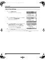
System Setup ............................ 60
Example Operations .......................................... 61
Recording ..................................29
Recording from a Connected Microphone ..... 29
Recording from the Internal Mics.................... 32
Recording Digital Audio from a
Digital Device ..................................................... 33
Simultaneously Recording Sound from
Connected Microphones and
a Digital Device .................................................. 34
Simultaneously Recording Sound from
Connected External Microphones and the
Internal Mics ....................................................... 36
Recording Digital Audio from
an Analog Device ............................................... 38
Simultaneously Recording Sound from
Connected Microphones and
an Analog Device ............................................... 39
Playing Back .............................41
Connections Before Playback ........................... 41
Connecting Headphones .................................41
Connecting Amplified Speakers.....................41
Connecting a Mixer or Other Analog
Device .................................................................41
Connecting a Device Having
a Digital Input Port...........................................42
Setup Before Playback ....................................... 43
Player Setup.......................................................43
Speaker Settings ................................................44
Playing Back........................................................ 45
Normal Playback ..............................................45
Markers ..............................................................46
Repeat Playback (A-B REPEAT) .....................47
Recording Setup................................................61
Date & Time Settings........................................62
Project Name Settings ......................................63
Formatting and Checking
the SD Memory Card .......................................64
Executing Factory Reset
(Restoring Factory Default Settings) ..............65
System Menu ...................................................... 66
Appendix .................................. 71
Connecting to a Computer ............................... 71
Connecting the R-44 to Your Computer........71
Disconnecting the R-44 from a Computer.....72
Remotely Linking Two Connected
R-44 Units............................................................ 73
Messages .................................. 74
Troubleshooting ........................ 75
Main Specifications.................... 79
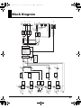
Block Diagram .......................... 81
Index ........................................ 82
01
Before using this unit, carefully read the sections
entitled: “USING THE UNIT SAFELY” and
“IMPORTANT NOTES” (p. 3–6). These sections
provide important information concerning the proper
operation of the unit. Additionally, in order to feel
assured that you have gained a good grasp of every
feature provided by your new unit, Owner’s Manual
should be read in its entirety. The manual should be
saved and kept on hand as a convenient reference.
202
Copyright © 2008 ROLAND CORPORATION
All rights reserved. No part of this publication may be
reproduced in any form without the written permission of
ROLAND CORPORATION.
7
4AGAPGYDQQMࡍࠫ㧞㧜㧜㧤ᐕ㧡㧝㧡ᣣᦐᧁޓᣣޓඦᓟ㧠ᤨ㧡㧟ಽ
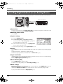
Checking the Included Items
The R-44 comes with the following items. Please check that all of these items are present after opening the
package. If any items are missing, please contact the retailer from whom you purchased the R-44.
■ R-44
■ AC Adaptor
This AC adaptor is designed specifically for the R-44. Do not attempt to use any other adaptor with the R-44.
■ USB Cable (mini B TYPE; 1 meter)
You can use this cable to connect the R-44 to the USB connector of your computer.
* If the AC adaptor or USB cable becomes damaged or if you need a replacement for any reason, please contact one of
the Service Centers listed in the “Information” section at the end of this manual.
* Don't remove the ferrite core that's attached to the USB cable.
■ PRACTICAL GUIDE TO THE EDIROL R-44
This guide describes practical techniques to use with the R-44.
■ Owner’s Manual
This is the document you’re reading. Keep it at hand for ready reference.
8
4AGAPGYDQQMࡍࠫ㧞㧜㧜㧤ᐕ㧡㧝㧡ᣣᦐᧁޓᣣޓඦᓟ㧠ᤨ㧡㧟ಽ
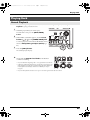
Introducing the R-44
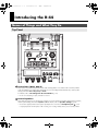
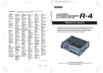
Names of Things and What They Do
Top Panel
fig.panel-1.eps
1
1
3
2
2
4
5
7
8
6
9
10
11
12
17
13
1
14
15
16
Internal Mics [MIC-L, MIC-R]
These stereo mics are built into the R-44. The audio entering MIC-L is recorded on the 1L channel, and the
audio from MIC-R is recorded on the 1R channel. If you are recording with the internal mics, set the System
Settings menu item Recording Setup to Int-Mic.
For details, refer to “Recording from the Internal Mics” (p. 32).
* Do not connect anything to input jacks that are not used.
2
Internal Speakers
These built-in speakers are for monitoring sound. If you want sound to be played from the internal speakers,
set the System Settings menu item Speaker to ON. For details, refer to “Speaker Settings” (p. 44).
* No sounds are played from the internal speakers if headphones are connected to the Headphone jack 25 . Sound
is not played from the internal speakers while recording or in recording-standby mode to prevent acoustic feedback.
9
4AGAPGYDQQMࡍࠫ㧞㧜㧜㧤ᐕ㧡㧝㧡ᣣᦐᧁޓᣣޓඦᓟ㧠ᤨ㧡㧟ಽ
Introducing the R-44
1
1
3
2
2
4
5
7
8
6
9
10
11
12
17
13
3
14
15
16
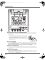
Phantom Power Switches [PHANTOM POWER]
These switches turn the phantom power on/off for the XLR connectors of the combo input jacks located on
the right panel. You can turn phantom power on/off separately for channels 1/2/3/4 because they have
separate switches.
* Always turn the phantom power off when connecting any device other than
condenser microphones that require phantom power. You risk causing damage
if you mistakenly supply phantom power to dynamic microphones, audio
playback devices, or other devices that do not require such power. Be sure to
check the specifications of any microphone you intend to use by referring to the
manual that came with it.
This instrument’s phantom power: 48 V DC, 8 mA Max (total of all channels must be 20 mA or less)
4
Hold Switch [HOLD]
XLR plug
TRS phone
Phone plug
plug
(unbalanced) (balanced)
By selecting the HOLD ON position, you can disable the panel buttons so that unwanted operations will not
occur if a button is pressed accidentally.
However, even if this switch is set to HOLD ON, the Phantom power switches 3 , Low cut switch
5 , Limiter switch 6 , Input level knobs 23 , and Monitor level knob 24 will still be operable.
5
Low Cut Switch [LOW CUT]
Turing this switch on allows you to record while cutting the lower range portion of the input signal. Turn
it on when breath noise (breathing sounds during voice recording) or wind noise (when recording outside)
may be a problem.
6
Limiter Switch [LIMITER]
This switch turns the input level limiter on/off.
The limiter compresses the input level appropriately to prevent distortion when the input level is too high.
The limiter can be set to work with respect to each channel independently or for a combination of channels
(linked). For details, refer to “Limiter link” (p. 68).
10
4AGAPGYDQQMࡍࠫ㧞㧜㧜㧤ᐕ㧡㧝㧡ᣣᦐᧁޓᣣޓඦᓟ㧠ᤨ㧡㧟ಽ
Introducing the R-44
7
Power Switch [POWER]
This switch turns the power on/off. To turn the power on or off, press and hold the [POWER] switch for
about two seconds. The [POWER] switch is lit blue when the power is on.
* Do not turn off power to the R-44 in the following situations. The SD memory card may be damaged.
• When writing to or reading from the SD memory card, such as during recording or playback
If power is mistakenly turned off during recording, the recorded data may not be saved on the SD
memory card.
Note that pressing the power switch during recording will not turn off power.
• When “Now Processing!” or “Checking Card...” appears on the R-44’s display
• When connected to a PC
8
Effects Button [EFFECTS]
This button puts the R-44 in Effect mode, where you can make effect settings. When effects are operating,
the Effect button lights in orange.
For details, refer to “Setting the Color of Sound (Effects Settings)” (p. 55).
9
Exit Button [EXIT]
You use this button to return to the previous screen or to cancel an operation.
10
Scrub Dial [SCRUB/VALUE]
Use this dial to select a setting item or to change a value. You can also turn the scrub dial to move the current
location forward or backward when the R-44 is stopped or when playback is paused.
In the finder screen, the scrub dial can also be used to select songs.
11
Marker Buttons [CLEAR] [
Cursor Buttons [ ] [ ] [
][
] [MARK] /
][ ]
When using as Marker buttons (p. 46)
Clear button [CLEAR]
This button deletes markers assigned with the [MARK] button. Markers are deleted successively,
starting at the marker located immediately before the current location.
Marker button [
]
This button moves the position to the marker immediately before the current location (the previous
marker).
If the current playback location is before the first marker, pressing this button moves the position to the
beginning of the project. The position is also moved to the beginning of the project if no markers have
been set.
Marker button [
]
This button moves the position to the marker immediately following the current location (the next
marker).
If the current playback location is at the last marker, pressing this button moves the position to the end
of the project. The position is also moved to the end of the project if no markers have been set.
Mark button [MARK]
You assign a marker to a desired location in the project file by pressing this button. Markers are
numbered sequentially from the beginning of the project.
When using as Cursor button
You use these buttons to select items shown in the display.
12
MENU Button [MENU]
This button puts the R-44 in different modes where you can make various settings.
For details, refer to “System Setup” (p. 60).
13
A-B Repeat Button [A-B REPEAT]
This button lets you repeatedly play the region between two points (A and B) in the project. Simply assign
marker A and marker B while the project is playing, and playback will repeat between markers A and B.
For details, refer to “Repeat Playback (A-B REPEAT)” (p. 47).
11
4AGAPGYDQQMࡍࠫ㧞㧜㧜㧤ᐕ㧡㧝㧡ᣣᦐᧁޓᣣޓඦᓟ㧠ᤨ㧡㧟ಽ
Introducing the R-44
1
1
3
2
2
4
5
7
8
6
9
10
11
12
17
13
14
14
15
16
PREV Button [PREV]
Pressing the [PREV] button while a project is playing or stopped returns the project to the beginning
(00:00:00:00). Pressing this button at the beginning of a project moves to the previous project.
You can also press and hold down this button to rewind. This feature is available both while playing and
while stopped.
* If Play Mode is set to Single in the Player Setup system setting, you cannot move to the previous or next project
during playback.
15
NEXT Button [NEXT]
Pressing the [NEXT] button jumps to the next project. You can also press and hold this button to fastforward. This feature is available both while playing and while stopped.
* If Play Mode is set to Single in the Player Setup system setting, you cannot move to the previous or next project
during playback.
16
Play Button [PLAY]
This button starts playback. The [PLAY] button is lit blue during playback.
17
Enter/Finder Button [ENTER/FINDER]
You use this button to confirm a setting or to set a value. You can also press this button to use the Finder
function. For more about the Finder function, refer to “Manipulating a Project (Finder)” (p. 48).
12
4AGAPGYDQQMࡍࠫ㧞㧜㧜㧤ᐕ㧡㧝㧡ᣣᦐᧁޓᣣޓඦᓟ㧠ᤨ㧡㧟ಽ
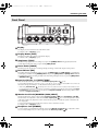
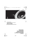
Introducing the R-44
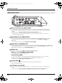
Front Panel
fig.panel-2.eps
18
19
20
23
18
21
24
22
25
Display
The display shows information about the R-44’s status.
For details, refer to “Display” (p. 18).
19
Display Button [DISP]
This button switches the contents of the R-44’s display.
For details, refer to “Display” (p. 18).
20
Stop Button [STOP]
This button stops playback or recording. If you press the [STOP] button during playback, the timer
counter displays the time when you pressed the [STOP] button.
21
Pause Button [PAUSE]
This button pauses playback or recording. During recording, sound is still output even if paused.
22
Record Button [REC]
Recording will begin immediately when you press the [REC] button. The [REC] button is lit red during
recording. If you hold down the [PAUSE] button and press the [REC] button, the [REC] button will blink
red, and the R-44 enters recording standby mode. Recording will begin when you press the [REC] button
or [PAUSE] button 21 .
23
Input Level Knobs 1–4 [LEVEL]/[SENS]
35 (p. 30).
These knobs adjust the input level from each Combo input jack 1–4 34
You can adjust sensitivity to 11 levels: +4, -2, -8, -14, -20, -26, -32, -38, -44, -50, and -56 dBu. You can also set
the level from negative infinity to +8 dB, with the central position at 0 dB.
* When using Internal mics 1 , sensitivity can be set to one of three levels (Low, Mid, or Hi) and the level can
be set from negative infinity to +18 dB. Also, sensitivity for both MIC-L and MIC-R can be adjusted with Input
level knob 1. The level for MIC-L can be adjusted with Input level knob 1, and the level for MIC-R can be
adjusted with Input level knob 2.
24
Monitor Level Knob [MONITOR (PUSH) SELECT]
This knob adjusts the output volume from the Internal speakers
2
and the Headphone jack
25 .
This knob does not adjust the volume from the Line output jacks 33 . If you want to adjust the volume
of the Line output jacks, adjust the controls of the external speakers or playback system connected to the
Line output jacks.
You can press the this knob from the main screen to select a channel to monitor.
For details, refer to “Display” (p. 18).
25
Headphone Jack [PHONES]
You can connect a set of headphones with this jack. Use the Monitor level knob 24 to adjust the volume.
If you connect headphones, no sound is output from the Internal speakers 2 .
13
4AGAPGYDQQMࡍࠫ㧞㧜㧜㧤ᐕ㧡㧝㧡ᣣᦐᧁޓᣣޓඦᓟ㧠ᤨ㧡㧟ಽ
Introducing the R-44
Side Panel (Left)
fig.panel-3.eps
26
30
26
27
28
31
32
29
33
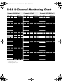
Control Sync Connector [CTRL SYNC]
You can perform clock-synchronized recording of up to 8 channels by connecting two R-44 units with a
mini-type stereo cable via the CTRL SYNC connectors. You can also remotely link recording standby, start,
and stop.
For details, refer to “Remotely Linking Two Connected R-44 Units” (p. 73).
* Remote linking does not guarantee that two R-44 units will start recording at the same time. There will be a
discrepancy of several milliseconds.
27
Digital Output Jack [DIGITAL OUT]
This connector outputs a digital signal. You can connect digital devices, such as speakers or mixers, with a
coaxial type cable. This connector provides the same audio signal as the Headphone jack 25 , but in
digital form.
* The volume cannot be adjusted with the Monitor level knob
28
24
.
Digital Input Jack [DIGITAL IN]
Connect an XLR type cable to this connector to record a digital signal. The digital input signal is recorded in stereo
on channels 1L and 1R. If you want to record in monaural, you must change the Rec Mode setting in the System
Settings menu. For details, refer to “1 Recording Setup” (p. 66).
29
Rubber Flap
Open this cover to expose the Memory card slot and USB connector.
Memory card slot [MEMORY CARD SLOT]
You can insert an SD memory card into this slot.
USB connector [USB]
You can connect the R-44 to your computer with the included USB cable and move or copy recorded
projects. You can also move or copy files from your computer to the SD memory card.
For details, refer to “Connecting to a Computer” (p. 71).
30
Security Slot (
)
You can attach a commercial available security cable to this slot to prevent theft.
http://www.kensington.com/
31
AC Adaptor Jack [DC IN]
You can connect either the included AC adaptor or a commercially available cable for an external power
device.
For details, refer to “Connecting the AC Adaptor and Turning the Power On/Off” (p. 24).
14
4AGAPGYDQQMࡍࠫ㧞㧜㧜㧤ᐕ㧡㧝㧡ᣣᦐᧁޓᣣޓඦᓟ㧠ᤨ㧡㧟ಽ
Introducing the R-44
32
Grounding Terminal
Depending on how the system is setup, you may experience discomfort or perceive that the surface feels
gritty when you touch this device, microphones connected to it, or the metal portions of other objects, such
as guitars. This sensation is caused by an infinitesimal electrical charge, which is absolutely harmless.
However, if you are concerned about this, connect the ground terminal to an external ground. When the
unit is grounded, a slight hum may occur, depending on the setup. If you are unsure of how to connect a
ground, contact the nearest Roland Service Center or an authorized Roland distributor, as listed on the
“Information” page.
Do not connect to these objects
• Water pipes (may result in shock or electrocution)
• Gas pipes (may result in fire or explosion)
• Telephone-line ground or lightning rod (may be dangerous in the event of lightning)
927
33
Line Output Jacks [LINE OUT]
These jacks output an analog audio signal. You can use RCA cables to connect powered speakers, audio
equipment, mixers, and other devices. The regulated output level is fixed at -20 dBu.
* The volume for each channel during playback can be adjusted on the Mixer screen (p. 19).
* Line output can be output as 4-indiv or monitor. Refer to “5 System Setup” in System settings (p. 69) for
details.
15
4AGAPGYDQQMࡍࠫ㧞㧜㧜㧤ᐕ㧡㧝㧡ᣣᦐᧁޓᣣޓඦᓟ㧠ᤨ㧡㧟ಽ
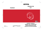
Introducing the R-44
Side Panel (Right)
fig.panel-4.eps
34
34
Combo Input Jacks 1–4
These analog audio input connectors are compatible with mic preamps. They support either XLR or phone
plugs, which can be selected to match the connected device. They also accept either balanced or unbalanced
connections.
You can use Combo input jacks 1–4 as four channels of monaural input or as two stereo pairs, 1/2 and
3/4. For details, refer to “1 Recording Setup” (p. 66).
* The XLR type supports 48 V phantom power and allows you to connect phantom-powered condenser microphones.
In this case, turn on the Phantom power switch 3 on the top panel.
fig.XLR-TRS
922
The R-44 is equipped with balanced (XLR/TRS)
type connectors. The wiring diagrams for these
connectors are shown at right. Connect them
after first checking the wiring diagrams of the
device you intend to connect.
GND(SLEEVE)
1:GND
2:HOT
3:COLD
HOT(TIP)
COLD(RING)
* If connection cables with resistors are used, the volume level of devices connected to the inputs (Combo input jacks
1–4) may be low. If this happens, use connection cables that do not contain resistors.
* To disconnect an XLR-type cable, push the metal latch while you unplug the connector.
16
4AGAPGYDQQMࡍࠫ㧞㧜㧜㧤ᐕ㧡㧝㧡ᣣᦐᧁޓᣣޓඦᓟ㧠ᤨ㧡㧟ಽ
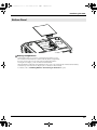
Introducing the R-44
Bottom Panel
fig.panel-5.eps
35
35
Battery Compartment
Install batteries here if you want to operate the R-44 on battery power.
The orientation of the batteries is shown inside the battery compartment.
Be sure to observe the correct polarity when installing the batteries.
If using the AC adaptor, you do not need to install batteries.
When the R-44 has sufficiently charged batteries, the power source automatically switches between battery
and external power when the AC adaptor jack is connected or disconnected.
For details, refer to “Installing Batteries and Turning on the Power” (p. 25).
17
4AGAPGYDQQMࡍࠫ㧞㧜㧜㧤ᐕ㧡㧝㧡ᣣᦐᧁޓᣣޓඦᓟ㧠ᤨ㧡㧟ಽ
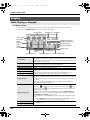
Introducing the R-44
Display
While Playing or Stopped
The Main screen
The R-44’s Main screen displays information about the project and the operational status of the R-44.
You can press the [DISP] button to change the contents of the display.
fig.play-disp.eps
Project name
Progress bar
Total time
Time counter
Level scale
dBFS
Sampling frequency
Sample size (bit depth)
̄
Channel
names
Marker indicators
Clip level indicators
Output
assignments
Power source
Channel level
meters
Status indication
Project name
Time counter
Progress bar
Total time (LEN: Length)
Level scale dBFS
Clip level indicators
Channel level meters
Channel names
Clip level indicators
Sampling frequency
Sample size (bit depth)
18
Monitor level meters
Displays the name of the project. The file name is shown when you copy WAV
files from your computer via USB to the R-44’s SD memory card. File names
containing double-byte characters (e.g., Japanese) are not displayed correctly,
but such files can be played.
Displays the time elapsed from the beginning of the project to the current
position in hour:minute:second:1/100 second format.
Displays the current playback location relative to the entire project.
Displays the total time of the entire project.
Displays the sound level for each channel (after adjusting input levels) in real
time.
The markings are relative to 0 dBFS (Full Scale) of the digital signal. For
example, 12 indicates -12 dBFS. C is the clipping level (0 dBFS).
Displays up to four channel names. When using one stereo channel, 1L and
1R are shown. When using two stereo channels, 1L, 1R, 2L, and 2R are shown.
For monaural projects, 1, 2, 3, and/or 4 is shown according to the number of
channels.
When the sensitivity setting is too high and clipping occurs the display is
shown in inverted black and white.
Displays how the audio of each channel is assigned to the L/R output
channels.
Output assignments
Date and time
means that the audio is output to the left channel,
to the
right channel, and
to both left and right channels. Channels that are not
shown are not output.
You can select a channel to be monitored by pressing the Monitor Level
knob. You can also restore the default settings by pressing and holding down
the Monitor Level knob for one second.
The output is sent to the PHONES jack, Line output jacks, and digital output
jack.
* When Output Sel (p. 69) in the system settings is set to “monitor,” the Line
output jacks output sound as set in the output assignments.
Displays the sampling frequency and sample size (bit depth) of the currently
selected project.
4AGAPGYDQQMࡍࠫ㧞㧜㧜㧤ᐕ㧡㧝㧡ᣣᦐᧁޓᣣޓඦᓟ㧠ᤨ㧡㧟ಽ
Introducing the R-44
Marker indicator
Monitor level meters
Clip level indicators
Power source
Date and time
The number on the left is the number of the marker located immediately
before the current time counter value. The number on the right indicates the
total number of markers assigned in the currently selected project.
E indicates the end of the current project.
These are the output level meters. The output level assigned to the L/R
channels of the monitor is displayed as the final output level after mixing the
L and R channels separately. You can adjust the level of each channel with the
channel level sliders from the Mixer screen. The level meter is calibrated at
-36, -20, -12, -6, or -3 dBFS from the left.
Displays the power supply source for the R-44. When power is supplied via
the AC adaptor, a power plug icon is shown; when power is supplied via
batteries or an external power supply device (p. 27), a battery icon is
displayed.
Displays the current date and time (p. 62, p. 70).
If you press the [DISP] button from the Main screen, the progress bar area changes so the remaining
project time (REM: REMAIN) is shown.
fig.play-disp2.eps
Remaining time
Remaining time
Displays the remaining time during playback from the current location to the
end of the project.
The Mixer screen
From the Main screen, press the [DISP] button twice to show the Mixer screen.
This screen lets you adjust the volume balance for monitoring.
fig.play-disp3.eps
Channel names
Channel level
sliders
Output assignments
Channel level meters
Monitor level meters
Channel level sliders
These sliders adjust the playback level for each channel. Use the CURSOR
buttons [ ] [ ] to select a slider, and turn the [SCRUB/VALUE] dial to
adjust the value. Each slider can be adjusted within the range 0–120. The
default value is 100.
* The settings are stored by the R-44 and not in the project. When you turn off
the power, the settings revert to the default value.
* These settings do not affect the recording levels.
19
4AGAPGYDQQMࡍࠫ㧞㧜㧜㧤ᐕ㧡㧝㧡ᣣᦐᧁޓᣣޓඦᓟ㧠ᤨ㧡㧟ಽ
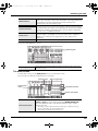
Introducing the R-44
While Recording or in Recording Standby
The Main screen
The R-44’s Main screen displays information about the project and the operational status of the R-44.
You can press the [DISP] button to change the contents of the display.
Time counter
Time counter
Recordable time
Total recording time
Recordable time
Total recording time
Displays the time elapsed from the beginning of the project to the current
position in hour:minute:second:1/100 second format.
Displays the time that recording can take place.
Displays the total time from the beginning of recording to the current location.
* Even if you record continuously, another new project will be created
automatically when the project reaches 2 GB in size, and recording will
continue. Even for recordings spanning multiple projects, the elapsed time
since you first pressed the [REC] button is shown here.
* For an explanation of the other displays, refer to “While Playing or Stopped” (p. 18).
If you press the [DISP] button from the Main screen, the recordable time display area shows the remaining
space on the SD memory card.
Remaining space on
SD memory card.
Remaining space on SD
memory card
20
Displays the amount of free space on the SD memory card.
4AGAPGYDQQMࡍࠫ㧞㧜㧜㧤ᐕ㧡㧝㧡ᣣᦐᧁޓᣣޓඦᓟ㧠ᤨ㧡㧟ಽ
Introducing the R-44
From the Main screen, press the [DISP] button twice to show the recording buffer capacity (BUF: buffer
gauge).
Remaining buffer space
The recording buffer is memory that temporarily stores the input sound before it is written to the SD
memory card. The buffer gauge indicates how much of the recording buffer has been used. Normally, the
recording buffer never reaches capacity because input sound is immediately written to the SD memory
card. However, if the SD memory card processing capability decreases and writing data to the SD memory
card is delayed, then the data may accumulate to an excess and the buffer may overflow. (The SD memory
card processing capability may be affected if file arrangement on the card becomes irregular due to project
files being repeatedly written and deleted. If such a situation is encountered, you can restore the card to its
original processing capability by formatting it.)
* When the recording buffer is close to capacity, the “SD buffering” message is displayed.
* When the recording buffer reaches capacity, the buffer gauge moves all the way to the right edge and the “SD Card
Slow!” message is shown. Recording does not stop even if the “SD Slow” message is displayed, but some sound is
not recorded. This message will not disappear until a button is pressed.
* For important recordings, we recommend formatting the SD memory card before use.
* Some SD memory cards may have a slow writing speed, so that even immediately after they have been formatted,
recording at a high bit rate may cause a similar message to be displayed. When purchasing an SD memory card,
please check whether it has been verified to work correctly with the R-44 (p. 76).
21
4AGAPGYDQQMࡍࠫ㧞㧜㧜㧤ᐕ㧡㧝㧡ᣣᦐᧁޓᣣޓඦᓟ㧠ᤨ㧡㧟ಽ
Introducing the R-44
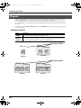
Projects
On the R-44, the data that you record and play back are handled in units called projects. On the SD memory
card, each project actually consists of a folder with one or more files, as shown below.
If you connect the R-44 to your computer, you can see how these folders and files are organized. However,
if you change, delete, or rename the files within a project, the R-44 may be unable to play that project. Please
use caution.
In the system settings, the Recording Setup parameter Rec Mode (p. 67) lets you specify the type of project
you want to record.
Monaural projects
Type
Structure
If there is only one channel, a monaural WAV file will be created with a name
consisting of the project name and a .wav extension.
If there are 2–4 channels, a folder will be created with a name consisting of the project
name plus an extension of .pjt. In that folder, monaural WAV files will be created with
names consisting of the channel number and a .wav extension.
MONOx1
MONOx2
MONOx3
MONOx4
fig.project-M1.eps
Project Name
ABC-1.wav
ABC-2.pjt
1.wav
ABC-1
.wav
(MONO)
(MONO)
2.wav
(MONO)
MONOx2
MONOx1
Project Name
ABC-3.pjt
1.wav
(MONO)
2.wav
(MONO)
MONOx3
22
ABC-4.pjt
3.wav
(MONO)
1.wav
2.wav
3.wav
4.wav
(MONO) (MONO) (MONO) (MONO)
MONOx4
4AGAPGYDQQMࡍࠫ㧞㧜㧜㧤ᐕ㧡㧝㧡ᣣᦐᧁޓᣣޓඦᓟ㧠ᤨ㧡㧟ಽ
Introducing the R-44
Stereo projects
Type
STEREOx1
STEREOx2
Structure
If there is only one stereo channel pair, a stereo WAV file will be created with a name
consisting of the project name and a .wav extension.
If there are two stereo channel pairs, a folder will be created with a name consisting of
the project name plus an extension of .pjt. In that folder, stereo WAV files will be
created with names consisting of the channel number and a .wav extension.
fig.project-S1.eps
Project Name
ABC-2.pjt
ABC-6.pjt
ABC-5.wav
ABC-5
.wav
1.wav
(STEREO)
(STEREO)
STEREOx1
2.wav
(STEREO)
STEREOx2
Four-channel projects
Type
4CH
ABC-7.wav
Structure
A four-channel WAV file will be created with a name consisting of the project name
and a .wav extension.
Project Name
ABC-7.
wav
(4CH)
* If you want to load these files onto your computer, make sure
that your waveform editing software supports four-channel
files.
4CH
Limitations on file size
The R-44 can handle files up to 2 GB in size. If the file size reaches 2 GB during recording, the file is closed.
Then, a new file is created and recording continues. When you finish recording, these files appear as
separate projects.
About BWF
In “5 System Setup” (p. 69), under system settings, you can set Project File to BWF so that the files
created during recording and editing will be BWF files. BWF (Broadcast Wave Format) files contain
information about the recording time and recording device (EDIROL R-44) in addition to the data of a
conventional WAV file. The file can be used by waveform editing software that supports BWF.
Caution when copying files from your computer
Be aware of the following when copying files from your computer to the R-44’s SD memory card.
• The R-44 can play only linear PCM WAV files at sampling frequencies of 44.1, 48, 88.2, 96, or 192 kHz and
bit depths of 16 or 24 bits. It cannot play any other type of file.
• File and folder names containing double-byte characters (e.g., Japanese) are not displayed correctly.
• Any files other than WAV files cannot be recognized by the R-44 and will not be displayed.
• Files beginning with “.” (dot) will not be displayed.
• You must not copy files larger than 2 GB into the R-44’s SD memory card. Doing so will make the R-44’s
operation unstable, and in the worst case might even damage the files in the SD memory card.
23
4AGAPGYDQQMࡍࠫ㧞㧜㧜㧤ᐕ㧡㧝㧡ᣣᦐᧁޓᣣޓඦᓟ㧠ᤨ㧡㧟ಽ
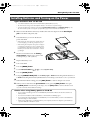
Getting Ready to Use the R-44
Connecting the AC Adaptor and Turning the Power On/Off
* Once the connections have been completed, turn on power to your various devices in the order specified. By turning
on devices in the wrong order, you risk causing malfunction and/or damage to speakers and other devices.
* Reduce the volume before turning on power. Even when the volume is turned down, sound may be produced when
turning on the power. This is not a defect.
* If you connect the AC adaptor when batteries are installed, the power will be supplied from the AC adaptor.
932
* Place the AC adaptor so the side with the indicator (refer to illustration) faces upwards and the side with textual
information faces downwards. The indicator will light when you plug the AC adaptor into an AC outlet.
Indicator
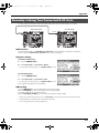
Turning on the power
1
Insert the AC adaptor into the AC adaptor jack on the R-44’s side panel (left).
* Use only the included AC adaptor.
2
Plug the AC adaptor into an AC power outlet.
3 To turn the power on, press and hold the [POWER] switch for about two seconds.
Wait until the Main screen appears.
942
* Due to a circuitry protection feature, this unit requires a few moments after power-up before it is ready for normal
operation.
Turning off the power
1 Confirm that recording/playback has been stopped.
2
*923
24
While the Main screen is displayed, press and hold the [POWER] switch for about 2 seconds to turn
the power off.
* If there are batteries in the unit while an AC adaptor is being used, normal operation will continue should the line
voltage be interrupted (power blackout or power cord disconnection).
4AGAPGYDQQMࡍࠫ㧞㧜㧜㧤ᐕ㧡㧝㧡ᣣᦐᧁޓᣣޓඦᓟ㧠ᤨ㧡㧟ಽ
Getting Ready to Use the R-44
Installing Batteries and Turning on the Power
Types of batteries that can be used
• AA alkaline batteries (LR6) and AA nickel metal-hydride (HR15/51) only
* The R-44 cannot recharge nickel metal-hydride batteries. You must use a separate charger.
* You must specify the type of batteries in the R-44’s System Settings menu item “5 System Setup” (p. 69).
The R-44 will not operate correctly if the specified battery type does not match the actual batteries.
1
Make sure that the R-44 is turned off, and disconnect the AC adaptor from the AC adaptor
jack on the R-44’s side panel (left).
fig.battely.eps
2
Detach the battery cover from the bottom
panel of the R-44.
* When turning the unit upside-down, handle with care
to avoid dropping it, or allowing it to fall or tip over.
* When turning the unit upside-down, place newspapers
or magazines under the four corners or at both ends to
prevent damage to the buttons and controls. Also, you
should try to orient the unit so no buttons or controls
get damaged.
3
4
5
Insert four AA batteries into the battery
compartment, making sure to observe the
correct polarity (+ and - symbols).
Replace the battery cover.
Turn on the R-44.
6 Press the [MENU] button.
7
8
Use the Cursor buttons [
][
] to select 5 System Setup.
Press the [ENTER] button.
9 Using the [SCRUB/VALUE] dial, set the Battery Type to Alkaline if installing alkaline batteries or
to Ni-MH if installing nickel metal-hydride batteries. The setting is activated as soon as you select it.
10
When finished with the setting, press the [EXIT] button to return to the previous screen.
11 When you have returned to the System Menu screen, press the [EXIT] button once again.
The [ENTER] button will be blinking on the display. Press the [EXIT] button to return to the Main screen
if you do not need to make additional settings.
Caution when using battery power on the R-44
• If you operate on battery power for an extended time, the batteries will become hot. Be careful not to
burn yourself.
• Do not mix new batteries with used batteries or mix batteries of differing types.
• If you will not be using the R-44 for an extended time, we recommend that you remove the batteries to
prevent leakage or other accidents.
• When using a USB cable to connect the R-44 to your computer, use the AC adaptor to prevent the loss
of power while the connection is active.
25
4AGAPGYDQQMࡍࠫ㧞㧜㧜㧤ᐕ㧡㧝㧡ᣣᦐᧁޓᣣޓඦᓟ㧠ᤨ㧡㧟ಽ
Getting Ready to Use the R-44
Battery Status
When using the R-44 on battery power, a battery icon is shown in the lower right of the display. As battery
capacity decreases, the battery icon changes as follows.
Remaining charge
Display
Level 4 (sufficient)
Level 3
Level 2
Level 1
Level 0 (little remaining)
fig.bat-caution.eps
When the battery reaches Level 0, the message in the figure is
shown. Replace the batteries as soon as possible.
If you continue using the R-44 when the batteries are low, the
screen is the figure is shown, and then the power automatically
turns off shortly thereafter.
Battery life
961
(When using alkaline batteries, 44.1 kHz, 16-bit, stereo, with phantom power off)
Continuous playback
Continuous recording
approximately 4 hours
approximately 4 hours
* The values for battery life shown above are only approximate; they will vary depending on your system and
conditions of use.
* Battery life is shorter when the following settings are used.
Illumination is on, button lights are bright, display is bright, phantom power is on, sampling frequency is high, 4channel recording is used, or the internal speakers are used.
26
4AGAPGYDQQMࡍࠫ㧞㧜㧜㧤ᐕ㧡㧝㧡ᣣᦐᧁޓᣣޓඦᓟ㧠ᤨ㧡㧟ಽ
Getting Ready to Use the R-44
Using External Power Sources
When using an external power supply, be sure to set the final voltage.
The final voltage refers to the voltage when voltage can no longer be supplied because the capacity of the
external power source is reduced and voltage decreases as electricity is consumed. If the final voltage is not
properly set for the external power source, the remaining power display cannot be shown. Refer to the
user’s manual of the external power supply for the final voltage value.
Furthermore, when the “Battery Low” message is displayed, the recording automatically stops, and the
power automatically turns off. Turn the R-44’s power off and change the external power source.
* When using an external power source, even when power is automatically cut off, the R-44 starts within 30 seconds
after power is turned back on. During this period, the final voltage settings can be changed.
* Read the following to set the final voltage for the R-44.
Refer to the user’s manual for the external power source when using an external power source.
Setting the final voltage
ion.eps
1
Press the [MENU] button.
The display shows the System menu.
ion.eps
2
Use the Cursor buttons [ ] [ ] to select 5 System Set
Up, and press the [ENTER] button.
The System Setup screen is shown.
ion.eps
3
Use the Cursor buttons [
][
] to select the Ext-
Power item.
ion.eps
4
Use the [SCRUB/VALUE] dial to set the final voltage.
Final voltage values:
Adaptor/9.0/9.5/10.0/10.5/11.0/11.5/12.0 V
* The final voltage value will differ according to the external power
source specifications. Check the specifications for the external power
source being used for details.
* When the AC adaptor is used for power, set the final voltage (ExtPower) to Adaptor.
5
Press the [EXIT] button twice to return to the Main screen.
This completes setting the final voltage.
27
4AGAPGYDQQMࡍࠫ㧞㧜㧜㧤ᐕ㧡㧝㧡ᣣᦐᧁޓᣣޓඦᓟ㧠ᤨ㧡㧟ಽ
Getting Ready to Use the R-44
Preparing the SD Memory Card
The R-44 uses an SD memory card.
The SD memory card is sold separately. Visit the Roland website (http://www.roland.com) before making
a purchase. The website provides the most recent information regarding compatibility.
Inserting the SD Memory Card
1
Confirm that the power is turned off.
If the power is on, turn it off. Press and hold the [POWER] switch on the R-44 to turn power on or off.
2
3
931
Open the Rubber flap on the side
of the unit.
Insert the memory card.
* When inserting the SD memory card, make
sure the front of the card is facing up and
insert the card slowly. If the card is forcibly
inserted incorrectly, the R-44 or the SD
memory card may be damaged. Please
exercise caution.
Rubber flap
SD memory card
* Carefully insert the memory card all the way in until it is firmly in place.
4
Close the Rubber flap.
5 Turn power on.
Press and hold down the [POWER] switch to turn on the power.
When using an SD memory card with the R-44 for the first time
When using an SD memory card with the R-44 for the first time, the memory card must be formatted.
Please format the memory card following the procedure in “Formatting and Checking the SD Memory
Card” (p. 64). “SD Unformatted” is shown when an unformatted memory card is inserted into the R-44.
The SD memory card write protect feature (LOCK)
Write protect switch
The contents of the memory card can be protected by sliding the write protect switch
on the side of the memory card to the “LOCK” position. Unlock the write protect
switch to delete data on the card.
Removing the SD Memory Card
1 Turn off power to the R-44.
2
3
Open the Rubber flap.
Lightly push the memory card inward, then release it.
Remove the memory card after it pops out toward you.
* Never insert or remove a memory card while this unit's power is on. Doing so may corrupt the data on the memory card.
28
4AGAPGYDQQMࡍࠫ㧞㧜㧜㧤ᐕ㧡㧝㧡ᣣᦐᧁޓᣣޓඦᓟ㧠ᤨ㧡㧟ಽ
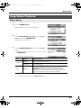
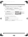
Recording
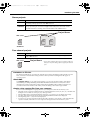
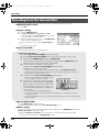
Recording from a Connected Microphone
The following describes how to record audio from a maximum of four microphones connected to the R-44’s
Combo input jacks.
fig.mic-1.eps
Turn this ON
if you’re using a
condenser microphone.
Microphone(s)
Adjust the input
LEVEL and SENS
● Connections
983
Connect the microphone(s) to the Combo input jack(s).
Acoustic feedback could be produced depending on the location of microphones relative to speakers. This
can be remedied by:
1. Changing the orientation of the microphone(s).
2. Relocating microphone(s) at a greater distance from speakers.
3. Lowering volume levels.
● Phantom power switch
Turn this ON when connecting a phantom-powered condenser microphones.
fig.input-analog.eps
● System settings
1. Press the [MENU] button.
2. In 1 Recording Setup, set Input Select to Analog.
Set the other items in 1 Recording Setup as appropriate
for the recording you want to make.
3. When finished with the settings, press the [EXIT] button
twice to return to the Main screen.
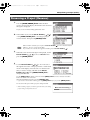
* For more about system settings, refer to “System Setup” (p. 60).
● Limiter
Turn this ON if you want to prevent unexpectedly loud sounds or strong attacks from producing clipping noise.
The limiter threshold is -10 dB relative to digital full scale.
The limiter can group and link each channel. Refer to Limiter link (p. 68).
29
4AGAPGYDQQMࡍࠫ㧞㧜㧜㧤ᐕ㧡㧝㧡ᣣᦐᧁޓᣣޓඦᓟ㧠ᤨ㧡㧟ಽ
Recording
● Low cut
You can turn low cut ON when breathing noise (the sound of breathing while recording a voice) or wind
noise (when recording outside) may be a problem.
The low cut feature records while cutting the lower range of the input signal.
● Input level knobs
These knobs adjust sensitivity/input levels.
When recording in STEREOx2, these knobs control the following signals.
Channel 1
Channel 2
Channel 3
Channel 4
STEREO 1 L-channel
STEREO 1 R-channel
STEREO 2 L-channel
STEREO 2 R-channel
SENS/INPUT LEVEL 1 knob
SENS/INPUT LEVEL 2 knob
SENS/INPUT LEVEL 3 knob
SENS/INPUT LEVEL 4 knob
Adjusting the input levels
1. Turn the Input level knob [SENS] (outer) all the way left.
2. Turn the Input level knob [LEVEL] (inner) to the center position. This position is 0 dB.
3. Hold down the [PAUSE] button and press the [REC] button.
The R-44 enters recording standby mode. During recording standby, the [REC] button blinks
and the indication alternates between REC and STANDBY.
4. Play the sound to be recorded into the microphone.
Gradually turn the Input level knob [SENS] toward the right.
Sensitivity has 11 steps of +4, -2, -8, -14, -20, -26, -32, -38, -44, -50, and -56 dBu.
* When the channel name display reverses, the input level has reached the clipping level. Set the knob
to the position just before the display reverses.
5. Adjust the Input level knob [LEVEL] so that the Level
meter shown in the display reaches a point slightly
before C (clip level). If the recording level is too low,
quiet sounds will not be recorded. If the recording level
is too high, loud sounds will be distorted, producing a
crackling noise in the recording.
* When the channel name is blinking, clipping has occurred at
the sensitivity adjustment stage. In this case, clipping
occurs even if the Level meter does not reach the clip level.
level meter (dBFS)
* The Level meter displays the clip level (C) in values relative to 0 dBFS (FS = full scale).
For example, 12 indicates -12 dBFS.
Difference between sensitivity and input level
Sensitivity and input level are differentiated in their use, as shown below.
Sensitivity
Input Level
Adjusts to an appropriate volume according to the input signal strength.
Adjusts the volume balance between the channels.
Also, performs minute adjustments when adjusting cannot be done with sensitivity.
Noise can be controlled by adjusting sensitivity to the largest value without distortion.
30
4AGAPGYDQQMࡍࠫ㧞㧜㧜㧤ᐕ㧡㧝㧡ᣣᦐᧁޓᣣޓඦᓟ㧠ᤨ㧡㧟ಽ
Recording
● Record button [REC]
If you want to begin recording immediately, press the [REC] button.
Recording standby
If you want to put the R-44 in recording standby
mode to be ready to record, hold down the
[PAUSE] button and press the [REC] button.
Recording-standby
During recording standby, the [REC] button blinks and the
indication alternates between REC and STANDBY.
When recording is paused, the [REC] button blinks. In
addition, the indication alternates between REC and
PAUSE.
Press the [REC] or [PAUSE] button during recording
standby or while paused to start recording.
You can adjust input levels during recording standby.
● Other settings
If you want to monitor the sound being recorded, connect headphones to the PHONES jack and use the
Monitor level knob to adjust the volume.
Adjusting the Monitor level knob does not affect the level of the sound actually being recorded.
To play the recorded sound, refer to “Playing Back” (p. 41).
31
4AGAPGYDQQMࡍࠫ㧞㧜㧜㧤ᐕ㧡㧝㧡ᣣᦐᧁޓᣣޓඦᓟ㧠ᤨ㧡㧟ಽ
Recording
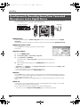
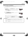
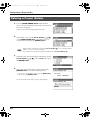
Recording from the Internal Mics
The following describes how to record an audio source via the R-44’s internal microphones.
● Phantom power switch
Turn this OFF.
.input-intmic.eps
● System settings
1. Press the [MENU] button.
2. In 1 Recording Setup, set Input Select to IntMic.
Set the other items in 1 Recording Setup as appropriate
for the recording you want to make.
3. When finished with the settings, press the [EXIT] button
twice to return to the Main screen.
* For more about system settings, refer to “System Setup” (p.
60).
* The limiter settings are invalid.
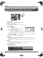
● Input level knobs
These knobs adjust the sensitivity and input levels.
Adjusting the input levels
1. Turn the Input level knob [SENS] (outer) all the way left.
2. Turn the Input level knobs [LEVEL] (inner) to the center position. This position is 0 dB.
3. Hold down the [PAUSE] button and press the [REC] button.
The R-44 enters recording standby mode. During recording standby, the [REC] button blinks
and the indication alternates between REC and STANDBY.
4. Play the sound to be recorded into the microphone.
Gradually turn the Input level knob [SENS] 1 toward the right.
Sensitivity has 3 steps: Lo, Mid, and Hi.
* Sensitivity can be changed simultaneously for both MIC-L and -R with Input Level knob 1.
* When the channel name display reverses, the input level has reached the clipping level. Set the knob
to the position just before the display reverses.
5. Gradually turn the Input level knob [LEVEL] toward the right.
* Input levels of the internal mics are adjusted by Input
level knob 1 (MIC-L) and knob 2 (MIC-R).
6. Adjust the level so that the level meter shown in the
display reaches a point slightly before C (clip level).
If the recording level is too low, quiet sounds will not
be recorded. If the recording level is too high, loud
sounds will be distorted, producing a crackling noise
in the recording.
level meter (dBFS)
* When the channel name is blinking, clipping has
occurred at the sensitivity adjustment stage. In this case, clipping occurs even if the level meter does
not reach the clip level.
* The level meter displays the clip level (C) in values relative to 0 dBFS (FS = full scale). For example, 12
indicates -12 dBFS.
● Record button [REC]
Press the [REC] button to begin recording.
For details on recording standby, refer to “Recording standby” (p. 31).
● Other settings
If you want to monitor the sound being recorded, connect headphones to the PHONES jack and use the
Monitor level knob to adjust the volume.
Adjusting the Monitor level knob does not affect the level of the sound actually being recorded.
To play the recorded sound, refer to “Playing Back” (p. 41).
32
4AGAPGYDQQMࡍࠫ㧞㧜㧜㧤ᐕ㧡㧝㧡ᣣᦐᧁޓᣣޓඦᓟ㧠ᤨ㧡㧟ಽ
Recording
Recording Digital Audio from a Digital Device
The following describes how to record from a digital device connected to the R-44’s Digital input jack.
fig.digital.eps
CD player for playback
DIGITAL IN
DIGITAL OUT
● Connections
Connect your digital device to the Digital input jack. You will need a separately available coaxial cable
to connect your device to the R-44’s Digital input jack.
● Phantom power switch
Turn this OFF.
fig.input-digital.eps
● System settings
1. Press the [MENU] button.
2. In 1 Recording Setup, set Input Select to Digital.
3. Set the sampling frequency to match the input source.
4. Set the other items in 1 Recording Setup as appropriate
for the recording you want to make.
5. When finished with the settings, press the [EXIT] button twice to return to the Main screen.
* For more about system settings, refer to “System Setup” (p. 60).
* Please set the sampling frequency to match the device being input.
* The R-44 is able to synchronize to the clock signal of the Digital input jack.
* When the input sampling frequency and set sample size differ, the sampling frequency display blinks and mute data
is generated.
* When Sync Mode is set to Slave, digital input is disabled. Set Sync Mode to Master when recording from a digital
device. Refer to “5 System Setup” (p. 69) in “System Setup” for settings.
● Record button [REC]
Press the [REC] button to begin recording.
For details on recording standby, refer to “Recording standby” (p. 31).
● Other settings
If you want to monitor the sound being recorded, connect headphones to the PHONES jack and use the
Monitor level knob to adjust the volume.
Adjusting the Monitor level knob does not affect the level of the sound actually being recorded.
To play the recorded sound, refer to “Playing Back” (p. 41).
33
4AGAPGYDQQMࡍࠫ㧞㧜㧜㧤ᐕ㧡㧝㧡ᣣᦐᧁޓᣣޓඦᓟ㧠ᤨ㧡㧟ಽ
Recording
Simultaneously Recording Sound from Connected
Microphones and a Digital Device
The following describes how to record sound from microphones connected to the R-44’s Combo input jacks
3 and 4 and a digital device connected to the Digital input jack.
CD player for playback
DIGITAL IN
Microphones
DIGITAL OUT
● Connections
Connect your microphones to Combo input jacks 3 and 4. Connect your digital device to the Digital
input jack.
You will need a separately available coaxial cable to connect your device to the R-44’s Digital input jack.
● Phantom power switch
Turn this ON when connecting a phantom-powered condenser
microphones.
● System settings
1. Press the [MENU] button.
2. In 1 Recording Setup, set Input Select to Dig+Ana.
3. Set the Rec Mode to STEREOx2.
Set the other items in 1 Recording Setup as appropriate for the recording you
want to make.
4. When finished with the settings, press the [EXIT] button twice to return to the
Main screen.
* If Rec Freq is set to 192 kHz after setting Dig+Ana, Input Select is automatically changed to Digital and Rec
Mode is changed to STEREOx1.
* Please set the sampling frequency to match the device being input.
* For more about system settings, refer to “System Setup” (p. 60).
● Limiter
Turn this OFF when recording an audio source whose levels have already been adjusted (in contrast to a
live audio source whose levels might change unpredictably), or if you have already checked the maximum
volume levels that are going to occur.
Turn this ON if you need to prevent clipping (distortion) caused by unexpected loud volumes or strong
attacks.
● Low cut
You can turn low cut on when breathing noise (the sound of breathing while recording a voice) or wind
noise (when recording outside) may be a problem.
The low cut feature records while cutting the lower range of the input signal.
* The Limiter, Low cut and Input level knob [SENS] settings are invalid for digital input.
34
4AGAPGYDQQMࡍࠫ㧞㧜㧜㧤ᐕ㧡㧝㧡ᣣᦐᧁޓᣣޓඦᓟ㧠ᤨ㧡㧟ಽ
Recording
● Input level knobs
These knobs adjust the input levels.
Use the following when simultaneously recording sound from microphones and a digital device.
Channel 1
Channel 2
Channel 3
Channel 4
Digital input L channel
Digital input R channel
Analog input L channel
Analog input R channel
The input level and sensitivity cannot be
adjusted with the input level knob.
Input level, SENS knob 3
Input level, SENS knob 4
Refer to “Adjusting the input levels” (p. 30).
● Record button [REC]
Press the [REC] button to begin recording.
For details on recording standby, refer to “Recording standby” (p. 31).
● Other settings
If you want to monitor the sound being recorded, connect headphones to the PHONES jack and use the
Monitor level knob to adjust the volume.
Adjusting the Monitor level knob does not affect the level of the sound actually being recorded.
To play the recorded sound, refer to “Playing Back” (p. 41).
35
4AGAPGYDQQMࡍࠫ㧞㧜㧜㧤ᐕ㧡㧝㧡ᣣᦐᧁޓᣣޓඦᓟ㧠ᤨ㧡㧟ಽ
Recording
Simultaneously Recording Sound from Connected
External Microphones and the Internal Mics
The following describes how to record sound from the microphones connected to the R-44’s Combo input
jacks 3 and 4 and the internal mics.
Microphones
● Connections
Connect your microphones to Combo input jacks 3 and 4.
● Phantom power switch
Turn this ON when connecting phantom-powered condenser microphones.
fig.input-analog.eps
● System settings
1. Press the [MENU] button.
2. In 1 Recording Setup, set Input Select to Int+Ana.
3. Set the Rec Mode to STEREOx2.
Set the other items in 1 Recording Setup as appropriate
for the recording you want to make.
4. When finished with the settings, press the [EXIT] button
twice to return to the Main screen.
* If Rec Freq is set to 192 kHz after setting Int+Ana, Input Select is automatically changed to Digital and Rec
Mode is changed to STEREOx1.
* For more about system settings, refer to “System Setup” (p. 60).
● Limiter
Turn this OFF when recording an audio source whose levels have already been adjusted (in contrast to a
live audio source whose levels might change unpredictably), or if you have already checked the maximum
volume levels that are going to occur.
Turn this ON if you need to prevent clipping (distortion) caused by unexpected loud volumes or strong
attacks.
● Low cut
You can turn low cut on when breathing noise (the sound of breathing while recording a voice) or wind
noise (when recording outside) may be a problem.
The low cut feature records while cutting the lower range of the input signal.
● Input level knobs
These knobs adjust input levels.
Use the following when simultaneously recording sound from internal and external microphones.
Channel 1
Channel 2
Channel 3
Channel 4
Internal mic L channel
Internal mic R channel
Analog input L channel
Analog input R channel
Refer to Adjusting the input levels (p. 30).
36
Input level, SENS knob 1
Input level, SENS knob 3
Input level, SENS knob 4
4AGAPGYDQQMࡍࠫ㧞㧜㧜㧤ᐕ㧡㧝㧡ᣣᦐᧁޓᣣޓඦᓟ㧠ᤨ㧡㧟ಽ
Recording
● Record button [REC]
Press the [REC] button to begin recording.
For details on recording standby, refer to “Recording standby” (p. 31).
● Other settings
If you want to monitor the sound being recorded, connect headphones to the PHONES jack and use the
Monitor level knob to adjust the volume.
Adjusting the Monitor level knob does not affect the level of the sound actually being recorded.
To play the recorded sound, refer to “Playing Back” (p. 41).
37
4AGAPGYDQQMࡍࠫ㧞㧜㧜㧤ᐕ㧡㧝㧡ᣣᦐᧁޓᣣޓඦᓟ㧠ᤨ㧡㧟ಽ
Recording
Recording Digital Audio from an Analog Device
The following describes how to record from an analog device connected to the R-44’s Combo input jacks.
fig.digital.eps
CD player for playback
● Connections
Connect your analog device to the Combo input jacks. You will need a separately available audio cable
to connect your device to the R-44’s Combo input jacks.
● Phantom power switch
Turn this OFF.
fig.input-digital.eps
● System settings
1. Press the [MENU] button.
2. In 1 Recording Setup, set Input Select to Analog.
Set the other items in 1 Recording Setup as appropriate
for the recording you want to make.
3. When finished with the settings, press the [EXIT] button
twice to return to the Main screen.
* For more about system settings, refer to “System Setup” (p. 60).
● Limiter
Turn this ON if you want to prevent unexpectedly loud sounds or strong attacks from producing clipping
noise.
The limiter threshold is -10 dB relative to digital full scale.
The limiter can group and link each channel. Refer to “Limiter link” (p. 68).
● Input level knobs
Adjust the Input level 1 (L) and 2 (R) knobs. If there are channels to which you have not connected anything,
turn their Input level knobs to the minimum position.
Refer to “Adjusting the input levels” (p. 30).
● Record button [REC]
Press the [REC] button to begin recording.
For details on recording standby, refer to “Recording standby” (p. 31).
● Other settings
If you want to monitor the sound being recorded, connect headphones to the PHONES jack and use the
Monitor level knob to adjust the volume.
Adjusting the Monitor level knob does not affect the level of the sound actually being recorded.
To play the recorded sound, refer to “Playing Back” (p. 41).
38
4AGAPGYDQQMࡍࠫ㧞㧜㧜㧤ᐕ㧡㧝㧡ᣣᦐᧁޓᣣޓඦᓟ㧠ᤨ㧡㧟ಽ
Recording
Simultaneously Recording Sound from Connected
Microphones and an Analog Device
The following describes how to record sound from microphones connected to the R-44’s Combo input jacks
3 and 4 and an analog device connected to Combo input jacks 1 and 2.
fig.input-analog.eps
Microphones
CD player for playback
● Connections
Connect your microphones to Combo input jacks 3 and 4. Connect your analog device to the Combo
input jacks 1 and 2.
You will need a separately available coaxial cable to connect your device to the R-44’s Combo input
jacks.
● Phantom power switch
Turn this ON when connecting a phantom-powered condenser
microphones.
● System settings
1. Press the [MENU] button.
2. In 1 Recording Setup, set Input Select to Analog.
3. Set the Rec Mode to STEREOx2.
Set the other items in 1 Recording Setup as appropriate for the recording you
want to make.
4. When finished with the settings, press the [EXIT] button to return to the Main
screen.
* For more about system settings, refer to “System Setup” (p. 60).
* If Rec Freq is set to 192 kHz after setting Rec Mode to STEREOx2, Input Select is automatically changed
to Digital and Rec Mode is changed to STEREOx1.
● Limiter
Turn this ON if you want to prevent unexpectedly loud sounds or strong attacks from producing clipping noise.
The limiter threshold is -10 dB relative to digital full scale.
The limiter can group and link each channel. Refer to “Limiter link” (p. 68).
● Low cut
You can turn low cut on when breathing noise (the sound of breathing while recording a voice) or wind
noise (when recording outside) may be a problem.
The low cut feature records while cutting the lower range of the input signal.
39
4AGAPGYDQQMࡍࠫ㧞㧜㧜㧤ᐕ㧡㧝㧡ᣣᦐᧁޓᣣޓඦᓟ㧠ᤨ㧡㧟ಽ
Recording
● Input level knobs
These knobs adjust input levels.
Use the following when simultaneously recording sound from microphones and an analog device.
Channel 1
Channel 2
Channel 3
Channel 4
Analog input L channel
Analog input R channel
Analog input L channel
Analog input R channel
Input level, SENS knob 1
Input level, SENS knob 2
Input level, SENS knob 3
Input level, SENS knob 4
Refer to “Adjusting the input levels” (p. 30).
● Record button [REC]
Press the [REC] button to begin recording.
For details on recording standby, refer to “Recording standby” (p. 31).
● Other settings
If you want to monitor the sound being recorded, connect headphones to the PHONES jack and use the
Monitor level knob to adjust the volume.
Adjusting the Monitor level knob does not affect the level of the sound actually being recorded.
To play the recorded sound, refer to “Playing Back” (p. 41).
40
4AGAPGYDQQMࡍࠫ㧞㧜㧜㧤ᐕ㧡㧝㧡ᣣᦐᧁޓᣣޓඦᓟ㧠ᤨ㧡㧟ಽ
Playing Back
This section explains how to play audio recorded on the R-44 and projects on the R-44 SD memory Card.
Make the correct settings and connections before playing anything back.
• Connections Before Playback ............................. (p. 41)
• Setup Before Playback .......................................... (p. 43)
• Playing Back ............................................................ (p. 45)
Connections Before Playback
921
To prevent malfunction and/or damage to speakers or other devices, always turn down the volume, and
turn off the power on all devices before making any connections.
Connecting Headphones
Headphones provide a convenient way to monitor while recording or to check sound immediately after
recording.
1. Turn the Monitor level knob all the way to the left to minimize the volume.
2. Connect your headphones to the PHONES jack.
3. Slowly turn the Monitor level knob toward the right to adjust the volume.
Connecting Amplified Speakers
The following describes how to connect amplified speakers that have line input jacks or a digital input jack.
1. Turn off the power to the R-44.
2. Minimize the volume of the speakers you want to connect, and then turn off the power.
3. Depending on the type of speakers you are using, connect the amplified speakers to the [LINE
OUT] jacks or [DIGITAL OUT] jack.
4. Turn on the R-44’s power.
5. Turn on your speakers, and gradually increase the volume to the desired level.
Connecting a Mixer or Other Analog Device
The following describes how to connect a mixer or other audio device that has line input jacks to the output
jacks of the R-44.
1. Turn off the power to the R-44.
2. Minimize the volume of the mixer or other device being connected.
3. Connect the mixer to the [LINE OUT] jacks.
You will need separately available audio cables (not included) to connect to the [LINE OUT] jacks.
* Line output can be output as 4-indiv or monitor. Refer to “System Setting” in “5 System Setup” (p. 69) for
details.
4. Turn on the R-44’s power.
5. Turn on your mixer, and gradually increase the volume to the desired level.
41
4AGAPGYDQQMࡍࠫ㧞㧜㧜㧤ᐕ㧡㧝㧡ᣣᦐᧁޓᣣޓඦᓟ㧠ᤨ㧡㧟ಽ
Playing Back
Connecting a Device Having a Digital Input Port
The following describes how to connect devices with digital input ports, such as mixers, speakers, or
recording devices, to the [DIGITAL OUT] jack of R-44.
fig.basic-disp.eps
The sampling frequency of the project playing back will be the
sampling frequency of the audio output from the digital output
connector.
1. Turn off the power to the R-44.
2. Turn off power to the device with the digital input port.
3. Connect the [DIGITAL OUT] jack to the digital input connector of the device with digital input.
* You will need a separately available coaxial cable (not included) to connect your digital device to the [DIGITAL OUT]
jack.
4. Turn on the R-44’s power.
5. Turn on power to the device with the digital input port.
* You cannot adjust the volume of the digital signal on the R-44.
42
4AGAPGYDQQMࡍࠫ㧞㧜㧜㧤ᐕ㧡㧝㧡ᣣᦐᧁޓᣣޓඦᓟ㧠ᤨ㧡㧟ಽ
Playing Back
Setup Before Playback
Player Setup
fig.recording-1.eps
1 Press the [MENU] button.
The System Menu screen appears on the display.
fig.player-setup2.eps
2
Use the Cursor buttons [ ] [ ] to choose 2 Player
Setup, and press the [ENTER] button.
The Player Setup screen appears.
3
Use the [SCRUB/VALUE] dial to choose the Play Mode
value.
* The setting is applied as soon as you select it. You do not need to press
the [ENTER] button.
You can also setup the following items.
Menu
Player Setup
settings
Single
Play Mode
Sequential
Repeat
OFF, ON
Playback method
Selects the play mode.
Only the selected project will play.
The projects in the folder containing the currently selected project will
play consecutively.
Selects whether playback will repeat.
If Play Mode is Single, only that project will be repeated. If it is
Sequential, the projects in the folder containing the currently
selected project play consecutively, and then the projects in the same
folder will be repeated consecutively from the beginning.
* The values in boldface are the default values.
* For more about system settings, refer to “System Setup” (p. 60).
43
4AGAPGYDQQMࡍࠫ㧞㧜㧜㧤ᐕ㧡㧝㧡ᣣᦐᧁޓᣣޓඦᓟ㧠ᤨ㧡㧟ಽ
Playing Back
Speaker Settings
You can use the R-44’s Internal speakers to monitor the sound without having to connect headphones or
other equipment.
fig.recording-1.eps
1
Press the [MENU] button.
The System Menu screen appears on the display.
fig.speaker-on.eps
2
Use the Cursor buttons [ ] [
and press the [ENTER] button.
] to choose 3 Speaker,
The Speaker screen appears.
Speaker Switch setting
ON
OFF
Output destination
Internal speakers
Line output jacks
Digital output jack
Headphones
Line output jacks
Digital output jack
Headphones
* The value in boldface is the default value.
* Note that sound will not be output from the internal speakers if headphones are connected. If you want to use the
internal speakers, you must disconnect the headphones.
* You cannot monitor with the internal speakers while recording. You will need to monitor through headphones.
* For more about system settings, refer to “System Setup” (p. 60).
44
4AGAPGYDQQMࡍࠫ㧞㧜㧜㧤ᐕ㧡㧝㧡ᣣᦐᧁޓᣣޓඦᓟ㧠ᤨ㧡㧟ಽ
Playing Back
Playing Back
Normal Playback
After performing the steps described in “Connections Before Playback” (p. 41) and “Setup Before
Playback” (p. 43), proceed as follows.
1
Select the project that you want to play.
From the Main screen, press the [ENTER/FINDER]
button.
2 In the Finder screen that appears, use the Cursor
buttons [ ] [ ] or the [SCRUB/VALUE] dial
to select a project. For more about the Finder screen,
refer to “Manipulating a Project (Finder)” (p.
48).
3
2
2
Press the [PLAY] button.
2
3
1
The selected project will play.
4
Slowly turn the Monitor level knob to the desired
volume for listening.
* Projects with names beginning with “.” are ignored and are not shown.
* If Japanese (double-byte) characters are used in the project name, it will
not be displayed correctly. We recommend using file names that do not
include Japanese (double-byte) characters so that they are easy to
recognize.
* Projects whose filename extension is not. pjt or. wav will be ignored and will not be shown.
45
4AGAPGYDQQMࡍࠫ㧞㧜㧜㧤ᐕ㧡㧝㧡ᣣᦐᧁޓᣣޓඦᓟ㧠ᤨ㧡㧟ಽ
Playing Back
Markers
You can assign markers at desired locations in a project. Then you can use the Maker [
Maker [
] button to move backward or forward to a marker location.
] button or
* You can use the Mark function only while playing (while the Main screen is displayed) or while recording.
1
Use the [NEXT] button, [PREV] button or the [SCRUB/VALUE] dial to find the location
where you want to assign a marker.
Play, fast-forward (press and hold the [NEXT] button), or rewind (press and hold the [PREV] button) the
project to the location where you want to assign a marker.
fig.mark-1.eps
2
Press the [MARK] button at the location where
you want to assign a marker.
The display indicates the number of markers, as shown
in the figure at right. Markers are numbered sequentially
starting from the beginning of the project.
You can assign up to 99 markers.
Repeat steps 1 and 2 to assign markers as desired.
Number of markers
in the project
Marker information
Number of markers
you’ve passed
* When the song ends, the number of passed markers becomes E.
3
After assigning one or more markers, proceed as follows.
You can use these operations either while playing or while stopped.
Maker [
] button
Moves to the marker immediately before the current location (previous marker).
Maker [
] button
Moves to the marker immediately following the current location (next marker).
[CLEAR] button
Deletes the markers that you set with the [MARK] button. Markers are deleted consecutively, starting
with the marker immediately before the current location.
46
4AGAPGYDQQMࡍࠫ㧞㧜㧜㧤ᐕ㧡㧝㧡ᣣᦐᧁޓᣣޓඦᓟ㧠ᤨ㧡㧟ಽ
Playing Back
Repeat Playback (A-B REPEAT)
You can repeatedly play between two points (A-B) in a project. Simply assign points A and B during
playback, and the playback will repeat between points A and B.
fig.repeat-a
1
Play the project.
During playback, press the [A-B REPEAT] button once. The [A-B
REPEAT] button blinks, and that location becomes the starting point
(A) for repeat playback.
A
* If you press the [STOP] button after assigning point A but before assigning point
B, point A will be deleted.
fig.repeat-b
2
Press the [A-B REPEAT] button once again.
The [A-B REPEAT] button stays lit, and that location becomes the
end point (B) for repeat playback.
A
B
A
B
fig.repeat-ab
Playback automatically repeats between the points you specified in steps 1
and 2.
To cancel repeat playback, press the [A-B REPEAT] button after points A and
B have already been assigned. The [A-B REPEAT] button goes out, and repeat
playback is cancelled.
Please note
* If you press the [STOP] button after assigning point A but before assigning point B, point A will be deleted.
* If the song plays all the way to the end after assigning point A, playback will repeat between point A and the end of
the song.
* If you press the [STOP] button during repeat playback, playback stops and the repeat region (A-B) settings are
cleared.
47
4AGAPGYDQQMࡍࠫ㧞㧜㧜㧤ᐕ㧡㧝㧡ᣣᦐᧁޓᣣޓඦᓟ㧠ᤨ㧡㧟ಽ
Manipulating a Project (Finder)
The R-44 saves projects as files on an SD memory card. You can select a project from numerous folders or
projects within folders to manipulate, i.e., to play, delete, or copy.
Finder functions
Menu
Operation
Page
Select
Select and load a project.
p. 48
Rename
Rename a project.
p. 49
Copy
Copy the selected project.
p. 50
Move
Move the selected project to a different folder.
p. 51
Delete
Delete a project.
p. 52
Make Folder
Create a new folder.
p. 53
Repair
Repair a project.
p. 54
Selecting a Project (Select)
fig.finder-1.eps
1 Press the [ENTER/FINDER] button when a project is
playing or stopped and the Main screen (p. 18) is shown
on the display. The Finder screen shown in the figure is
displayed.
Projects are shown in descending alphabetical order.
SD represents the SD memory card.
fig.finder-select.eps
2
In the Finder screen, use the Cursor buttons [ ] [ ]
or the [SCRUB/VALUE] dial to select the desired project.
Then press the [ENTER] button.
When a folder is selected, you can press the Cursor button [ ] to move into the selected
folder (i.e., move to a lower-level folder).
If you want to move back to the upper-level folder, press the Cursor button [ ].
fig.finder-select2.eps
3
When the screen at right is displayed, use the Cursor
buttons [ ] [ ] to select 1 Select. Then press the
[ENTER] button.
The project is selected, and you are returned to the Main screen.
Alternatively, with a project selected (step 2), you can press the
[PLAY] button (instead of pressing the [ENTER] button) to play
the selected project. You are returned to the Main screen when
playback begins.
48
4AGAPGYDQQMࡍࠫ㧞㧜㧜㧤ᐕ㧡㧝㧡ᣣᦐᧁޓᣣޓඦᓟ㧠ᤨ㧡㧟ಽ
Manipulating a Project (Finder)
Renaming a Project (Rename)
fig.finder-1.eps
1
Press the [ENTER/FINDER] button while the Main
screen is shown in the display. The Finder screen shown in
the figure is displayed.
Projects are shown in descending alphabetical order.
fig.finder-select.eps
2
In the Finder screen, use the Cursor buttons [ ] [
or the [SCRUB/VALUE] dial to select the project you
want to rename. Then press the [ENTER] button.
]
When a folder is selected, you can press the Cursor button [ ] to move into the selected
folder (i.e., move to a lower-level folder).
If you want to move back to the upper-level folder, press the Cursor button [ ].
3
When the screen shown in the figure is displayed, use the
Cursor buttons [ ] [ ] to choose 2 Rename. Then
press the [ENTER] button.
fig.finder-rename2.eps
4
Use the Cursor buttons [ ] [ ] to move the cursor
through the characters of the project name or folder name
shown on the display. Place the cursor on the character
that you want to change, and then use the Cursor
buttons [ ] [ ] or the [SCRUB/VALUE] dial to
change the character.
Use the [PREV] button to delete a character and the [NEXT] button to insert a character. Use these
buttons to edit the name as desired.
When finished editing the name, press the [ENTER] button.
* If you decide to cancel without renaming, press the [EXIT] button before you press the [ENTER] button.
fig.finder-rename3.eps
Do not turn off the power while a project is being renamed.
* When renaming a project, it cannot be given the name of an existing
project. Doing so will produce an error.
49
4AGAPGYDQQMࡍࠫ㧞㧜㧜㧤ᐕ㧡㧝㧡ᣣᦐᧁޓᣣޓඦᓟ㧠ᤨ㧡㧟ಽ
Manipulating a Project (Finder)
Copying a Project (Copy)
fig.finder-1.eps
1 Press the [ENTER/FINDER] button while the Main
screen is shown in the display. The Finder screen shown in
the figure is displayed.
Projects are shown in descending alphabetical order.
fig.finder-select.eps
2
In the Finder screen, use the Cursor buttons [ ] [ ]
or the [SCRUB/VALUE] dial to select the copy-source
project (the project you want to copy). Then press the
[ENTER] button.
When a folder is selected, you can press the Cursor button [ ] to move into the selected
folder (i.e., move to a lower-level folder).
If you want to move back to the upper-level folder, press the Cursor button [ ].
fig.finder-copy1.eps
3
When the screen shown in the figure is displayed, use the
Cursor buttons [ ] [ ] to select 3 Copy. Then press
the [ENTER] button.
fig.finder-copy2.eps
4
Use the Cursor buttons [ ] [ ] or the [SCRUB/
VALUE] dial to select the copy-destination folder (the
folder where you want to copy the project). Then press the
[ENTER] button to execute the Copy operation. You can
select folders or the root folder (SD) as the copy
destination.
* If you decide to cancel without copying, press the [EXIT] button.
fig.finder-copy3.eps
Do not turn off the power while a project is being copied.
* If the copy destination contains an identically named project, a number
such as -1 or -2 is appended to the name of the copied project.
50
Root Folder
4AGAPGYDQQMࡍࠫ㧞㧜㧜㧤ᐕ㧡㧝㧡ᣣᦐᧁޓᣣޓඦᓟ㧠ᤨ㧡㧟ಽ
Manipulating a Project (Finder)
Moving a Project (Move)
fig.finder-1.eps
1 Press the [ENTER/FINDER] button while the Main
screen is shown in the display. The Finder screen shown in
the figure is displayed.
Projects are shown in descending alphabetical order.
fig.finder-select.eps
2
In the Finder screen, use the Cursor buttons [ ] [ ]
or the [SCRUB/VALUE] dial to select the project that you
want to move. Then press the [ENTER] button.
When a folder is selected, you can press the Cursor button [ ] to move into the selected
folder (i.e., move to a lower-level folder).
If you want to move back to the upper-level folder, press the Cursor button [ ].
fig.finder-move1.eps
3
When the screen shown in the figure is displayed, use the
Cursor buttons [ ] [ ] to select 4 Move. Then press
the [ENTER] button.
fig.finder-move2.eps
4
Use the Cursor buttons [ ] [ ] or the [SCRUB/
VALUE] dial to select the destination folder (the folder
where you want to move the project). Then press the
[ENTER] button to execute the Move operation. You can
also select the root folder (SD) as the destination.
Root Folder
* If you decide to cancel without moving, press the [EXIT] button.
fig.finder-move3.eps
Do not turn off the power while a project is being moved.
51
4AGAPGYDQQMࡍࠫ㧞㧜㧜㧤ᐕ㧡㧝㧡ᣣᦐᧁޓᣣޓඦᓟ㧠ᤨ㧡㧟ಽ
Manipulating a Project (Finder)
Deleting a Project (Delete)
fig.finder-1.eps
1 Press the [ENTER/FINDER] button while the Main
screen is shown in the display. The Finder screen shown in
the figure is displayed.
Projects are shown in descending alphabetical order.
fig.finder-select.eps
2
In the Finder screen, use the Cursor buttons [ ] [
or the [SCRUB/VALUE] dial to select the project you
want to delete. Then press the [ENTER] button.
]
When a folder is selected, you can press the Cursor button [ ] to move into the selected
folder (i.e., move to a lower-level folder).
If you want to move back to the upper-level folder, press the Cursor button [ ].
fig.finder-delete1.eps
3 When the screen shown in the figure is displayed, use the
Cursor buttons [ ] [
the [ENTER] button.
] to select 5 Delete. Then press
fig.finder-delete2.eps
4
The screen shown in the figure is displayed. Press the
[ENTER] button to execute the Delete operation.
* If you decide to cancel without executing, press the [EXIT] button
before you press the [ENTER] button.
fig.finder-delete3.eps
Do not turn off the power while a project is being deleted.
52
4AGAPGYDQQMࡍࠫ㧞㧜㧜㧤ᐕ㧡㧝㧡ᣣᦐᧁޓᣣޓඦᓟ㧠ᤨ㧡㧟ಽ
Manipulating a Project (Finder)
Creating a New Folder (Make Folder)
fig.finder-1.eps
1 Press the [ENTER/FINDER] button while the Main
screen is shown in the display. The Finder screen shown in
the illustration will appear.
Projects are shown in descending alphabetical order.
fig.finder-make1.eps
2
In the Finder screen, use the Cursor buttons [ ] [ ]
or the [SCRUB/VALUE] dial to select root folder (SD)
located at the top level.
Then press the [ENTER] button.
When a folder is selected, you can press the Cursor button [ ] to move into the selected
folder (i.e., move to a lower-level folder).
If you want to move back to the upper-level folder, press the Cursor button [ ].
fig.finder-make2.eps
3
When the screen shown in the figure is displayed, use the
Cursor buttons [ ] [ ] to select 2 Make Folder. Then
press the [ENTER] button.
fig.finder-make3.eps
fig.finder-make3.eps
4
When the screen shown in the figure is displayed, press
the [ENTER] button to confirm the operation.
fig.finder-make4.eps
fig.finder-make4.eps
Do not turn off the power while a folder is being created.
fig.new-folder.eps
ig.new-folder.eps
5
A folder named NewFolder is created.
Projects are shown in alphabetical order, and folders are shown in
alphabetical order after the projects.
Use the Cursor buttons [
][
] or the [SCRUB/VALUE]
dial to verify that the new folder was created.
If an identically named folder already exists, a number will be
added to the name of the newly created folder, e.g., NewFolder-1,
NewFolder-11, NewFolder-111, etc.
53
4AGAPGYDQQMࡍࠫ㧞㧜㧜㧤ᐕ㧡㧝㧡ᣣᦐᧁޓᣣޓඦᓟ㧠ᤨ㧡㧟ಽ
Manipulating a Project (Finder)
Repairing a Project (Repair)
This feature allows you to repair files that cannot be played because of an accident during recording, such
as mistakenly disconnecting an AC adaptor or removing the SD memory card.
fig.finder-1.eps
1
Press the [ENTER/FINDER] button while the Main
screen is shown in the display. The Finder screen shown in
the illustration will appear.
Projects are shown in descending alphabetical order.
fig.finder-select.eps
2
In the Finder screen, use the Cursor buttons [ ] [ ]
or the [SCRUB/VALUE] dial to select the project that you
want to repair. Then press the [ENTER] button.
When a folder is selected, you can press the Cursor button [ ] to move into the selected
folder (i.e., move to a lower-level folder).
If you want to move back to the upper-level folder, press the Cursor button [ ].
fig.repair1-menu.eps
3
When the screen shown in the figure is displayed, use the
Cursor buttons [ ] [ ] to select 6 Repair. Then press
the [ENTER] button.
* “6 Repair” is displayed only when the R-44 detects a damaged song.
ig.repar.eps
4 When the screen shown in the figure is displayed, press
the [ENTER] button to confirm the operation.
fig.repair-proce.eps
* Do not turn off the power or remove the SD memory card while a
project is being repaired.
* This feature cannot repair all projects.
fig.ne
54
4AGAPGYDQQMࡍࠫ㧞㧜㧜㧤ᐕ㧡㧝㧡ᣣᦐᧁޓᣣޓඦᓟ㧠ᤨ㧡㧟ಽ
Setting the Color of Sound (Effects Settings)
The R-44 provides five types of effects. You can apply an effect to the incoming sound as it is being
recorded, or you can apply an effect to the playback. You can also change the effect settings for each
channel.
* Effects are not available when the R-44 is operating at 192 kHz.
Effect types provided on the R-44
No.
Effect name
0
No Effect
1
2
3-Band EQ
Graphic EQ
3
Noise Gate
4
Enhancer
5
Comp&DeEsser
6
MS-Mic
Effect
No effects are applied.
Use this setting if you want to preserve the effect on/off setting of each
channel but do not want effects to be applied.
This effect is a three-band equalizer.
You can adjust the gain of six fixed-frequency bands.
This effect minimizes the noise that might be heard in silent regions as well
as low-frequency noise.
By adding a phase-shifted sound to the direct sound, this effect sharpens
the definition of the sound and pushes it toward the foreground.
This effect cuts the sibilance that can be obtrusive in a vocal, making the
sound smoother. It also reduces the difference between loud and soft
sounds, making the level more consistent.
The compressor evens out the level differences between loud and soft
sounds.
The de-esser reduces the unpleasant sibilance (exaggerated “s” sound) that
is sometimes present in a vocal.
This effect converts sound recorded on an MS (Mid-Side type) microphone
to stereo.
Page
p. 58
p. 58
p. 58
p. 59
p. 59
p. 59
If you apply an effect while recording, the volume and tone of the recorded sound will be different than the
original sound.
Before applying an effect aggressively during recording, you should monitor the sound through headphones
in recording standby mode to make sure that the sound is not clipped or distorted. We recommend that you
make a test recording.
For details on the settings, refer to “Applying Effects” (p. 56).
When effects are operating, the Effect button lights.
What is an effect?
On the R-44, an “effect” is a process that digitally transforms the sound, giving it greater clarity or impact.
Effects can also make the sound more intelligible or reduce undesirable noise.
What is clipping?
Applying an effect or boosting the level may increase the sound level (volume) beyond the maximum that
a device can handle; this occurrence is called clipping. Loud sounds may be accompanied by distortion or
crackly noises.
What is an MS mic?
An MS mic creates stereo sound by combining sound from a main microphone (unidirectional) that records
central sounds (mid-signal: M) and a bi-directional microphone that records lateral sounds (side signal: S).
55
4AGAPGYDQQMࡍࠫ㧞㧜㧜㧤ᐕ㧡㧝㧡ᣣᦐᧁޓᣣޓඦᓟ㧠ᤨ㧡㧟ಽ
Setting the Color of Sound (Effects Settings)
Applying Effects
You can adjust the R-44’s effects not only while in standby for recording or playback, but also while you are
listening to the sound during actual playback or recording.
This section explains how to adjust the effect settings during playback or in recording standby mode.
fig.effect-set.eps
1
2
6
3
fig.effect-1.eps
1 Press the [EFFECTS] button.
The Effects setup screen is shown on the display.
fig.effect-type+.eps
2
Use the [SCRUB/VALUE] dial to select the desired effect
type.
For details on each effect type, refer to “Effects” (p. 58).
fig.effect-link+.eps
3
Press the Cursor button [
the “Link” field.
]. The cursor will move to
fig.effect-lin.eps
4 Use the [SCRUB/VALUE] dial to specify the channels to
be linked.
CH1 CH2 CH3 CH4
CH1+2 CH3+4
CH1+2+3+4
56
The effect on/off setting and effect parameters are set independently for each channel.
The effect on/off setting and effect parameters are linked for channels 1 and 2 and for
channels 3 and 4.
Choose this setting if the project uses channels 1 and 2 and channels 3 and 4 as stereo
pairs.
The effect on/off setting and effect parameters are linked for all channels.
4AGAPGYDQQMࡍࠫ㧞㧜㧜㧤ᐕ㧡㧝㧡ᣣᦐᧁޓᣣޓඦᓟ㧠ᤨ㧡㧟ಽ
Setting the Color of Sound (Effects Settings)
fig.effect-play2+.eps
5 In the same way, set the “PLAY” and “REC” fields.
PLAY
OFF
ON
The effect is not applied during playback
The effect is applied during playback
fig.effect-rec+.eps
REC
OFF
ON
The effect is not applied during recording
The effect is applied during recording
fig.effect-para+.eps
6 Press the [DISP] button.
The effect parameter screen is shown on the display.
* The effect parameter screen does not appear when 0: No Effect is
selected as the type.
7
Use the Cursor buttons [ ] [ ] [ ] [ ] and the
[SCRUB/VALUE] dial to set each effect parameter.
fig.effect-para2+.eps
8
If you selected “CH1 CH2 CH3 CH4” or “CH1+2 CH3+4” in
the “Link” field, press the [DISP] button.
The next channel (or pair of channels) will appear in the display.
While selecting effects or setting effect parameters, you can return to the previous screen by
pressing the [EXIT] button. The effect settings you make are stored until you change them.
However, if you change the effect type (Type), the settings you made are reset to the default
values.
9
When finished setting the effect parameters, press the [EXIT] button to return to the Main screen.
Each effect has various parameters that you can adjust to alter the character of the effect. The settings you
make are stored even when the R-44’s power is switched off. However, if you change the effect type, these
settings are reset to the default values.
57
4AGAPGYDQQMࡍࠫ㧞㧜㧜㧤ᐕ㧡㧝㧡ᣣᦐᧁޓᣣޓඦᓟ㧠ᤨ㧡㧟ಽ
Setting the Color of Sound (Effects Settings)
Effects
1: 3-Band EQ
No.
1
Parameter
name
Range of values
Default
values
Explanation
MID-F
200 Hz, 250 Hz, 315 Hz,
400 Hz, 500 Hz, 630 Hz,
800 Hz, 1 kHz, 1.25 Hz,
1.6 kHz, 2 kHz, 2.5 kHz,
3.15 kHz, 4 kHz, 5 kHz,
6.3 kHz
1 kHz
Specifies the center frequency of the
mid-range equalizer.
2
MID-Q
0.5, 1.0, 2.0, 4.0, 8.0
2.0
3
LOW
-12 dB–0 dB–+12 dB
0 dB
4
MID
-12 dB–0 dB–+12 dB
0 dB
5
HIGH
-12 dB–0 dB–+12 dB
0 dB
6
LEVEL
0–120
100
Sets the range of the region centered
on the Mid Freq for which the gain
will change. Higher values narrow
the region in which the change occurs.
Adjusts the gain of the low-range
equalizer.
Adjusts the gain of the mid-range
equalizer.
Adjusts the gain of the high-range
equalizer.
Adjusts the overall volume.
2: Graphic EQ
No.
1
2
3
4
5
6
7
Parameter
name
125 Hz
250 Hz
500 Hz
1 kHz
2 kHz
4 kHz
Level
Range of values
-12 dB–0 dB–+12 dB
-12 dB–0 dB–+12 dB
-12 dB–0 dB–+12 dB
-12 dB–0 dB–+12 dB
-12 dB–0 dB–+12 dB
-12 dB–0 dB–+12 dB
0–120
Default
values
0 dB
0 dB
0 dB
0 dB
0 dB
0 dB
100
Explanation
Adjusts the gain at 125 Hz.
Adjusts the gain at 250 Hz.
Adjusts the gain at 500 Hz.
Adjusts the gain at 1 kHz.
Adjusts the gain at 2 kHz.
Adjusts the gain at 4 kHz.
Adjusts the overall volume.
3: Noise Gate
Parameter
name
Range of values
Default
values
Explanation
1
LO-CUT
OFF, 40 Hz, 55 Hz, 63 Hz,
80 Hz, 100 Hz, 125 Hz,
160 Hz, 200 Hz, 250 Hz,
315 Hz, 400 Hz, 500 Hz,
630 Hz, 800 Hz, 1 kHz
100 Hz
Cuts unwanted low-frequency noise
such as wind.
2
THRESHOLD
OFF, 1–100
20
3
LEVEL
0–120
100
No.
58
Specifies the volume threshold below which the sound will be cut.
Adjusts the overall volume.
4AGAPGYDQQMࡍࠫ㧞㧜㧜㧤ᐕ㧡㧝㧡ᣣᦐᧁޓᣣޓඦᓟ㧠ᤨ㧡㧟ಽ
Setting the Color of Sound (Effects Settings)
4: Enhancer
Parameter
name
Range of values
Default
values
1
SENSE
0–100
50
2
MIX
0–100
50
3
LEVEL
0–120
100
No.
Explanation
Adjusts the sensitivity of the enhancer effect.
Adjusts the amount of phase-shifted
sound that is to be mixed with the input.
Adjusts the overall volume.
5: Comp&DeEsser
No.
Parameter
name
Range of values
Default
values
1
DE-ESSER
OFF, ON
ON
2
THRESHOLD
0–100
50
3
RATIO
1.0:1, 1.2:1, 1.5:1, 2.0:1, 2.8:1,
4.0:1, 8.0:1, 16.0:1, Inf:1
4.0:1
4
ATTACK
6–100 ms
10 ms
5
RELEASE
50–5000 ms
100 ms
6
GAIN
7
LEVEL
-6.0 dB–+18.0 dB
(The value will change in
steps of 0.5 dB)
0–120
Explanation
Turn this ON to reduce unpleasant
sibilance.
Sets the volume (threshold level) at
which the compressor begins to operate. Compression is applied to the
input when it exceeds this level.
Lower threshold settings mean that
the compressor is applied even at
lower levels.
Adjusts the ratio at which the sound
is compressed when the input exceeds the threshold level. Higher ratios mean that the sound is
compressed more strongly.
Adjusts the time over which the
amount of compression specified by
Ratio is reached once compression is
triggered when the input exceeds the
threshold level. Higher Attack settings mean that compression is applied more slowly.
Adjusts the time until compression is
released once the input falls below
the threshold level. Higher Release
settings mean that the sound reverts
to its uncompressed state more slowly.
0.0 dB
Adjusts the gain following compression.
100
Adjusts the overall volume.
6: MS-Mic
No.
1
2
Parameter
name
Wide
Level
Range of values
0–100
0–120
Default
values
80
100
Explanation
Adjusts sound dispersion.
Adjusts the overall volume.
* You can adjust the stereo dispersion during recording or playback. This case is limited to MS mics that can directly
output the mid and side signals. Connect the mid-signal to CH1 (CH3) and the side signal to CH2 (CH4).
59
4AGAPGYDQQMࡍࠫ㧞㧜㧜㧤ᐕ㧡㧝㧡ᣣᦐᧁޓᣣޓඦᓟ㧠ᤨ㧡㧟ಽ
System Setup
You can make settings related to the R-44’s system when performing initial settings for recording or
playback. Press the [MENU] button to enter the system setup menu. Refer to “Example Operations”
(p. 61) for setup procedures.
No.
1
2
3
4
5
60
Menu item
Recording Setup
Player Setup
Speaker
Display Setup
System Setup
6
Date & Time
7
Project Name
8
9
SD Card
Factory Reset
Summary
Allows you to make recording settings.
Allows you to make playback settings.
Turns the speaker on/off.
Allows you to make display settings.
Allows you to make settings to specify how the R-44 operates.
Allows you to set the date and time of the R-44’s internal calendar.
You can specify the year, month, and date (day).
The R-44 automatically assigns a name to project files that are created
when recording. You can set how this name will be assigned.
Allows you to format and check on the SD memory card.
Restores the R-44 to the factory default settings.
Page
p. 61
p. 61
p. 61
p. 61
p. 61
p. 62
p. 63
p. 64
p. 65
4AGAPGYDQQMࡍࠫ㧞㧜㧜㧤ᐕ㧡㧝㧡ᣣᦐᧁޓᣣޓඦᓟ㧠ᤨ㧡㧟ಽ
System Setup
Example Operations
Recording Setup
You can use the same procedure to make the settings listed below. As an example, we will show how to
make Recording Setup settings.
1 Recording Setup
2 Player Setup
3 Speaker
4 Display Setup
5 System Setup
fig.recording-1.eps
1
Press the [MENU] button.
The System Menu screen is shown on the display.
fig.recording-2.eps
2 Use the Cursor buttons [
][
] to choose 1 Recording
Setup, and press the [ENTER] button.
The Recording Setup screen is shown.
3
Use the [SCRUB/VALUE] dial to choose the Input Select
value.
The setting is applied as soon as you select it.
You do not need to press the [ENTER] button.
fig.recording-3.eps
4
5
6
Use the Cursor buttons [
][
] to select Rec Freq.
Use the [SCRUB/VALUE] dial to select the Rec Freq.
value.
In the same way, use the Cursor buttons [ ] [ ] and
the [SCRUB/VALUE] dial to select and set the remaining items.
7 When finished making settings, press the [EXIT] button.
You are returned to the System Menu screen.
8 Press the [EXIT] button again to return to the Main screen.
If you want to make other system settings, use the Cursor buttons [
item.
][
] to select the desired menu
61
4AGAPGYDQQMࡍࠫ㧞㧜㧜㧤ᐕ㧡㧝㧡ᣣᦐᧁޓᣣޓඦᓟ㧠ᤨ㧡㧟ಽ
System Setup
Date & Time Settings
fig.pj-name1.eps
1
Press the [MENU] button.
The System Menu screen is shown on the display.
fig.pj-name2.eps
2 Use the Cursor buttons [
][
] to select 6 Date &
Time, and press the [ENTER] button.
The Date & Time screen is shown.
fig.pj-name3.eps
3
Use the Cursor buttons [ ] [ ] [ ] [ ] and the
[SCRUB/VALUE] dial to set the date and time.
When finished making settings, press the [EXIT] button.
You are returned to the System Menu screen.
* If you decide to cancel, press the [EXIT] button.
4
Press the [EXIT] button again to return to the Main screen.
If you want to make other system related settings, use the Cursor buttons [
item.
62
][
] to select the desired menu
4AGAPGYDQQMࡍࠫ㧞㧜㧜㧤ᐕ㧡㧝㧡ᣣᦐᧁޓᣣޓඦᓟ㧠ᤨ㧡㧟ಽ
System Setup
Project Name Settings
fig.pj-name1.efig.pj-name1.eps
1
Press the [MENU] button.
The System Menu screen is shown on the display.
fig.ps
2 Use the Cursor buttons [
][
] to select 7 Project
Name, and press the [ENTER] button.
The Project Name screen is shown.
fig.pj-name3.epspj-name2.eps
3
Use the Cursor buttons [ ] [ ] to select the name
you want to edit, and press the [ENTER] button.
A screen for editing the project name is shown.
4 Use the Cursor buttons [
] [ ] [ ] [ ], [SCRUB/
VALUE] dial, [PREV] button, and [NEXT] button to
edit the name.
When finished, press the [ENTER] button.
You are returned to the Project Name screen.
* If you decide to cancel, press the [EXIT] button.
Available characters
(space) !#$%&'()+,-.01234546789;=@
ABCDEFGHIJKLMNOPQRSTUVWXYZ[]^_` abcdefghijklmnopqrstuvwxyz{}
5
Press the [EXIT] button again to return to the Main screen.
If you want to make other system related settings, use the Cursor buttons [
item.
][
] to select the desired menu
63
4AGAPGYDQQMࡍࠫ㧞㧜㧜㧤ᐕ㧡㧝㧡ᣣᦐᧁޓᣣޓඦᓟ㧠ᤨ㧡㧟ಽ
System Setup
Formatting and Checking the SD Memory Card
fig.pj-name1.efig.pj-name1.eps
1
Press the [MENU] button.
The System Menu screen is shown on the display.
fig.hd-uti1.eps
2 Use the Cursor buttons [
][
and press the [ENTER] button.
] to select 8 SD Card,
The SD Card Utility screen is shown.
* If you decide to cancel, press the [EXIT] button.
formatfig.hd-uti2.eps
3 Use the Cursor buttons [
] [ ] to select either
“Format” or “Check,” and press the [ENTER] button.
For details, refer to “8 SD Card” (p. 70).
fig.hd-uti3.eps
4
The “Are you sure?” confirmation message appears. Use
the Cursor buttons [ ] [ ] to select “Yes” if you are
sure you want to execute or “No” if you decide to cancel
without executing.
Then press the [ENTER] button.
fig.hd-uti4.eps
The message shown at right is shown during processing.
Do not turn off the power during processing.
When processing has completed, you are automatically returned to the System Menu screen.
5
Press the [EXIT] button again to return to the Main screen.
If you want to make other system related settings, use the Cursor buttons [
item.
][
* When first using an SD memory card with the R-44, be sure to format it with the R-44.
64
] to select the desired menu
4AGAPGYDQQMࡍࠫ㧞㧜㧜㧤ᐕ㧡㧝㧡ᣣᦐᧁޓᣣޓඦᓟ㧠ᤨ㧡㧟ಽ
System Setup
Executing Factory Reset (Restoring Factory Default Settings)
fig.pj-name1.efig.pj-name1.eps
fig.F
1
Press the [MENU] button.
The System Menu screen is shown on the display.
act-uti1.eps
2 Use the Cursor buttons [
][
] to select 9 Factory
Reset, and press the [ENTER] button.
The Factory Reset screen is shown.
fig.fact-reset.eps
3
Press the [ENTER] button to perform Factory Reset.
* If you decide to cancel, press the [EXIT] button.
fig.fact-reset.eps
4
The “Are you sure?” confirmation message appears. Use
the Cursor buttons [ ] [ ] to select “Yes” if you are
sure you want to execute or “No” if you decide to cancel
without executing.
Then press the [ENTER] button.
When processing has completed, you are automatically returned to the System Menu screen.
fig.hd-uti4.eps
The message shown at right is shown during processing.
Do not turn off the power during processing.
5
Press the [EXIT] button again to return to the main screen.
If you want to make other system related settings, use the Cursor buttons [
menu item.
][
] to select the desired
65
4AGAPGYDQQMࡍࠫ㧞㧜㧜㧤ᐕ㧡㧝㧡ᣣᦐᧁޓᣣޓඦᓟ㧠ᤨ㧡㧟ಽ
System Setup
System Menu
1 Recording Setup
The values in boldface are the default values.
* You cannot make Recording Setup settings during recording or playback.
* The R-44 is not able to convert previously recorded data to a different data format.
.
Menu item
Value
Analog
Digital
Input Select
IntMic
Dig + Ana
Int + Ana
Rec Freq.
Rec Bit
66
44.1 kHz,
48.0 kHz,
88.2 kHz,
96 kHz,
192 kHz
16 bit,
24 bit
Function
This selects the type of input.
Choose this setting if you want to record analog input. Connect your
microphones or analog audio device to the Combo input jacks. With this setting,
any input from the internal mics or the Digital input jack is ignored.
Choose this setting if you want to record digital input. The signal from a digital
device connected to the Digital input jack is recorded. With this setting, any
input from the internal mics or the Combo input jacks is ignored.
The sampling frequency is specified by the Rec Freq. setting, and the bit depth
by the Rec Bit setting.
Choose this setting if you want to record via the internal mics. Limiter and Low
cut are disabled, and SENS has three levels.
Choose this setting if you want to simultaneously record digital and analog
input. The signal from the digital device connected to the Digital input jack and
the signal from the microphones or analog audio device connected to the Combo
input jacks are recorded simultaneously. For these settings, the digital input is
on channels 1 and 2. Use channels 3 and 4 for the analog input.
Choose this setting if you want to simultaneously record from the internal mics
and analog input. MIC-L is on channel 1, and MIC-R is on channel 2. Use
channels 3 and 4 for the analog input. Limiter and Low cut are disabled, and
SENS has three levels.
This sets the sampling frequency for recording.
Higher sampling frequencies allow higher-quality recording but produce larger
project files, meaning that there will be less available recording time on the SD
memory card.
The 44.1 kHz setting is sufficient when recording audio that falls within the
normally audible range. This frequency is also the most suitable if you are going
to load the recorded file into your computer to create a music CD.
You can use the higher frequency settings when recording audio that contains a
significant amount of high-frequency content from instruments such as cymbals
or when you want to capture the brightness and transparency of a natural
environment.
* When Rec Freq. is 192 kHz, only 2-channel recording is possible.
This sets the sample size (bit depth) for recording. A larger sample size allows
the sound to be captured in greater detail but produces a larger project file,
meaning that there will be less available recording time on the SD memory card.
Use the 16-bit setting for normal recording. This setting allows the broadest
compatibility when loading the recorded file into your computer for playback.
Use the 24-bit setting if you want to capture the tonal character and ambience in
greater detail, such as when recording an instrumental or vocal performance.
Depending on the PC environment, you may not be able to play project files
recorded in 24 bit.
4AGAPGYDQQMࡍࠫ㧞㧜㧜㧤ᐕ㧡㧝㧡ᣣᦐᧁޓᣣޓඦᓟ㧠ᤨ㧡㧟ಽ
System Setup
Menu item
Value
Function
One-channel recording to
one monaural file
Two-channel recording to
two monaural files
Three-channel recording to
three monaural files
MONOx1
MONOx2
MONOx3
Four-channel recording to
four monaural files
MONOx4
STEREOx1
Two-channel recording to
one stereo file
STEREOx2
Four-channel recording to
two stereo files
Rec Mode
4CHx1
Four-channel recording to
one four-channel file
This selects the structure of the project file that is
created during recording. A monaural WAV file
will be created for each channel. Choose these
settings if you are using a separate microphone
for the vocal and performance or for each speaker
in a conversation, so that a separate file is created
for each channel. These settings create monaural
WAV files. If Input Select is set to Analog, you
can create up to four monaural files. If Input
Select is set to IntMic or Digital, you can create up
to two monaural files.
* You cannot select MONO x3 or MONO x4 if
Input Select is set to IntMic or Digital.
* You cannot select MONO x3 or MONO x4 if
Rec Freq. is set to 88.2 kHz, 96 kHz, or 192 kHz.
Two channels are recorded as L and R to create a
stereo WAV file.
If Input Select is set to Analog, one stereo WAV
file with channel 1 as L and channel 2 as R is
created. The inputs to channels 3 and 4 are
ignored.
If Input Select is set to IntMic or Digital, one
stereo WAV file is created.
If Input Select is set to Analog, a stereo file with
channel 1 as L and channel 2 as R is created, and
another stereo file with channel 3 as L and
channel 4 as R is also created.
* When Input Select is set to either IntMic or
Digital or when Rec Freq. is set to 192 kHz,
STEREOx2 cannot be selected.
Channels 1–4 will be recorded as a single WAV
file. Be aware that not all computer software can
handle four-channel WAV files.
* When Input Select is set to either IntMic or
Digital or when Rec Freq. is set to 192 kHz,
4CHx1 cannot be selected.
MONOx1 MONOx2 MONOx3 MONOx4 STEREOx1 STEREOx2
4CHx1
44.1 kHz
48 kHz
88.2 kHz
96 kHz
192 kHz
* Cannot be used if Input Select is set to IntMic or Digital.
67
4AGAPGYDQQMࡍࠫ㧞㧜㧜㧤ᐕ㧡㧝㧡ᣣᦐᧁޓᣣޓඦᓟ㧠ᤨ㧡㧟ಽ
System Setup
Menu item
Pre
Recording
Project Name
Value
OFF, 1–47
sec
Date,
Name1–8
1/2/3/4
1+2/3+4
Limiter link
1+2+3+4
1+2/3/4
1/2/3+4
Function
You can specify the length of time that the sound is captured “retroactively,”
starting from before the moment you pressed the [REC] button. This setting
specifies the number of seconds that is captured retroactively.
* The maximum time depends on the sampling frequency, the sample size (bit
depth), and the mode setting.
Rec Freq.
Rec Bit
Rec Mode
44.1 kHz
16
MONO x1
Pre Recording (Maximum Time)
47
44.1 kHz
44.1 kHz
48 kHz
48 kHz
48 kHz
48 kHz
88.2 kHz
88.2 kHz
96 kHz
96 kHz
192 kHz
16
16
16
16
24
24
24
24
24
24
24
STEREO x1
STEREO x2
STEREO x1
STEREO x2
STEREO x1
STEREO x2
STEREO x1
STEREO x2
STEREO x1
STEREO x2
STEREO x1
23
11
21
10
14
7
7
3
7
3
3
* “Pre Recording (Maximum Time)” is approximate.
* The R-44 consumes power even during pre-recording. If you are running on batteries,
you should pay attention to the remaining battery charge.
This specifies how names are assigned to the recorded project files. You can
select to base the name on the date and time or on the Project Name that you set.
If you choose Date, a project recorded at 3:45 and 12 seconds in the morning,
January 2, 2007, is given the name of “070102034512”.
If you use the Date setting, the name of the project indicates the time that it was
recorded; this is convenient when you have recorded a large number of projects
and are looking for a specific one.
If you choose Name, the project name is the name you set in “7 Project
Name” (p. 70) plus an ascending serial number. If you specify a clearly
identifiable project name, e.g., SCENE001, SCENE002, etc. the project files are
grouped together.
If you use the Name1–8 setting, the project name is the name you set in “7
Project Name” (p. 70) plus an ascending serial number. The serial number is
incremented automatically, e.g., Scene1_001–Scene1_999, up to 999.
The R-44 uses the number of the highest serial numbered project name in the
current folder as the start value for the serial number.
The limiter is applied independently to each channel.
The limiter for channels 1 and 2 is linked. In addition, the limiter for channels 3
and 4 is linked.
The limiter for all channels is linked.
The limiter for channels 1 and 2 is linked. The limiter for channels 3 and 4 is
applied independently.
The limiter for channels 3 and 4 is linked. The limiter for channels 1 and 2 is
applied independently.
2 Player Setup
Parameter
Value
Single
Play Mode
Sequential
Repeat
68
OFF, ON
Function
This selects the playback mode.
Only the selected project will play.
All projects in the folder containing the currently selected project are played
sequentially.
This selects whether playback will repeat.
If Play Mode is set to Single, only that project is played repeatedly. If Play Mode
is set to Sequential, the projects in the folder containing the currently selected
project play to the end of the list, and then the projects in that same folder play
sequentially again from the beginning of the list.
4AGAPGYDQQMࡍࠫ㧞㧜㧜㧤ᐕ㧡㧝㧡ᣣᦐᧁޓᣣޓඦᓟ㧠ᤨ㧡㧟ಽ
System Setup
3 Speaker
Parameter
Value
Function
This switches the internal speakers on/off.
Speaker
Switch
OFF, ON
* Even if this is set to on, no sound is played from the internal speakers during
recording standby or recording. The speakers also remain silent while headphones are
being used.
4 Display Setup
Parameter
Value
Bright
1–5–10
Display
Timer
OFF, 2 sec,
5 sec, 10 sec,
20 sec
Button Light
Auto,
Dim, Bright
Illumination
OFF, ON
Function
This adjusts the display’s contrast. Higher values emphasize the white areas of
the display.
Sets the amount of time until the display becomes dark when no operations have
been performed on the R-44.
If you are operating the R-44 on battery power, use this setting to conserve
battery life.
Sets the button brightness. When set to Auto, the button light darkens linked to
the set time of the Display Timer.
All buttons are dimly lit. Button positions are easily verified even in dark
locations.
5 System Setup
Parameter
Value
Battery
Type
Alkaline,
Ni-MH
Ext-Power
Adaptor,
9.0/9.5/
10.0/10.5/
11.0/11.5/
12.0V
Output Sel
4-indiv
monitor
Sync Mode
Master
Slave
Project File
WAV, BWF
Function
Sets the type of batteries you are using.
Choose the Alkaline setting if you are using alkaline batteries or Ni-MH if you
are using nickel metal-hydride batteries.
* If you choose a setting that does not match the type of batteries that are actually
installed, the remaining battery power indication will be incorrect.
Sets the final voltage when using an external power source. The “Battery Low!”
message is displayed when the voltage of the external power source drops
below the set voltage and if the voltage drops further, the power automatically
turns off.
Sets the sound output type (p. 18).
The sound from each channel from LINE OUT is output without modification.
Sound is output according to the output assignments
Sets the sync signal mode (p. 73).
These settings are for the transmission side.
These settings are for the receiving side.
This specifies the desired format of the project files created during recording or
editing. If you select WAV, a conventional WAV file will be created. If you
select BWF, a BWF file containing information about the recording time and
recording device (EDIROL R-44) will be created.
69
4AGAPGYDQQMࡍࠫ㧞㧜㧜㧤ᐕ㧡㧝㧡ᣣᦐᧁޓᣣޓඦᓟ㧠ᤨ㧡㧟ಽ
System Setup
6 Date & Time
fig.date-1a.eps
You can set the date and time.
Year
Month
Date (Weekday)
If Project Name is set to Date, the time you specify here is
used to set the date in the project name.
This setting is also used for the date and time shown on the
lower part of the display in the Main screen.
Time
7 Project Name
You can use Name 1–8 to specify eight different name types. The project name will consist of this name
plus a consecutive number of 001, 002, 003, ... appended to it. For example, in the case of the default setting
Scene1, the project name will be Scene1_001.
In order to use a name you have specified here, you will need to set the Recording Setup parameter
Project Name to Name 1–8.
Available characters
(space) !#$%&'()+,-.01234546789;=@
ABCDEFGHIJKLMNOPQRSTUVWXYZ[]^_` abcdefghijklmnopqrstuvwxyz{}
8 SD Card
You can format and check SD memory cards. You cannot execute “SD Card” commands during recording
or playback.
Command
Format
Explanation
Formats the SD memory card.
All projects and folders in the SD memory card are erased; afterwards, the SD memory
card is empty.
* Be sure to back up your projects before you execute this command.
Checks the SD memory card, and after reorganization, frees up any SD memory card
space not used by R-44 Projects.
Check
* There is no guarantee that this command will restore the SD memory card to a normal
operating state. Since this command directly manipulates the SD memory card sectors,
projects may be damaged. Be sure to back up your projects before executing this command.
9 Factory Reset
This command resets the following settings to their factory default settings. You cannot execute Factory
Reset during recording or playback.
Recording Setup
Player Setup
Speaker
Display Setup
System Setup
Project Name
Effects (Type, Link, Play, Rec, Parameters)
70
4AGAPGYDQQMࡍࠫ㧞㧜㧜㧤ᐕ㧡㧝㧡ᣣᦐᧁޓᣣޓඦᓟ㧠ᤨ㧡㧟ಽ
Appendix
Connecting to a Computer
You can move or copy projects recorded on the R-44 to your computer. Likewise, you can move or copy
files from your computer to the SD memory card.
Connecting the R-44 to Your Computer
Using battery power will not cause a malfunction, but we recommend that you always use the AC adaptor
to prevent damage to the contents of the SD memory card, which could occur if the batteries fail while the
R-44 is connected to your computer.
1
2
Turn on the [POWER] switch.
Use a USB cable to connect the R-44 to your computer.
The computer will detect the R-44, and the screen shown at right
is shown.
It may take several seconds for detection to occur.
* If you see the “Windows can perform the same action each time you insert a disk or connect a device
with this kind of file.” dialog box, click [Cancel].
The computer will detect the R-44 as follows.
Windows Vista
Windows XP
Windows 2000
When viewed from My Computer or Explorer, the R-44 appears as R-44.
Mac OS X
The R-44 appears as R-44 on the desktop.
* If you connect the R-44 to your computer when using an SD memory card that was not formatted by the R-44, the
name "R-44" will not be displayed.You must use an SD memory card that was formatted by the R-44.
3
You can copy WAV files from the R-44 to your computer, or from your computer to the R-44.
To copy a file, drag and drop it.
* Depending on the computer environment, you may not be able to play project files recorded in 24 bit or 4ch.
71
4AGAPGYDQQMࡍࠫ㧞㧜㧜㧤ᐕ㧡㧝㧡ᣣᦐᧁޓᣣޓඦᓟ㧠ᤨ㧡㧟ಽ
Appendix
Disconnecting the R-44 from a Computer
The following describes how to close the connection between your computer and the R-44. You must use
the procedure described below to close the connection before you disconnect the USB cable.
Do not disconnect the USB cable or power down the R-44 while it is connected to your computer.
Windows Vista, Windows XP or Window 2000
1 Close all software and windows (such as Explorer) that are referencing the SD memory card.
* If any software or windows (such as Explorer) referencing the SD memory card are open when you close the USB
connection between your computer and the R-44, an error will occur and the connection will not be closed correctly.
2
In the Windows task tray, double-click the Safely Remove Hardware icon.
The Safely Remove Hardware dialog box will appear.
3
4
Select the item (EDIROL R-44 USB Device) that indicates the R-44.
In the dialog box, click [Stop].
5 When the Stop a Hardware Device dialog box appears, select the item that indicates the R-44,
and click [OK].
6
When your computer indicates “Safe To Remove
Hardware,” you can disconnect the USB cable between
the R-44 and your computer.
When you disconnect the cable, the screen shown at right will
appear.
* Never switch off the R-44’s power or disconnect the USB cable before
you have closed the connection. Doing so may damage the SD
memory card.
Macintosh OS X
1
Cancel the connection with the R-44 displayed on the desktop.
Drag the R-44 icon to the
icon on the dock.
Normally, when you drag to the trash can located at the right edge of the dock, the indication changes from
the trash can to
allowing you to cancel the connection.
2 When the icon has disappeared from the desktop, you can disconnect the
USB cable between the R-44 and your computer.
72
4AGAPGYDQQMࡍࠫ㧞㧜㧜㧤ᐕ㧡㧝㧡ᣣᦐᧁޓᣣޓඦᓟ㧠ᤨ㧡㧟ಽ
Appendix
Remotely Linking Two Connected R-44 Units
You can prepare two R-44 units and connect them with control sync to record with up to 8 channels.
Transmission Side
CTRL SYNC
Receiving Side
CTRL SYNC
● Connections
Connect both R-44 units via the Control sync connector. A stereo mini cable is required to connect R-44
units via the R-44’s Control sync connector. Please purchase separately.
● System settings
Transmission Side Setup
1. Press the [MENU] button.
2. In 5 System Setup, set Sync Mode to Master.
* For more about system settings, refer to “System Setup” (p. 60).
Receiving Side Setup
1. Press the [MENU] button.
2. In 5 System Setup, set Sync Mode to Slave.
* For more about system settings, refer to “System Setup” (p. 60).
This completes the settings for remote linking.
● Recording
Press the [REC] button on the transmitting R-44 to start the recording.
Refer to “Recording” (p. 29) for information about recording settings.
Recording standby can also be linked remotely.
Refer to “Recording standby” (p. 31) for information about recording standby.
* When using remotely linked recording, be sure that Rec Freq. in Recording Setup is the same for both R-44 units.
* Remote linking does not guarantee the exact same REC start time.
* The receiving R-44 cannot record from digital input.
73
4AGAPGYDQQMࡍࠫ㧞㧜㧜㧤ᐕ㧡㧝㧡ᣣᦐᧁޓᣣޓඦᓟ㧠ᤨ㧡㧟ಽ
Messages
This section explains the most important messages that may appear in the R-44’s display
Message
Status
Int-Batt Low!
The remaining charge for the internal battery is low.
The internal battery must be replaced. If the battery charge is insufficient, the internal clock will
become inaccurate but you can record, play and manipulate the other functions correctly. Please
contact one of the service locations listed on the warranty card to have the battery replaced.
Battery Low!
The remaining charge for the batteries or the external power source is low.
Install fresh batteries, change the external power source, or use the AC adaptor.
SD buffering
The recording buffer has almost reached capacity. Refer to p. 21 for details.
SD Card Slow!
The recording buffer has reached capacity. Recording does not stop, but some sound is not recorded. This message will not disappear until a button is pressed. If this message is displayed again, it
is possible that SD memory card processing capability has decreased. Format the SD memory card.
Refer to p. 21 for details.
SD Unformatted
This message is displayed if an SD memory card was formatted in a file format that the R-44
cannot read. Please format the SD memory card.
SD Card Full!
There is insufficient free space on the SD memory card.
Transfer project files to your computer to free up more space.
SD Card Locked
The memory card is locked. Remove the memory card and unlock it.
SD Card Error
An error occurred while accessing the memory card. The memory card may be corrupted.
Over prj #999
This message is displayed if you press the record button when a project name with a number of
999 already exists. You cannot record in this state. You need to change the project name before
you can record.
Project exists!
An identically named project already exists.
Create the project using a different name.
File-Sys Error!
A problem has occurred with the file system.
Name too long!
The project name is too long.
This message is displayed if the project name newly created when you copy a project is too long.
You’ll need to shorten the name of the source project.
Improper Proj.
The R-44 cannot handle this project.
HOLD ON
The HOLD switch is on.
This message is displayed if you attempt to operate the R-44 while the HOLD switch is on.
Now Recording
The R-44 is recording now.
This message is displayed if you attempt to operate the R-44 during recording. If you need to
perform an operation, you must first stop recording.
Now Playing
The R-44 is playing now.
This message is displayed if you attempt to operate the R-44 during playback. If you need to
perform an operation, you must first stop playback.
74
4AGAPGYDQQMࡍࠫ㧞㧜㧜㧤ᐕ㧡㧝㧡ᣣᦐᧁޓᣣޓඦᓟ㧠ᤨ㧡㧟ಽ
Troubleshooting
If you experience difficulties, read this section first. It contains tips on how to resolve various problems.
Problems with the Computer
Cannot close the connection with the R-44
When using Windows and if Explorer or any other software referencing the SD memory card is open when
you attempt to close the USB connection between the R-44 and your computer, the error message “An error
occurred while removing USB mass storage device – Unable to close device ‘unspecified volume. ”Please
execute Stop Device again later.” will appear, and you will be unable to disconnect the R-44.
Close all software or windows that are referencing the SD memory card. Then execute “Safely Remove
Hardware” (p. 72) once again.
Problems with Recording
Cannot record
You cannot record correctly if the input level specified with the Input level knobs is too low. Please set
the input level correctly.
Refer to: “Adjusting the input levels” (p. 30)
When recording from connected microphones, make sure that the microphones are properly connected to
the XLR input connectors.
Also check the setting of the Phantom power switch.
Refer to: “Phantom Power Switches [PHANTOM POWER]” (p. 10)
You cannot record correctly if the Input Select system setting is wrong.
Refer to: “System Setup” (p. 60)
Recorded audio is distorted
The audio is distorted if the input level is too high. Refer to “Adjusting the input levels” (p. 30), and
use the Input level knobs to adjust the level appropriately.
In some cases, the sound may be distorted because an effect has been applied while recording. You should
adjust the input level with the effect applied. Adjust the effect parameters so that distortion does not
appear.
75
4AGAPGYDQQMࡍࠫ㧞㧜㧜㧤ᐕ㧡㧝㧡ᣣᦐᧁޓᣣޓඦᓟ㧠ᤨ㧡㧟ಽ
Troubleshooting
Pan (stereo image) is not stored correctly
If the limiter is turned on, it will respond to the levels of each channel, meaning that when the level of a
sound located toward the right (or left) side increases, the limiter for that channel will limit the volume. If
you’re recording in stereo, the result will be that the left and right volume difference will diminish, causing
the pan (stereo image) to move toward the center.
• Panning can be correctly recorded by linking the limiters of the channels being recorded in stereo
using the Limiter Link.
Refer to: “1 Recording Setup” (p. 66)
If using the Comp&DeEsser effect with channel linking (LINK) set separately for CH1, CH2, CH3, and
CH4, and the compressor begins to operate on CH1 (left), this will eliminate the level difference with CH2
(right), causing the pan (stereo image) to move toward the center.
• In this case, set the LINK setting to CH1+2 or CH3+4 so that whenever compression starts being
applied to CH1 (left), it will be applied to CH2 (right) at the same time.
Refer to: “Setting the Color of Sound (Effects Settings)” (p. 55)
Also, the stereo image will not be recorded correctly if the input level knob settings differ significantly
between L and R, so that the levels are not balanced correctly.
Even though the recording levels are set, the sound is distorted
when an effect is turned on
Since some effects work by emphasizing a portion of the sound, this may increase the volume of the overall
song, thereby causing clipping (distortion). You may take either of the following two actions.
• Lower the level (LEV) values for each effect parameter
The overall volume will decrease, but the character of the effect will be maintained.
Refer to: “Setting the Color of Sound (Effects Settings)” (p. 55)
• Lower the input level to decrease the volume before applying the effect
This adjustment is easy to make, but may change the resulting character of the effect.
The SD Card Slow! message is shown
• Writing access to the SD memory card has slowed down.
As you repeatedly write and delete project files, the files on the SD memory card become fragmented,
and this slows down the processing speed.
If making important recordings, you should consistently delete all projects together when finished
with them. Repeated deletion of smaller pieces of data causes the SD memory card to become
fragmented, possibly causing recording to fail.
• The write speed for the SD memory card is specified to be slow.
The write speed may be slow depending on the model number of the SD memory card.
The Roland website provides the most recent information regarding operation. Please use only SD
memory cards with model numbers for which operations have been confirmed.
76
4AGAPGYDQQMࡍࠫ㧞㧜㧜㧤ᐕ㧡㧝㧡ᣣᦐᧁޓᣣޓඦᓟ㧠ᤨ㧡㧟ಽ
Troubleshooting
Problems with Playback
No sound
• If the Monitor level knob is turned too far down, the volume may be too low for you to hear.
Gradually increase the Monitor level knob.
Refer to: “Monitor Level Knob [MONITOR (PUSH) SELECT]” (p. 13)
• If the output assignments are not set appropriately, sound is not output.
Refer to: “Output assignments” (p. 18)
• Make sure that your headphones or speakers are connected correctly.
No sound from the Internal speakers
• In the system settings for Speaker (p. 69), make sure that Speaker Switch is ON. No sound is output
from the Internal speakers if this setting is OFF.
• No sound is output from the Internal speakers if headphones are connected.
• To prevent acoustic feedback, no sound is output from the Internal speakers during recording or
recording standby.
• When the sound is too loud, the protection circuit is activated and sounds stop. Turn the Monitor
level knob to the left to adjust the volume to an appropriate level.
Skips occur in the sound
As you repeatedly write and delete project files, the files on the SD memory card become fragmented, and
this slows down the processing speed. If you continue recording in this state, the message “SD Card Slow!”
is shown, and skips may occur in the recorded project.
If making important recordings, you should consistently delete all projects together when finished with
them. Repeated deletion of smaller pieces of data causes the SD memory card to become fragmented,
possibly causing recording to fail.
77
4AGAPGYDQQMࡍࠫ㧞㧜㧜㧤ᐕ㧡㧝㧡ᣣᦐᧁޓᣣޓඦᓟ㧠ᤨ㧡㧟ಽ
Troubleshooting
Problems with R-44 Operation
Power does not turn on
• Make sure that the AC adaptor is correctly connected.
If using batteries, make sure that each battery is securely in place and in the correct orientation. It is
also possible that the batteries have run down, so you should obtain a new set of batteries.
Refer to: “Connecting the AC Adaptor and Turning the Power On/Off” (p. 24)
“Installing Batteries and Turning on the Power” (p. 25)
• Make sure that the HOLD switch is turned off.
If power is turned on when the Hold switch is on, the display indicates “HOLD ON” and turns off
power.
Refer to: “Hold Switch [HOLD]” (p. 10)
Finder operation is sluggish
If a folder contains a large number of files, operations are sluggish when you open the Finder, and the
screen does not scroll easily.
Try moving projects in the folder to a different folder so that the folder contains fewer projects.
Display is dark
The Display Timer setting in Display Setup sets the display to go dark when the unit has not been operated
for a while.
Refer to: “4 Display Setup” (p. 69)
Settings disappear
If effect settings or system settings you made have reverted to their original state, it is possible that you
inadvertently reset the R-44 to its factory default settings.
Refer to: “Executing Factory Reset (Restoring Factory Default Settings)” (p. 65)
Effect parameters that you set have been initialized
Effect parameter values are stored as long as the effect type is not changed; they will return to the default
values if the effect type is changed. If you have made detailed settings, you should make a note of those
settings to use them again.
Refer to: “Setting the Color of Sound (Effects Settings)” (p. 55)
Cannot operate the panel
Make sure that the HOLD switch is turned off.
If the HOLD switch is on, the panel buttons and the [SCRUB/VALUE] dial are inoperable.
Refer to: “Hold Switch [HOLD]” (p. 10)
Project names and folder names in the Main screen or Finder are
garbled
The characters that are not “Available characters” are not displayed properly. In addition, RENAME may
not have been performed correctly.
Refer to: “Available characters” (p. 70)
Power turns off about 30 seconds after being turned on
The external power supply is depleted. Replace the external power supply with a new device or switch to
the AC adaptor. When using the AC adaptor, set the final voltage (Ext-Power) to Adaptor.
Refer to: “Setting the final voltage” (p. 27)
78
4AGAPGYDQQMࡍࠫ㧞㧜㧜㧤ᐕ㧡㧝㧡ᣣᦐᧁޓᣣޓඦᓟ㧠ᤨ㧡㧟ಽ
Main Specifications
Recorder Section
● Channels
4
● Data Type
Format: WAV/BWF
● Sampling Bit Rate
16/24 bit
● Sampling Frequency
44.1 kHz/48 kHz/88.2 kHz/96 kHz/192 kHz
(Limited to 2 channels for 192 kHz)
* 16 or 24-bit sampling size can be selected with any frequency.
● Recording Media
SDHC memory card (compatible with 64 MB –32 GB)
● Recording Time
Using 8 GB SDHC card (minutes)
16 bit/44.1 kHz stereo
16 bit/48 kHz stereo
24 bit/48 kHz stereo
24 bit/96 kHz stereo
24 bit/192 kHz stereo
16 bit/44.1 kHz 4 ch
:
16 bit/48 kHz 4 ch
24 bit/48 kHz 4 ch
24 bit/96 kHz 4 ch
755 minutes
694 minutes
462 minutes
231 minutes
115 minutes
377 minutes
:
347 minutes
231 minutes
115 minutes
* Recording times are approximate. Actual results may vary.
* If more than one recorded file exists, the total recordable time will
be less than listed.
* Files up to 2 GB in size can be handled. If the file size reaches 2
GB during recording, the file is closed, a new file is created, and
recording continues.
Input and Output
● Analog Input
Ch 1–4:
XLR/TRS Combo type
XLR type (phantom powered)
TRS phone type (balanced/unbalanced)
Stereo Built-in Microphones
● Analog Output
Ch 1–4: RCA phono type (line output)
Headphone: Stereo Phone type (1/4 inch)
● Digital In/Out
RCA phono type (IEC 60958-3 compliant)
● Input Impedance
XLR: 4 k ohms or greater (balanced)
TRS: 6 k ohms or greater (balanced)
● Nominal Input Level
11 steps: +4, -2 -,8, -14, -20, -26, -32, -38, -44, -50, -56
(Input Level Knob: Center)
Input Level Knob: negative infinity to +8 dBu
● Maximum Input
+24 dBu (Input Sens Knob: +4 dBu)
● Output Impedance
Line Output: 600 ohms
● Recommended Load Impedance
Line: 4 k ohms or greater
Headphone: 16 ohms or greater
● Output Level
Line output: -20 dBu (fixed)
Headphone: 40 mW + 40 mW
● Total Harmonic Distortion + Noise
Line output: 0.02 % (Input Sens: +4 dBu)
● Noise Level
Line Output: -100 dBu
(Input Sens: +4 dBu, Input Level: Center)
● Residual Noise Level
Line Output: -103 dBu
(Input Sens: +4 dBu, Input Level: Minimum)
● Frequency Response
20 Hz–40 kHz (0/-3 dB)
● Dynamic Range
AD: 100 dB
DA: 104 dB
● Phantom Power
48 V +/- 4 V
8 mA per 1 channel (20 mA or less for all channels)
79
4AGAPGYDQQMࡍࠫ㧞㧜㧜㧤ᐕ㧡㧝㧡ᣣᦐᧁޓᣣޓඦᓟ㧠ᤨ㧡㧟ಽ
Main Specifications
Other Terminals
● USB Connector
● Control Sync Jack
Mini-B Type Connector
USB 1.1 or 2.0 High Speed (Mass Storage Class)
Stereo Mini Type
Word clock sync and start/stop remote control of 2 units
* Remote control function does not guarantee the exact same REC
start time.
Built-In Effects
•
•
•
•
•
•
3-Band EQ
6-Band Graphic EQ
Noise Gate
Enhancer
Comp & DeEsser
MS Mic Mixing
* Effects can be during recording and playback.
* Effects are not available while sample rate is set to 192 kHz.
Controls
•
•
•
•
•
•
•
•
Power Switch
Hold Switch
Input Level Knobs (LEVEL/SENS)
Monitor Level Knob
Phantom Power Switches: CH1/2/ 3/4
Limiter Switch
Low Cut Switch
Scrub Dual
• Transport Buttons: PREV (REW), NEXT (FWD), STOP,
PLAY/PAUSE, REC
• Marker Buttons: CLEAR,
,
, MARK
• Effect Button
• Menu Button
• Display Button
• A-B Repeat Button
Others
● Display
* 0 dBu = 0.775 Vrms
962a
128 x 64 organic EL
* In the interest of product improvement, the specifications and/or
appearance of this unit are subject to change without prior notice.
● Power Supply
AC adaptor (PSB-1U)
AA type battery x 4 (Alkaline or NiMH only)
Battery life
Continuous playback
Continuous recording
approximately 4 hours
approximately 4 hours
* When using alkaline batteries, 44.1 kHz, 16-bit, stereo, with
phantom power off.
● Current Draw
1.2 A
● Dimension
157 mm (W) x 183 mm (D) x 61 mm (H)
6-3/16” (W) x 7-1/4” (D) x 2-7/16” (H)
● Weight
1.3 kg including batteries and SD memory card
2 lbs., 14 oz.
80
SENS
SENS
SENS
SENS
DIGITAL AUDIO IN
L
R
INPUT4/R
INPUT3/L
R
L
Internal mics
INPUT2/R
INPUT1/L
SENS
A/D
A/D
A/D
A/D
A/D
A/D
LIMITER
Lo-Cut
LIMITER
Lo-Cut
LIMITER
Lo-Cut
LIMITER
Lo-Cut
LEVEL
LEVEL
LEVEL
LEVEL
EFFECTS
DSP
SDHC
Memory
Card
L
R
L
R
USB 2.0/1.1
To PC
R
L
Built-in
SPEAKER
PHONES
DIGITAL AUDIO OUT
Data Transfer to PC
D/A
D/A
MONITOR
LEVEL
4/R
3/L
D/A
D/A
2/R
1/L
LINE OUT
D/A
D/A
4AGAPGYDQQMࡍࠫ㧞㧜㧜㧤ᐕ㧡㧝㧡ᣣᦐᧁޓᣣޓඦᓟ㧠ᤨ㧡㧟ಽ
Block Diagram
81
4AGAPGYDQQMࡍࠫ㧞㧜㧜㧤ᐕ㧡㧝㧡ᣣᦐᧁޓᣣޓඦᓟ㧠ᤨ㧡㧟ಽ
Index
Numerics
D
3-Band EQ
................................................................ 58
......................................................................... 23
4-indiv ................................................................ 41, 69
Date
4CH
Date & Time (Date and time)
A
....................................................... 11, 47
..................................................... 11
AC Adaptor .......................................................... 8, 24
AC Adaptor Jack ....................................................... 14
Adjusting the input levels .......................................... 30
Int-Mic ............................................................... 32
LEVEL ............................................................... 30
SENS .................................................................. 30
Alkaline .............................................................. 25, 69
Amplified speakers ................................................... 41
Analog ..................................................................... 66
Analog device ........................................................... 41
A-B REPEAT
A-B Repeat Button
B
................................................................... 25
................................................ 17
Battery life ................................................................ 26
Battery Low .............................................................. 74
Battery Time ............................................................. 69
Block diagram ........................................................... 81
Bottom panel ............................................................ 17
Bright ...................................................................... 69
BUF ......................................................................... 21
BWF ........................................................................ 23
Batteries
Battery Compartment
C
................................................. 18
.................................................. 19
Channel names ......................................................... 18
Check ...................................................................... 70
CLEAR .................................................................... 11
Clear button ............................................................. 11
Clip level indicators .............................................. 18–19
Combo Input Jacks .................................................... 16
Comp&DeEsser ........................................................ 59
Computer ................................................................. 71
Control Sync Connector ........................................ 14, 73
Copy ....................................................................... 50
CTRL SYNC ............................................................. 14
Cursor Buttons .......................................................... 11
Channel level meters
Channel level sliders
82
........................................................................ 68
............................ 19, 62, 70
DC IN ...................................................................... 14
Delete ...................................................................... 52
Dig + Ana ................................................................ 66
Digital ..................................................................... 66
Digital device ........................................................... 33
DIGITAL IN ............................................................. 14
Digital Input Jack ...................................................... 14
DIGITAL OUT .......................................................... 14
Digital Output Jack ................................................... 14
DISP ........................................................................ 13
Display .......................................................... 13, 18, 20
Display Button ......................................................... 13
Display Setup ........................................................... 69
Display Timer ........................................................... 69
E
............................................................ 11
................................................................. 11
Effects ................................................................ 55–56
Enhancer ................................................................. 59
ENTER/FINDER ...................................................... 12
Enter/Finder Button .................................................. 12
EXIT ........................................................................ 11
Exit Button ............................................................... 11
Effect Button
EFFECTS
Extension
pjt ................................................................ 22–23
.............................................................. 22–23
.............................................. 27
Ext-Power ................................................................ 69
wav
External power sources
F
....................................................... 65, 70
................................................................... 23
File-Sys Error ............................................................ 74
Format ................................................................ 64, 70
Four-channel projects ................................................ 23
Front panel ............................................................... 13
Factory Reset
File size
G
Graphic EQ
.............................................................. 58
................................................. 15
Grounding Terminal
4AGAPGYDQQMࡍࠫ㧞㧜㧜㧤ᐕ㧡㧝㧡ᣣᦐᧁޓᣣޓඦᓟ㧠ᤨ㧡㧟ಽ
Index
H
................................................................
................................................................
MONOx4 ................................................................
Move ......................................................................
MS-Mic ...................................................................
MONOx2
22
........................................................ 13
Headphones ............................................................. 41
HOLD ...................................................................... 10
HOLD ON ................................................................ 74
Hold Switch ............................................................. 10
MONOx3
22
I
Name
Headphone Jack
22
51
59
N
................................................................. 68, 74
......................................................... 74
NEXT ...................................................................... 12
NEXT Button ........................................................... 12
Nickel metal-hydride ................................................ 25
Ni-MH .................................................................... 69
Noise Gate ............................................................... 58
Now Playing ............................................................ 74
Now Recording ........................................................ 74
.......................................................... 74
............................................................... 30
Input level knobs ...................................... 13, 32, 35–36
Input level select switch ........................................ 35–36
Input Select .............................................................. 66
Int + Ana .................................................................. 66
Int-Batt Low ............................................................. 74
Internal Mics ............................................................. 9
Internal Speakers ........................................................ 9
Int-Mic ..................................................................... 66
Name too long
L
Output assignments
18
Output level meters
19
Improper Proj.
Input Level
......................................................................... 18
LEVEL ................................................................ 13, 30
Level scale ................................................................ 18
LIMITER .................................................................. 10
Limiter .......................................................... 29, 34, 36
Limiter link .............................................................. 68
Limiter Switch .......................................................... 10
LINE OUT ................................................................ 15
Line Output Jacks ...................................................... 15
LOW CUT ................................................................ 10
Low Cut Switch ........................................................ 10
LEN
M
................................................................ 72
......................................................... 18, 20
Make Folder ............................................................. 53
MARK ................................................................ 11, 46
Mark button ............................................................. 11
Marker Buttons ......................................................... 11
Marker indicators ...................................................... 19
MEMORY CARD SLOT ............................................. 14
MENU ..................................................................... 11
Menu Button ............................................................ 11
MIC-L ....................................................................... 9
MIC-R ....................................................................... 9
Mixer screen ............................................................. 19
Monaural projects ..................................................... 22
monitor ............................................................... 41, 69
MONITOR (PUSH) SELECT ....................................... 13
Monitor Level Knob .................................................. 13
MONOx1 ................................................................. 22
Macintosh
Main screen
O
..................................................
..................................................
Output Sel ...............................................................
Over prj #999 ...........................................................
69
74
P
.................................................................... 13
............................................................ 13
PHANTOM POWER ................................................. 10
Phantom power switch ............... 10, 29, 32–34, 36, 38–39
PHONES ................................................................. 13
pjt ...................................................................... 22–23
PLAY ...................................................................... 12
Play Button .............................................................. 12
Play Mode .......................................................... 43, 68
Player Setup ....................................................... 43, 68
POWER .............................................................. 11, 24
Power source ........................................................... 19
Power Switch ........................................................... 11
Pre Recording .......................................................... 68
PREV ...................................................................... 12
PREV Button ............................................................ 12
Progress bar ............................................................. 18
Project exists ............................................................ 74
Project Name ............................................ 18, 63, 68, 70
Projects ................................................................... 22
PAUSE
Pause Button
83
4AGAPGYDQQMࡍࠫ㧞㧜㧜㧤ᐕ㧡㧝㧡ᣣᦐᧁޓᣣޓඦᓟ㧠ᤨ㧡㧟ಽ
Index
R
U
......................................................................... 13
Rec Bit ..................................................................... 66
Rec Freq. .................................................................. 66
Rec Mode ................................................................. 67
Record button ...................................... 13, 31–33, 35, 37
Recordable time ........................................................ 20
Recording Setup ........................................................ 61
Recording-standby .................................................... 31
REM ........................................................................ 19
Remaining space on SD memory card .......................... 20
Remaining time ......................................................... 19
Rename .................................................................... 49
Repair ...................................................................... 54
Repeat ................................................................ 43, 68
Rubber Flap .............................................................. 14
........................................................................ 14
................................................................. 8
USB connector .......................................................... 14
REC
S
.............................................................. 18
................................................... 18
Scrub dial ................................................................. 11
SCRUB/VALUE ....................................................... 11
SD buffering ............................................................. 74
SD Card .............................................................. 64, 70
SD Card Error ........................................................... 74
SD Card Full! ............................................................ 74
SD Card Locked ........................................................ 74
SD Card Slow! ..................................................... 74, 76
SD Unformatted ........................................................ 74
Security Slot ............................................................. 14
Select ....................................................................... 48
SENS .................................................................. 13, 30
Sensitivity ................................................................ 30
Sequential ........................................................... 43, 68
Side panel ........................................................... 14, 16
Single ................................................................. 43, 68
Speaker ............................................................... 44, 69
Speaker Switch .................................................... 44, 69
Stereo ...................................................................... 23
Stereo projects ........................................................... 23
STOP ....................................................................... 13
Stop Button .............................................................. 13
System settings .................................... 29, 32–34, 36, 60
System Setup ............................................................ 69
Sample size
Sampling frequency
T
....................................................... 18, 20
.................................................................. 9
Total recording time .................................................. 20
Total time ................................................................. 18
Time counter
Top panel
84
USB
USB Cable
W
................................................................... 22–23
............................................................ 22–23
Windows ................................................................. 72
wav
WAV file
4AGAPGYDQQMࡍࠫ㧞㧜㧜㧤ᐕ㧡㧝㧡ᣣᦐᧁޓᣣޓඦᓟ㧠ᤨ㧡㧟ಽ
R-44 4-Channel Monitoring Chart
Format: MONOx4
Format: 4CHx1
Format: STEREO x 2
Channel
names
Output
Assignment
Output Select
Output Jack (Type)
4-indiv
Monitor
Channel
names
Output
Assignment
Output Select
Output Jack (Type)
4-indiv
Monitor
Channel
names
Output
Assignment
Output Select
Output Jack (Type)
4-indiv Monitor
1L
L
1/L
Mic 1
Mic 1+3
1L
L
1/L
Mic 1
Mic 1+3
1L
L
1/L
Mic 1
Mic 1+3
1R
R
2/R
Mic 2
Mic 2+4
1R
R
2/R
Mic 2
Mic 2+4
1R
R
2/R
Mic 2
Mic 2+4
2L
L
3/L
Mic 3
Mic 3
2L
L
3/L
Mic 3
Mic 3
2L
L
3/L
Mic 3
Mic 3
2R
R
4/R
Mic 4
Mic 4
2R
R
4/R
Mic 4
Mic 4
2R
R
4/R
Mic 4
Mic 4
Headphone L
Mic 1+3
Mic 1+3
Headphone L
Mic 1+3
Mic 1+3
Headphone L
Mic 1+3
Mic 1+3
Headphone R
Mic 2+4
Mic 2+4
Headphone R
Mic 2+4
Mic 2+4
Headphone R
Mic 2+4
Mic 2+4
1L
L
1/L
Mic 1
Mic 1
1L
L
1/L
Mic 1
Mic 1
1L
L
1/L
Mic 1
Mic 1
1R
R
2/R
Mic 2
Mic 2
1R
R
2/R
Mic 2
Mic 2
1R
R
2/R
Mic 2
Mic 2
2L
3/L
Mic 3
Mic 3
2L
3/L
Mic 3
Mic 3
2L
3/L
Mic 3
Mic 3
2R
4/R
Mic 4
Mic 4
2R
4/R
Mic 4
Mic 4
2R
4/R
Mic 4
Mic 4
Headphone L
Mic 1
Mic 1
Headphone L
Mic 1
Mic 1
Headphone L
Mic 1
Mic 1
Headphone R
Mic 2
Mic 2
Headphone R
Mic 2
Mic 2
Headphone R
Mic 2
Mic 2
1L
1/L
Mic 1
Mic 3
1L
1/L
Mic 1
Mic 3
1L
1/L
Mic 1
Mic 3
1R
2/R
Mic 2
Mic 4
1R
2/R
Mic 2
Mic 4
1R
2/R
Mic 2
Mic 4
2L
L
3/L
Mic 3
Mic 3
2L
L
3/L
Mic 3
Mic 3
2L
L
3/L
Mic 3
Mic 3
2R
R
4/R
Mic 4
Mic 4
2R
R
4/R
Mic 4
Mic 4
2R
R
4/R
Mic 4
Mic 4
Headphone L
Mic 3
Mic 3
Headphone L
Mic 3
Mic 3
Headphone L
Mic 3
Mic 3
Headphone R
Mic 4
Mic 4
1L
LR
1/L
Mic 1
Mic 1+3
1R
LR
2/R
Mic 2
Mic 2+4
2L
LR
3/L
Mic 3
Mic 3
2R
LR
4/R
Mic 4
Mic 4
Headphone L
Mic
1+2+3+4
Mic
1+2+3+4
Headphone R
Mic
1+2+3+4
1L
LR
Headphone R
Mic 4
Mic 4
Headphone R
Mic 4
Mic 4
1L
LR
1/L
Mic 1
Mic
1+2+3+4
1L
LR
1/L
Mic 1
Mic
1+2+3+4
1R
LR
2/R
Mic 2
Mic
1+2+3+4
1R
LR
2/R
Mic 2
Mic
1+2+3+4
2L
LR
3/L
Mic 3
Mic 3
2L
LR
3/L
Mic 3
Mic 3
2R
LR
4/R
Mic 4
Mic 4
2R
LR
4/R
Mic 4
Mic 4
Mic
1+2+3+4
Headphone L
Mic
1+2+3+4
Mic
1+2+3+4
Headphone L
Mic
1+2+3+4
Mic
1+2+3+4
Headphone R
Mic
1+2+3+4
Mic
1+2+3+4
Headphone R
Mic
1+2+3+4
Mic
1+2+3+4
1/L
Mic 1
Mic 1
1R
2/R
Mic 2
Mic 1
2L
3/L
Mic 3
Mic 3
2R
4/R
Mic 4
Mic 4
Headphone L
Mic 1
Mic 1
Headphone R
Mic 1
Mic 1
1/L
Mic 1
Mic 1
2/R
Mic 2
Mic 2
2L
3/L
Mic 3
Mic 3
2R
4/R
Mic 4
Mic 4
Headphone L
Mic 2
Mic 2
Headphone R
Mic 2
Mic 2
1L
1/L
Mic 1
Mic 3
1R
2/R
Mic 2
Mic 3
3/L
Mic 3
Mic 3
4/R
Mic 4
Mic 4
Headphone L
Mic 3
Mic 3
Headphone R
Mic 3
Mic 3
1L
1/L
Mic 1
Mic 4
1R
2/R
Mic 2
Mic 4
2L
3/L
Mic 3
Mic 3
4/R
Mic 4
Mic 4
Headphone L
Mic 4
Mic 4
Headphone R
Mic 4
Mic 4
1L
1/L
Mic 1
None
1R
2/R
Mic 2
None
2L
3/L
Mic 3
Mic 3
2R
4/R
Mic 4
Mic 4
Headphone L
None
None
Headphone R
None
None
1L
1R
2L
LR
LR
2R
2R
LR
* Channel names (p. 18)
* Output Assignment (p. 18)
1L
1/L
Mic 1
Mic 1
1L
1/L
Mic 1
Mic 1
1R
2/R
Mic 2
Mic 1
1R
2/R
Mic 2
Mic 1
2L
LR
3/L
Mic 3
Mic 3
2L
3/L
Mic 3
Mic 3
2R
4/R
Mic 4
Mic 4
2R
4/R
Mic 4
Mic 4
Headphone L
Mic 1
Mic 1
Headphone L
Mic 1+2
Mic 1
Headphone R
Mic 1
Mic 1
Headphone R
Mic 1+2
Mic 1
1/L
Mic 1
Mic 2
1L
1/L
Mic 1
Mic 2
2/R
Mic 2
Mic 2
1R
2/R
Mic 2
Mic 2
2L
3/L
Mic 3
Mic 3
2L
3/L
Mic 3
Mic 3
2R
4/R
Mic 4
Mic 4
2R
4/R
Mic 4
Mic 4
Headphone L
Mic 2
Mic 2
Headphone L
Mic 2
Mic 2
Headphone R
Mic 2
Mic 2
Headphone R
Mic 2
Mic 2
1L
1/L
Mic 1
Mic 3
1L
1/L
Mic 1
Mic 3
1R
2/R
Mic 2
Mic 3
1R
2/R
Mic 2
Mic 3
3/L
Mic 3
Mic 3
2L
3/L
Mic 3
Mic 3
4/R
Mic 4
Mic 4
2R
4/R
Mic 4
Mic 4
Headphone L
Mic 3
Mic 3
Headphone L
Mic 3
Mic 3
1L
1R
2L
LR
LR
2R
LR
LR
LR
Headphone R
Mic 3
Mic 3
Headphone R
Mic 3
Mic 3
1L
1/L
Mic 1
Mic 4
1L
1/L
Mic 1
Mic 4
1R
2/R
Mic 2
Mic 4
1R
2/R
Mic 2
Mic 4
2L
3/L
Mic 3
Mic 3
2L
3/L
Mic 3
Mic 3
4/R
Mic 4
Mic 4
2R
4/R
Mic 4
Mic 4
Headphone L
Mic 4
Mic 4
Headphone L
Mic 4
Mic 4
Headphone R
Mic 4
Mic 4
Headphone R
Mic 4
Mic 4
1L
1/L
Mic 1
None
1L
1/L
Mic 1
None
1R
2/R
Mic 2
None
1R
2/R
Mic 2
None
2L
3/L
Mic 3
Mic 3
2L
3/L
Mic 3
Mic 3
2R
4/R
Mic 4
Mic 4
2R
4/R
Mic 4
Mic 4
Headphone L
None
None
Headphone L
None
None
Headphone R
None
None
Headphone R
None
None
2R
LR
LR
4AGAPGYDQQMࡍࠫ㧞㧜㧜㧤ᐕ㧡㧝㧡ᣣᦐᧁޓᣣޓඦᓟ㧠ᤨ㧡㧟ಽ
For EU Countries
For China
To resize thickness, move all items on the front cover
and center registration marks to left or right.
For the U.K.
For EU Countries
IMPORTANT: THE WIRES IN THIS MAINS LEAD ARE COLOURED IN ACCORDANCE WITH THE FOLLOWING CODE.
CAUTION
Danger of explosion if battery is
incorrectly replaced.
Replace only with the same or
equivalent type recommended by the
manufacturer.
Discard used batteries according to the
manufacturer’s instructions.
Apparatus containing
Lithium batteries
ADVARSEL!
BLUE:
NEUTRAL
BROWN: LIVE
As the colours of the wires in the mains lead of this apparatus may not correspond with the coloured markings identifying
the terminals in your plug, proceed as follows:
The wire which is coloured BLUE must be connected to the terminal which is marked with the letter N or coloured BLACK.
The wire which is coloured BROWN must be connected to the terminal which is marked with the letter L or coloured RED.
Under no circumstances must either of the above wires be connected to the earth terminal of a three pin plug.
VARNING
Lithiumbatteri - Eksplosionsfare ved
fejlagtig håndtering.
Udskiftning må kun ske med batteri af
samme fabrikat og type.
Levér det brugte batteri tilbage til
leverandøren.
Explosionsfara vid felaktigt batteribyte.
Använd samma batterityp eller en
ekvivalent typ som rekommenderas av
apparattillverkaren.
Kassera använt batteri enligt
fabrikantens instruktion.
ADVARSEL
VAROITUS
Eksplosjonsfare ved feilaktig skifte av
batteri.
Benytt samme batteritype eller en
tilsvarende type anbefalt av
apparatfabrikanten.
Brukte batterier kasseres i henhold til
fabrikantens instruks joner.
Paristo voi räjähtää, jos se on
virheellisesti asennettu.
Vaihda paristo ainoastaan
laitevalmistajan suosittelemaan
tyyppiin. Hävitä käytetty paristo
valmistajan ohjeiden mukaisesti.
For C.A. US (Proposition 65)
For EU Countries
WARNING
This product complies with the requirements of European Directive 89/336/EEC.
This product contains chemicals known to cause cancer, birth defects and other reproductive harm, including lead.
For the USA
FEDERAL COMMUNICATIONS COMMISSION
RADIO FREQUENCY INTERFERENCE STATEMENT
For the USA
This equipment has been tested and found to comply with the limits for a Class B digital device, pursuant to Part 15 of the
FCC Rules. These limits are designed to provide reasonable protection against harmful interference in a residential
installation. This equipment generates, uses, and can radiate radio frequency energy and, if not installed and used in
accordance with the instructions, may cause harmful interference to radio communications. However, there is no guarantee
that interference will not occur in a particular installation. If this equipment does cause harmful interference to radio or
television reception, which can be determined by turning the equipment off and on, the user is encouraged to try to correct the
interference by one or more of the following measures:
– Reorient or relocate the receiving antenna.
– Increase the separation between the equipment and receiver.
– Connect the equipment into an outlet on a circuit different from that to which the receiver is connected.
– Consult the dealer or an experienced radio/TV technician for help.
This device complies with Part 15 of the FCC Rules. Operation is subject to the following two conditions:
(1) This device may not cause harmful interference, and
(2) This device must accept any interference received, including interference that may cause undesired operation.
Unauthorized changes or modification to this system can void the users authority to operate this equipment.
This equipment requires shielded interface cables in order to meet FCC class B Limit.
DECLARATION OF CONFORMITY
Compliance Information Statement
Model Name :
Type of Equipment :
Responsible Party :
Address :
Telephone :
R-44
4-CHANNEL PORTABLE RECORDER and WAVE EDITOR
Roland Systems Group U.S.
425 Sequoia Drive Suite 114, Bellingham, Washington, 98226 USA
360-594-4282
204
*
Microsoft and Windows are registered trademarks of Microsoft Corporation.
206j
*
Windows® is known officially as: “Microsoft® Windows® operating system.”
207
*
Apple and Macintosh are registered trademarks of Apple Inc.
209
*
Mac OS is a trademark of Apple Inc.
220
*
For Canada
All product names mentioned in this document are trademarks or registered trademarks of their respective owners.
ADD
*
SDHC Logo is a trademark
NOTICE
This Class B digital apparatus meets all requirements of the Canadian Interference-Causing Equipment Regulations.
236
AVIS
Cet appareil numérique de la classe B respecte toutes les exigences du Règlement sur le matériel brouilleur du Canada.
2
*
Fugue © 2008 Kyoto Software Research, Inc. All rights reserved.
fig.Fugue-logo.eps
To resize thickness, move all items on the front cover
and center registration marks to left or right.
*
0
4
8
9
7
8
6
7
-
0
3
*
04897867
08-08-3N