1
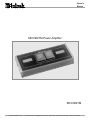
Owners Manual MCC602TM Power Amplifier MCC602TM McIntosh Laboratory, Inc. 2 Chambers Street Binghamton, New York 13903-2699 Phone: 607-723-3512 FAX: 607-724-0549 WARNING - TO REDUCE RISK OF FIRE OR ELECTRICAL SHOCK, DO NOT EXPOSE THIS EQUIPMENT TO RAIN OR MOISTURE. NO USER-SERVICEABLE PARTS INSIDE. REFER SERVICING TO QUALIFIED PERSONNEL. To prevent the risk of electric shock, do not remove bottom cover. No user serviceable parts inside. IMPORTANT SAFETY INSTRUCTIONS! PLEASE READ THEM BEFORE OPERATING THIS EQUIPMENT. General: 1. Read these instructions. 2. Keep these instructions. 3. Heed all warnings. 4. Follow all instructions. 5. Warning: To reduce risk of fire or electrical shock, do not expose this equipment to rain or moisture. This unit is capable of producing high sound pressure levels. Continued exposure to high sound pressure levels can cause permanent hearing impairment or loss. User caution is advised and ear protection is recommended when playing at high volumes. 6. Disconnect this equipment when unused for long periods of time. 7. Only use attachments/accessories specified by the manufacturer. Installation: 8. Do not block any ventilation openings. Install in accordance with the manufacturers instructions. 9. Do not install near any heat sources such as radiators, heat ducts or other equipment that produce heat. 10. Do not use this equipment near water. 11. Do not expose this equipment to dripping or splashing and ensure that no objects filled with liquids are placed on the equipment. 12. Do not mount this product with an unstable bracket as the equipment may fall, causing serious injury to a person, and serious damage to the product. Connection: 13. Route DC power cords so that they are not likely to be pinched by items placed upon or against them, paying particular attention to the point where they enter the instrument. 2 Care of Equipment: 14. Clean only with dry cloth. 15. Do not permit objects or liquids of any kind to be pushed, spilled and/or fall into the equipment through enclosure openings. Repair of Equipment: 16. Refer all servicing to qualified service personnel. Servicing is required when the equipment has been damaged in any way, such as power-supply cord or plug is damaged, liquid has been spilled or objects have fallen into the equipment, the equipment has been exposed to rain or moisture, does not operate normally, or has been dropped. 17. Do not attempt to service beyond that described in the operating instructions. All other service should be referred to qualified service personnel. 18. When replacement parts are required, be sure the service technician has used replacement parts specified by McIntosh or have the same characteristics as the original part. Unauthorized substitutions may result in fire, electric shock, or other hazards. 19. Upon completion of any service or repairs to this product, ask the service technician to perform safety checks to determine that the product is in proper operating condition. Thank You Table of Contents Your decision to own this McIntosh MCC602TM Two Channel Power Amplifier ranks you at the very top among discriminating music listeners. You now have The Best. The McIntosh dedication to Quality, is assurance that you will receive many years of musical enjoyment from this unit. Please take a short time to read the information in this manual. We want you to be as familiar as possible with all the features and functions of your new McIntosh. Safety Instructions ............................................................. 2 Thank You .......................................................................... 3 Please Take a Moment ....................................................... 3 Customer Service ............................................................... 3 Table of Contents ............................................................... 3 General Notes .................................................................... 3 Introduction ....................................................................... 4 Performance Features ........................................................ 4 Dimensions ........................................................................ 5 Installation ......................................................................... 6 Side Panel Cooling, Connections and Switch ................... 7 How to Connect for Two Channels ................................... 8 How to Connect for Mono Parallel ................................. 10 Top Panel Displays .......................................................... 12 How to Operate ................................................................ 13 How to Replace the Fuses ............................................... 14 Technical Description and Block Diagrams .................... 15 Specifications .................................................................. 18 Packing Instruction .......................................................... 19 Please Take A Moment The serial number, purchase date and McIntosh dealer name are important to you for possible insurance claim or future service. The spaces below have been provided for you to record that information: Serial Number: Purchase Date: Dealer Name: Technical Assistance If at any time you have questions about your McIntosh product, contact your McIntosh dealer who is familiar with your McIntosh equipment and any other brands that may be part of your system. If you or your dealer wish additional help concerning a suspected problem, you can receive technical assistance for all McIntosh products at: McIntosh Laboratory, Inc. 2 Chambers Street Binghamton, New York 13903 Phone: 607-723-1545 Fax: 607-723-3636 Customer Service If it is determined that your McIntosh product is in need of repair, you can return it to your dealer. You can also return it to the McIntosh Laboratory Service Repair department. For assistance on factory repair return procedure, contact the McIntosh Repair Department at: McIntosh Laboratory, Inc. 2 Chambers Street Binghamton, New York 13903 Phone: 607-723-3515 Fax: 607-723-1917 General Notes 1. Do not connect the Amplifier Speaker Negative Terminal Connection directly to the Vehicle Chassis. Failure to observe this could result in damage to your Amplifier. 2. For additional connection information, refer to the owners manual(s) for any component(s) connected to the MCC602TM Amplifier. 3. There is a built-in turn on delay which will mute the speaker outputs for approximately two seconds when the amplifier is turned on. 4. It is very important that loudspeaker cables of adequate size be used in your music system, to ensure that there will be no power loss or heating. Use at least 14 Gauge (AWG) wire size or larger. The speaker output terminals are large enough to accept 12 Gage wire. 5. It is advisable to place an in-line fuse as close as possible to the battery. 6. The pin configuration for the XLR Balanced Input connectors on the MCC602TM. Refer to the diagram for connections. PIN 1: Shield or ground PIN 2: (+) input Pin 1 Pin 2 PIN 3: (-) input 7. The MCC602TM can accept speaker level inputs at its Balanced Input Jacks. Refer to the diagram for connection. Pin 3 PIN 1: No connection PIN 2: Power Amplifier Output Connection (+) from the Control Center PIN 3: Power Amplifier Output Connection (-) from the Control Center Copyright 2000 ã by McIntosh Laboratory, Inc. 3 General Notes, cont 8. The MCC602TM incorporates the very latest in Fully Double Balanced Circuitry. As a result, the Loudspeaker Negative Connections are above chassis ground and are not common between channels. Do not combine any connections together or ground them. 9. In the event that MCC602TM Power Amplifier over heats, due to improper ventilation and/or extremely high ambient temperature, the built in protection circuits together with the built-in cooling fans will activate. The Power Guard LEDs will both continuously indicate On and no sound will be heard. When the temperature of the MCC602TM has returned to a safe condition, sound will return and the Power Guard Indictors will return to normal operation. circuit is possible ONLY with the exclusive McIntosh Output Autoformer. The Balanced Input Connections guard against induced noise and allow long cable runs without compromising sound quality. · Patented Autoformers McIntosh designed and manufactured Output Autoformers provide an ideal match between the amplifier output stages and speaker loads of 2, 4 and 8 ohms. The Autoformers also provide perfect DC protection for your valuable loudspeakers. · Power Guard Introduction Now you can take advantage of traditional McIntosh standards of excellence in the MCC602TM. Two 300 watt high current output channels will drive any high quality loudspeaker system to its ultimate performance. The MCC602TM reproduction is sonically transparent and absolutely accurate. The McIntosh Sound is The Sound of the Music Itself. Performance Features · Power Output The MCC602TM consists of two separate power amplifier channels, each capable of 300 watts into 2, 4 or 8 ohm loudspeakers with less than 0.005% distortion. · Mono Parallel Operation The MCC602TM can be set in Mono Parallel Operation with 600 watts output into 1, 2, or 4 ohm loudspeakers with less than 0.005% distortion. It can also function as two 300 watt amps both amplifying the same mono input signal. · High Current Output A peak output current of 50 amperes ensures that the MCC602TM will successfully drive high quality loudspeakers, such as McIntosh, for a truly exciting sound experience. · Fully Balanced Circuitry The MCC602TM amplifier is fully balanced from input to speaker output. Two matched amplifiers operate in PUSHPULL with their outputs magnetically combined in the Output Autoformer. Each half of the amplifier contains complementary balanced circuitry. The resulting double balanced configuration cancels virtually all distortion. This 4 Both channels include the patented McIntosh Power Guard circuit that prevents the amplifier from being over driven into clipping, with its harsh distorted sound that can also damage your valuable loudspeakers. · Sentry Monitor McIntosh Sentry Monitor power output stage protection circuits ensure the MCC602TM will have a long and trouble free operating life. · Thermal Protection with Multi-Speed Cooling Fans Built-in thermal protection circuits guard against overheating which could shorten the normal long life expectancy of your McIntosh power amplifier. Cooling fan speed is controlled by temperature sensors attached to the interior of the extruded aluminum cooling tunnel. The fans normally run at a quiet low speed, when needed the fans will automatically switch to a higher speed for increased cooling. · Illuminated Power Meters The Illuminated Power Output Watt Meters on the MCC602TM are peak responding and almost ten times faster than a professional VU meter. They also indicate the true power output of the amplifier regardless of the loudspeaker impedance, as they measure both the voltage and current going to them. General Notes cont, Introduction, Performance Features and Dimensions Dimensions The following dimensions can assist in determining the best location for your MCC602TM. There is additional information on the next page pertaining to installing the MCC602TM into your vehicle. Top View of the MCC602TM 26-7/8" 68.3cm 23-47/64" 60.29cm 16-7/8" 42.89cm 10-1/32" 25.46cm 3-11/16" 8.05cm 12-1/2" 31.75cm 11-7/8" 31.15cm Side View of the MCC602TM 11" 27.93cm 8" 20.32cm 2-15/16" 7.52cm 4-3/16" 11/32" 10.93cm 2-15/16" 10.64cm 7.49cm 5 Installation It is recommended that a professional who is skilled in all aspects of installation and operation install the MCC602TM and any associated mobile audio equipment. Amplifier Ventilation Always provide adequate ventilation for the MCC602TM. The amplifier requires an adequate airflow into the cooling fans, which are located on the left side of the amplifier. The warm air exits the amplifier through vents on the heatsinks. See figure 1. Be sure to provide at least 1-1/2 Cool Air inches clearance in front of the cooling fans and 1 inch clearance at the sides of the heatsinks. Figure 1 The cooling fans are controlled by temperature sensors, attached to the interior of the tunnel. The fans are normally off. If the program material contains sustained loud pas- Cool Air sages demanding high power, the fans will turn-on to increase cooling. If cooling is still not sufficient, additional heating will shut down the amplifiers internal power supply completely and the Power Guard LEDs will light. The fans will continue to run and once normal temperature is restored, operation will resume. The amplifier can be mounted vertically or horizontally and may be located under a seat if adequate clearance is available. The preferred installation method is to mount the am- Figure 2 plifier directly to the vehicle main frame using the hardware supplied with the amplifier. It is not recommended that the amplifier be mounted under the hood or in a location where it will be directly exposed to the elements. The openings in the fan housings and heat tunnel vents can allow internal components to be damaged by exposure to water, chemicals or any form of road dust or debris. Removing the Glass Panel Remove the eight hex bolts with the supplied 3/32 hex key from the MCC602TM Top Glass Panel. See figure 2. Attach the supplied suction cup to either side of the top glass panel and carefully raise it high enough to put your hand under. Temporarily place the removed glass panel in a safe place, remove the suction cup and save it for future use. Removing the End Caps To access the MCC602TM Connecting Terminal Blocks, remove the Glass Panel first (the above step) and then remove the Phillips Screws holding the End Caps on both sides of the amplifier and lift the end caps off. See figure 3. Warm Air Warm Air Remove Top Cover Screws Remove Top Cover Screws Remove End Cap Screws Figure 3 Remove End Cap Screws 6 Installation, Side Panel Cooling, Connections, Controls and Switch Left Side View Connect to the Negative (-) vehicle battery terminal Connect to the positve (+) vehicle battery terminal with an inline fuse Cooling Fan Air Intake Cooling Fan Air Intake Right Side View CHANNEL 1 OUTPUT Connections for 2, 4 or 8 ohm loudspeakers CHANNEL 2 OUTPUT Connections for 2, 4 or 8 ohm loudspeakers BALANCED INPUT for audio cables from control center audio outputs BALANCED INPUT for audio cables from control center audio outputs CHANNEL 1 UNBALANCED INPUT for audio cables from control center audio output CHANNEL 1 SENSITIVITY Input Sensitivity Control MODE Switch selects Stereo or Mono Parallel Mode Controls the Power Guard Circuit when connected to certain McIntosh Control Centers CHANNEL 2/MONO UNBALANCED INPUT for audio cables from control center audio output CHANNEL 2/MONO SENSITIVITY Input Sensitivity Control Receives the Amplifier Turn-ON signal from a McIntosh Control Center 7 How to Connect for Two Channels 1. Connect the power control cable from the Control Center Amp ON to the MCC602TM ON Connector on the right side of the Amplifier. Left Tweeter Left Woofer/Midrange Note: All cables should be connected to the amplifier before connecting the DC power cables to the battery. 2. Connect a cable from a McIntosh Control Center with Power Guard to the MCC602TM PG Connector on the right side of the amplifier. 3. Connect the CHANNEL 1 4(-) Ohm OUTPUT of the Power Amplifier to the Crossover Network Negative (-) Input Terminal and the CHANNEL 1 4(+) Ohm OUTPUT to the Crossover Network (+) Input Terminal. Connect the CHANNEL 2 OUTPUTs to the second Crossover Network in a similar manor. 4. Connect the cables from the Crossover Network to the respective Woofer/Midrange Terminals, for both channels. 5. Connect the cables from the Crossover Network to the Tweeter Terminals, for both channels. 6. Connect audio cables from the Control Center Front Outputs to the appropriate MCC602TM Inputs. 7. Connect the MCC602TM DC input terminals on the left side of the amplifier to the vehicle battery terminals using a minimum size of 4 AWG cables. Note: It is advisable to place an in-line fuse as close as possible to the battery. McIntosh Control Center Left Front Output Right Front Output Power Guard (orange) Amp ON (blue/white) 8 How to Connect for Two Channels Left Crossover Network (4 Ohms) Right Crossover Network (4 Ohms) - Vehicle + Battery Right Woofer/Midrange Right Tweeter Fuse 9 How to Connect for Mono Parallel 1. Connect the Power Control Cable from the Control Center Amp ON to the MCC602TM ON connector on the right side of the amplifier. Note: All cables should be connected to the amplifier before connecting the DC power cables to the battery. 2. Connect a cable from a McIntosh Control Center with Power Guard to the MCC602TM PG connector on the right side of the amplifier. 3. Connect cables from the amplifiers CHANNEL 2 (+) and (-) OUTPUT terminals to the CHANNEL 1 (+) and (-) OUTPUT terminals. Note: In Mono Parallel Mode, the impedance presented to the speaker is half of the number marked on the terminals, refer to the Mono Parallel Hookup Connections chart. 4. Connect a cable from a first Subwoofers (+) and (-) Terminals to the Amplifiers (+) and (-) Terminals of the CHANNEL 2 OUTPUT. 5. Connect a cable from the first Subwoofers (+) and (-) Terminals to the Second subwoofers (+) and (-) Terminals. 6. Connect audio cables from a McIntosh Control Center to the INPUTs of a McIntosh Crossover Network. 7. Connect audio cables from the McIntosh Crossover Network SUB OUTPUT to the MCC602TM 2/MONO Input. PARALLEL, both channels can be fed from the 2/MONO Input and each drive a separate speaker. In this case the speakers are connected as described in the HOW TO CONNECT FOR TWO CHANNEL section of this manual on page 8. 0RQR3DUDOOHO+RRNXS&RQQHFWLRQV 6SH D NHU 6S H DNH U 1HJ D WL YH 6S HD NH U 3R V L WL YH ,PSH GD QFH & R QQH FWLR Q & R QQH FWL RQ & + $ 11 ( / 6 & + $ 11 ( / 6 R KPV RKPV R KPV D QG D QG 2 8 73 8 7 2 8 73 8 7 R KP R KP & R QQH F W L R QV & R QQH F W L R QV & + $ 11 ( / 6 & + $ 11 ( / 6 D QG D QG 2 8 73 8 7 2 8 73 8 7 R KP R KP & R QQH F W L R QV & R QQH F W L R QV & + $ 11 ( / 6 & + $ 11 ( / 6 D QG D QG 2 8 73 8 7 2 8 73 8 7 R KP R KP & R QQH F W L R QV & R QQH F W L R QV McIntosh Control Center Left Front Output Right Front Output Power Guard (orange) Amp ON (blue/white) McIntosh Crossover Network Note: Do not connect a cable to the LEFT input. 8. Connect the MCC602TM DC input terminals to the vehicle battery terminals using a minimum size of 4 AWG cables. Note: It is advisable to place an inline fuse of sufficient size as close as possible to the battery. An alternative configuration is, when the MCC602TM is set for MONO 10 How to Connect for Mono Parallel Woofer (4 Ohm) - Woofer (4 Ohm) + - - Vehicle + Battery + Fuse 11 CHANNEL 1 POWER GUARD LED lights when the Power Guard Circuit activates for Amplifier Channel 1 CHANNEL 1 METER indicates the Channel 1 Power Output 12 CHANNEL 2 POWER GUARD LED lights when the Power Guard Circuit activates for Amplifier Channel 2 CHANNEL 2 METER indicates the Channel 2 Power Output Top Panel Displays and How to Operate the MCC602TM Introduction The McIntosh MCC602TM is a highly versatile amplifier that can be configured in many ways. This manual gives examples of some of the most common configurations and will guide you through the basic operation, however we suggest you refer to your dealer for further information on the use of this unit. Power The MCC602TM will turn On or Off when the Control Center turns On or Off. Note: There must be an Amp ON connection between the MCC602TM and the signal source unit in order for the amplifier power turn On and Off to function. Input Sensitivity Controls The SENSITIVITY controls allow the setting of the input sensitivity, of both amplifier channels, to provide an ideal match for the signal source being used. The most desirable setting allows the Control Center to have a useful volume range as wide as possible from loud to soft. A good place to start is to set the amplifiers SENSITIVITY Control to the output voltage called out in your control center owners manual. The Sensitivity Figure 4 Controls can be set for any sensitivity from 1 volts to 8 volts. Refer to figure 4. Power Output Meters There are two illuminated watt meters on the glass panel, displaying the power output for both channels. The upper scale shows power in Watts, the lower scale displays the power in Decibels (dB). The meters respond to all the musical information beFigure 6 ing produced by the amplifier. They indicate to an accuracy of at least 95% of the power output with only a single cycle of a 2000Hz tone burst. Refer to figure 6. Note: When used in conjunction with a McIntosh control center, you may find setting the Sensitivity controls to the center detent (2V) works best. In Mono Parallel Mode the Input SENSITIVITY Control for the CHANNEL 2/MONO channel is used and the SENSITIVITY Control for CHANNEL 1 is inoperative. Mode Switch In the Mono Parallel Mode, the two channels are tied together allowing the amplifier to operate as one full frequency range 600-watt amplifier. A typical Mono Mode application is to drive a Figure 5 subwoofer. Refer to figure 5. 13 How to Replace the Fuses How to Replace the Fuses If the MCC602TM produces no sound, no Meter Illumination, the power control and the power supply connections seem secure, one or more of the Amplifier Fuse(s) may have failed. Under normal operating conditions your amplifiers fuses should not fail. Failure of a fuse is usually an indication of a problem. Replacing the fuse, if there is problem in the amplifier, may incur a risk of further damage. Figure 7 Refer to figures 7, 8 and 9. Remove Top Cover Screws Caution: Disconnect the Amplifier from the Vehicle Battery ( or DC Power Supply) as Potentially Dangerous Currents exist inside the amplifier. 1. Before accessing fuses, disconnect both the positive and negative power cables from the DC input terminals on the left side of the amplifier using a 5/32 hex key. 2. Remove the Top Glass Panel by first removing the eight hex bolts with the supplied 3/32 hex key. 3. Attach the supplied suction cup to either side of the top glass panel and carefully raise it high enough to put your hand under. Temporarily place the removed glass panel in a safe place, remove the suction cup and save it for future use. 4. Remove the Phillips Screws holding the End Caps on both sides of the amplifier and lift the end caps off. 5. Remove the fuses with needle nose pliers, taking care to avoid hitting the wattmeter during removal. Do not lever the pliers against the wattmeter. Remove Top Cover Screws Remove End Cap Screws Figure 8 Remove End Cap Screws Location of the four fuses Note: To determine if the fuse has failed, examine the link between the two fuse legs to see if it has a break in it. 6. Replace the fuse with one of the same type and rating as unauthorized substitutions may prove hazardous to you and the amplifier. 7. When reinserting the fuse, set it in place with the pliers, then push it the rest of the way in with your finger to avoid having the pliers slip and hit the circuit board. 8. Reinstall the Top Glass Panel. 9. Reconnect the power cables to the vehicle battery. If the replacement fuse(s) fails again, have the amplifier repaired at a McIntosh Service Center. 14 Figure 9 Technical Description Technical Description McIntosh Laboratory, the company who introduced the worlds first amplifier over fifty years ago that could be called High Fidelity, has done it again. The McIntosh engineering staff has created a power amplifier without compromise, using the most advanced McIntosh circuit design concepts. A continuous average power output rating of 300 watts and with an output current of greater than 50 amperes per channel, makes this not only the most advanced, but also the most powerful amplifier McIntosh has ever manufactured. The distortion limits for the MCC602TM are no more than 0.005% at rated power output for all frequencies from 20Hz to 20,000Hz. Typical performance at mid frequencies is less than 0.002%. The true distortion readings on the MCC602TM are so low, it takes special measuring techniques to make accurate readings. The MCC602TM can deliver the best possible performance from any type of high quality loudspeaker system. Creating an amplifier with this level of performance did not come easily. Many months of design, testing and measuring were required. Extensive controlled listening tests, the ultimate form of measuring, were made before the final design was accepted. Design Philosophy The design philosophy incorporated in the MCC602TM involved several different techniques, all based on sound scientific logic. Every stage of voltage or current amplification must be as linear as possible prior to the use of negative feedback. McIntosh engineers know how to properly design negative feedback circuits so they contribute to the extremely low distortion performance expected from a McIntosh amplifier. The typical McIntosh owner would never accept the approximately 100 times higher distortion of many non-feedback designs. Double Balanced Push Pull design is used from input to output. Each half of the amplifier contains complimentary balanced circuitry. The resulting double balanced configuration cancels even order distortion. Refer to figure 11 on page 18. All transistors are selected to have nearly constant current gain over the entire current range they must cover. Output transistors in particular, have matched uniform current gain, high current-bandwidth product and large active region safe operating area. An automatic tracking bias system completely eliminates any trace of crossover distortion. All the resistors are Precision Metal Film types and low dielectric absorption film capacitors are used in all critical circuit locations. The output signals of the two balanced circuits are coupled together in the unique McIntosh MCC602TM Output Autoformer. It provides low distortion power transfer at frequencies from below 20Hz to well beyond 20,000Hz with optimum impedance points of two ohms, four ohms and eight ohms. The unequaled expertise of McIntosh in the design and manufacturing of autoformers is legendary in the high fidelity industry. The high efficiency circuit design of the MCC602TM contributes to low operating temperatures. McIntosh amplifiers are constructed in an extruded aluminum tunnel that has exhaust ports along its length. These exhaust ports are tuned to provide even air flow, over the surface of the tun- Inside the MCC602TM 15 nel cooling fins. Temperature sensors, attached to the interior of the tunnel, control the cooling fans. The fans are normally off; if the program material contains sustained loud passages demanding high power, the fans will turn on to increase cooling. Autoformers All solid state power amplifier output circuits work best into what is called an optimum load. This optimum load may vary considerably from what a loudspeaker requires. In the case of more than one loudspeaker connected in parallel, the load to the power amplifier may drop to two ohms or even less. A power amplifier connected to a load that is lower than optimum, causes more output current to flow, which results in extra heat being generated in the power output stage. This increase in temperature will result in a reduced life Figure 10 expectancy for the amplifier. The Autoformer creates an ideal match between the power amplifier output stage and the loudspeaker. Refer to figure 10. A McIntosh amplifier with an Autoformer can be used to safely drive multiple speakers without reducing the life expectancy of the power amplifier. There is absolutely no performance limitation with an Autoformer. Its frequency response exceeds that of the output circuit itself, and extends well beyond the audible range. Its distortion level is so low it is virtually impossible to measure. In the rare event of a power amplifier output circuit failure, the McIntosh Autoformer provides absolute protection from possible damage to your valuable loudspeakers. The unequaled expertise of McIntosh in the design and manufacturing of Autoformers is legendary in the high fidelity industry. McIntosh Figure 12 Block Diagram of both Amplifier Channels Figure 11 16 Technical Description, cont engineers know how to do it right. Protection Circuits The MCC602TM incorporates its version of the McIntosh Sentry Monitor output transistor protecInput Test Signal tion circuit. Refer to figure 12. There is absolutely no compromise in sonic performance with this circuit, and it ensures safe operation of the amplifier under even the most extreme operating conditions. The different types of protection circuits incorporated in the MCC602TM insure a long and safe operating life. Figure 13 This is just one of the many characteristics of McIntosh Power Amplifiers that Without Power Guard make them world famous. The MCC602TM also includes the unique patented McIntosh POWER GUARD circuit. Power Guard eliminates the possibility of ever overdriving the amplifier into clipping. Refer to figures 13, 14 and 15. An overdriven amplifier can produce both audible and inaudible distortion levels exceeding Figure 14 40%. The audible distortion is unpleasWith Power Guard ant to hear, but the inaudible ultrasonic distortion is also undesirable, since it can damage valuable loudspeaker system tweeters. You will never experience the harsh and damaging distortion due to clipping. The POWER GUARD circuit is a waveform comparator, monitoring both the input and output waveforms. Under Figure 15 normal operating conditions, there are no differences between the shape of these waveforms. If an amplifier channel is overdriven, there will be a difference between the two signal waveforms. When the difference exceeds 0.3% (equivalent to 0.3% harmonic distortion), the POWER GUARD activates the PG light and a dynamic electronic attenuator at the amplifier input reduces the input volume just enough to prevent any further increase in distortion. The POWER GUARD circuit acts so fast that there are absolutely no audible side effects and the sonic purity of the music reproduction is perfectly preserved. The MCC602TM Power Amplifier with POWER GUARD is not limited to just the rated power output, but will actually produce distortion free output well above its rated power due to the McIntosh philosophy of conservative design. Power Supply The high efficiency Pulse Width Modulation Regulated Power Supply operates with 85% efficiency and features MOSFET power transistors switching at 40KHz. Refer to figure 16. The power supplies are independent for each channel. Regulation is maintained from 12 to 16 volts at the battery input. The turn-on inrush current is cushioned, by a soft start circuit in the power supply which eliminates component stress during turn-on. Accidental blockage of the cooling intake port or some other fault condition could cause the amplifier temperature to continue to rise, even with the fan at full speed. A temperature sensing circuit in the power supply will reduce heat dissipation by lowering the voltage to the amplifier. If cooling is still not sufficient, additional heating will shut down the power supply completely. The fan will continue to run and once normal temperatures are restored, operation will resume. Power Supply Figure 16 17 Specifications Specifications Power Output Stereo Minimum sine wave continuous average power output per channel, all channels operating is: 300 watts into 2 ohm load 300 watts into 4 ohm load 300 watts into 8 ohm load Power Requirements 12 Volts DC, 3.5 amps (idle) - 100 amps (600 watts) Power Output Mono Minimum sine wave continuous average power output per channel, all channels operating is: 600 watts into 1 ohm load 600 watts into 2 ohm load 600 watts into 4 ohm load Weight 50.5 pounds (22.9 Kg) net, 58.5 pounds (26.5 Kg) in shipping carton Rated Power Band 20Hz to 20,000Hz Total Harmonic Distortion Maximum Total Harmonic Distortion at any power level from 250 milliwatts to rated power output is: 0.005% for 2, 4 or 8 ohm loads (Stereo) 0.005% for 1, 2 or 4 ohm loads (Mono) Dymanic Headroom 1dB Frequency Response +0, -0.25dB from 20Hz to 20,000Hz +0, -3dB from 10Hz to 50,000Hz Sensitivity 1Volt balanced or unbalanced inputs A-Weighted Signal To Noise Ratio 114dB (2V) Intermodulation Distortion Maximum Intermodulation Distortion if instantaneous peak output per channel does not exceed twice the rated output, for any combination of frequencies from 20Hz to 20,000Hz, with all channels operating is: 0.005% for 2, 4 or 8 ohm loads (Stereo) 0.005% for 1, 2 or 4 ohm loads (Mono) Input Impedance 15,000 ohms balanced or unbalanced inputs 18 Dimensions 26-7/8 inches (68.3cm) wide, 12-1/2 inches (31.75 cm) depth, 4-3/16 inches (10.64 cm) high Packing Instructions Packing Instructions In the event it is necessary to repack the equipment for shipment, the equipment must be packed exactly as shown below, failure to do so will result in shipping damage. Make sure that the Top Glass Panel is firmly secured to the chassis using the supplied hex head screws. Use the original shipping carton and interior parts only if they are all in good serviceable condition. If a shipping carton or any of the interior part(s) are needed, please call or write Customer Service Department of McIntosh Laboratory. Please see the Part List for the correct part numbers. Quantity 1 2 1 Part Number 034140 034141 034142 Description Shipping carton only End cap (Foam pad) Center Support (Foam pad) 19 McIntosh Laboratory, Inc. 2 Chambers Street Binghamton, NY 13903 McIntosh Part No. 040730