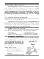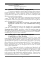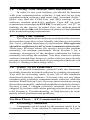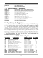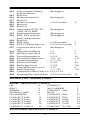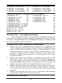
1
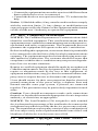
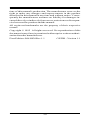
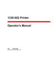
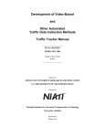
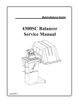
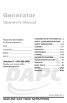
High Performance
V.32bis/V.42bis
14,400 BPS Internal
Plug and Play
FAX/Voice/Data
Modem
Featuring Advanced FullDuplex Speakerphone
Functions
User's Manual
Contents
Section One
Section Two
Section Three
Section Four
Section Five
Section Six
Section Seven
Section Eight
Section Nine
Introduction ........................... 1
Installation ............................. 1
AT Command Set .................. 4
S Register Summary ........... 12
Result Codes ......................... 13
Troubleshooting ................... 14
Specifications ....................... 16
Support And Service ........... 16
FCC, DOC, Copyright And
Other Notices ....................... 17
Part #49.AA808.001
ACER 14.4 TAD-SP 1.xx
Section One - Introduction
This 14.4 Kbps FAX/Voice/Data Modem is specifically designed for the Acer Aspire line of computers, enabling
their connection to all popular high speed modems available
today. Your new modem features advanced speakerphone
functions for hands-free voice communication as well as Plug
and Play for simplified installation. This manual describes
the hardware installation procedures for your new modem
product. Additional information on AT commands and Sregisters are provided so that your system can be customized
for a particular operating environment.
Section Two - Installation
This section will provide step by step instructions on
how to install your new 14.4 Kbps FAX/Voice/Data modem.
Installation of this modem product is a two-step process
consisting of actual hardware installation and communication software installation and configuration.
2.1 Unpacking Your Modem
Before you begin your installation, be certain that you
have all the items listed below. This package contains:
• A modem
• A telephone cable
• User's manual
• Configuration software
• Software for the modem • Software user's manual
2.2 Hardware Installation
Installation of this modem requires opening and manipulating your PC. Exercise caution at all times when
working with AC powered and static-sensitive equipment.
Turn off and unplug your PC beFigure 2-1
fore installation. Discharge any
Expansion
static electricity from your body
Slots
by touching any bare metal surface of the PC system, such as its
power supply cover.
1.
2.
3.
Turn off and unplug your computer from the AC outlet.
Remove your computer's cover
(refer to your computer's owner
manual).
Select any available half-card
1
slot, and then remove the
Figure 2-2
slot cover (refer to Figure 2-1).
4. Carefully slide the internal modem into the
slot you have chosen,
applying even pressure
until the modem is completely seated in the slot.
5. Fasten the retaining
bracket with the screw
Mic/Speaker connector
from the slot cover.
Make sure the modem is properly aligned. Figure 2-3
Store the slot cover for future use.
6. Connect the computer sound card's microPHONE
phone/speaker interconnector plug to the
modem's mic/speaker connector (See figure 2-2).
LINE
7. Replace the computer cover and plug in
your computer.
8. Connect the telephone cable from the
MIC
modem's LINE connector (See figure 2-3)
to the telephone wall jack.
9. Optionally connect your telephone to the
modem's PHONE connector (See figure
2-3).
10. Connect the microphone plug into the MIC jack (See figure
2-3).
11. Connect your powered speaker(s) into the Line Out jack of
the sound card.
12. Turn your computer on. Your modem is now installed.
2.3 Plug and Play
Your modem supports Plug and Play (PnP) and can
easily be configured using any Plug and Play compliant PC.
Your PC is PnP compliant if you have: 1) an operating system
that supports Plug and Play, and 2) PnP BIOS/chipset.
In a PnP compliant operating system (e.g. Windows ®
95), follow the instructions included with the operating
system to configure Plug and Play cards.
On Acer pre-configured systems with this modem and
Windows 95 software, this modem has been set to:
'MODEM'
Sierra 14.4 Data Fax Voice SQ3230
2
COM 1, IRQ 4
'MODEM VOICE'
Sierra 3230 (Voice)
DMA 3, IRQ 10
2.4 Software Installation/Configuration
You are now ready to install and configure the communication software. Refer to your software manual for installation procedures. Your software must be configured to
communicate with the modem on the same COM port and
IRQ line used by the modem.
We suggest the following communication parameters
when you first use your data communication software.
Consult the software manual for information on using these
and other parameters/features.
38,400 bps; 8 data bits; no parity; 1 stop bit; RTS/
CTS flow control set to “on;” initialization string:
AT&F
The commands used by the modem are compatible
with the command set used by the “Hayes V-series Ultra
Smartmodem 14400” modems, select this modem type in
your data communications software. Select a “Generic Class
2” modem type in your FAX software and select a “Sierra”
modem type in your voice software.
2.5 Using Fax, Voice, and Speakerphone
Capabilities of the Modem
Your modem has built-in advanced FAX, Voice, and
Full Duplex Speakerphone functions. These functions are
accessed through software. Please consult your FAX/Voice/
Speakerphone software manual about procedures on using
these functions. Note that the modem's FAX/Voice/Speakerphone commands are used by the software to implement
these functions and are not designed to be used as standalone AT commands.
Voice functions include recording and playback of
voice prompts (files). You may record or playback voice with
your modem by attaching a telephone to the RJ-11 jack
marked "PHONE" or by attaching a microphone to the MIC
jack located on the back of the modem bracket. Then follow
instructions in the FAX/Voice/Speakerphone software on
recording and playback of voice prompts.
3
2.6 Testing Your Modem After Installation
In order to test your modem you should be familiar
with your communication software. Load and set up your
communication software and enter into “terminal mode.”
Make sure that the COM Port and IRQ settings of the
software modem match the modem. Type AT on your
terminal screen and press ENTER. You may see “AATT” or
nothing on the screen. In either case, the modem should
respond with an OK or 0. If it does not, please refer to Section
6 for troubleshooting information.
2.7 Using Your Modem
The communication software included with your modem product provides a user friendly interface to access the
fax, voice, and data functions of your modem. This software
should be sufficient for all of your communication needs.
There may be times when you need to access the modem
manually via modem commands. Read Section 3 for a
summary description of the modem command set before
manually accessing the modem. You may want to read the
software manual first, however, as the software may already
provide a user friendly method of accessing the functions you
need (i.e. dialing or answering calls).
2.8 Where To Go From Here
You should familiarize yourself with the functions
available from the included software by reading its manual.
You will be accessing most, if not all, of the modem's
functions from this software. You may also use any other
commercially available communication software with the
modem. Read Section 3 only if you are interested in accessing
the modem manually, and not through the included software.
Section 4 and 5 contain reference material, and can be
skipped. If you have difficulties getting your modem to work,
read Section 6, Troubleshooting, to find answers to commonly asked questions and problems.
Section Three - AT Command Set
3.1 Executing Commands
Commands are accepted by the modem while it is in
Command Mode. Your modem is automatically in Com-
4
mand Mode until you dial a number and establish a connection. Commands may be sent to your modem from a PC
running communication software or any other terminal devices.
Your modem is capable of data communication at rates
of: 300, 1200, 2400, 4800, 9600, 14400, 19200, 38400, and
57600 bps. Make sure your COM port baud rate setting in
your communications software is set to one of the above
speeds.
3.2 Command Structure
All commands sent to the modem must begin with AT
and end with ENTER. All commands may be typed in either
upper or lower case, but not mixed. To make the command
line more readable, spaces may be inserted between commands. If you omit a parameter from a command that
requires one, it is just like specifying a parameter of 0.
Example:
ATH [ENTER]
This command causes your modem to hang up.
3.3 Basic AT Commands
In the following listings, all default settings are printed
in bold text.
Command
Function
A
Manually answer incoming call
A/
Repeat last command executed. Do not precede
A/ with AT or follow with ENTER
AT
Appears at the beginning of every command
line
B_
B0
B1
B2
B3
D_
L
CCITT mode
Bell mode
With V.23, originate calls transmitting at 75
bps, receiving at 1200 bps. Answer calls
transmitting at 1200 bps, receiving at 75 bps.
With V.23, originate calls transmitting at 1200
bps, receiving at 75 bps. Answer calls
transmitting at 75 bps, receiving at 1200 bps
0 - 9, A-D, # and *
last number redial
5
P
T
W
,
DS=n
E_
pulse dialing
touch-tone dialing
wait for second dial tone
pause
@ wait for five seconds of silence
! flash
; return to Command Mode after dialing
: return to Command Mode after dialing
and maintain connection
Dial one of the four telephone numbers (n=03) stored in the modem’s non-volatile memory
E0
E1
+++
Commands are not echoed
Commands are echoed
TIES Escape Characters - Switch from Data
Mode to Command Mode
H_
H0
H1
Force modem on-hook (hang up)
Force modem off-hook (make busy)
I_
I0
I1
I2
I3
I4
I6
Display 14400
Display 000
Internal memory test
Firmware revision number
Configuration settings
DSP
L_
L0
L1
L2
L3
Low speaker volume
Low speaker volume
Medium speaker volume
High speaker volume
M_
M0
M1
M2
M3
Internal speaker off
Internal speaker on until carrier detected
Internal speaker always on
Internal speaker on until carrier detected and
off while dialing
N_
N0
N1
Line speed set by register S37.
Originate with automatic rate negotiation
starting at S37 setting, answer at any speed.
Adds V.23 to N1
Originating line speed set via register S37
Same as N3
Originate with automatic rate negotiation
starting at S37 setting, Anwer only at S37
setting
N2
N3
N4
N5
O_
O0
Return to Data Mode
6
O1
Return to Data Mode and initiate an equalizer
retrain
Q_
Q0
Q1
Q2
Modem sends responses
Modem does not send responses
Modem sends responses in originate mode but
not in answer mode
Sr?
r=0-30 Read and display value in register r
P
Set Pulse dial as default
Sr=n
Set register r to value n (r=0-30; n=0-255)
T
Set Tone Dial as default
V_
V0
V1
Numeric responses
Word responses
W
W0
W1
Report Connect at DTE speed only.
Report Connect at DTE speed with negotiation
progress
Report Connect at DCE speed only
X_
X0
W2
X1
X2
X3
X4
Y_
Y0
Y1
Z_
Z0
Z1
Hayes Smartmodem 300 compatible
responses/blind dialing
Same as X0 plus all CONNECT responses/
blind dialing
Same as X1 plus dial tone detection
Same as X1 plus busy signal detection/blind
dialing
All responses and dial tone and busy signal
detection
Modem does not send or respond to break
signals
Modem sends break signal for four seconds
before disconnecting
Reset and retrieve active configuration
profile 0
Reset and retrieve active configuration
profile 1
3.4 Extended AT Commands
&C_
&C0
&C1
Force Carrier Detect Signal High (ON)
Turn on Carrier Detect signal when remote
carrier signal is present
&D_
&D0
Modem ignores the Data Terminal Ready
signal
7
&D1
&D3
Modem returns to Command Mode after DTR
toggle
Modem hangs up, returns to the Command
Mode after DTR toggle
Resets modem after DTR toggle
&F_
&F0
&F3
Recall factory default configuration
Reset for extended responses
&G_
&G0
&G1
&G2
Guard tone disabled
550 Hz guard tone
1800 Hz guard tone
&K_
&K0
&K3
&K4
&K5
Disable DTE flow control
RTS/CTS flow control
XON/XOFF flow control
Transparent XON/XOFF flow control
&L_
&L0
&L1
Dialup telephone line
Leased Line
&M_
&M0 Asynchronous operation
&N_
&N0
&D2
&N1
&P_
&P0
&P1
Special echo canceller training sequence not
required
Special echo canceller training sequence
required
United States setting for off-hook (make) to-on-hook (break) ratio
UK and Hong Kong off-hook (make)-to-onhook (break) ratio
&Q_
&Q0
&Q5
&Q6
Asynchronous operation
Modem connects using MNP or V.42
Modem connects in Normal mode
&S_
&S0
&S1
Force DSR Signal High (ON)
DSR is off in command mode, on in on-line
mode
&T_
&T0
&T1
&T3
&T4
Ends test in progress
Perform Local Analog Loopback Test
Perform Local Digital Loopback Test
Grant Remote Digital Loopback Test
request by remote modem
Deny Remote Digital Loopback Test request
by remote modem
Perform a Remote Digital Loopback Test
Perform a Remote Digital Loopback Test and
Self-Test
&T5
&T6
&T7
8
&T8
Perform Local Analog Loopback Test and
Self-Test
&U_
&U0
&U1
Enable Trellis Coding @ V.32
Disable Trellis Coding @ V.32
&V_
&V0
&V1
Displays Active and Stored Profile 0
Displays Active and Stored Profile 1
&W_
&W0 Stores the active profile as Configuration
Profile 0
&W1 Stores the active profile as Configuration
Profile 1
&Y_
&Y0
&Y1
Configuration Profile 0 active upon Power
on or reset
Configuration Profile 1 active upon Power on
or reset
&Zn=x
n=0-3 Store telephone number x into non-volatile
RAM
%E_
%E0 V.22bis auto-retrain disabled
%E1 V.22bis auto-retrain enabled
3.5 MNP/V.42/V.42bis Commands
%An
n=0127
%C_
%C0 Disable MNP Class 5 data compression
%C1 Enable MNP Class 5 data compression
%D_
%D0 512 byte dictionary for V.42bis
%D1 1Kbyte dictionary
%D2 2 Kbyte dictionary
\C_
\C0
\C1
\C2
Set auto-reliable fallback character to n (where
n = 0 to 127,ASCII). Requires the \C2 setting
Do not buffer data during LAPM/MNP
handshaking
Buffer all data for 4 seconds, until receiving
200 characters or until a packet is detected
Do not buffer data; switch to normal mode
when fallback character is detected
\G_
\G0
\G1
Disable DCE flow control
Enable DCE flow control
\N_
\N0
\N1
\N2
\N3
\N4
\N5
Normal data-link only
Direct data-link only
MNP data link only
MNP/Normal data link
V.42 data link only
V.42/Normal data link
9
\Q_
\N6
V.42/MNP/Normal data link
\Q0
\Q1
\Q2
Turn off flow control
XON/XOFF software flow control
CTS signal unidirectional hardware flow
control
RTS/CTS signal bi-directional hardware
flow control
XON/XOFF unidirectionl flow control from
modem
\Q3
\Q4
\Tn
Inactivity timer, where n = 0 to 90 minutes.
Default is 0
\V_
\V0
\V1
Do not send extended responses
Send extended response set 1
\X_
\X0
\X1
Process XON/XOFF but don’t pass through
Process XON/XOFF and pass through
#CC_
#CC0 Caller ID disabled
#CC1 Formatted Caller ID (Date, Time Number)
#CC2 Unformatted Caller ID
3.6 Fax Class 2 Commands
+FAA=n
Data/Fax auto answer enable. Default is 0
+FBOR
Data Bit Order
+FBUF=?
Buffer Size
+FBUG
Session Message Reporting Parameter
+FCIG
Report Remote ID Response, CIG
+FCFR
Confirmation to Receive Prompt
+FCLASS
Service Class Identification and Control
+FCON
Facsimile Connection Response
+FCR
Capability to Receive
+FCSI
Report Remote ID Response Called Station
+FCSIG=n
Local Polling ID String
+FDCS:<string> Report Session Response
+FDCC=n
DCE Fax Capabilities Parameters
+FDIS:<string> Report Remote Capabilities Response
+FDIS=n
Current Session Negotiation
+FDR
Receive Phase C Data
+FDT[=]n
Transmit Phase C Data
+FDTC:
Report Remote Capabilities Response
+FET:
Post Page Message Response
+FET=n
End the Page or Document
+FHNG
Call Termination Status Response
+FHR:
Report Received HDLC Frame Response
+FHT:
Report Transmitted HDLC Frame
10
+FLID=n
+FMDL?
+FMFR?
+FPPR:
+FPTS:
+FPTS:
+FPTS=n
+FREV?
Local ID string (TSI/CSI)
Request DCE Model
Request DCE Manufacturer
Partial Page Report Response
Receive Page Transfer Status Response
Transmit Page Transfer Status Response
Page Transfer Status Parameter
Request DCE Revision
3.7 Voice Mode Commands
#VA=m
#VAA=n
#VB=f1,t
#VBL=n
#VBO=n
#VBS=n
#VC
#VCH=n
#VDR=e,r
#VD0
#VD1
#VF=n
#VG=n
#VH=n
#VL
#VM=n
#VNH=n
#VRA=n
#VRN=n
#VSC=n
#VSD=0,1,2
#VSI=n
#VSM=n
#VSn
#VSP=n
#VSR=n
#VSS=n
#VST
#VSV
#VTI=n
#VTn
Enable/disable AGC
Select auto-answer mode
Generate beep tone(f1=frequency,t=duration)
Sets voice buffer length control
Set binary offset mode
Specify data transfer via DMA
Disable, Enable <DLE><CAN> and DTMF
abort
Set DMA channel
Enable distinctive ring detection
Transmit voice data
Receive Voice Data
Set FIFO size
Gain setting in voice record mode
Energize relay
Set run-length encoding
Microphone command
Set hook behavior for fax and data calls within
voice calls
Ringback goes away timer
Ringback never came timer
Set compression mode to n
Silence deletion control (disable, 1 sec, .5 sec.)
Set silence end of message timer
Set CODEC mode to n
Activate voice mode (DTE rate n)
Set monitor mode
Enable actions and/or speakerphone response
codes
Set sample rate to n
Set silence threshold -43dBm/-47dBm
Transmit voice data, listen for DTMF and
CNG
Supervision point qualifier
Controls command mode DTMF and CNG
detection
11
#VTR=n
#VZ=n
:
Loop current interrupt qualifier
Set audio mode
Pager dial modifier
3.8 Speakerphone Commands
#SPC=n
#SPD=n
#SPF=n
#SPG=n
#SPL=n
#SPM=n
#SPT=n
#SPU=n
#SPV=n
#SPZ=n
#VM=n
Select AEC/EEC echo cancellation
Download speakerphone parameters
Select auto/fixed echo cancellation
Set microphone gain
Set DSP microphone gain
Enable speakerphone
Speakerphone forced train
Upload speakerphone parameters
Set speakerphone volume
Set microphone AGC
Set microphone status
Section Four - S Registers
Your modem has 39 registers, designated S0 through
S27, S36-S38, S46, S48-S50, S63, S82, S86, and S98. Table
4-1 shows the registers, their functions, and their default
values. Some registers can have their values changed by
commands. If you use a command to change a register value,
the command remains in effect until you turn off or reset your
modem. Your modem then reverts to the operating characteristics specified in its non-volatile memory. Refer to Section
3 for information on how to use the AT commands to
manipulate the S registers.
Table 4-1 S - Registers
Register
S0
S1
S2
S3
S4
S5
S6
S7
S8
S9
S10
S11
S12
Function
Range/units Default
Auto-answer Ring
Ring counter
Escape code character
Carriage return character
Line feed character
Backspace character
Dial tone wait time
Remote carrier wait time
Comma pause time
Carrier detect time
Carrier loss time
Touch-tone dialing speed
Esc. character detect time
12
0-255/rings
0
0-255/rings
0
0-127/ASCII
43
0-127/ASCII
13
0-127/ASCII
10
0-32, 127/ASCII
8
0-255/seconds
2
1-255/seconds
40
0-255/seconds
2
0-255/0.1 second
6
0-255/0.1 second
14
50-255/0.001 second 75
0-255/0.02 second 40
S13 Reserved
S14 Echo, response, dialing,
Bit-mapped
originate/answer
S15 Reserved
S16 Modem test options
Bit-mapped
S17 Reserved
S18 Modem test timer
0-255/seconds
S19 Reserved
S20 Reserved
S21 Auto retrain, RTS/CTS,
Bit-mapped
DTR, DCD, DSR
S22 Speaker and response
Bit-mapped
S23 RDL, DTE data rate,
Bit-mapped
parity,and guard tone
S24 Reserved
S25 DTR delay
0-100/seconds
S26 RTS/CTS delay interval
0-255/0.01 second
S27 Async operation, Line
Bit-mapped
type
S36 Negotiation Fallback
0-7
S37 Maximum line speed
0-11
S38 Forced hangup delay
0-255
S46 Select data compression
136, 138
S48 Feature negotiation
0, 7, 128
S49 Buffer lower limit
0-255
S50 Buffer upper limit
0-255
S63 Leased Line carrier level
0-15
S82 Break Signaling
3, 7, 128
S86 Connection failure code 0, 4, 9,10, 12-14
S98 Speakerphone squelch timer 0-255/.001second
0
5
1
7
0
20
138
7
10
200
0
128
10
Section Five - Result Codes
BASIC RESPONSE CODES
OK
RING
ERROR
NO DIALTONE
NO ANSWER
CONNECT 4800
CONNECT 9600
CONNECT 14400
CONNECT 38400
CONNECT 1200/75
0
2
4
6
8
11
12
13
28
22
CONNECT
NO CARRIER
CONNECT 1200
BUSY
CONNECT 2400
CONNECT 7200
CONNECT 12000
CONNECT 19200
CONNECT 57600
CONNECT 75/1200
EXTENDED RESPONSE CODES
13
1
3
5
7
10
24
25
14
29
23
CONNECT 0300/REL
CONNECT 2400/REL
CONNECT 9600/REL
CONNECT 38400/REL
16
18
20
26
CONNECT 1200/REL
CONNECT 4800/REL
CONNECT 19200/REL
CONNECT 57600/REL
17
19
21
27
NEGOTIATION PROGRESS CODES
CARRIER 300
40
CARRIER 75/1200
45
CARRIER 2400
47
CARRIER 7200
49
CARRIER 12000
51
COMPRESSION: CLASS 5
COMPRESSION: V.42BIS
COMPRESSION: NONE
PROTOCOL: NONE
PROTOCOL: LAP-M
PROTOCOL: ALT
CARRIER 1200/75
CARRIER 1200
CARRIER 4800
CARRIER 9600
CARRIER 14400
44
46
48
50
52
66
67
69
70
77
80
Section Six - Troubleshooting
This section describes some of the common problems
you may encounter while using your modem. If you can not
resolve your difficulty after reading this chapter, contact your
dealer or vendor for assistance.
Modem does not respond to commands.
1. Make sure the communication software is configured to
“talk” to the modem on the correct COM port and IRQ setting
(same COM port and IRQ setting as the modem). Your
communication software must know which address your
modem is using in the system in order to pass data to it.
Similarly, IRQ settings must be set correctly to receive data
from the modem.
2. Make sure that your modem is initialized correctly. Your
modem may have been initialized to not display responses.
You may factory-reset the modem by issuing AT&F and
press ENTER. The factory default allows the modem to
display responses after a command has been executed.
3. Make sure the baud rate setting in your software is set to
57600, 38400, 19200, 14400, 9600, 2400, 1200, or 300 bps.
An incorrect baud rate prevents the modem from operating
properly.
4. Make sure that the modem is not conflicting with another
COM port or IRQ in a non-PnP system.
Modem does not dial.
14
1. Make sure the modem is connected to a working phone line.
Replace the modem with a working phone to ensure that the
phone line is working.
2. Make sure the phone line is connected to the jack marked
“LINE.” Incorrect connection prevents the modem from
operating properly. Refer to Section 2.2 for modem connection instructions.
Modem dials but does not connect.
1. Make sure the IRQ setting is identical on both the modem and
the software in a non-Pnp system. Modem and software must
be configured identically.
2. Make sure the phone line is working properly. Replace the
modem with a regular phone and dial the number. If the line
sounds noisy, you may have difficulty connecting to the
remote device.
Modem makes a connection but no data appears
on your screen.
1. The remote system may be waiting to receive your data before
it begins. Try pressing the ENTER key a few times.
2. Make sure the correct data format (data bits, stop bits, and
parity bits) and flow control (RTS/CTS) method are being
used.
3. Make sure the correct terminal emulation mode is being used
(see communication software manual).
4. Make sure the modem is not sharing an IRQ or COM port with
another device in a non-PnP system.
High pitch tone is heard whenever you answer the
phone.
1. Make sure Auto-Answer is turned off. Your modem is factory
configured to NOT auto-answer. Issue AT&F to factory reset
your modem.
Modem experiences errors while communicating
with a remote modem.
1. Make sure the DTE speed is the same as the modem connection speed when in Direct Mode (\N1 command in effect).
2. Make sure the remote system and your modem use the same
communication parameters (i.e., baud rate, data bit length,
parity, and stop bit).
3. Make sure RTS/CTS hardware flow control is enabled and
XON/XOFF software flow control is disabled in the communication software.
4. Make sure the data speed is not faster than your computer's
15
capability. Most IBM compatibles are capable of 19,200 bps
under DOS and Windows. Operating at higher speeds under
Windows requires a faster CPU (386/486 or better).
Modem experiences bursts of errors or suddenly
disconnects while communicating with a remote
modem.
1. Make sure Call Waiting is turned off.
2. Make sure the phone line does not exhibit excess noise.
Modem exhibits poor voice record or playback.
1. Make sure the correct modem type is selected in the Voice/
FAX software. Use “Sierra” or similar selection. Do not
select “Rockwell or Rockwell ICS” configuration.
Section Seven - Specifications
CCITT/Bell Std.
V.42bis, V.42, V.32bis, V.32, V.29,
V.27ter, V.22bis, V.22, V.21, V.17,
Bell212/103
MNP protocols:
MNP 5, 4, 3, 2
Host Interface:
16-bit PC bus
COM ports:
1, 2, 3, 4
IRQ lines:
3, 4, 5, 7, 9, 10, 11, 12
FAX Group:
Group III Send/Receive Standard
FAX Command set: EIA/TIA-PN2388 Service Class 2
Voice Command set: Sierra
Escape Detection: TIES Escape Sequence
Transmit level:
-11 dBm +/- 1 dBm
Receiver Sensitivity: -43 dBm
UART:
16550 compatible
Data format:
300-57600 bps
Power:
0.75 W
Temperature:
0 to 55 degrees C (Operating); -20 to 80
degrees C (Non-operating)
Speakerphone:
Full-duplex with DSP echo cancellation
Plug and Play
ISA spec. V1.0a
Section Eight - Support and Service
In the unlikely event you experience difficulty in the use of this
product, we suggest you: (1) consult the Troubleshooting section
of this guide and (2) consult with your dealer. To obtain service for
this product, follow the Return Merchandise Authorization Procedure as outlined in the Warranty card.
16
Section Nine - FCC , DOC & Other Notices
9.1 FCC Compliance
This equipment complies with Part 68 of the FCC Rules. On this
equipment is a label that contains, among other information, the
FCC registration number and Ringer Equivalence Number (REN)
for this equipment. You must, upon request, provide this information to your telephone company.
If your telephone equipment causes harm to the telephone network, the Telephone Company may discontinue your service
temporarily. If possible, they will notify in advance. But, if
advance notice isn’t practical, you will be notified as soon as
possible. You will be informed of your right to file a complaint
with the FCC.
Your telephone company may make changes in its facilities,
equipment, operations, or procedures that could affect proper
operation of your equipment. If they do, you will be notified in
advance to give you an opportunity to maintain uninterrupted
telephone service.
The FCC prohibits this equipment to be connected to party lines or
coin-telephone service.
In the event that this equipment should fail to operate properly,
disconnect the equipment from the phone line to determine if it is
causing the problem. If the problem is with the equipment, discontinue use and contact your dealer or vendor.
The FCC also requires the transmitter of a FAX transmission be
properly identified (per FCC Rules Part 68, Sec. 68.381 (c) (3)).
9.2 FCC Class B Statement
This equipment has been tested and found to comply with the limits
for a Class B digital device, pursuant to Part 15 of the FCC Rules.
These limits are designed to provide reasonable protection against
harmful interference in a residential installation. This equipment
generates, uses and can radiate radio frequency energy, and if not
installed and used in accordance with the instructions, may cause
harmful interference to radio communications. However, there is no
guarantee that interference will not occur in a particular installation.
If this equipment does cause harmful interference to radio or
television reception, which can be determined by turning the equipment off and on, the user is encouraged to try to correct the
interference by one or more of the following measures:
• Reorient or relocate the receiving antenna
17
• Increase the separation between the equipment and the receiver
• Connect the equipment into an outlet on a circuit different from
that to which the receiver is connected
• Consult the dealer or an experienced radio / TV technician for
help
Notice: 1) Shielded cables, if any, must be used in order to comply
with the emission limits. 2) Any change or modification not
expressly approved by the Grantee of the equipment authorization
could void the user’s authority to operate the equipment.
9.3 DOC Compliance Information
NOTICE: The Canadian Department of Communications label
identifies certified equipment. This certification means that the
equipment meets certain telecommunications network protective,
operational and safety requirements. The Department does not
guarantee the equipment will operate to the user’s satisfaction.
Before installing this equipment, users ensure that it is permissible
to be connected to the facilities of the local telecommunications
company. The equipment must also be installed using an acceptable method of connection. The customer should be aware that
compliance with the above conditions may not prevent degradation of service in some situations.
Repairs to certified equipment should be made by an authorized
Canadian maintenance facility designated by the supplier. Any
repairs or alterations made by the user to this equipment, or
equipment malfunctions, may give the telecommunications company cause to request the user to disconnect the equipment.
Users should ensure for their own protection that the electrical
ground connections of the power utility, telephone lines and
internal metallic water pipe system, if present, are connected
together. This precaution may be particularly important in rural
areas.
Caution: Users should not attempt to make such connections
themselves, but should contact the appropriate electric inspection
authority, or electrician, as appropriate.
NOTICE: The Load Number (LN) assigned to each terminal
device denotes the percentage of the total load to be connected to
a telephone loop which is used by the device, to prevent overloading. The termination on a loop may consist of any combination of
devices subject only to the requirement that the sum of the Load
Numbers of all the devices does not exceed 100.
9.4 Disclaimer, Copyright, And Other Notices
18
The information contained in this manual has been validated at the
time of this manual's production. The manufacturer reserves the
right to make any changes and improvements in the product
described in this manual at any time and without notice. Consequently the manufacturer assumes no liability for damages incurred directly or indirectly from errors, omissions or discrepancies between the product and the manual.
All registered trademarks are the property of their respective
owners.
Copyright © 1995 All rights reserved. No reproduction of this
document in any form is permitted without prior written authorization from the manufacturer.
First Edition -MAN030Rev 1.1
19
GZ/DR - Version 1.1