1
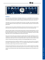
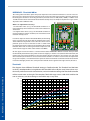
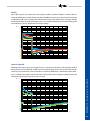
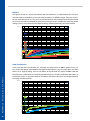
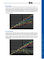
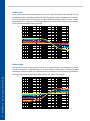
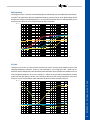
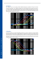
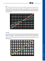
A COMPRE
SS
OR
H
PH
OMPRESS O
C
A
R
AL
AL
P
The information in this document is subject to
change without notice and shall not be deemed as
a warranty by the manufacturer. No warranties, express or implied, are made with regard to the quality,
suitability or accuracy of this document.
The manufacturer reserves the right to change the
contents of this document and/or the associated
products at any time without the provision of prior
notice. The manufacturer shall not be held liable for
damages of any kind arising from the use, or the inability to use this product or its documentation.
The information in this document is subject to copyright. All rights, technical changes and errata are reserved. No part of this manual may be reproduced or
transmitted in any form or for any purpose without
the explicitly written permission of the copyright
holders.
elysia is a registered trademark of elysia GmbH.
Other product and brand names contained in this
document are used for identification purposes only.
All registered trademarks, product designations or
brand names used in this document are the property
of their respective owners. © 2006 elysia GmbH
Dear friend of audio culture,
First of all, we would like to thank you sincerely for choosing the alpha compressor as your new
mastering tool. From now on, you not only have the maximum possible audio quality in dynamics
processing at your disposal, but also a complete arsenal of flexible and effective tools which will
shift the results of your work to a new level.
In short: You have opted for a product designed without the slightest compromise!
Please take a little time to read this manual thoroughly, as it will help you to entirely understand
the enormous potentials and to really push the envelope. We have attached great importance to
practical experience and fast results, which is also the reason for reserving the explanation of the
technological excesses realized in the alpha compressor to our website.
The “Basics“ chapter contains essential information for the fundamental comprehension and quick
use of the specific functions and modules. After this, a couple of “Scenarios” are introduced in
order to illuminate just some of the versatile applications of your new favorite compressor. If you
want to go into further details, please have a look at the “Reference” chapter which elaborates on
every particular parameter.
If you have further questions or comments, please do not hesitate to contact us – we enjoy being
of your service. But for now, it’s time to wish you lots of fun and pure audio pleasure with your
alpha compressor.
Use the Force…
the elysians
Mounting
The best way to place the alpha compressor is to put it on top of a rack. In this position, ventilation will be
optimal and the unit will not heat up too much.
In case you mount it into a 19“ rack or vertically into a console, please leave a free space of about 2cm on top
and bottom so that the air can circulate freely. Also make sure that the rack rails can really carry the heavy
weight: the device weighs about 16kg that should be reinforced from the back in case of doubt. If required,
the four aluminum stands can be unscrewed from the outside of the housing.
Dependent on your personal studio ambience, you might find the light intensity of the controllers and buttons too bright or too dark. This is no problem, because two separate wheel controllers on the back panel
help you to adapt the lights to your particular needs.
Audio Path
Definitely no secret, but still worth mentioning: Inferior cables can noticeably decrease the entire audio
quality; therefore no compromises should be made in this regard. All audio cables should be of a high quality and as short as possible.
Furthermore, only the processors that are needed every day should be constant parts of the signal chain.
Not all compressors, equalizers etc. feature real hard bypasses; resulting in irretrievable losses of sonic details. The motto ‚less is more‘ is pretty obvious in this case.
Note: If a noticeable change in level occurs when the compressor is activated, balanced connection might
be the reason. Please look at page 36 for further information.
Warm Up
When the compressor is powered up, it might happen that the Gain reduction meters fully light up even
when there is no audio signal present (depending on the operation mode and the setting of parameters,
both meters might even display different values). After a warm up time of about 15 minutes this will be gone
automatically.
All temperature-sensitive circuits will be heated up by then and the compressor is ready for operation. Only
now constant control characteristics and best possible audio quality can be achieved, therefore the warmup time must be adhered to before every production.
Safety Instructions
Voltage:
Please check if the voltage needed in your country is set correctly at the back side of the unit
before powering it up.
Service:
Make sure to have your unit serviced by authorized personnel only and contact elysia for technical support. Please open the alpha compressor only in case you really know what has to be
EX ANTE
done.
Environment:Avoid heat, cold, humidity, vibrations, dust and electronic (e.g. transformers) as well as digital
(digital processors) stray fields.
Cleaning: Clean the unit with a dry, clean cloth. Never use chemical dissolvers or cleansers!
BASICS
6
Basic Design. . . . . . . . . . . . . . . . . . . . . . . . . . . . . . . . . . . . . . . . . . . . . . . . . . . . . . . . . . . 6
Stereo Compression . . . . . . . . . . . . . . . . . . . . . . . . . . . . . . . . . . . . . . . . . . . . . . . . . . . . . 8
Auto Fast . . . . . . . . . . . . . . . . . . . . . . . . . . . . . . . . . . . . . . . . . . . . . . . . . . . . . . . . . . . . . 9
Feed Forward . . . . . . . . . . . . . . . . . . . . . . . . . . . . . . . . . . . . . . . . . . . . . . . . . . . . . . . . . 10
Transformer . . . . . . . . . . . . . . . . . . . . . . . . . . . . . . . . . . . . . . . . . . . . . . . . . . . . . . . . . . 10
MS Matrix . . . . . . . . . . . . . . . . . . . . . . . . . . . . . . . . . . . . . . . . . . . . . . . . . . . . . . . . . . . 11
Sidechain Filter . . . . . . . . . . . . . . . . . . . . . . . . . . . . . . . . . . . . . . . . . . . . . . . . . . . . . . . . 12
Audio Filter . . . . . . . . . . . . . . . . . . . . . . . . . . . . . . . . . . . . . . . . . . . . . . . . . . . . . . . . . . 13
Mix Controller . . . . . . . . . . . . . . . . . . . . . . . . . . . . . . . . . . . . . . . . . . . . . . . . . . . . . . . . 14
Soft Clip Limiter . . . . . . . . . . . . . . . . . . . . . . . . . . . . . . . . . . . . . . . . . . . . . . . . . . . . . . . 15
SCENARIOS
. . . . . . . . . . . . . . . . . . . . . . . . . . . . . . . . . . . . . . . . . . . . . . . 16
Stereo Linked . . . . . . . . . . . . . . . . . . . . . . . . . . . . . . . . . . . . . . . . . . . . . . . . . . . . . . . . . 16
MS Linked . . . . . . . . . . . . . . . . . . . . . . . . . . . . . . . . . . . . . . . . . . . . . . . . . . . . . . . . . . . 17
MS Unlinked. . . . . . . . . . . . . . . . . . . . . . . . . . . . . . . . . . . . . . . . . . . . . . . . . . . . . . . . . . 18
Upward Leveling . . . . . . . . . . . . . . . . . . . . . . . . . . . . . . . . . . . . . . . . . . . . . . . . . . . . . . 19
MS Leveling . . . . . . . . . . . . . . . . . . . . . . . . . . . . . . . . . . . . . . . . . . . . . . . . . . . . . . . . . . 20
Groove Compression . . . . . . . . . . . . . . . . . . . . . . . . . . . . . . . . . . . . . . . . . . . 21
Vocal Down . . . . . . . . . . . . . . . . . . . . . . . . . . . . . . . . . . . . . . . . . . . . . . . . . . . . . . . . . . 22
DeEssing . . . . . . . . . . . . . . . . . . . . . . . . . . . . . . . . . . . . . . . . . . . . . . . . . . . . . . . . . . . . 23
Parallel Compression . . . . . . . . . . . . . . . . . . . . . . . . . . . . . . . . . . . . . . . . . . . . . . . . . . . . 24
Stereo Enhancer . . . . . . . . . . . . . . . . . . . . . . . . . . . . . . . . . . . . . . . . . . . . . . . . . . . . . . . 25
LoFi Compression . . . . . . . . . . . . . . . . . . . . . . . . . . . . . . . . . . . . . . . . . . . . . . . . . . . . . . 26
Extreme Settings . . . . . . . . . . . . . . . . . . . . . . . . . . . . . . . . . . . . . . . . . . . . . . . . . . . . . . . 27
REFERENCE . . . . . . . . . . . . . . . . . . . . . . . . . . . . . . . . . . . . . . . . . 28
Threshold Offset . . . . . . . . . . . . . . . . . . . . . . . . . . . . . . . . . . . . . . . . . . . . . . . . . . . . . . . 28
Threshold . . . . . . . . . . . . . . . . . . . . . . . . . . . . . . . . . . . . . . . . . . . . . . . . . . . . . . . . . . . 28
Attack . . . . . . . . . . . . . . . . . . . . . . . . . . . . . . . . . . . . . . . . . . . . . . . . . . . . . . . . . . . . . 29
Auto Fast Attack . . . . . . . . . . . . . . . . . . . . . . . . . . . . . . . . . . . . . . . . . . . . . . . . . . . . . . . 29
Release . . . . . . . . . . . . . . . . . . . . . . . . . . . . . . . . . . . . . . . . . . . . . . . . . . . . . . . . . . . . . 30
Auto Fast Release . . . . . . . . . . . . . . . . . . . . . . . . . . . . . . . . . . . . . . . . . . . . . . . . . . . . . . 30
Ratio Feedback . . . . . . . . . . . . . . . . . . . . . . . . . . . . . . . . . . . . . . . . . . . . . . . . . . . . . . . . 31
Ratio Feed Forward . . . . . . . . . . . . . . . . . . . . . . . . . . . . . . . . . . . . . . . . . . . . . . . . . . . . . 31
EQ Gain Low . . . . . . . . . . . . . . . . . . . . . . . . . . . . . . . . . . . . . . . . . . . . . . . . . . . . . . . . . 32
EQ Gain High . . . . . . . . . . . . . . . . . . . . . . . . . . . . . . . . . . . . . . . . . . . . . . . . . . . . . . . . 32
EQ Frequency . . . . . . . . . . . . . . . . . . . . . . . . . . . . . . . . . . . . . . . . . . . . . . . . . . . . . . . . 33
SC Gain . . . . . . . . . . . . . . . . . . . . . . . . . . . . . . . . . . . . . . . . . . . . . . . . . . . . . . . . . 33
SC Low Pass . . . . . . . . . . . . . . . . . . . . . . . . . . . . . . . . . . . . . . . . . . . . . . . . . . . . . . . . . 34
SC High Pass . . . . . . . . . . . . . . . . . . . . . . . . . . . . . . . . . . . . . . . . . . . . . . . . . . . . . . . . . 34
Mix . . . . . . . . . . . . . . . . . . . . . . . . . . . . . . . . . . . . . . . . . . . . . . . . . . . . . . . . . . . . . . . 35
Soft Clip . . . . . . . . . . . . . . . . . . . . . . . . . . . . . . . . . . . . . . . . . . . . . . . . . . . . . . . . . . . . 35
Level Problems . . . . . . . . . . . . . . . . . . . . . . . . . . . . . . . . . . . . . . . . . . . . . . . . . . . . . . 36
Technical Data . . . . . . . . . . . . . . . . . . . . . . . . . . . . . . . . . . . . . . . . . . . . . . . . . . . . . . . . 37
Warranty . . . . . . . . . . . . . . . . . . . . . . . . . . . . . . . . . . . . . . . . . . . . . . . . . . . . . . . 38
Recall Sheet . . . . . . . . . . . . . . . . . . . . . . . . . . . . . . . . . . . . . . . . . . . . . . . . . . . . . . . . . 39
INDEX
APPENDIX . . . . . . . . . . . . . . . . . . . . . . . . . . . . . . . . . . 36
BASICS - Basic Design
Never fear! With its many options and quite a lot of controllers the alpha compressor might look a
little tricky at first sight. In practical experience, however, it is a clearly structured and easy to use
tool.
The control elements are divided into three layers, whereas the left and the right channel sides are
completely identical.
+4
Thresh
0
+11
-6
+15
70
2,0
Feed Forward
800
75
Auto Fast
1,9
2,1
1,2
1k8
ms
1,8
1,3
1k5
60
1,7
1,4
1k1
150
ms
1,6
Ratio
570
100
130
0,01
430
150
110
-13
dB
300
Release
50
7,0
-12
+20
28
13
-9
+18
24
Attack
-3
2,2
1,1
2,4
1:X
Auto Fast
Compressor section
The upper array contains the dynamic section with the classic parameters Threshold, Attack, Release and Ratio. Furthermore, there are some interesting special functions like Feed Forward and
Auto Fast that will be explained later.
0,3
0,3
EQ Gain
1,0
1,6
1,6
2,2
dB
-0,3
220
Hi
Hz
2k0
dB
430
580
50
900
40
-12
LP
x10
340
80
-5
-12
280
SC Freq
-2
-5
1k0
20
On
SC Gain
-2
500
22
-0,3
-1
300
30
2,7
Lo
170
40
2,2
2,7
140
EQ Freq
HP
2k0
30
On
Hz
3k3
Filter section
Firstly, the middle array features the Audio filter, which enables you to perform subtle changes
on the overall tonal character. Secondly, it consists of the Sidechain filter which allows frequencydependent compression when it is switched into the detector path.
50
Mix
60
30
80
BASICS - Basic Design
20
90
10
Direct
%
4,5
Com
2,0
8,0
1,5
10
dB
16
14
11
19
8,0
21
5,5
24
11
0
Compressed
Soft Clip
6,0
0,5
100
Dir
3,5
Gain
70
12
4,0
25
Transformer
dB
3,0
On
Level section
The lower array starts with the Mix controller that allows blending between the unprocessed and
the compressed, filtered and amplified signals. Next in line is the Gain controller to make up the
gain of the reduced signal. The last one is the Soft Clip limiter which allows catching fast transients.
In the middle of the unit, right below the Gain reduction meters, there are three buttons to set the
distinct operating modes of the alpha compressor:
Active
If this button is pressed (LED glows), the incoming signals will be processed in the alpha compressor. Otherwise there will be a hard bypass, whereas the Gain reduction meters will still stay
active.
MS Mode
If this button is pressed, the alpha compressor will work in MS mode in which the controls on the
left side affect the middle channel and those on the right side belong to the side channel. Otherwise the unit will work in Stereo mode. The Soft Clip limiter will not be influenced by this setting
as it always works in Stereo mode.
Channel Link
If this button is pressed, the left upper array will act as a master for the dynamic sections of both
channels. All other parameters (Filter, Mix, Gain etc.) will not be linked, though, and therefore have
to be set manually. In this mode the Gain reduction will be identical for both channels.
Block Diagram
The schematic shows the signal flow from the input through the specific modules to the output.
MS matrix, Sidechain filters, Audio filters, Mix stages, Transformers and Soft Clip limiters can be
optionally switched into the signal path via relays, which can also be done with the Auto Fast and
Feed Forward functions.
Sidechain
Filter
Transformer
Soft Clip
Limiter
Input
Transformer
Sidechain
Gainreduction
Meter
Mix
Stage
Output
Amp
Input
Buffer
Compressor
Audio
Filter
Gain
Stage
Left
Output
Input
Buffer
Compressor
Audio
Filter
Gain
Stage
Right
Output
Input
Transformer
Sidechain
Gainreduction
Meter
Mix
Stage
Output
Amp
Right
Input
Sidechain
Filter
Transformer
Soft Clip
Limiter
BASICS - Basic Design
MS Encoder
MS Decoder
Left
Input
Thresh
Attack
Release
Feed Forward
Ratio
Auto Fast
On
Attack
x10
Gain
dB
ms
Auto Fast
Ratio
ms
EQ Gain EQ Freq
SC Gain SC Freq
Hz
Release
Feed Forward
Auto Fast
EQ Gain EQ Freq
Mix
Thresh
Soft Clip
On
On
Mix
Soft Clip
Auto Fast
1:X
SC Gain SC Freq
x10
dB
On
Soft Clip
Gain
Gain Reduction
Direct
Compressed
Transformer
On
MS Mode
Active
Channel Link
Direct
Compressed
Transformer
On
Stereo Compression
In order to get a first impression of the sonic quality and the control characteristics of the alpha
compressor, only the controllers highlighted in the figure will be engaged. The functions that are
currently not needed should be deactivated (related LEDs do not glow). Et voilà: We have a classic
linked stereo compressor!
A track with a broad dynamic range is the best material for a first test. Just start playing with the
Threshold, Attack, Release and Ratio parameters of the left channel in order to get to know the
control behavior of the compressor. Allow yourself to take some time for this, as the understanding of the basic control characteristics is the most important condition for perfect results.
Keep having a look at the Gain reduction meters from time to time. No doubt: the ear is the decisive benchmark. Just consider the optical information as a supporting means to evaluate the
control mode (fast/slow, strong/weak, etc.).
The level of the compressed signals can be made up by adding an appropriate amount of amplification with the Gain controllers. Since the Link function will only affect the control mode of the
compressor, the Gain controllers of both channels should be set to the same values in Stereo Link
mode. For instant AB comparisons just push the Active button.
BASICS - Stereo Compression
Note: If the Threshold controller produces too little Gain reduction when turned hard right or too
much of it when turned hard left, please go to page 28 and see how to adjust the internal Threshold.
Left
Input
Compressor
Gain
Stage
Transformer
Left
Output
Gain
Stage
Transformer
Right
Output
Sidechain
Right
Input
Compressor
Auto Fast (Attack)
The Auto Fast function causes an automatic shortening of the control time on fast and loud signal
peaks. This effect is easy to comprehend when compressing a preferably dynamic drum loop, for
example.
Please set the following values as a starting position:
•
•
•
•
Attack:
Release:
Ratio:
Threshold: 50ms
300ms
1:1,8
Set to a position that results in approx. 3-4dB Gain reduction
Because of the quite long Attack time the snare and bass drum will be processed very moderately.
If Auto Fast is now engaged, the compressor will react to the fast and loud peaks, resulting in a
noticeably higher amount of Gain reduction.
And here is the trick: Directly after this process the Attack time will return to the value that was
originally set, and on ‚slower‘ signals the original value will not be changed at all. The compressor
will only become very fast in case it is really needed!
Auto Fast (Release)
The same example is also suitable to use the Auto Fast function for the Release parameter, too.
The following values are useful to get started:
•
•
•
•
Attack:
Release:
Ratio:
Threshold:
30ms + Auto Fast
300ms
1:1,8
Set to a position that results in approx. 7-8dB Gain reduction
Now press the Auto Fast button of the Release controller and keep your ears open as well as an eye
on the meter: the area between 4-8dB is reduced very fast now, whereas the set value of 300ms
stays valid between 0 and 4dB.
This function can be a great help especially for applications with difficult dynamic structures, as it
counteracts the danger of clippings caused by too short values and the loss of loudness and pressure caused by too slow settings at the same time.
BASICS - Auto Fast
Note: If you use very long Release times, the effectiveness of this function will decrease. Very long
Attack times will also reduce the intensity of this circuit.
Feed Forward
This function makes it possible to switch the junction of the Sidechain alternatively behind (Feedback) or in front (Feed Forward) of the actual compressor section. This has an enormous effect on
the character of the compressor.
Again, our drum loop can be used for demonstration: While processing in Feedback mode will run
very smooth and even, switching into Feed Forward mode will result in a clearly more aggressive
and harder kind of compression.
From the technical point of view this function mainly influences the characteristic curve of the
Ratio value. In Feedback mode it goes up to a moderate Ratio of 1:2,5. In contrast, the Feed Forward mode provides much higher values that also allow limiter settings and even negative ratios
(i.e. loud signals will be reduced even more). Thus, small changes in dynamics can generate a high
amount of Gain reduction.
The values of the Attack controller will also change noticeably in Feed Forward mode, as they will
become almost twice as high as the value shown on the scale.
Transformer
Each of the two channels features an additional transformer that can be switched into the signal
chain after the Mix stage. In principle, these are classic output transformers, but here they are not
used for balancing and galvanic isolation, but as an additional means of sound design.
10
In Stereo mode the buttons for both channels should be activated or deactivated at the same
time. Depending on the source material and personal taste, you can, however, also add the transformer sound to single channels when working in MS mode.
Right
Input
M
Compressor
Sidechain
S
Compressor
Gain
Stage
L
Left
Output
MS Decoder
Left
Input
MS Encoder
BASICS - Feed Forward & Transformer
If you like to add that certain amount of ‚iron‘ to your sound, just push the Transformer button and
there you are. Because of the mastering approach of the alpha compressor this feature is much
more a subtle audio shaping feature than a glaring sound effect.
Sidechain
Gain
Stage
R
Right
Output
Thresh
Attack
Release
Feed Forward
Ratio
Auto Fast
On
Attack
x10
Gain
dB
ms
Auto Fast
Ratio
ms
EQ Gain EQ Freq
SC Gain SC Freq
Hz
Release
Feed Forward
Auto Fast
EQ Gain EQ Freq
Mix
Thresh
Soft Clip
On
On
Mix
Soft Clip
Auto Fast
1:X
SC Gain SC Freq
x10
Gain
dB
On
Soft Clip
Gain Reduction
Direct
Compressed
Transformer
On
MS Mode
Active
Channel Link
Direct
Compressed
Transformer
On
MS Matrix
One of the most powerful features of the alpha compressor is its switchable MS matrix. By activating it, the incoming stereo signal is encoded into a middle channel (mono) and a side channel
which contains the stereo parts of the left and right channel (but not the common mono part).
This enables you to process the middle and the side signals separately, and finally both channels
will be decoded back to left and right (stereo). A practical example easily helps to understand the
general idea.
The ideal song for this would be the following: Important tracks like voice, drums and bass have
been placed in the middle whereas the remaining instruments are mixed stereophonically.
Switch the alpha compressor into MS mode and leave the Link function deactivated for now. The
left side of the compressor now controls the middle channel and the right side the side channel.
By using the Compressed switches, you can listen to both channels separately, so that you will be
able to hear what is instantly happening in the particular channel.
Now you can process the mono and side parts separately from each other. Depending on the mix,
sometimes it is only the middle channel that needs compression whereas the side channel stays
unprocessed. Other mixes have a lot of stereo information; in these cases both middle and side
channels are processed, the settings of which can be completely different from each other.
Of course the Link function also works in MS mode. In this case, signals in the M and S channels
are reduced evenly so that the result of the compression is the same as if working in stereo mode.
However, you will still be able to adjust the level proportion between M and S with the Gain controllers.
BASICS - MS Matrix
At the beginning, both Gain controllers should be set at the same values, but that can change in
the progress of optimization by all means. You can use different settings of the Gain controllers in
MS mode for specific changes of the stereo width, for example.
11
Thresh
Attack
Release
Feed Forward
Ratio
Auto Fast
Attack
x10
Hz
Gain
ms
Auto Fast
Mix
Soft Clip
Auto Fast
1:X
SC Gain SC Freq
On
On
dB
ms
Ratio
EQ Gain EQ Freq
SC Gain SC Freq
Mix
Release
Feed Forward
Auto Fast
EQ Gain EQ Freq
On
Thresh
Soft Clip
x10
dB
On
Soft Clip
Gain
Gain Reduction
Direct
Compressed
Transformer
On
MS Mode
Active
Channel Link
Direct
Compressed
Transformer
On
Sidechain Filter
The Sidechain filter allows frequency-dependent shaping of the compression by giving specific
frequency areas a stronger or weaker influence on the detection circuit.
The linked MS mode is most suitable to demonstrate the effect: Since most signal energy can be
found in the middle as a general rule (bass drum etc.), the filter will have its greatest impact here.
A track with a balanced proportion of bass, middle and treble frequencies should be chosen to
give this function a try.
If the SC Gain controller is set to HP (High Pass), the filter will act like a 6dB high pass and the
reaction of the compressor on bass frequencies decreases. The setting LP (Low Pass) turns the
filter into a 6dB low pass and the compressor reacts primarily on low frequencies. Again, the Gain
reduction meter is a reliable aid to evaluate the distinct modes of operation.
The combination of Sidechain filters, MS matrix and different Attack settings enables you to make
very selective changes and – depending on the source material – even to process single instruments or voices in finished mixes. Details on that can be found in the “Scenarios” chapter.
12
M
Right
Input
S
Gain
Stage
Compressor
Sidechain
Filter
Sidechain
Compressor
L
Left
Output
MS Decoder
Left
Input
MS Encoder
BASICS - Sidechain Filter
Note: When working in linked Stereo mode, the Sidechain filters of both channels should be set
to identical values. In linked MS mode, however, only the Sidechain filter of the middle channel is
active, and in unlinked MS mode the SC filter of the side channel is available, too.
Gain
Stage
R
Right
Output
Thresh
Attack
Release
Feed Forward
Ratio
Auto Fast
On
Attack
x10
Gain
dB
ms
Ratio
ms
Auto Fast
EQ Gain EQ Freq
SC Gain SC Freq
Hz
Release
Feed Forward
Auto Fast
EQ Gain EQ Freq
Mix
Thresh
Soft Clip
On
On
x10
Mix
Soft Clip
Auto Fast
1:X
SC Gain SC Freq
dB
On
Soft Clip
Gain
Gain Reduction
Direct
Compressed
Transformer
On
MS Mode
Active
Channel Link
Direct
Compressed
Transformer
On
Audio Filter
The Audio filter is placed behind the compressor, avoiding unwanted influences on the detection
circuit of the dynamic section.
If the EQ Gain controller is turned hard right, the signal rates above the selected center frequency
will be boosted by 3dB and the part below the center frequency will be cut by 5dB [Fig. A]. Turning
the controller hard left reverses the effect: Below the center frequency there is a boost and above
it there is a cut [Fig. B].
B
A
+
+
Gain
Gain
-
Center Frequency
Center Frequency
The EQ Freq controller comprehends an array from 20Hz - 2kHz which can be shifted to 200Hz
- 20kHz by pushing the x10 button.
In the linked MS mode shown above it is possible to make different settings for the Audio filters
in the M and the S band. Again, the results can be listened to separately by using the Compressed
switches for each channel. However, in Stereo mode, both Audio filters should be set to the same
values in order to avoid unwanted shifts in the stereo spectrum.
Compressor
Right
Input
S
Audio
Filter
Gain
Stage
Audio
Filter
Gain
Stage
Sidechain
Compressor
L
Left
Output
MS Decoder
M
MS Encoder
Left
Input
R
Right
Output
BASICS - Audio Filter
Note: Depending on the settings of the Audio filters it might be necessary to adapt the volume
with the Gain controllers.
13
Thresh
Attack
Release
Feed Forward
Ratio
Auto Fast
On
Attack
x10
Gain
dB
ms
Auto Fast
Ratio
ms
EQ Gain EQ Freq
SC Gain SC Freq
Hz
Release
Feed Forward
Auto Fast
EQ Gain EQ Freq
Mix
Thresh
Soft Clip
On
On
x10
Mix
Soft Clip
Auto Fast
1:X
SC Gain SC Freq
Gain
dB
On
Soft Clip
Gain Reduction
Direct
Compressed
Transformer
On
MS Mode
Active
Channel Link
Direct
Compressed
Transformer
On
Mix Controller
The Mix controller makes it possible to cross-fade between the unprocessed and the compressed/
filtered signals. This allows parallel compression right in the alpha compressor; and renders additional routings in favor of a better signal quality unnecessary.
Now you can use even extreme compression settings without killing the track by winning the
loudness war. By mixing just a part of the compressed signal to the original one the major portion
of the initial dynamic structure remains.
The control logic of this feature is also worth mentioning. If only the Compressed button is pushed,
you will hear the compressed signal only. Otherwise, if only the Direct button is pushed, only the
unprocessed signal routed from before the compressor section will be audible. If both buttons are
pushed, the Mix controller will become active, and if none of the buttons is pushed, the channel
will be muted.
In practice you can switch between unprocessed, compressed or mixed signals very fast without
having to change the position of the Mix controller.
14
Mix
Stage
M
Right
Input
S
Left
Output
Gain
Stage
Compressor
Sidechain
Compressor
L
MS Decoder
Left
Input
MS Encoder
BASICS - Mix Controller
In this way, the left and right channels (Stereo mode) respectively the middle and side channels
(MS mode) can be listened to separately – here you have the choice again between the original,
the compressed or the mixed signal. To mute the other channel, just deactivate the associated
Direct and Compressed buttons.
Gain
Stage
Mix
Stage
R
Right
Output
Thresh
Attack
Release
Feed Forward
Ratio
Auto Fast
Attack
x10
Hz
Gain
dB
ms
Ratio
ms
Auto Fast
EQ Gain EQ Freq
SC Gain SC Freq
Mix
Release
Feed Forward
Auto Fast
EQ Gain EQ Freq
On
Thresh
Soft Clip
On
On
Mix
Soft Clip
Auto Fast
1:X
SC Gain SC Freq
x10
dB
On
Soft Clip
Gain
Gain Reduction
Direct
Compressed
Transformer
On
MS Mode
Active
Channel Link
Direct
Compressed
Transformer
On
Soft Clip Limiter
The Soft Clipper was designed to limit short, loud transients, and thus protecting subsequent AD
converters from clipping. However, the circuit does not behave like a classic brick wall limiter, but
more like an analog tape machine driven into saturation: it rounds the peaks instead of making
hard cuts.
The Soft Clip modules are placed directly in front of the output stages. Their settings are not influenced by the Mix and Gain controllers. This is also the case in MS mode, because the limiters are
located after the MS decoder and therefore are always assigned to the left and right stereo channels. Note that the channel link does not affect the circuit either – because of this the settings of
the Soft Clip controllers for both channels should always be identical!
If the alpha compressor is the last unit in the signal path before the AD converter, it is only once
that the setting of the Soft Clip limiter has to be adapted to the converter. The best would be to
use a fast, sample-accurate PPM meter to find the right setting, because it is an accurate method
of benchmarking the resulting decrease in level.
Left
Input
Soft Clip
Limiter
Left
Output
Right
Input
Soft Clip
Limiter
Right
Output
BASICS - Soft Clip Limiter
The Soft Clip LEDs located on top of the Gain reduction meters should only light up shortly, as
noticeable distortion appears if you drive this circuit too hard. Particularly with regard to acoustic
and classical music, this feature should be used with care and moderate settings only.
15
16
dB
dB
Feed Forward
Lo
Hi
Direct
10
%
Com
Hz
0,5
1,5
2,0
Gain
2k0
0
1k0
3,5
500
300
220
12
HP
-12
24
21
19
25
-5
-2
Soft Clip
dB
Auto Fast
1,2
1,3
1,4
1,1
Ratio
16
dB
14
On
3,0
1,7
5,5
8,0
On
Hz
5,0
6,0
2k0 11
9,5
8,5
4307,5
2,4
12
4,0
2,1
1,9
2,2
1,8
3k3
1:X
280 340
1,6
30
4,0
11
40
50
80
SC Gain SC Freq
1k5
1k1
800
570
1k8
Transformer
10
8,0
11
6,0
430
ms
-0,3 -0,3
LP
-1
60
300
14
3,0
18
20
MS Mode
16
2,0
1,5
1,0
Soft Clip
If necessary, you can use the Mix controllers to apply the effect of the
compressor in even finer doses (both Direct and Compressed buttons
have to be activated for this).
In order to come up to such styles of music you should make sure to
create an unobtrusive and smooth kind of compression. This can be
achieved by setting a long Attack time and a Ratio value in the lower control range, at which only a very few dB of Gain reduction are required.
Active
18
1,5
16
2,0
14
3,0
Channel Link
20
1,0
12
4,0
11
Lo
1,0
+20
2,7
9,5
8,5
7,5
6,0
5,0
+18
+15
+11
Thresh
dB
dB
-3
Hi
10
Dir
50
%
60
On
Com
90
Hz
0,5
1,5
2,0
Gain
2k0
0
1k0
3,5
500
300
220
dB
4,5
x10
12
19
24
21
Transformer
11
10
8,0
-12
25
-5
-2
Soft Clip
dB
Auto Fast
1,2
1,3
1,4
1,1
Ratio
16
dB
14
On
3,0
1,7
5,5
8,0
On
Hz
2k0
800
500
430
2,4
2,1
1,9
2,2
1,8
3k3
1:X
280 340
1,6
30
4,0
11
40
50
80
SC Gain SC Freq
1k8
1k5
1k1
800
570
HP
430
ms
-0,3 -0,3
300
LP
-1
60
6,0
-12
-5
-2
75
100
150
Release
Auto Fast
110
70
130
50
150
Compressed
100
28
ms
140 170
24
80
20
70
22
30
2,2
2,7
40
1,6
Mix
20
0,01
2,0
7,0
13
Feed Forward
-12
-9
-6
Attack
EQ Gain EQ Freq
-13
30
0,3
0
Direct
0,3
+4
Of course the linked Stereo mode can also be used for many other styles
of music, but often you’ll be able to achieve even better results in MS
mode.
Note: Look after setting the Mix, Gain and Filter controllers at the same
values when working in Stereo mode. The Link function only affects the
control mode of the actual compressor section.
Moreover, you can kick in the Audio filters to make additional sonic corrections.
Gain Reduction
This setting is especially useful for tracks in which the instruments are
not placed straight in the middle of the stereo spectrum – when a recording has been made with the use of classic stereo miking like in Jazz,
for example.
dB
4,5
x10
-12
-5
-2
75
100
150
Release
Auto Fast
110
70
130
50
150
Compressed
100
90
Dir
20
70
20
60
On
80
50
22
30
Mix
2,7
30
40
28
ms
140 170
24
SCENARIOS - Stereo Linked
2,7
0,01
2,0
7,0
13
Attack
EQ Gain EQ Freq
-13
2,2
0,3
2,2
0,3
1,6
1,0
+20
-12
1,6
+18
-9
-3
+15
0
-6
+4
+11
Thresh
SCENARIOS - Stereo Linked
17
dB
dB
Feed Forward
Lo
Hi
%
Com
2k0
0,5
1,5
2,0
Gain
Compressed
100
Hz
0
1k0
3,5
500
dB
4,5
x10
12
24
21
19
Transformer
11
10
8,0
-12
25
-5
-2
Soft Clip
dB
Auto Fast
1,2
1,3
1,4
1,1
Ratio
16
dB
14
On
3,0
1,7
5,5
8,0
On
Hz
5,0
6,0
2k0 11
9,5
8,5
4307,5
2,4
12
4,0
2,1
1,9
2,2
1,8
3k3
1:X
280 340
1,6
30
4,0
11
40
50
80
SC Gain SC Freq
1k8
1k5
1k1
800
570
HP
430
ms
-0,3 -0,3
300
LP
-1
60
6,0
-12
-5
-2
75
100
150
Release
Auto Fast
300
220
150
110
70
130
50
14
3,0
18
20
MS Mode
16
2,0
1,5
1,0
Variations of the Release time are especially effective in controlling the
attained amount of loudness. Here, activating the Auto Fast function
should be preferred to setting a very fast Release time.
The figured settings are a good starting position for many pop and rock
tracks: the Attack time of 30-40ms ensures that transients from percussion instruments will hardly be compressed, while the Release time of
250ms lets the compressor decrease its Gain reduction fast enough.
SCENARIOS - MS Linked
Soft Clip
Active
18
1,5
16
2,0
14
3,0
Channel Link
20
1,0
12
4,0
11
Lo
1,0
+20
2,7
9,5
8,5
7,5
6,0
5,0
+18
+15
+11
Thresh
dB
dB
-3
Hi
10
Dir
50
%
60
On
Com
90
Hz
0,5
1,5
2,0
Gain
2k0
0
1k0
3,5
500
300
220
dB
4,5
x10
12
24
21
19
Transformer
11
10
8,0
-12
25
-5
-2
Soft Clip
dB
Auto Fast
1,2
1,3
1,4
1,1
Ratio
16
dB
14
On
3,0
1,7
5,5
8,0
On
Hz
2k0
800
500
430
2,4
2,1
1,9
2,2
1,8
3k3
1:X
280 340
1,6
30
4,0
11
40
50
80
SC Gain SC Freq
1k8
1k5
1k1
800
570
HP
430
ms
-0,3 -0,3
300
LP
-1
60
6,0
-12
-5
-2
75
100
150
Release
Auto Fast
110
70
130
50
150
Compressed
100
28
ms
140 170
24
80
20
70
22
30
2,2
2,7
40
1,6
Mix
20
0,01
2,0
7,0
13
Feed Forward
-12
-9
-6
Attack
EQ Gain EQ Freq
-13
30
0,3
0
Direct
0,3
+4
But what is the essential advantage of the linked MS mode compared
to the linked Stereo mode? The levels of M and S can be set differently,
which makes it very easy to perform changes of the stereo width (Mix
too narrow? More gain to the side channel. Not enough punch? Add
gain to the middle). Furthermore, a left/right drift caused by possible
unequal settings of the Gain controllers is impossible in this mode.
The generated Gain reduction is primarily affected by matching the
Threshold and Ratio parameters. A Ratio of 1:1,7 has often proved to be
a good start.
Gain Reduction
The function of the compressor in linked MS mode is quite similar to its
function in linked Stereo mode. The time parameters are set with the
controllers on the left side of the unit, and the resulting Gain reduction
in the middle and the side channel will be exactly the same.
10
Dir
70
20
90
60
On
20
50
22
80
Mix
2,7
30
40
28
ms
140 170
24
30
Direct
MS Linked
2,7
0,01
2,0
7,0
13
Attack
EQ Gain EQ Freq
-13
2,2
0,3
2,2
0,3
1,6
1,0
+20
-12
1,6
+18
-9
-3
+15
0
-6
+4
+11
Thresh
18
dB
dB
Feed Forward
Lo
Hi
2,7
Direct
%
2k0
dB
4,5
x10
12
dB
HP
-12
24
21
19
25
-5
-2
Soft Clip
Transformer
11
10
8,0
LP
6,0
Auto Fast
1,2
1,3
1,4
1,1
Ratio
16
dB
14
On
3,0
1,7
5,5
8,0
On
Hz
5,0
6,0
2k0 11
9,5
8,5
4307,5
2,4
12
4,0
2,1
1,9
2,2
1,8
3k3
1:X
280 340
1,6
30
4,0
11
40
50
80
SC Gain SC Freq
1k8
1k5
1k1
800
570
14
3,0
18
20
MS Mode
16
2,0
1,5
1,0
Active
Gain Reduction
Soft Clip
18
1,5
16
2,0
14
3,0
Channel Link
20
1,0
12
4,0
11
Lo
1,0
+20
2,7
9,5
8,5
7,5
6,0
5,0
+18
+15
+11
Thresh
dB
dB
-3
Hi
10
Dir
50
%
60
On
Com
90
Hz
0,5
1,5
2,0
Gain
2k0
0
1k0
3,5
500
300
220
dB
4,5
x10
12
19
24
21
Transformer
11
10
8,0
-12
25
-5
-2
Soft Clip
dB
Auto Fast
1,2
1,3
1,4
1,1
Ratio
16
dB
14
On
3,0
1,7
5,5
8,0
On
Hz
2k0
800
500
430
2,4
2,1
1,9
2,2
1,8
3k3
1:X
280 340
1,6
30
4,0
11
40
50
80
SC Gain SC Freq
1k8
1k5
1k1
800
570
HP
430
ms
-0,3 -0,3
300
LP
-1
60
6,0
-12
-5
-2
75
100
150
Release
Auto Fast
110
70
130
50
150
Compressed
100
28
ms
140 170
24
80
20
70
22
30
2,2
2,7
40
1,6
Mix
20
0,01
2,0
7,0
13
Feed Forward
-12
-9
-6
Attack
EQ Gain EQ Freq
-13
30
0,3
0
Direct
0,3
+4
Thus it can make perfect sense to set strongly differing values of Threshold, Attack, Release and Ratio for the middle and the sides. In order to
achieve a better evaluation of the results, it is advisable to listen to the
processed channel solo for a start.
Once you have discovered the potentials of the MS mode, lots of formerly difficult mixes can be controlled much better, resulting in audibly
better effects.
Using the Audio filters, which can also be set completely different from
each other now, can help to additionally enhance the tonal balance of
a mix.
0
3,5
ms
-0,3 -0,3
430
Depending on the mix and the style of music the dynamics and loudness in the middle and side channel can be completely different from
each other. Take a heavily pumping bass drum right in the middle and
100% stable strings in the sides, for example – just try this with any other
compressor ;-)
Compressed
0,5
1,5
2,0
Gain
-12
-5
-1
60
300
Please remember to deactivate the Direct and Compressed buttons of
the other channel for this.
Com
100
Hz
1k0
500
-2
75
100
150
Release
Auto Fast
300
220
150
110
70
130
50
The true strengths of an MS compressor will not be revealed until it is
switched into unlinked MS mode.
10
90
Dir
20
70
20
60
On
80
50
22
30
40
28
ms
140 170
24
30
Mix
MS Unlinked
2,7
0,01
2,0
7,0
13
Attack
EQ Gain EQ Freq
-13
2,2
0,3
2,2
0,3
1,6
1,0
+20
-12
1,6
+18
-9
-3
+15
0
-6
+4
+11
Thresh
SCENARIOS - MS Unlinked
19
dB
dB
Feed Forward
Lo
Hi
Direct
10
Dir
%
2k0
0,5
1,5
2,0
Gain
Compressed
Hz
0
1k0
3,5
500
dB
4,5
x10
12
24
21
19
Transformer
11
10
8,0
-12
25
-5
-2
Soft Clip
dB
Auto Fast
1,2
1,3
1,4
1,1
Ratio
16
dB
14
On
3,0
1,7
5,5
8,0
On
Hz
5,0
6,0
2k0 11
9,5
8,5
4307,5
2,4
12
4,0
2,1
1,9
2,2
1,8
3k3
1:X
280 340
1,6
30
4,0
11
40
50
80
SC Gain SC Freq
1k8
1k5
1k1
800
570
HP
430
ms
-0,3 -0,3
300
LP
-1
60
6,0
-12
-5
-2
75
100
150
Release
Auto Fast
300
220
150
110
70
130
50
14
3,0
18
20
MS Mode
16
2,0
1,5
1,0
In Feed Forward mode the Attack time is twice as long compared to
Feedback mode and therefore amounts to 300ms. The Ratio characteristic corresponds to the one of a limiter, and the make up gain is about
6dB.
The settings shown above are very suitable for classical music, for example, where ‚typical‘ compression is objectionable. The compressor
works in linked Stereo mode, the Attack time is set at maximum and the
Release time is at 150ms. Under these conditions the alpha compressor
will function as a leveler.
SCENARIOS - Upward Leveling
Soft Clip
Active
18
1,5
16
2,0
14
3,0
Channel Link
20
1,0
12
4,0
11
Lo
1,0
+20
2,7
9,5
8,5
7,5
6,0
5,0
+18
+15
+11
Thresh
dB
dB
-3
Hi
10
Dir
50
%
60
On
Com
90
Hz
0,5
1,5
2,0
Gain
2k0
0
1k0
3,5
500
300
220
dB
4,5
x10
12
24
21
19
Transformer
11
10
8,0
-12
25
-5
-2
Soft Clip
dB
Auto Fast
1,2
1,3
1,4
1,1
Ratio
16
dB
14
On
3,0
1,7
5,5
8,0
On
Hz
2k0
800
500
430
2,4
2,1
1,9
2,2
1,8
3k3
1:X
280 340
1,6
30
4,0
11
40
50
80
SC Gain SC Freq
1k8
1k5
1k1
800
570
HP
430
ms
-0,3 -0,3
300
LP
-1
60
6,0
-12
-5
-2
75
100
150
Release
Auto Fast
110
70
130
50
150
Compressed
100
28
ms
140 170
24
80
20
70
22
30
2,2
2,7
40
1,6
Mix
20
0,01
2,0
7,0
13
Feed Forward
-12
-9
-6
Attack
EQ Gain EQ Freq
-13
30
0,3
0
Direct
0,3
+4
Now the special trick is to set the Mix controller to 50%. By adding the
original signal the initial dynamics will be saved, and the bottom line is
that only the quieter signals will be turned up.
The result of these settings: Quieter passages that do not produce any
Gain reduction will be boosted by 6dB, whereas loud signals will be limited by the compressor.
Gain Reduction
Upward Leveling – this describes the possibility to make only the low
signal parts louder and leave the louder changes in dynamics unprocessed.
Com
100
90
70
20
20
60
On
80
50
22
30
40
28
ms
140 170
24
30
Mix
2,7
Upward Leveling
2,7
0,01
2,0
7,0
13
Attack
EQ Gain EQ Freq
-13
2,2
0,3
2,2
0,3
1,6
1,0
+20
-12
1,6
+18
-9
-3
+15
0
-6
+4
+11
Thresh
20
dB
dB
Feed Forward
Lo
Hi
Direct
%
Com
2k0
0,5
1,5
2,0
Gain
Compressed
100
Hz
0
1k0
3,5
500
dB
4,5
x10
12
24
21
19
Transformer
11
10
8,0
-12
25
-5
-2
Soft Clip
dB
Auto Fast
1,2
1,3
1,4
1,1
Ratio
16
dB
14
On
3,0
1,7
5,5
8,0
On
Hz
5,0
6,0
2k0 11
9,5
8,5
4307,5
2,4
12
4,0
2,1
1,9
2,2
1,8
3k3
1:X
280 340
1,6
30
4,0
11
40
50
80
SC Gain SC Freq
1k8
1k5
1k1
800
570
HP
430
ms
-0,3 -0,3
300
LP
-1
60
6,0
-12
-5
-2
75
100
150
Release
Auto Fast
300
220
150
110
70
130
50
14
3,0
18
20
MS Mode
16
2,0
1,5
1,0
Soft Clip
This method is especially interesting to enhance rock and pop tracks in
a discreet but effective way.
Here the compressor reacts primarily to the complete signal energy
and less to single rhythmic accents. If this principle is now used on the
side and the middle channel separately, a stereo mix will become more
compact in an unobtrusive way and everything will sound a little more
vivid.
Active
18
1,5
16
2,0
14
3,0
Channel Link
20
1,0
12
4,0
11
Lo
1,0
+20
2,7
9,5
8,5
7,5
6,0
5,0
+18
+15
+11
Thresh
dB
dB
-3
Hi
10
Dir
50
%
60
On
Com
90
Hz
0,5
1,5
2,0
Gain
2k0
0
1k0
3,5
500
300
220
dB
4,5
x10
12
19
24
21
Transformer
11
10
8,0
-12
25
-5
-2
Soft Clip
dB
Auto Fast
1,2
1,3
1,4
1,1
Ratio
16
dB
14
On
3,0
1,7
5,5
8,0
On
Hz
2k0
800
500
430
2,4
2,1
1,9
2,2
1,8
3k3
1:X
280 340
1,6
30
4,0
11
40
50
80
SC Gain SC Freq
1k8
1k5
1k1
800
570
HP
430
ms
-0,3 -0,3
300
LP
-1
60
6,0
-12
-5
-2
75
100
150
Release
Auto Fast
110
70
130
50
150
Compressed
100
28
ms
140 170
24
80
20
70
22
30
2,2
2,7
40
1,6
Mix
20
0,01
2,0
7,0
13
Feed Forward
-12
-9
-6
Attack
EQ Gain EQ Freq
-13
30
0,3
0
Direct
0,3
+4
Here the Feed Forward mode is also active. The Ratio is set at about 1:1,5
and the Gain controller at about 3dB. The Threshold is adapted to a value
that results in approx. 3-4dB.
Gain Reduction
As with Upward Leveling, long Attack times are the secret of MS Leveling.
10
Dir
20
70
90
60
On
20
50
22
80
Mix
2,7
30
40
28
ms
140 170
24
30
MS Leveling
2,7
0,01
2,0
7,0
13
Attack
EQ Gain EQ Freq
-13
2,2
0,3
2,2
0,3
1,6
1,0
+20
-12
1,6
+18
-9
-3
+15
0
-6
+4
+11
Thresh
SCENARIOS - MS Leveling
21
dB
dB
Feed Forward
Lo
Hi
Direct
10
Dir
%
Com
Hz
0,5
1,5
2,0
Gain
2k0
3,5
dB
4,5
x10
12
24
21
19
Transformer
11
10
8,0
-12
25
-5
-2
Soft Clip
dB
Auto Fast
1,2
1,3
1,4
1,1
Ratio
16
dB
14
On
3,0
1,7
5,5
8,0
On
Hz
5,0
6,0
2k0 11
9,5
8,5
4307,5
2,4
12
4,0
2,1
1,9
2,2
1,8
3k3
1:X
280 340
1,6
30
4,0
11
40
50
80
SC Gain SC Freq
1k8
1k5
1k1
800
570
HP
430
ms
-0,3 -0,3
LP
-1
6,0
-12
-5
-2
60
300
14
3,0
18
20
MS Mode
16
2,0
1,5
1,0
Now the Threshold and Ratio controllers are used to set the intensity
of the Gain reduction, and the groove will be controlled by the Release
parameter, which has merely to be adapted the speed of the track.
The figure shows how the alpha compressor can help you to cope with
this challenge. The bass drum is used as a trigger for the compressor;
therefore the Sidechain filter is of special importance in this application.
It is set to Low Pass, with a center frequency of approx. 70Hz.
SCENARIOS - Groove Compression
Soft Clip
Active
18
1,5
16
2,0
14
3,0
Channel Link
20
1,0
12
4,0
11
Lo
1,0
+20
2,7
9,5
8,5
7,5
6,0
5,0
+18
+15
+11
Thresh
dB
dB
-3
Hi
10
Dir
50
%
60
On
Com
90
Hz
0,5
1,5
2,0
Gain
2k0
0
1k0
3,5
500
300
220
dB
4,5
x10
12
24
21
19
Transformer
11
10
8,0
-12
25
-5
-2
Soft Clip
dB
Auto Fast
1,2
1,3
1,4
1,1
Ratio
16
dB
14
On
3,0
1,7
5,5
8,0
On
Hz
2k0
800
500
430
2,4
2,1
1,9
2,2
1,8
3k3
1:X
280 340
1,6
30
4,0
11
40
50
80
SC Gain SC Freq
1k8
1k5
1k1
800
570
HP
430
ms
-0,3 -0,3
300
LP
-1
60
6,0
-12
-5
-2
75
100
150
Release
Auto Fast
110
70
130
50
150
Compressed
100
28
ms
140 170
24
80
20
70
22
30
2,2
2,7
40
1,6
Mix
20
0,01
2,0
7,0
13
Feed Forward
-12
-9
-6
Attack
EQ Gain EQ Freq
-13
30
0,3
0
Direct
0,3
+4
The linked MS mode makes sense for this application, because the influence of the bass drum on the control mode is enhanced as well as the
resulting sonic effect.
Depending on the song and the style of music the Gain reduction can be
higher by all means; usually 5-6dB will do very good.
Gain Reduction
Sometimes it would be great to be able to just emphasize the rhythmical
elements of a mix in order to bring out the groove and therefore giving
the track the right kick.
0
1k0
500
300
220
75
100
150
Release
Auto Fast
110
70
130
50
150
Compressed
100
90
70
20
20
60
On
80
50
22
28
ms
140 170
24
30
Mix
2,7
30
40
Groove Compression
2,7
0,01
2,0
7,0
13
Attack
EQ Gain EQ Freq
-13
2,2
0,3
2,2
0,3
1,6
1,0
+20
-12
1,6
+18
-9
-3
+15
0
-6
+4
+11
Thresh
22
dB
dB
Feed Forward
Lo
Hi
Direct
%
Com
2k0
0,5
1,5
2,0
Gain
Compressed
100
Hz
0
1k0
3,5
500
dB
4,5
x10
12
24
21
19
Transformer
11
10
8,0
-12
25
-5
-2
Soft Clip
dB
Auto Fast
1,2
1,3
1,4
1,1
Ratio
16
dB
14
On
3,0
1,7
5,5
8,0
On
Hz
5,0
6,0
2k0 11
9,5
8,5
4307,5
2,4
12
4,0
2,1
1,9
2,2
1,8
3k3
1:X
280 340
1,6
30
4,0
11
40
50
80
SC Gain SC Freq
1k8
1k5
1k1
800
570
HP
430
ms
-0,3 -0,3
300
LP
-1
60
6,0
-12
-5
-2
75
100
150
Release
Auto Fast
300
220
150
110
70
130
50
14
3,0
18
20
MS Mode
16
2,0
1,5
1,0
Soft Clip
The Attack time lies between 70-100ms. Thus, transient-like signals like a
snare drum will also only have a minor influence on the control mode.
For this purpose switch it into the unlinked MS mode. Again, the specialty here lies in combining the Sidechain filters and the Attack parameters. The SC filter of the middle channel is set to high pass at a center
frequency of about 270Hz, the effect of which is that the compressor
hardly reacts to bass impulses anymore.
Active
18
1,5
16
2,0
14
3,0
Channel Link
20
1,0
12
4,0
11
Lo
1,0
+20
2,7
9,5
8,5
7,5
6,0
5,0
+18
+15
+11
Thresh
dB
dB
-3
Hi
10
Dir
50
%
60
On
Com
90
Hz
0,5
1,5
2,0
Gain
2k0
0
1k0
3,5
500
300
220
dB
4,5
x10
12
19
24
21
Transformer
11
10
8,0
-12
25
-5
-2
Soft Clip
dB
Auto Fast
1,2
1,3
1,4
1,1
Ratio
16
dB
14
On
3,0
1,7
5,5
8,0
On
Hz
2k0
800
500
430
2,4
2,1
1,9
2,2
1,8
3k3
1:X
280 340
1,6
30
4,0
11
40
50
80
SC Gain SC Freq
1k8
1k5
1k1
800
570
HP
430
ms
-0,3 -0,3
300
LP
-1
60
6,0
-12
-5
-2
75
100
150
Release
Auto Fast
110
70
130
50
150
Compressed
100
28
ms
140 170
24
80
20
70
22
30
2,2
2,7
40
1,6
Mix
20
0,01
2,0
7,0
13
Feed Forward
-12
-9
-6
Attack
EQ Gain EQ Freq
-13
30
0,3
0
Direct
0,3
+4
In the side band both the controller for the Threshold and the Ratio
parameters should be turned hard left if you do not wish any further
processing there. An equal setting of the middle and side channel Gain
controllers is also advised.
The Release time is set at about 100ms so that the compressor can return to its idle status fast enough.
Gain Reduction
If you have a track in which the vocals are too loud, the compressor can
be set in a way that it mainly reacts to the lead vocals placed in the middle, resulting in a better integration into the mix.
10
Dir
20
70
90
60
On
20
50
22
80
Mix
2,7
30
40
28
ms
140 170
24
30
Vocal Down
2,7
0,01
2,0
7,0
13
Attack
EQ Gain EQ Freq
-13
2,2
0,3
2,2
0,3
1,6
1,0
+20
-12
1,6
+18
-9
-3
+15
0
-6
+4
+11
Thresh
SCENARIOS - Vocal Down
23
dB
dB
Feed Forward
Lo
Hi
Direct
10
Dir
%
Com
Hz
0,5
1,5
2,0
Gain
2k0
0
1k0
3,5
500
300
220
dB
4,5
x10
12
24
21
19
Transformer
11
10
8,0
-12
25
-5
-2
Soft Clip
dB
Auto Fast
1,2
1,3
1,4
1,1
Ratio
16
dB
14
On
3,0
1,7
5,5
8,0
On
Hz
5,0
6,0
2k0 11
9,5
8,5
4307,5
2,4
12
4,0
2,1
1,9
2,2
1,8
3k3
1:X
280 340
1,6
30
4,0
11
40
50
80
SC Gain SC Freq
1k8
1k5
1k1
800
570
HP
430
ms
-0,3 -0,3
300
LP
-1
60
6,0
-12
-5
-2
75
100
150
Release
Auto Fast
110
70
130
50
150
Compressed
100
90
70
20
20
60
On
80
50
22
30
Mix
2,7
30
40
28
ms
140 170
24
14
3,0
18
20
MS Mode
16
2,0
1,5
1,0
At about 100ms the Attack time is also quite long and the Release time
is set to a fast 50ms. Now Threshold and Ratio are used to set the trigger
point and the intensity of the processing.
The Sidechain filter of the middle channel is set to approx. 2kHz, which
is even higher than in the previous application, so that only the high
frequencies can influence the detection circuit.
SCENARIOS - DeEssing
Soft Clip
Active
18
1,5
16
2,0
14
3,0
Channel Link
20
1,0
12
4,0
11
Lo
1,0
+20
2,7
9,5
8,5
7,5
6,0
5,0
+18
+15
+11
Thresh
dB
dB
-3
Hi
10
Dir
50
%
60
On
Com
90
Hz
0,5
1,5
2,0
Gain
2k0
0
1k0
3,5
500
300
220
dB
4,5
x10
12
24
21
19
Transformer
11
10
8,0
-12
25
-5
-2
Soft Clip
dB
Auto Fast
1,2
1,3
1,4
1,1
Ratio
16
dB
14
On
3,0
1,7
5,5
8,0
On
Hz
2k0
800
500
430
2,4
2,1
1,9
2,2
1,8
3k3
1:X
280 340
1,6
30
4,0
11
40
50
80
SC Gain SC Freq
1k8
1k5
1k1
800
570
HP
430
ms
-0,3 -0,3
300
LP
-1
60
6,0
-12
-5
-2
75
100
150
Release
Auto Fast
110
70
130
50
150
Compressed
100
28
ms
140 170
24
80
20
70
22
30
2,2
2,7
40
1,6
Mix
20
0,01
2,0
7,0
13
Feed Forward
-12
-9
-6
Attack
EQ Gain EQ Freq
-13
30
0,3
0
Direct
0,3
+4
This application runs in unlinked MS mode again to assure that only the
middle channel is processed (but of course you can still process the sides
separately if needed).
Gain Reduction
A variation of the Vocal Down scenario is DeEssing which is used for reducing unwanted ess and hiss sounds.
DeEssing
2,7
0,01
2,0
7,0
13
Attack
EQ Gain EQ Freq
-13
2,2
0,3
2,2
0,3
1,6
1,0
+20
-12
1,6
+18
-9
-3
+15
0
-6
+4
+11
Thresh
24
dB
dB
Feed Forward
Lo
Hi
Direct
10
%
Com
Hz
0,5
1,5
2,0
Gain
2k0
HP
-12
Transformer
24
21
19
25
-5
-2
Soft Clip
dB
1,1
16
dB
14
On
3,0
5,5
8,0
30
4,0
11
40
50
80
1,7
On
Hz
5,0
6,0
2k0 11
9,5
8,5
4307,5
2,4
12
4,0
2,1
1,9
2,2
1,8
3k3
1:X
280 340
1,6
14
3,0
18
20
MS Mode
16
2,0
1,5
1,0
Active
Gain Reduction
Soft Clip
18
1,5
16
2,0
14
3,0
Channel Link
20
1,0
12
4,0
11
Lo
1,0
+20
2,7
9,5
8,5
7,5
6,0
5,0
+18
+15
+11
Thresh
dB
dB
-3
Hi
10
Dir
50
%
60
On
Com
90
Hz
0,5
1,5
2,0
Gain
2k0
0
1k0
3,5
500
300
220
dB
4,5
x10
12
19
24
21
Transformer
11
10
8,0
-12
25
-5
-2
Soft Clip
dB
Auto Fast
1,2
1,3
1,4
1,1
Ratio
16
dB
14
On
3,0
1,7
5,5
8,0
On
Hz
2k0
800
500
430
2,4
2,1
1,9
2,2
1,8
3k3
1:X
280 340
1,6
30
4,0
11
40
50
80
SC Gain SC Freq
1k8
1k5
1k1
800
570
HP
430
ms
-0,3 -0,3
300
LP
-1
60
6,0
-12
-5
-2
75
100
150
Release
Auto Fast
110
70
130
50
150
Compressed
100
28
ms
140 170
24
80
20
70
22
30
2,2
2,7
40
1,6
Mix
20
0,01
2,0
7,0
13
Feed Forward
-12
-9
-6
Attack
EQ Gain EQ Freq
-13
30
0,3
0
Direct
0,3
+4
The time parameters are set very fast here; especially the Attack time at
only 10ųS. The Release parameter is set at 150ms while the corresponding Auto Fast function is also activated and the Ratio is at maximum.
Now the Mix controller comes into play: If the just created ‚flat‘ signal
is mixed to the original signal in moderate rates, it will be possible to
achieve an increase in loudness while still saving a great part of the initial dynamics.
12
11
10
8,0
LP
6,0
Auto Fast
1,2
1,3
1,4
Ratio
SC Gain SC Freq
1k8
1k5
1k1
800
570
For this procedure it is preferable to work in the classic linked Stereo
mode.
dB
4,5
x10
-1
ms
-0,3 -0,3
430
With these settings everything will be compressed very hard – even fast
transients and impulses, resulting in an intense limitation of the output
peak levels.
3,5
-12
-5
-2
60
300
If it should (or must) become really loud, you can also use the alpha compressor to drive a track against the wall – but without the negative effects this usually entails.
0
1k0
500
300
220
75
100
150
Release
Auto Fast
110
70
130
50
150
Compressed
100
90
Dir
20
70
20
60
On
80
50
22
28
ms
140 170
24
30
Mix
2,7
30
40
Parallel Compression
2,7
0,01
2,0
7,0
13
Attack
EQ Gain EQ Freq
-13
2,2
0,3
2,2
0,3
1,6
1,0
+20
-12
1,6
+18
-9
-3
+15
0
-6
+4
+11
Thresh
SCENARIOS - Parallel Compression
25
dB
dB
Feed Forward
Lo
Hi
Direct
10
Dir
%
2k0
0,5
1,5
2,0
Gain
Compressed
Hz
0
1k0
3,5
500
dB
4,5
x10
12
24
21
19
Transformer
11
10
8,0
-12
25
-5
-2
Soft Clip
dB
Auto Fast
1,2
1,3
1,4
1,1
Ratio
16
dB
14
On
3,0
1,7
5,5
8,0
On
Hz
5,0
6,0
2k0 11
9,5
8,5
4307,5
2,4
12
4,0
2,1
1,9
2,2
1,8
3k3
1:X
280 340
1,6
30
4,0
11
40
50
80
SC Gain SC Freq
1k8
1k5
1k1
800
570
HP
430
ms
-0,3 -0,3
300
LP
-1
60
6,0
-12
-5
-2
75
100
150
Release
Auto Fast
300
220
150
110
70
130
50
14
3,0
18
20
MS Mode
16
2,0
1,5
1,0
These settings cause a boost of all frequencies above 1kHz in the side
channel, which intensifies the spatial perception as the room reflections
become more distinct. The lower frequencies, however, are not of that
great importance for spatial perception.
For this purpose the compressor is switched into MS mode and the Audio filter of the side channel adds 1,0-1,5dB to a center frequency of approx. 1kHz. The Gain controllers of both channels are at 0dB.
SCENARIOS - Stereo Enhancer
Soft Clip
Active
18
1,5
16
2,0
14
3,0
Channel Link
20
1,0
12
4,0
11
Lo
1,0
+20
2,7
9,5
8,5
7,5
6,0
5,0
+18
+15
+11
Thresh
dB
dB
-3
Hi
10
Dir
50
%
60
On
Com
90
Hz
0,5
1,5
2,0
Gain
2k0
0
1k0
3,5
500
300
220
dB
4,5
x10
12
24
21
19
Transformer
11
10
8,0
-12
25
-5
-2
Soft Clip
dB
Auto Fast
1,2
1,3
1,4
1,1
Ratio
16
dB
14
On
3,0
1,7
5,5
8,0
On
Hz
2k0
800
500
430
2,4
2,1
1,9
2,2
1,8
3k3
1:X
280 340
1,6
30
4,0
11
40
50
80
SC Gain SC Freq
1k8
1k5
1k1
800
570
HP
430
ms
-0,3 -0,3
300
LP
-1
60
6,0
-12
-5
-2
75
100
150
Release
Auto Fast
110
70
130
50
150
Compressed
100
28
ms
140 170
24
80
20
70
22
30
2,2
2,7
40
1,6
Mix
20
0,01
2,0
7,0
13
Feed Forward
-12
-9
-6
Attack
EQ Gain EQ Freq
-13
30
0,3
0
Direct
0,3
+4
Of course simply increasing the level in the side channel can be used
to achieve a (broadband) change in the stereo spectrum, too, but this
variant offers much more differentiated options because it is frequencydependent.
Gain Reduction
Even when there is nothing to compress from time to time, your productions can still benefit from the alpha compressor, as the combination of
the MS matrix and the Audio filters makes a very nice tool to influence
the stereo spectrum.
Com
100
90
70
20
20
60
On
80
50
22
30
40
28
ms
140 170
24
30
Mix
2,7
Stereo Enhancer
2,7
0,01
2,0
7,0
13
Attack
EQ Gain EQ Freq
-13
2,2
0,3
2,2
0,3
1,6
1,0
+20
-12
1,6
+18
-9
-3
+15
0
-6
+4
+11
Thresh
26
dB
dB
Feed Forward
Lo
Hi
Direct
10
%
2k0
0,5
1,5
2,0
Gain
Compressed
Hz
0
1k0
3,5
500
dB
4,5
x10
12
24
21
19
Transformer
11
10
8,0
-12
25
-5
-2
Soft Clip
dB
Auto Fast
1,2
1,3
1,4
1,1
Ratio
16
dB
14
On
3,0
1,7
5,5
8,0
On
Hz
5,0
6,0
2k0 11
9,5
8,5
4307,5
2,4
12
4,0
2,1
1,9
2,2
1,8
3k3
1:X
280 340
1,6
30
4,0
11
40
50
80
SC Gain SC Freq
1k8
1k5
1k1
800
570
HP
430
ms
-0,3 -0,3
300
LP
-1
60
6,0
-12
-5
-2
75
100
150
Release
Auto Fast
300
220
150
110
70
130
50
14
3,0
18
20
MS Mode
16
2,0
1,5
1,0
Soft Clip
The chosen time parameters result in a loud and twangy control mode.
The high Ratio settings create a high amount of compression, so that
Gain reduction values of 8-12dB are absolutely normal.
In this LoFi Compression scenario the use of the Audio filters is the crucial point. By reducing the high frequencies from 4kHz on, everything
sounds a little darker, while, at the same time, the bottom experiences a
great degree of additional punch.
Active
18
1,5
16
2,0
14
3,0
Channel Link
20
1,0
12
4,0
11
Lo
1,0
+20
2,7
9,5
8,5
7,5
6,0
5,0
+18
+15
+11
Thresh
dB
dB
-3
Hi
10
Dir
50
%
60
On
Com
90
Hz
0,5
1,5
2,0
Gain
2k0
0
1k0
3,5
500
300
220
dB
4,5
x10
12
19
24
21
Transformer
11
10
8,0
-12
25
-5
-2
Soft Clip
dB
Auto Fast
1,2
1,3
1,4
1,1
Ratio
16
dB
14
On
3,0
1,7
5,5
8,0
On
Hz
2k0
800
500
430
2,4
2,1
1,9
2,2
1,8
3k3
1:X
280 340
1,6
30
4,0
11
40
50
80
SC Gain SC Freq
1k8
1k5
1k1
800
570
HP
430
ms
-0,3 -0,3
300
LP
-1
60
6,0
-12
-5
-2
75
100
150
Release
Auto Fast
110
70
130
50
150
Compressed
100
28
ms
140 170
24
80
20
70
22
30
2,2
2,7
40
1,6
Mix
20
0,01
2,0
7,0
13
Feed Forward
-12
-9
-6
Attack
EQ Gain EQ Freq
-13
30
0,3
0
Direct
0,3
+4
In this application the Mix controllers give you the option to blend this
extreme sound with the original at will, too.
Gain Reduction
Can the alpha compressor also sound really bad? Of course not, but
sometimes it just loves being, well … different.
Com
100
90
Dir
20
70
20
60
On
80
50
22
30
40
28
ms
140 170
24
30
Mix
2,7
LoFi Compression
2,7
0,01
2,0
7,0
13
Attack
EQ Gain EQ Freq
-13
2,2
0,3
2,2
0,3
1,6
1,0
+20
-12
1,6
+18
-9
-3
+15
0
-6
+4
+11
Thresh
SCENARIOS - LoFi Compression
27
dB
dB
Feed Forward
Lo
Hi
Direct
10
Dir
%
2k0
0,5
1,5
2,0
Gain
Compressed
Hz
0
1k0
3,5
500
dB
4,5
x10
12
24
21
19
Transformer
11
10
8,0
-12
25
-5
-2
Soft Clip
dB
Auto Fast
1,2
1,3
1,4
1,1
Ratio
16
dB
14
On
3,0
1,7
5,5
8,0
On
Hz
5,0
6,0
2k0 11
9,5
8,5
4307,5
2,4
12
4,0
2,1
1,9
2,2
1,8
3k3
1:X
280 340
1,6
30
4,0
11
40
50
80
SC Gain SC Freq
1k8
1k5
1k1
800
570
HP
430
ms
-0,3 -0,3
300
LP
-1
60
6,0
-12
-5
-2
75
100
150
Release
Auto Fast
300
220
150
110
70
130
50
14
3,0
18
20
MS Mode
16
2,0
1,5
1,0
The time parameters with the additionally activated Auto Fast functions
are very fast. The high Ratio in Feed Forward mode causes an extreme
characteristic curve so that loud signals will be reduced significantly. By
doing so, very high Gain reduction values of 20dB and more can occur
by all means.
Here is just one of many examples. It is especially suitable for processing
drum tracks effectively:
SCENARIOS - Extreme Settings
Soft Clip
Active
18
1,5
16
2,0
14
3,0
Channel Link
20
1,0
12
4,0
11
Lo
1,0
+20
2,7
9,5
8,5
7,5
6,0
5,0
+18
+15
+11
Thresh
dB
dB
-3
Hi
10
Dir
50
%
60
On
Com
90
Hz
0,5
1,5
2,0
Gain
2k0
0
1k0
3,5
500
300
220
dB
x10
4,5
12
24
21
19
Transformer
11
10
8,0
-12
25
-5
-2
Soft Clip
dB
Auto Fast
1,2
1,3
1,4
1,1
Ratio
16
dB
14
On
3,0
1,7
5,5
8,0
On
Hz
2k0
800
500
430
2,4
2,1
1,9
2,2
1,8
3k3
1:X
280 340
1,6
30
4,0
11
40
50
80
SC Gain SC Freq
1k8
1k5
1k1
800
570
HP
430
ms
-0,3 -0,3
300
LP
-1
60
6,0
-12
-5
-2
75
100
150
Release
Auto Fast
110
70
130
50
150
Compressed
100
28
ms
140 170
24
80
20
70
22
30
2,2
2,7
40
1,6
Mix
20
0,01
2,0
7,0
13
Feed Forward
-12
-9
-6
Attack
EQ Gain EQ Freq
-13
30
0,3
0
Direct
0,3
+4
The spatial elements now come into the foreground more articulately
– it somehow sounds as if the microphones had been placed a little bit
further away during recording.
Gain Reduction
Even though the main focus of the alpha compressor lies on mastering
applications, you can also use it to find interesting and sometimes extreme settings for single channels or subgroups.
Com
100
90
70
20
20
60
On
80
50
22
30
40
28
ms
140 170
24
30
Mix
2,7
Extreme Settings
2,7
0,01
2,0
7,0
13
Attack
EQ Gain EQ Freq
-13
2,2
0,3
2,2
0,3
1,6
1,0
+20
-12
1,6
+18
-9
-3
+15
0
-6
+4
+11
Thresh
REFERENCE - Threshold Offset
The analog audio level of the alpha compressor depends on the studio environment it is used in. In the majority of cases it depends on the DA converter used, because the output stages of the converter determine
the analog level. As there is no binding norm for it, this level can be at +4dB, +6dB, +10dBu, +12dBu or even
+15dBu. To make sure that the Threshold controller actually covers its complete adjustment range it can be
adjusted to those different levels.
When is an adjustment necessary?
1. At low Ratio values (1:1,3), the Threshold controller is almost completely turned clockwise and the Gain reduction is
still too low
2. At higher Ratio values (1:2,5), the Threshold controller is
turned completely counter-clockwise, but nevertheless Gain
reduction already sets in
In order to adjust the internal Threshold Offset, the first thing
to do is to open the top cover with the adequate Torx screwdriver. Before the adjustment can be done the unit has to be
powered up for at least 15 minutes to reach a stable working temperature. Please make sure to disable the MS and Link
functions. Now send an audio signal into the compressor and
set the Attack to approx. 24ms and the Release to 300ms.
On the upper circuit board there is a blue trimmer labeled THRESHOLD OFFSET situated directly behind
the Threshold potentiometer (the yellow arrow in the figure). In the first case (too little Gain reduction) the
trimmer has to be turned clockwise to raise the amount of Gain reduction. In the second case (too much
Gain reduction) the trimmer has to be turned counter-clockwise. In order to reassure that the adjustment
range now really fits, it is recommended to repeat the above-mentioned test with the Threshold controller
in extreme left/right position. The same procedure should also be applied to the right channel, of course.
REFERENCE - Threshold Offset & Threshold
Threshold
28
The diagram shows different Threshold settings in Feedback mode. The Threshold and the Ratio
are always interdependent: On high Ratios the Threshold will usually be set to lower values in order not to produce too much Gain reduction, and on lower Ratio settings the Threshold controller
will be turned more to the right. The complete Threshold range covers 33dB which enables the
user to make very sensitive settings in reasonable steps at any time.
dBu
+20
+18
+16
+14
+12
+10
+8
+6
+4
+2
-0
-2
-4
-6
-8
-10
-12
-14
-16
-18
-20
-20
-17.5
-15
-12.5
-10
-7.5
-5
-2.5
+0
+2.5
+5
+7.5
+10
+12.5
+15
+17.5
+20
dBu
Attack
Here a Burst signal (a sine tone that is boosted by 12 dB for a period of 100ms) is used to demonstrate the effectiveness of the Attack controller. The different curves show how fast this level jump
is reduced by 4dB. On fast settings the reduction takes only a few milliseconds, on longer settings
the reduction does not only take longer but it is also smaller. Therefore on fast Attack settings the
Gain reduction is always higher than on longer settings.
dBr A +5
+4
+3
+2
+1
-0
-1
-2
-3
-4
-5
-6
-7
-8
-9
-10
-11
-12
-13
-14
-15
-16
-17
-18
-19
-20
0
50m
100m
150m
200m
250m
300m
350m
400m
450m
500m
sec
Auto Fast Attack
dBr A +5
+4
+3
+2
+1
-0
-1
-2
-3
-4
-5
-6
-7
-8
-9
-10
-11
-12
-13
-14
-15
-16
-17
-18
-19
-20
0
50m
100m
150m
200m
250m
300m
350m
400m
450m
500m
sec
REFERENCE - Attack & Auto Fast Attack
Utilizing a Burst signal again, this diagram shows a comparison between a normal Attack time of
50ms (blue curve) and the later added Auto Fast function (green curve). This reveals how fast this
circuit reacts: Even the first waves of the Burst are already reduced by 2,3dB. Also the Gain reduction as a whole now happens much faster. Note: This function starts working at -3dB; on lower Gain
reductions the changes in dynamics are too small.
29
Release
This figure is based on a very fast Attack time; the Gain reduction is at -7dB. The Burst lasts for 25ms
and then follows the Release phase with time parameters of different length. The linear characteristic of the Release curve is very easy to see here. Because of the utilized circuit the Attack time
must always be added to the Release time. The advantage is that in combination with long Attack
settings you can use even the fastest Release settings without generating unwanted artifacts.
dBr A +5
+4
+3
+2
+1
-0
-1
-2
-3
-4
-5
-6
-7
-8
-9
-10
-11
-12
-13
-14
-15
-16
-17
-18
-19
-20
0
50m
100m
150m
200m
250m
300m
350m
400m
450m
500m
sec
REFERENCE - Release & Auto Fast Release
Auto Fast Release
30
In this case the Auto Fast function was activated at a Release time of 400ms (green curve). It is
easy to see that directly after the Burst the Release time becomes very fast (only 20ms) and then
returns to its original setting. This has two effects: firstly, the level in a period of 500ms after the
Burst becomes 2,5dB louder and secondly the Release phase is already completed after 250ms. In
practice this means an apparent increase in loudness without the distortion usually generated by
constantly fast Release times.
dBr A +5
+4
+3
+2
+1
-0
-1
-2
-3
-4
-5
-6
-7
-8
-9
-10
-11
-12
-13
-14
-15
-16
-17
-18
-19
-20
0
50m
100m
150m
200m
250m
300m
350m
400m
450m
500m
sec
Ratio Feedback
The alpha compressor works with a soft knee characteristic and increasing Ratios at rising Gain reduction values. The scale on the front panel is based on a measured Gain reduction of 6dB. Strictly
speaking, the Ratio values become noticeably higher on stronger reductions: When there is 17dB
of Gain reduction the ratio value shifts from the printed 1:2,5 to 1:4,5 after all. Anyhow, the scale
is optimized to the lower Gain reduction settings as these are the ones most frequently used in
mastering applications.
dBu
+20
+18
+16
+14
+12
+10
+8
+6
+4
+2
-0
-2
-4
-6
-8
-10
-12
-14
-16
-18
-20
-20
-17.5
-15
-12.5
-10
-7.5
-5
-2.5
+0
+2.5
+5
+7.5
+10
+12.5
+15
+17.5
+20
dBu
In Feed Forward mode the Ratio characteristics differ strongly from those in Feedback mode. Although they remain quite comparable up to a value of 1:1,5, the differences become extremely
obvious at higher settings. The lower curve shows the radical effects: An input level of 0dBu is reduced to -8,3dBu, and an input level of +10dBu is reduced to -15dBu (!) after processing. Extreme
settings like these can only be achieved with a Feed Forward compressor, and they can result in
very freaky effects.
dBu
+20
+18
+16
+14
+12
+10
+8
+6
+4
+2
-0
-2
-4
-6
-8
-10
-12
-14
-16
-18
-20
-20
-17.5
-15
-12.5
-10
-7.5
-5
-2.5
+0
+2.5
+5
+7.5
+10
+12.5
+15
+17.5
+20
dBu
REFERENCE - Ratio Feedback & Ratio Feed Forward
Ratio Feed Forward
31
EQ Gain Low
For this measurement the center frequency was set to 1,8kHz and the EQ Gain controller was set
to different positions between 0 and full left (-3dB). The diagram shows the effectiveness of the filter: The lower frequencies are boosted up to 3dB, at the center frequency they cross zero, and the
higher frequencies are cut up to 4,5dB. Depending on the setting of the EQ Gain the level might
have to be adapted with the Gain controller.
dBr A +10
+9
+8
+7
+6
+5
+4
+3
+2
+1
-0
-1
-2
-3
-4
-5
-6
-7
-8
-9
-10
20
50
100
200
500
1k
2k
5k
10k
20k
30k
Hz
EQ Gain High
REFERENCE - EQ Gain Low & EQ Gain High
Now let’s have a look at the opposite scenario. In this figure the EQ Gain controller was turned
from 0 to full right at a center frequency of 1,1kHz. Contrary to the previous example the high
frequencies are now boosted up to 3dB and the lower frequencies are reduced by up to 5dB. The
fine-tuned interim values make it possible to apply very subtle sonic changes.
32
dBr A +10
+9
+8
+7
+6
+5
+4
+3
+2
+1
-0
-1
-2
-3
-4
-5
-6
-7
-8
-9
-10
20
50
100
200
500
1k
2k
5k
10k
20k
30k
Hz
EQ Frequency
This diagram shows a variation of center frequencies with the EQ Gain controller fully turned clockwise (HI). The x10 button shifts the complete frequency area by a factor of 10. With settings in the
border areas of the covered frequencies it is also possible to realize “almost” shelving filters, but in
these cases the level has to be adapted with the Gain controllers.
dBr A +10
+9
+8
+7
+6
+5
+4
+3
+2
+1
-0
-1
-2
-3
-4
-5
-6
-7
-8
-9
-10
20
50
100
200
500
1k
2k
5k
10k
20k
30k
Hz
SC Gain
The blue curve shows an almost linear compression with a constant Gain reduction across the
complete frequency spectrum. If the SC Gain controller is set to High Pass (HP – green curve),
however, the low frequencies will not influence the detection circuit and the Gain reduction sets in
only on higher frequencies. In Low Pass mode (LP – yellow curve) just the low frequencies are fully
processed and the intensity of the Gain reduction decreases with rising frequencies. Of course
there are a lot of useful interim values between the linear and the extreme positions.
REFERENCE - EQ Frequency & SC Gain
dBr A +10
+9
+8
+7
+6
+5
+4
+3
+2
+1
-0
-1
-2
-3
-4
-5
-6
-7
-8
-9
-10
20
50
100
200
500
1k
2k
5k
10k
20k
30k
Hz
33
SC Low Pass
This diagram shows some settings of the Sidechain frequency controller (SC Freq) in Low Pass
mode (LP). If the filter is set at 100Hz (dark blue curve) for example, full Gain reduction will still occur at these 100Hz and the high frequencies will have lesser influence the higher they get. Therefore in this mode of operation the filter should always be set to the highest frequency you just
about want the compressor to react to.
dBr A +10
+9
+8
+7
+6
+5
+4
+3
+2
+1
-0
-1
-2
-3
-4
-5
-6
-7
-8
-9
-10
20
50
100
200
500
1k
2k
5k
10k
20k
30k
Hz
SC High Pass
REFERENCE - SC Low Pass & SC High Pass
Here the controller was turned completely the other way round. In High Pass position (HP) the
approach of the Sidechain filter is slightly different. At 100Hz the compressor now hardly reacts to
just this frequency and only the higher frequencies will have an increasing influence on the Gain
reduction. In practice the controller should therefore be set to the lowest frequency you just about
want the compressor not to react to.
34
dBr A +10
+9
+8
+7
+6
+5
+4
+3
+2
+1
-0
-1
-2
-3
-4
-5
-6
-7
-8
-9
-10
20
50
100
200
500
1k
2k
5k
10k
20k
30k
Hz
Mix
This measurement diagram shows a fade from the original to the compressed signal (Direct and
Compressed buttons active). The Gain controller was set at 0dB, which is also the reason for decreasing levels in the more clockwise areas of the controller range. In case that only the direct or
alternatively only the compressed signal is switched in, the Mix controller does not have any influence on the level.
dBu
+20
+18
+16
+14
+12
+10
+8
+6
+4
+2
-0
-2
-4
-6
-8
-10
-12
-14
-16
-18
-20
-20
-17.5
-15
-12.5
-10
-7.5
-5
-2.5
+0
+2.5
+5
+7.5
+10
+12.5
+15
+17.5
+20
dBu
Soft Clip
These characteristic curves show the smooth processing of the Soft Clip limiter. Even though this
figure shows huge amounts of level reduction to demonstrate the effect clearly, the limiter values
should not exceed 6dB as a general rule. After all, this function aims at rounding the peaks of a
signal and not at reducing the complete level. Too heavy use of the Soft Clip limiter can cause
audible distortion.
dBr A +24
+22
+20
+16
+14
+12
+10
+8
+6
+4
+2
+0
-0
+2
+4
+6
+8
+10
+12
+14
+16
+18
+20
+22
+24
dBu
REFERENCE - Mix & Soft Clip
+18
35
APPENDIX - Level Problems
No Signal
This problem might be caused by balanced wiring. If the signal almost completely drops when the
alpha compressor is activated, it is probable that a pin of the XLR connector at the input is not connected. As the input stages feature transformers, both pins have to be connected. The classic case
for this problem would be a balanced XLR connection that is connected to an unbalanced output
that only uses ground and pin 2. Connecting pin 3 to ground should solve this problem.
APPENDIX - Level Problems
Slight Level Jump
Under certain circumstances, pushing the active switch may cause a small change of level. If there
is no noticeable difference between Bypass and Active when in stereo mode with activated Direct
buttons and Mix controllers fully turned counter-clockwise, everything is OK. But if there is a small
change of level somewhere between 0,5 - 1dB, the input and output impedances of the devices
preceding and succeeding the alpha compressor might be the reason. A high output impedance
(approx. 1kOhm) of the preceding device and a low input impedance (<4700Ohm) of the succeeding unit are especially critical. If the compressor is in Bypass, the preceding device will be loaded
with the input impedance of the alpha compressor itself plus the input impedance of the succeeding unit. This cumulative load might result in a decrease of level. If now the alpha compressor
is activated, the preceding device only “sees” the alpha compressor and no longer the following
unit. Therefore the load decreases and the level rises as a consequence. Especially tube equipment tends to produce this phenomenon. Generally speaking, output impedances smaller than
150Ohm are recommended for a trouble-free signal chain.
36
Large Level Jump
In some equipment the output stage is designed in a way that the level will always stay the same
– no matter if it is hooked up with a balanced or an unbalanced connection. If pin 3 is connected
to ground, for example, the level at pin 2 will automatically become twice as loud as before. These
kinds of output stages are usually unproblematic. But there are also stages that cannot compensate for that. In these cases the level at pin 2 will stay as it is, even if pin 3 is connected to ground.
If the alpha compressor is placed between a device with that kind of output stages and a device
with unbalanced inputs and with pin 3 connected to ground, it is possible that the level jumps up
by 6dB when the compressor is activated. As a general rule, input stages with balanced connectors
are always the best choice. In case these are not available, the first attempt to solve this problem
should be to disconnect pin 3 at the XLR inputs of the alpha compressor and then connect it to
ground. This generates an unbalanced signal that should not shift the level anymore.
Technical Data
Frequency Response:
<10Hz – 200kHz (-0.5dB)
THD+N @+15dBu, 20Hz-22kHz:
Stereo Mode (Direct)
Stereo Mode (Compressed)
MS Mode (Direct)
MS Mode (Compressed)
0.0039%
0.009%
0.014%
0.034%
Noise Floor, 20Hz-20kHz (A-weighted):
Stereo Mode (Direct)
Stereo Mode (Compressed)
MS Mode (Direct)
MS Mode (Compressed)
-95.8dBu
-89.3dBu
-95.6dBu
-92.3dBu
Dynamic Range, 20Hz-22kHz:
Stereo Mode
MS Mode
122dB
118dB
Maximum Input Level:
Stereo Mode
MS Mode
+28dBu
+23dBu
Maximum Output Level:
Stereo Mode
MS Mode
Input Impedance:
10kOhm
Output Impedance:
68Ohm
Pin Assignment Input:
1. GND
2. Positive (transformer balanced)
3. Negative (transformer balanced)
Pin Assignment Output:
1. GND
2. Positive
3. With 68Ohm to GND
Power Consumption: 100W
Fuse Type:
Dimensions (W x H x D):
115VAC 3A Slo-Blo / 230VAC 1,5A Slo-Blo
483mm x 133mm (3U) x 405mm
19“ x 5.3“ (3U) x 16“
Weight:
16kg / 35,27lb
APPENDIX - Technical Data
+27dBu
+23dBu
37
Warranty
Conditions and limitations
The alpha compressor is covered by a limited warranty for a period of 5 years against defects in parts and
labor from the date of purchase. Natural wear is not covered by this warranty. elysia will remedy problems
caused by material or workmanship either by repair or replacement to restore the product to full performance without charge for parts and labor. Repairs or replacements will not extend the warranty period.
The warranty is given to the original purchaser only and is not transferable. elysia will only give warranty on
products purchased through authorized elysia dealers. The warranty will only be valid in the country of the
original purchase unless otherwise pre-authorized by elysia.
All warranties become void when the product has been damaged by misuse, accident, neglect, modification, tampering or unauthorized alteration by anyone other than elysia authorized service personnel.
The warrantor assumes no liability for property damage or any other incidental or consequential damage
whatsoever which may result from failure of this product. Any and all warrantees of merchantability and fitness implied by law are limited to the duration of the expressed warranty.
This warranty gives you specific legal rights and you may also have other rights which vary from state to
state. Some of the above limitations may not apply to you.
Registration and return
To confirm your warranty please register your elysia product shortly after purchase. The easiest and fastest
way is to use the online form you will find in the Service section of our website www.elysia.com. If you cannot or do not want to use this option, please contact us via the address you’ll find at the end of this warranty
statement. You will be provided with registration documents suitable for fax or mail use free of charge.
In case you notice any defect, please contact elysia for technical support directly. You can find the correspondent contact data at the end of this warranty statement. You will receive a return authorization which
enables you to send your product to the elysia factory where it will be repaired and then sent back to you.
Packaging and shipping
All returns to the factory must be in the original packaging, accompanied by the return authorization, and
must be shipped via insured freight at the customer‘s own expense. A new original packaging can be ordered from elysia. The customer will be charged for new factory original packaging if he fails to ship the
product in the original factory packaging.
In case that a product must be returned to the factory from a country outside Germany, the customer shall
adhere to specific shipping, customs, and commercial invoicing instructions given with the return authorization as elysia will not be responsible for transportation costs or customs fees related to any importation or
re-exportation charges whatsoever.
After repair, the product will then be returned to the customer via prepaid, insured freight, method and
carrier to be determined by elysia. elysia will not pay for express or overnight freight service or pay for shipments to locations outside Germany. All damages caused by transport are not covered by this warranty.
APPENDIX - Warranty
Contact data
For technical support and return authorizations, please contact:
38
elysia GmbH
P.O. Box 20 10
D-41307 Nettetal
Germany
Tel: +49 (0) 21 57 / 12 60 40
Fax:+49 (0) 21 57 / 12 63 12
[email protected]
39
dB
dB
0,01
%
dB
12
HP
-12
24
21
19
25
-5
-2
Soft Clip
dB
Transformer
10
8,0
11
6,0
LP
1,1
16
dB
14
On
3,0
5,5
8,0
30
4,0
11
40
50
80
1,7
On
Hz
5,0
6,0
2k0 11
9,5
8,5
4307,5
2,4
12
4,0
2,1
1,9
2,2
1,8
3k3
1:X
280 340
1,6
14
3,0
18
20
MS Mode
16
2,0
1,5
1,0
Active
Gain Reduction
Soft Clip
18
1,5
16
2,0
14
3,0
Channel Link
20
1,0
12
4,0
11
Lo
1,0
+20
2,7
9,5
8,5
7,5
6,0
5,0
+18
+15
+11
Thresh
dB
dB
-3
10
Dir
50
%
60
On
Com
90
Hz
0,5
1,5
2,0
Gain
2k0
0
1k0
3,5
500
300
220
dB
4,5
x10
12
-12
24
21
19
25
-5
-2
Soft Clip
Transformer
11
10
8,0
dB
Auto Fast
1,2
1,3
1,4
1,1
Ratio
16
dB
14
On
3,0
1,7
5,5
8,0
On
Hz
2k0
800
500
430
2,4
2,1
1,9
2,2
1,8
3k3
1:X
280 340
1,6
30
4,0
11
40
50
80
SC Gain SC Freq
1k8
1k5
1k1
800
570
HP
430
ms
-0,3 -0,3
300
LP
-1
60
6,0
-12
-5
-2
75
100
150
Release
Auto Fast
110
70
130
50
150
Compressed
100
28
ms
140 170
24
80
20
70
22
30
2,2
2,7
40
1,6
Mix
Hi
20
0,01
2,0
7,0
13
Feed Forward
-12
-9
-6
Attack
EQ Gain EQ Freq
-13
30
0,3
0
Direct
0,3
+4
Also availabe as PDF at www.elysia.com
. . . . . . . . . . . . . . . . . . . . . . . . . . . . . . . . .. . . . . . . . . . . . . . . . . . . . . . . . . . . . . . . . . . . . . . . . . . . . . . . . . . . . . .
. . . . . . . . . . . . . . . . . . . . . . . . . . . . . . . . . . . . . . .. . . . . . . . . . . . . . . . . . . . . . . . . . . . . . . . . . . . . . . . . . . . . . . .
Notes . . . . . . . . . . . . . . . . . . . . . . . . . . . . . . . . . . . . . . . . . . . . . . . . . . . . . . . . . . . . . . . . . . . . . . . . . . . . . . . . . . .
Right Channel Track . . . . . . . . . . . . . . . . . . . . . . . . . . . . . .
0
4,5
x10
Auto Fast
1,2
1,3
1,4
Ratio
SC Gain SC Freq
1k8
1k5
1k1
800
570
Left Channel Track . . . . . . . . . . . . . . . . . . . . . . . . . . .
Compressed
3,5
ms
-0,3 -0,3
430
Date . . . . . . . . . . . . . . . . . . . . . . . . . . . . . . . . . . . . . . . .
Com
0,5
1,5
2,0
Gain
2k0
-12
-5
-1
60
300
Engineer . . . . . . . . . . . . . . . . . . . . . . . . . . . . . . . . .
Dir
100
Hz
1k0
500
-2
75
100
150
Release
Auto Fast
300
220
150
110
70
130
50
Song . . . . . . . . . . . . . . . . . . . . . . . . . . . . . . . . . . . . . . . .
Direct
10
90
70
20
20
60
On
80
50
22
30
Mix
Hi
2,7
30
40
28
ms
140 170
24
Project . . . . . . . . . . . . . . . . . . . . . . . . . . . . . . . . . .
2,7
Lo
Feed Forward
2,0
7,0
13
Attack
EQ Gain EQ Freq
-13
2,2
0,3
2,2
0,3
1,6
1,0
+20
-12
1,6
+18
-9
-3
+15
0
-6
+4
+11
Thresh
„Let there
be sound“
TCHAIKOVSKY‘S NEWS
And there
was sound.
40
(AC/DC)