1
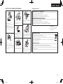
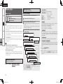
MULTI CHANNEL POWER AMPLIFIER
POA-3012CI
Owner’s Manual
Bedienungsanleitung
1.POA-3012CI_ENG.indd
1
2008/04/08
11:49:58
ENGLISH
DEUTSCH
nSAFETY PRECAUTIONS
CAUTION
RISK OF ELECTRIC SHOCK
DO NOT OPEN
CAUTION:
TO REDUCE THE RISK OF ELECTRIC SHOCK, DO NOT REMOVE
COVER (OR BACK). NO USER-SERVICEABLE PARTS INSIDE.
REFER SERVICING TO QUALIFIED SERVICE PERSONNEL.
The lightning flash with arrowhead symbol, within an equilateral
triangle, is intended to alert the user to the presence of
uninsulated “dangerous voltage” within the product’s enclosure
that may be of sufficient magnitude to constitute a risk of electric
shock to persons.
The exclamation point within an equilateral triangle is intended
to alert the user to the presence of important operating
and maintenance (servicing) instructions in the literature
accompanying the appliance.
WARNING:
TO REDUCE THE RISK OF FIRE OR ELECTRIC SHOCK, DO NOT
EXPOSE THIS APPLIANCE TO RAIN OR MOISTURE.
CAUTION:
•The ventilation should not be impeded by covering the ventilation
openings with items, such as newspapers, tablecloths, curtains,
etc.
•No naked flame sources, such as lighted candles, should be
placed on the unit.
•Observe and follow local regulations regarding battery disposal.
•Do not expose the unit to dripping or splashing fluids.
•Do not place objects filled with liquids, such as vases, on the
unit.
ACHTUNG:
•Die Belüftung sollte auf keinen Fall durch das Abdecken der
Belüftungsöffnungen durch Gegenstände wie beispielsweise
Zeitungen, Tischtücher, Vorhänge o. Ä. behindert werden.
•Auf dem Gerät sollten keinerlei direkte Feuerquellen wie
beispielsweise angezündete Kerzen aufgestellt werden.
•Bitte beachten Sie bei der Entsorgung der Batterien die örtlich
geltenden Umweltbestimmungen.
•Das Gerät sollte keiner tropfenden oder spritzenden Flüssigkeit
ausgesetzt werden.
•Auf dem Gerät sollten keine mit Flüssigkeit gefüllten Behälter
wie beispielsweise Vasen aufgestellt werden.
1.
2.
3.
4.
5.
6.
7.
8.
9.
10.
11.
12.
13.
IMPOTANT SAFETY
INSTRUCTIONS
Read these instructions.
Keep these instructions.
Heed all warnings.
Follow all instructions.
Do not use this apparatus near water.
Clean only with dry cloth.
Do not block any ventilation openings.
Install in accordance with the manufacturer's instructions.
Do not install near any heat sources such as radiators, heat registers,
stoves, or other apparatus (including amplifiers) that produce heat.
Do not defeat the safety purpose of the polarized or grounding-type plug. A
polarized plug has two blades with one wider than the other. A grounding
type plug has two blades and a third grounding prong. The wide blade or the
third prong are provided for your safety. If the provided plug does not fit into
your outlet, consult an electrician for replacement of the obsolete outlet.
Protect the power cord from being walked on or pinched particularly at
plugs, convenience receptacles, and the point where they exit from the
apparatus.
Only use attachments/accessories specified by the manufacturer.
Use only with the cart, stand, tripod, bracket, or table
specified by the manufacturer, or sold with the apparatus.
When a cart is used, use caution when moving the cart/
apparatus combination to avoid injury from tip-over.
Unplug this apparatus during lightning storms or when
unused for long periods of time.
14. Refer all servicing to qualified service personnel.
Servicing is required when the apparatus has been damaged in any way,
such as power-supply cord or plug is damaged, liquid has been spilled or
objects have fallen into the apparatus, the apparatus has been exposed to
rain or moisture, does not operate normally, or has been dropped.
CAUTION:
To completely disconnect this product from the mains, disconnect
the plug from the wall socket outlet.
The mains plug is used to completely interrupt the power supply to
the unit and must be within easy access by the user.
FCC INFORMATION (For US customers)
1. COMPLIANCE INFORMATION
Product Name: Multi Channel Power Amplifier
Model Number: POA-3012CI
This product complies with Part 15 of the FCC Rules. Operation is subject
to the following two conditions: (1) this product may not cause harmful
interference, and (2) this product must accept any interference received,
including interference that may cause undesired operation.
Denon Electronics (USA), LLC
(a D & M Holdings Company)
100 Corporate Drive
Mahwah, NJ 07430-2041
Tel. (800) 497-8921
2. IMPORTANT NOTICE: DO NOT MODIFY THIS PRODUCT
This product, when installed as indicated in the instructions contained
in this manual, meets FCC requirements. Modification not expressly
approved by DENON may void your authority, granted by the FCC, to use
the product.
3. NOTE
This product has been tested and found to comply with the limits for
a Class B digital device, pursuant to Part 15 of the FCC Rules. These
limits are designed to provide reasonable protection against harmful
interference in a residential installation.
This product generates, uses and can radiate radio frequency energy and,
if not installed and used in accordance with the instructions, may cause
harmful interference to radio communications. However, there is no
guarantee that interference will not occur in a particular installation. If this
product does cause harmful interference to radio or television reception,
which can be determined by turning the product OFF and ON, the user
is encouraged to try to correct the interference by one or more of the
following measures:
•Reorient or relocate the receiving antenna.
•Increase the separation between the equipment and receiver.
•Connect the product into an outlet on a circuit different from that to
which the receiver is connected.
•Consult the local retailer authorized to distribute this type of product or
an experienced radio/TV technician for help.
This Class B digital apparatus complies with Canadian ICES-003.
Cet appareil numérique de la classe B est conforme à la norme NMB-003 du
Canada.
VORSICHT:
Um dieses Gerät vollständig von der Stromversorgung abzutrennen,
ziehen Sie bitte den Stecker aus der Wandsteckdose.
Der Netzstecker wird verwendet, um die Stromversorgung zum
Gerät völlig zu unterbrechen; er muss für den Benutzer gut und
einfach zu erreichen sein.
I
1.POA-3012CI_ENG.indd
2
2008/04/08
9:25:33
DEUTSCH
nNOTE ON USE / HINWEISE ZUM GEBRAUCH
ENGLISH
nFor Europe model
DECLARATION OF CONFORMITY
We declare under our sole responsibility that this product, to which this declaration relates, is in
conformity with the following standards:
EN60065, EN55013, EN55020, EN61000-3-2 and EN61000-3-3.
Following the provisions of 2006/95/EC and 2004/108/EC Directive.
ÜBEREINSTIMMUNGSERKLÄRUNG
• Avoid high temperatures.
Allow for sufficient heat dispersion when
installed in a rack.
• Vermeiden Sie hohe Temperaturen.
Beachten Sie, dass eine ausreichende
Belüftung gewährleistet wird, wenn das
Gerät auf ein Regal gestellt wird.
• Do not let foreign objects into the unit.
• Keep the unit free from moisture, water, • Lassen Sie keine fremden Gegenstände in
and dust.
das Gerät kommen.
• Halten Sie das Gerät von Feuchtigkeit,
Wasser und Staub fern.
Wir erklären unter unserer Verantwortung, daß dieses Produkt, auf das sich diese Erklärung bezieht,
den folgenden Standards entspricht:
EN60065, EN55013, EN55020, EN61000-3-2 und EN61000-3-3.
Entspricht den Verordnungen der Direktive 2006/95/EC und 2004/108/EC.
DENON Europe
Division of D&M Germany GmbH
An der Landwehr 19, Nettetal,
D-41334 Germany
• Unplug the power cord when not using the • Do not let insecticides, benzene, and
thinner come in contact with the unit.
unit for long periods of time.
• Wenn das Gerät längere Zeit nicht • Lassen Sie das Gerät nicht mit Insektiziden,
Benzin oder Verdünnungsmitteln in
verwendet werden soll, trennen Sie das
Berührung kommen.
Netzkabel vom Netzstecker.
A NOTE ABOUT RECYCLING:
This product’s packaging materials are recyclable and can be reused. Please dispose of any materials
in accordance with the local recycling regulations.
When discarding the unit, comply with local rules or regulations.
Batteries should never be thrown away or incinerated but disposed of in accordance with the local
regulations concerning battery disposal.
This product and the supplied accessories, excluding the batteries, constitute the applicable product
according to the WEEE directive.
HINWEIS ZUM RECYCLING:
• Handle the power cord carefully.
Hold the plug when unplugging the cord.
• Gehen Sie vorsichtig mit dem Netzkabel
* (For apparatuses with ventilation holes)
um.
Halten Sie das Kabel am Stecker, wenn Sie
• Do not obstruct the ventilation holes.
den Stecker herausziehen.
• Decken Sie den Lüftungsbereich nicht ab.
• Never disassemble or modify the unit in
any way.
• Ne jamais démonter ou modifier l’appareil
d’une manière ou d’une autre.
Das Verpackungsmaterial dieses Produktes ist zum Recyceln geeignet und kann wieder verwendet werden. Bitte
entsorgen Sie alle Materialien entsprechend der örtlichen Recycling-Vorschriften.
Beachten Sie bei der Entsorgung des Gerätes die örtlichen Vorschriften und Bestimmungen.
Die Batterien dürfen nicht in den Hausmüll geworfen oder verbrannt werden; bitte entsorgen Sie die Batterien gemäß
der örtlichen Vorschriften.
Dieses Produkt und das im Lieferumfang enthaltene Zubehör (mit Ausnahme der Batterien!) entsprechen der WEEEDirektive.
II
1.POA-3012CI_ENG.indd
3
2008/04/08
9:25:34
ENGLISH
Getting Started
Contents
Connections
Getting Started
Accessories·······················································································1
Cautions on Handling······································································1
Cautions on Installation··································································1
Part Names and Functions······························································2
Front Panel······················································································2
Rear Panel·······················································································3
Setup
Operation
Troubleshooting
Specifications
Connections
Preparations·····················································································4
Before Connecting··········································································4
Cables Used for Connections·························································4
Speaker Connections······································································5
Connection Method When Outputting
2 Channels From One ZONE···························································5
Connection Method for BRIDGED Output··································5, 6
Input Connections···········································································7
BUS INPUT Connections·································································7
AUDIO INPUT Connections····························································7
Connections to Other Devices························································8
ETHERNET Connections·································································8
External controller···········································································9
• RS-232C Connector······································································9
• Trigger output jack········································································9
• Master trigger input jack·······························································9
• ZONE trigger input jacks·······························································9
Connecting the Power Cord························································· 10
Once Connections are Completed··············································· 10
Setup
Example of Display of Default Values·········································· 10
Operations······················································································ 10
Menu Map················································································ 11, 12
Main Setup····················································································· 13
a VOLUME CONTROL································································· 13
s INPUT SELECT········································································· 13
d LOW CUT FILTER····································································· 13
f OPERATION MODE································································· 13
g ZONE TRIGGER ON MODE······················································ 14
h DIMMER MODE······································································ 14
j POWER CONFIGURATION······················································ 14
Network Setup·············································································· 15
a Network Information································································ 15
s Network Setup··································································· 15, 16
Option Setup·················································································· 16
a Maintenance············································································· 16
s Firmware Update······································································ 16
Operation
Turning the Power On··································································· 17
Check the Status of Each Channel··············································· 17
Other Operations··········································································· 17
Other Operations During Playback················································ 17
Operating the POA-3012CI Using a Browser (Web control)····· 17, 18
Resetting the Microprocessor······················································· 18
Troubleshooting············································································ 19
Specifications················································································ 19
Getting Started
Thank you for purchasing this DENON product. To ensure proper
operation, please read this owner’s manual carefully before using the
product.
After reading them, be sure to keep them for future reference.
Accessories
Check that the following parts are supplied with the product.
qOwner’s manual....................................................................... 1
wWarranty (for North America model only)................................. 1
eService station list.................................................................... 1
rPower cord............................................................................... 1
Cord length:qNorth America model:6.6 ft /2.0 m
wEurope model:
5.2 ft /1.6 m
q
r
Cautions on Handling
•Before turning the ON/STANDBY switch on
Check once again that all connections are correct and that there are
no problems with the connection cables.
•Power is supplied to some of the circuitry even when the unit is
set to the standby mode. When traveling or leaving home for long
periods of time, be sure to unplug the power cord from the power
outlet.
•About condensation
If there is a major difference in temperature between the inside of
the unit and the surroundings, condensation (dew) may form on
the operating parts inside the unit, causing the unit not to operate
properly.
If this happens, let the unit sit for an hour or two with the power
turned off and wait until there is little difference in temperature
before using the unit.
•Cautions on using mobile phones
Using a mobile phone near this unit may result in noise. If so, move
the mobile phone away from this unit when it is in use.
•Moving the unit
Turn off the power and unplug the power cord from the power
outlet.
Next, disconnect the connection cables to other system units before
moving the unit.
•Note that the illustrations in these instructions may differ from the
actual unit for explanation purposes.
Cautions on Installation
Note:
For proper heat dispersal, do not install this unit in a confined
space, such as a bookcase or similar enclosure.
bNote
w
b
b
b
Wall
1.POA-3012CI_ENG.indd
4
2008/04/08
9:25:35
ENGLISH
Getting Started
Part Names and Functions
For buttons not explained here, see the page indicated in parentheses ( ).
Front Panel
Connections
e-q
Setup
Operation
Troubleshooting
Specifications
q
w
qPower operation button
(ON / STANDBY)·········································· (17)
wPower indicator············································ (17)
eDisplay·························································· (17)
e
r
rZONE select buttons··································· (10)
tZONE operation mode indicators·········· (6, 13)
ySETUP button·············································· (10)
uDISPLAY button··········································· (17)
t
y u
i
o Q0
iSELECT / ENTER knob································ (10)
oi (Down) button········································· (10)
Q0u (Up) / RETURN button···························· (10)
q Information display
Displays present status information and Setup
menu etc.,
1.POA-3012CI_ENG.indd
5
2008/04/08
9:25:35
ENGLISH
Getting Started
Rear Panel
Q0 o
i u
y
t
Connections
Setup
Operation
Troubleshooting
Specifications
q
w
qETHERNET connector···································· (8)
wRS-232C connector········································ (9)
eSpeaker terminals
(SPEAKER SYSTEMS)···································· (5)
rAC inlet (AC IN)············································ (10)
tAUDIO INPUT connectors····························· (7)
e
r
yTRIGGER IN jacks·········································· (9)
uMASTER TRIGGER OUT jack························· (9)
iBUS INPUT connectors································· (7)
oBUS OUTPUT connectors····························· (7)
Q0MASTER TRIGGER IN jack····························· (9)
1.POA-3012CI_ENG.indd
6
2008/04/08
9:25:36
ENGLISH
Preparations
Audio cables
Audio input connections
(Black)
Pin-plug cable
Businput/output connections (stereo)
nInput Setting
(Black)
L
L
(Black)
R
R
Stereo pin-plug cable
Select the input terminal to use.
Network connections
Troubleshooting
Each Zone input connectors or
BUS input connectors.
Operation
•Do not plug in the power cord until all connections have been
completed.
•When making connections, also refer to the operating instructions of
the other components.
•In the case of Bus input/output connections, be sure to connect the
left and right channels properly (left with left, right with right).
•Do not bundle power cords together with connection cables. Doing
so can result in humming or noise.
The POA-3012CI incorporates six sets of 2-channel amplifier from
ZONE1 to ZONE6.
The same audio signal can be output from all ZONE or separate
signals can be output from each ZONE. The POA-3012CI also supports
BRIDGED output.
Before making the connections, determine the input signals and
output signals for each ZONE and then set up the POA-3012CI in
accordance with the following procedure.
Setup
NOTE
Select the cables according to the equipment being connected.
Before Connecting
Connections
Connections for all compatible audio signal formats are described
in this owner’s manual. Please select the types of connections
suited for the equipment you are connecting.
With some types of connections, certain settings must be made
on the POA-3012CI. For details, refer to the instructions for the
respective connection items below.
Getting Started
Connections
Cables Used for Connections
Ethernet cable
Connect the external device to the input
terminal.
Speaker connections
Specifications
“INPUT SELECT” (vpage 13)
Speaker cables
Set the input source.
Signal direction
“Input Connection” (vpage 7)
Audio signal:
Output
Input
nOutput Setting
Select the speaker output method.
NORMAL output or BRIDGED
output
Input
Output
Connect the speaker cable.
“Speaker Connections”
(vpage 5)
Set the output channel.
“OPERATION MODE”
(vpage 13)
1.POA-3012CI_ENG.indd
7
2008/04/08
9:25:37
ENGLISH
Getting Started
Speaker Connections
Connection Method for BRIDGED Output
Connection Method When Outputting 2 Channels From One
ZONE
Connections
CH 1
CH 2
CH 3
CH 4
CH 9
CH 10
CH 11
CH 12
•In BRIDGED mode, one channel is output from one ZONE.
•To set BRIDGED mode, select “BRIDGED” as the “OPERATION MODE” on the “Main Setup” menu.
•When BRIDGED out putting a signal input to the AUDIO INPUT terminal, input to an even-numbered input
terminal.
•To select a signal for BRIDGED output from among the signals (“L”, “R”, “L+R”) input to the BUS INPUT
terminal, use “INPUT SELECT” on the “Main Setup” menu.
CH 1 & 2
CH 3 & 4
CH 5 & 6
CH 7 & 8
CH 9 & 10 CH 11 & 12
Setup
Operation
w
qw
w
q
qw
q
w
qw
w
q
qw
q
w
q
w
q
w
q
w
q
w
q
w
q
Troubleshooting
Specifications
CH 6
w
CH 5
qw
q
CH 8
w
CH 7
qw
q
1.POA-3012CI_ENG.indd
8
2008/04/08
9:25:38
ENGLISH
Carefully check the channel numbers and + (red) and – (black) polarities
on the speakers being connected to the POA-3012CI, and be sure to
interconnect the channels and polarities correctly.
Peel off about 0.03 ft/10 mm of sheathing
Turn the speaker terminal
counterclockwise to loosen it.
the hilt into the speaker terminal.
tighten it.
When using a banana plug (for North America model)
Specifications
Tighten the speaker terminal firmly before
inserting the banana plug.
Troubleshooting
Turn the speaker terminal clockwise to
Operation
Insert the speaker cable’s core wire to
Setup
2
3
4
from the tip of the speaker cable, then
either twist the core wire tightly or
terminate it.
If speakers with an impedance lower than specified (for example 4
Ω/ohms speakers/NORMAL MODE) are used for an extended period
of time with the volume turned up high, the temperature may rise,
activating the protection circuit.
There are 2 kind of protection circuits in POA-3012CI.
1.Protection circuit for individual Ampilfier (Zone1 ~ 6)
This protection circuit detects over load condition of the amplifier
circuit.
When the protection circuit is activiated, the speaker output of
individual Amplifier (Zone1 ~ 6) is shut off, and the Zone operation
mode indicator for protected Zone No. flashes red.
If this happen, unplug the power cord, then check the speaker
cable and input cable connections.
2.Temperature rise protection circuit in the chassis
This protection circuit detects temperature rising in the chassis.
When the protection circuit is activiated, the power source for all
Amplifier circuits is shut off, and the power indicator flashes red.
If this happen, it may be extremely hot in the chassis, unplug the
power cord.
Wait for it too cool off and improve ventilation around it.
Once this is done, plug the power cord back in and turn the set's
power back on.
If the protection circuit is activated again even though there are no
problems in the ventilation around the set nor in the connections,
the set may be damaged. Turn the power off, then contact a DENON
service center.
Connections
1
Protection circuit
Getting Started
Connecting the Speaker Cables
NOTE
•Use speakers with an impedance of 4 to 16 Ω/ohms. Use a 8 to 16
Ω/ohms speaker for BRIDGED output.
•Connect the speaker cables in such a way that they do not stick out
of the speaker terminals. The protection circuit may be activated if
the core wires touch the rear panel or if the + and – sides touch each
other (v “Protection circuit”).
•Never touch the speaker terminals while the power supply is
connected. Doing so could result in electric shock.
1.POA-3012CI_ENG.indd
9
2008/04/08
9:25:39
ENGLISH
Getting Started
Input Connections
BUS INPUT Connections
Connections
•To play signals input to the BUS INPUT terminal, select the channel
using “INPUT SELECT” on the “Main Setup” menu.
•When “BUS L+R” is used, signals input to BUS INPUT L and R are
mixed and output as monaural.
Audio Source
Setup
"6%*0
065
3
-
Operation
Troubleshooting
L
R
L
R
AUDIO INPUT Connections
nWhen Using in NORMAL MODE
To play signals input to the AUDIO INPUT terminal, use “INPUT
SELECT” on the “Main Setup” menu to set each channel to AUX.
GExampleH
Connect the left and right channels from audio source to audio
inputs of arbitrary numbers.
nWhen Using in BRIDGED MODE
Input BRIDGED output signals to an even-numbered input
terminal.
GExampleH
Connect the left and right channels from audio source to audio
inputs of arbitrary numbers.
Audio Source
Audio Source
"6%*0
065
3
"6%*0
065
3
-
Specifications
Signals input from the BUS INPUT are output from the BUS OUTPUT
terminal. These signals can be output to the BUS INPUT terminal of
another POA-3012CI unit.
1.POA-3012CI_ENG.indd
10
2008/04/08
9:25:41
ENGLISH
nBroadband Internet Connection
A broadband line connection to the Internet is required in order to
use the POA-3012CI’s firmware update.
ETHERNET Connections
nModem
Computer
Internet
nRouter
LAN port/
Ethernet
connector
nEthernet Cable (CAT-5 or greater recommended)
Specifications
•The POA-3012CI does not come with an Ethernet cable.
•Some flat type Ethernet cables are easily affected by noise.
We recommend using a normal type cable.
•If the sound is broken in an environment in which there is much
power supply noise from electric products or in a noisy network
environment, use a shielded type Ethernet cable (For North
America model).
•For the Ethernet cable, used a shielded twisted pair (STP) cable.
Do not use an unshielded twisted pair (UTP) cable, as it may exceed
noise standard limits (For Europe model).
•If you have an Internet provider contract for a line on which network
settings are made manually, make the settings at “Network Setup”
(vpage 15).
•With the POA-3012CI, it is possible to use the DHCP and Auto IP
functions to make the network settings automatically.
•When using a broadband router (DHCP function), the POA-3012CI
sets the IP address, etc., automatically.
When using the POA-3012CI connected to a network with no DHCP
function, make the settings for the IP address, etc., at “Network
Setup” (vpage 15).
•The POA-3012CI is not compatible with PPPoE. A PPPoE-compatible
router is required if you have a contract for a line of the type with
which the PPPoE is set.
Troubleshooting
To LAN port
nOthers
Operation
To LAN port
•When using the POA-3012CI, we recommend you use a router
equipped with the following functions:
· Built-in DHCP (Dynamic Host Configuration Protocol) server
This function automatically assigns IP addresses on the LAN.
· Built-in 100 BASE-TX switch
When connecting multiple devices, we recommend a switching
hub with a speed of 100 Mbps or greater.
Setup
To WAN side
Router
This is a device that is connected to the broadband line to
communicate with the Internet. Some are integrated with the
router.
NOTE
•A contract with an ISP is required to connect to the Internet.
No additional contract is needed if you already have a broadband
connection to the Internet.
•The types of routers that can be used depend on the ISP. Contact an
ISP or a computer shop for details.
Connections
Modem
For connections to the Internet, contact an ISP (Internet Service
Provider) or a computer shop.
Getting Started
Required System
Connections to Other Devices
nComputer
A computer with the following specifications is required to use a
server:
•OS
Windows® XP Service Pack2, Windows Vista
•Internet browser
Microsoft Internet Explorer 5.01 or later
•LAN port
1.POA-3012CI_ENG.indd
11
2008/04/08
9:25:42
ENGLISH
Getting Started
External Controller
RS-232C connector
Connections
This connector is used for an external controller.
Setup
Operation
b If you wish to control the POA-3012CI from
an external controller using the RS-232C
connector, perform the operation below
beforehand.
q Turn the POA-3012CI’s power.
w Turn off the POA-3012CI’s power from the
external controller.
e Check that the POA-3012CI is in the standby
mode.
Troubleshooting
Trigger output jack
Specifications
The power of an external device equipped with
a trigger input jack can be turned on and off in
association with operations on the POA-3012CI.
•Output level: 250 mA/12 V
Check the trigger input conditions of the
connected device.
•If the trigger input level of the connected device
is higher than 250 mA/12 V and depending on
the short-circuiting conditions, the POA-3012CI’s
protection circuit may be activated, in which
case “TRIGGER OUT OVER LOAD” appears on
the display. If this happens, turn off the POA3012CI’s power and disconnect the connected
device.
Master trigger input jack
he “POWER CONFIGURATION” setting is valid
T
at the time of a “MASTER TRIGGER”.
Voltage input to the MASTER TRIGGER input
terminal and operating status of the POA-3012CI:
At DC 3 ~ 30 V····················· ON
At DC 0 V····························· STANDBY
ZONE trigger input jack
The ZONE TRIGGER ON MODE setting is valid at
the time of a “TRIGGER IN”.
Voltage input to the TRIGGER IN input terminal
and operating status of the power amplifier of
each ZONE:
At DC 3 ~ 30 V····················· ON
At DC 0 V····························· STANDBY
1.POA-3012CI_ENG.indd
12
2008/04/08
9:25:43
ENGLISH
Wait until all connections have been completed before connecting the
power cord.
n To select the item to be set
Setup
Turn the SELECT/ENTER knob until the item you want to set
appears.
n To enable lower level menu items to be displayed
u/RETURN
SETUP
i
Press the SELECT/ENTER knob or the i button.
n To return to higher level menu items
Press the u/RETURN button.
Setup
n To confirm selected item
Press the SELECT/ENTER knob.
n To exit SETUP mode
Press the SETUP button until the display returns to normal.
ZONE1~6
NOTE
SELECT/ENTER
Insert the AC plugs securely. Incomplete connections could cause
noise.
Turning the Power On (vpage 17)
In lists of selectable items or adjustable ranges, the item
surrounded by a border is the default value.
[Selectable items]
Bright
Dim
Dark
Specifications
Once Connections are Completed
Example of Display of Default
Values
If you want to configure the settings for a specific ZONE, press
the ZONE 1 ~ 6 button for the ZONE concerned and configure the
settings.
• In this case, the setting item of another ZONE is not displayed.
• To configure the settings for “DIMMER MODE” and “POWER
CONFIGURATION”, use the SETUP button to select “Main Setup”
mode.
Troubleshooting
Europe model:
To household power
outlet
(AC 230 V, 50 Hz)
Operation
Power cord
(included)
Connections
North America model:
To household power
outlet
(AC 120 V, 60 Hz)
Getting Started
Using the menu
Connecting the Power Cord
OFF
Operations
For all settings, refer to “Menu map” (vpage 11, 12).
For details of individual settings refer to the explanations of settings
(vpage 13 ~ 16).
1
Press the SETUP button.
The POA-3012CI enters the “SETUP” mode and the first level
menu is displayed.
The selected item blinks.
2
Select the required item on the menu and set it.
0
1.POA-3012CI_ENG.indd
13
2008/04/08
9:25:45
ENGLISH
Getting Started
Menu Map
NORMAL MODE
Connections
Main Setup
(vpage 13)
CH 1
CH 2
CH 3
aVOLUME CONTROL
(vpage 13)
0.0dB
–90.0dB
– – –.–dB
CH 12
BRIDGED MODE
CH 2 BTL
CH 4 BTL
CH 6 BTL
BTL 0.0dB
BTL –90.0dB
BTL – – –.–dB
CH 12 BTL
Setup
CH 1
CH 2
CH 3
Operation
sINPUT SELECT
(vpage 13)
AUX.1
BUS L
BUS R
BUS L+R
Troubleshooting
CH 12
CH 1
CH 2
CH 3
dLOW CUT FILTER
(vpage 13)
Specifications
fOPERATION MODE
gZ
ONE TRIGGER ON
MODE
(vpage 14)
hDIMMER MODE
(vpage 14)
Network Setup
Option Setup
jP
OWER
CONFIGURATION
BTL AUX.2
BTL BUS L
BTL BUS R
BTL BUS L+R
CH 12 BTL
LCF OFF
LCF ON
CH 12
(vpage 13)
CH 2 BTL
CH 4 BTL
CH 6 BTL
CH 2 BTL
CH 4 BTL
CH 6 BTL
BTL LCF OFF
BTL LCF ON
CH 12 BTL
CH 1 & 2
CH 3 & 4
CH 5 & 6
CH 7 & 8
CH 9 & 10
CH 11 & 12
NORMAL
BRIDGED
CH 1 & 2
CH 3 & 4
CH 5 & 6
CH 7 & 8
CH 9 & 10
CH 11 & 12
CONSTANT
TRIG. IN
A.SIGNAL
OFF
CH 1 & 2
CH 3 & 4
CH 5 & 6
CH 7 & 8
CH 9 & 10
CH 11 & 12
BRIDGED
NORMAL
Bright
Dim
Dark
OFF
POWER BUTTON
ON LINE
MASTER TRIGGER
11
1.POA-3012CI_ENG.indd
14
2008/04/08
9:25:46
ENGLISH
Getting Started
Main Setup
Network Setup
aN
etwork
Information
(vpage 15)
DHCP
Connections
(vpage 15)
IP Address
Mac Address
Setup
Operation
DHCP
OFF
ON
IP Address
Subnet Mask
Default Gateway
Primary DNS
Secondary DNS
Address
Name
Option Setup
(vpage 16)
Specifications
Proxy
ON
OFF
Troubleshooting
sNetwork Setup
(vpage 15)
Proxy Address
Port
Proxy Name
Port
aMaintenance
(vpage 16)
sFirmware Update
(vpage 16)
12
1.POA-3012CI_ENG.indd
15
2008/04/08
9:25:47
ENGLISH
Getting Started
Main Setup
F Menu tree F
Main Setup
a VOLUME CONTROL
Connections
s INPUT SELECT
d LOW CUT FILTER
sINPUT SELECT
fOPERATION MODE
Sets the input terminal for each channel.
Sets the output method for channels in each ZONE.
[Selectable Channels]
[Selectable Channels]
For details of the channels which can be set in each mode, see
GSelectable ChannelsH in “ a VOLUME CONTROL”.
Sets each of the following channel pairs.
[Selectable items]
f OPERATION MODE
AUX
Setup
g ZONE TRIGGER ON MODE
:AUDIO INPUT terminal of each ZONE.
Operation
h DIMMER MODE
BUS L
:L terminal of BUS INPUT
j POWER CONFIGURATION
BUS R
:R terminal of BUS INPUT
BUS L+R :L and R terminals of BUS INPUT .
Inputs a L and R mixed mono signal.
Troubleshooting
aVOLUME CONTROL
dLOW CUT FILTER
[Selectable Channels]
Channels which can be set in each mode.
Specifications
NORMAL MODE
S
S
S
S
S
S
S
S
S
S
S
S
S: Setting possible
A: Setting not possible
[Variable range] – – –.–dB (– ∞)
NORMAL MODE
S
S
S
S
S
S
[Selectable items]
BRIDGED MODE
S
S
S
S
S
S
Default: NORMAL MODE
NORMAL :2-channel output
Sets the volume level for each channel.
CH 1
CH 2
CH 3
CH 4
CH 5
CH 6
CH 7
CH 8
CH 9
CH 10
CH 11
CH 12
CH 1 & 2
CH 3 & 4
CH 5 & 6
CH 7 & 8
CH 9 & 10
CH 11 & 12
BRIDGED MODE
A
S
A
S
A
S
A
S
A
S
A
S
Default: NORMAL MODE
–90.0dB
~
Cuts the low frequency component of each channel.
Turn this “ON” when there is a high volume of low
frequency sound.
[Selectable Channels]
For details of the channels which can be set in each mode, see
GSelectable ChannelsH in “ a VOLUME CONTROL”.
[Selectable items]
ON
:Low frequency component is cut.
OFF
:Low frequency component is not cut.
BRIDGED :BRIDGED-channel output (1-channel output)
•During NORMAL MODE, ZONE operations mode indicators are lit
green.
•During BRIDGED MODE, ZONE operations mode indicators are lit
orange.
NOTE
The method of connecting speakers differs for each mode. Connect
the speakers in accordance with the mode setting. For details, refer to
“Speaker Connection” (vpage 5).
0.0dB
13
1.POA-3012CI_ENG.indd
16
2008/04/08
9:25:47
ENGLISH
hDIMMER MODE
Sets the operating specifications for the power amplifiers
of each ZONE.
Adjust display brightness of the POA-3012CI.
Getting Started
gZONE TRIGGER ON MODE
[Selectable items]
Bright
For details of the channels which can be set in each mode, see
GSelectable ChannelsH in “ f OPERATION MODE” (vpage 13).
[Selectable items]
Dim
:Reduced display brightness.
Dark
:Very low display brightness.
OFF
:Display is off unless controls are operated.
Setup
CONSTANT :The power amplifier operates constantly.
:Normal display brightness.
Connections
[Selectable Channels]
TRIG. IN
Operation
:The power amplifier operates when trigger input is
detected.
When trigger input is not detected, it remains in
standby mode.
When setting to “Dim”, “Dark” and “OFF”, the display brightness
changes to “Bright” for about 3 seconds during the operation before
reverting to the set brightness.
Troubleshooting
A.SIGNAL :The power amplifier operates when an audio signal is
input.
If no input is received for a period of 10 minutes, it
jPOWER CONFIGURATION
switches to standby mode.
OFF
Select the method for turning on the POA-3012CI.
:Turns the power amplifier off.
POWER BUTTON
The POA-3012CI accepts +3 ~ 30V trigger input.
ON LINE
Specifications
[Selectable items]
:Operate with the ON/STANDBY button only.
:Operate from an external device via Ethernet
or RS-232C input.
MASTER TRIGGER :Operate by detection of a trigger signal input
to the MASTER TRIGGER input terminal.
•Turns on when a signal is detected.
•If no input is received for a period of 10
minutes, it switches to standby mode.
•The POA-3012CI accepts +3 ~ 30 V trigger input.
•Even when “ON LINE” or“MASTER TRIGGER” has been set, power
source operation is possible by means of ON/STANDBY button.
14
1.POA-3012CI_ENG.indd
17
2008/04/08
9:25:48
ENGLISH
Getting Started
Network Setup
sNetwork Setup
Make network settings.
Make settings for wired LAN.
Wired LAN settings
F Menu tree F
Connections
Main Setup
Use this procedure to configure the Wired LAN settings.
Network Setup
a Network Information
s Network Setup
1
2
Connect the LAN cable (vpage 8).
Setup
Turn on the POA-3012CI (vpage 17).
POA-3012CI performs automatic network setup due to the DHCP
Operation
Troubleshooting
Specifications
•If you are using a broadband router (DHCP function), there is no need
to make the settings at “Setting the IP Address” and “Setting the
Proxy”, since the DHCP function is set to “ON” in the POA-3012CI’s
default settings.
•If the POA-3012CI is being used connected to a network without the
DHCP function, the network settings must be made. In this case,
some knowledge of networks is required. For details, consult a
network administrator.
•If you cannot connect to the Internet, recheck the connections and
settings (vpage 8).
• If you do not understand about Internet connection, contact your ISP
(Internet Service Provider) or the store from which you purchased
your computer.
•DHCP (Dynamic Host Configuration Protocol) :
These are systems by which the IP address and other network
settings are automatically set for the POA-3012CI, computer,
broadband router and network devices.
•DNS (Domain Name System) :
This is a system for converting the domain names used when
browsing Internet sites (for example, “www.denon.jp”) into the
IP addresses actually used for communications (for example,
“202.221.192.106”).
aNetwork Information
Display network information.
3
function.
When connecting to a network that has no DHCP function,
perform the setting in step 3.
Set the IP address at the menu “Network Setup” –
“Network Setup”.
*Network Setup
DHCP
1
Subnet Mask
255.255.255.
Primary DNS Secondary DNS :
If there is only one DNS address indicated in the documentation
supplied by your provider, input it at “Primary DNS”. If there are
two or more DNS addresses, input the first one at “Secondary
DNS”.
rPress the SELECT/ENTER knob.
Setup is complete.
0
bWhen connecting to the network via a Proxy server, select
“Proxy” and press the SELECT/ENTER knob (vpage 16 “Proxy
Default Gateway
0. 0. 0. 1
Primary DNS
0. 0. 0.
Subnet Mask :
When connecting an xDSL modem or terminal adapter directly
to the POA-3012CI, input the subnet mask indicated in the
documentation supplied by your provider. Normally input
255.255.255.0.
Default Gateway :
When connected to a gateway (router), input its IP address.
w Set “OFF”.
IP Address
192.168. 0.
IP Address :
Set the IP address within the ranges shown below. The Network
function cannot be used if other IP addresses are set.
CLASS A: 10.0.0.0 ~ 10.255.255.255
CLASS B: 172.16.0.0 ~ 172.31.255.255
CLASS C: 192.168.0.0 ~ 192.168.255.255
*DHCP
OFF
qSelect “DHCP”.
eUse the following buttons to input the address and press the
SELECT/ENTER knob.
bButton functions when entering address
SELECT/ENTER knob :Turn·············Select
Press···········Confirm
u button : Cursor to right
i button : Cursor to left
ZONE 6 button : Setting during address entry
ZONE 5 button : Cancel entry
settings”).
0
Secondary DNS
0. 0. 0. 0
eInput the address.
[Items to be checked] DHCP= ON or OFF IP Address
MAC Address
qSelect “DHCP” and press the SELECT/ENTER knob.
wTurn the SELECT/ENTER knob to set “DHCP” to “OFF”, then
press the SELECT/ENTER knob.
The DHCP function is disabled.
15
1.POA-3012CI_ENG.indd
18
2008/04/08
9:25:49
ENGLISH
Make this setting when connecting to the Internet via a proxy server.
wSet “ON”.
*Proxy
ON
*Proxy
Proxy Address
tTurn the SELECT/ENTER knob to select the “Port” and press
SELECT/ENTER knob.
Execute the update process.
When updating starts, the power indicator lights red. “Updating
zzz” is shown on the display during updating. Once updating is
completed, “Updatingcomplete” is displayed.
“Latest firmware” is displayed when the firmware is the latest
version.
yUse the above buttons to input the proxy server port number and
press the SELECT/ENTER knob.
bIf the display reads as shown below, check the settings and network
environment, then update again.
uPress the SELECT/ENTER knob.
Setup is complete.
Updating failed
Updating failed.
Login failed
Failure to log into server.
Server is busy
Server is busy. Wait a while then try again.
Connection fail
Failure connecting to server.
Option Setup
Make various other settings.
yInput the port
number.
*Proxy Port
00000
qSelect menu “Network Setup” – “Network Setup” – “Proxy” and
press the SELECT/ENTER knob.
F Menu tree F
Main Setup
Option Setup
a Maintenance
wTurn the SELECT/ENTER knob to set “Proxy” to “ON” and press
the SELECT/ENTER knob.
The proxy server is enabled.
eTurn the SELECT/ENTER knob to select the proxy server input
method, and then press the i button.
[Selectable items]
Address :Select when inputting by address.
:Select when inputting by domain name.
Name
[Characters that can be input]
A ~ Z
a~z
0~9
! # % & ’ ( ) * + , - . / : ; = ˉ ? @ [ \ ] (space)
Update Start
s Firmware Update
aMaintenance
This sets the function for maintenance by a DENON
serviceperson or installer. (For professional use only.)
This function allows a DENON serviceperson or installer to check the
POA-3012CI’s status and make settings via the Internet.
NOTE
Only use this function if so instructed by a DENON serviceperson or
installer.
Display
Description
NOTE
•Connection to the network and specific settings are required to
update the firmware. For details, see page 8, 15.
•Do not turn off the power until updating is completed.
•Normally there is no need to use this function, aside from the cases
described below.
⋅ The Firmware Update function is only used for updating the
firmware (free or for a charge) via the Internet, for example for the
purpose of adding functions to the POA-3012CI in the future.
⋅ Information regarding the Firmware Update function will be
announced on the DENON web site each time related plans are
defined.
⋅ A broadband connection to the Internet is required to use this
function (v page 8).
⋅ Even with a broadband connection to the Internet, approximately
13 min is required for the updating procedure to be completed.
Once updating starts, normal operations on the POA-3012CI cannot
be performed until updating is completed.
Furthermore, updating the firmware may reset the backup data for
the parameters, etc., set for the POA-3012CI.
Specifications
*Proxy
Port
tSelect “Port”.
You can check for firmware updates. You can also check approximately
how long it will take to complete an update.
Troubleshooting
*Proxy Address
000.000.000.000
Update Check
Operation
rInput the
address
or domain
name.
*Proxy
Address
Update the firmware of the multi channel power amplifier.
Setup
eSelecting the
input method
Example) Address
sFirmware Update
Connections
qSelect “Proxy”.
*Network Setup
Proxy
rUse the following buttons to input the proxy server address or
domain name and press the SELECT/ENTER knob.
bButton functions when entering address
SELECT/ENTER knob :Turn·············Select
Press···········Confirm
u button : Cursor to right
i button : Cursor to left
ZONE 6 button : Setting during address entry
ZONE 5 button : Cancel entry
DISPLAY button : Character insert/delete/overwrite
Cursor 1 : Character insert
Cursor 0 : delete
Cursor 2 : overwrite
When “Address” is selected in step e :Input the address
When “Name” is selected in step e :Input the domain name
Getting Started
nProxy settings
16
1.POA-3012CI_ENG.indd
19
2008/04/08
9:25:50
ENGLISH
Getting Started
Check the Status of Each Channel
1
Press the DISPLAY button.
Operation
Connections
ZONE operation mode indicators
SELECT/ENTER
b Zone status is indicated on the bottom line of the display.
b Turn the SELECT/ENTER knob to change the display as follows.
Channel No. & INPUT Line
ZONE T.ON MODE
VOLUME CONTROL level
LOW CUT FILTER
Setup
2
Press the DISPLAY button again.
Operation
b System status is indicated on the bottom line of the display.
b Turn the SELECT/ENTER knob to change the display as follows.
Troubleshooting
ON/STANDBY
POWER CONFIG
ZONE 5
DISPLAY
u/RETURN
Turning the Power On
Specifications
Press the ON/STANDBY button.
The power indicator flashes green and the power turns on.
b The signal input to each channel is output from the speaker
terminal of each channel.
b The setting status of each channel is indicated on the display.
b Turn the SELECT/ENTER knob to change the channel displayed.
Output channel
Input terminal
CH 1&2
BTL
BUS L+R
0.0dB
OPERATION MODE
Volume level
(No display when in “NORMAL MODE”)
n To return to STANDBY
Press the ON/STANDBY button again.
The power indicator lights red.
DIMMER
n To Return to the Regular Display
Operating the POA-3012CI
Browser (Web control)
Using
a
This function lets you operate the POA-3012CI using Internet
Explorer.
1
Check the POA-3012CI’s IP Address.
“Network Setup” – “Network Information” (vpage 15)
2
Input the POA-3012CI’s IP Address in Internet
Explorer.
For example, if the IP address is “10.3.18.90”, enter
http://10.3.18.90.
3
If the top menu is displayed, click “Setup Menu”.
Press the u/RETURN button until the display returns to normal.
Other Operations
Click
Other Operations During Playback
n To Adjust the Volume
Refer to “VOLUME CONTROL” on the “Main Setup” menu
(vpage 13).
n To Switch Input Setting
Refer to “INPUT SELECT” on the “Main Setup” menu (vpage
13).
n To Reduce the Low Frequency Volume
Refer to “LOW CUT FILTER” on the “Main Setup” menu (vpage
13).
4
When the “Setup Menu” is displayed, click on the
menu you want to operate.
Click the menu
CHANNEL SETUP (vExample : 1)
SYSTEM SETUP (vExample : 2)
WARNING AND PROTECTION DATA
(vExample : 3)
AUDIO SIGNAL AND TRIGGER
INPUT (vExample : 4)
OPTION SETUP (vExample : 5)
NOTE
• When the “POWER CONFIGURATION” is set to “MASTER
TRIGGER”, the device will automatically enter the standby status
when no trigger input is detected for a period of 10 minutes.
• When the “POWER CONFIGURATION” is set to “ON LINE”, send
a standby command to the ETHERNET terminal or the RS-232C
terminal of the POA-3012CI.
• Power continues to be supplied to some of the circuitry even when
the power is in the standby mode. When leaving home for long
periods of time or when traveling, unplug the power cord from the
power outlet.
Click “SAVE” when you want to save settings,
and click “LOAD” when you want to call settings
Becomes each operation screen
1.POA-3012CI_ENG.indd
20
2008/04/08
9:25:51
ENGLISH
Operate.
GExample: 3H Warning and Protection Data Screen
To use the web control function, set the menu “Main Setup”– “POWER
CONFIGURATION” – “ON LINE” (vpage 14).
GExample: 1H Channel Setup Screen
Click when you update to
the latest information (z)
NOTE
GExample: 4H Audio Signal and Trigger Input Screen
Displays On/Off of
Audio signal and
Trigger In.
No setting item.
Enter figures or click “< ” or “>” to make
the setting, and then click “Set”.
GExample: 2H System Setup Screen
Click “v” and select
from the displayed
items.
Unplug the power cord from the power outlet.
Connect the power cord to the power outlet while
GExample: 5H Option Setup Screen
Click “S” for the item
you want to set.
simultaneously pressing the
buttons.
3
ZONE 5 and DISPLAY
When all Zone operation mode indicators are
Specifications
z:Normally, there is a change to the latest information each time
you operate. When operated from the main unit, click because the
screen is not updated.
1
2
Troubleshooting
Click on the tab you want to set, and
select from the displayed items.
Perform this procedure if the display is abnormal or if
operations cannot be performed.
When the microprocessor is reset, all the settings are
reset to their default values.
Operation
Resetting the Microprocessor
Setup
Displays Warning and
Protection Data.
Connections
•To perform web control, you must connect a web control device
such as a PC to the same network as the POA-3012CI.
•With web control, some network settings, etc., cannot be set.
•When updating firmware, settings made by the web controller may
be reset.
Getting Started
5
illuminated in red and “ zEEPROM INIT.z” is
displayed, release finger from two buttons.
If in step 3 the could not be start over from step 1.
Click when Firmware
Update starts.
18
1.POA-3012CI_ENG.indd
21
2008/04/08
9:25:52
ENGLISH
Getting Started
Troubleshooting
Specifications
Connections
Setup
Check the following before assuming there is a problem with the set:
1. Are all connections proper?
2. Is the set being operated as described in the owner’s manual?
3. Are the speakers and input components being operated properly?
If the set does not seem to be operating properly, check the points listed below. If these points do not
apply, the set may be damaged. Turn off the power immediately and contact your store of purchase.
Operation
Troubleshooting
Specifications
Symptom
Cause
When the power is •The power supply cord’s plug is
turned on, the power not fully plugged in.
indicator does not
light and no sound
is produced.
The power indicator •The speaker cables are not fully
lights but no sound connected.
is produced.
•The device you want to listen to
has not been selected.
•The volume control is set to
minimum.
•The input cable is not fully
connected.
•The speaker cable is not
connected properly for the
operation mode.
Countermeasure
•Make sure the unit is correctly
plugged in and switched on at
the mains socket.
Page
10
•Connect securely.
5
•Insure the correct input is
selected.
•Set to an appropriate level.
7
17
•Connect securely.
7
•Connect
the
speaker
as
required for the Operation Mode
(NORMAL MODE or BRIDGED
MODE).
•The input connector is not •Connect the input connector
connected properly.
correctly (in the case of BRIDGED
input for each ZONE, input to an
even-numbered channel.)
•The “Turn On” command is not •Send the “Turn On” command
input from the external terminal from the external device.
when the ZONE TRIGGER ON
MODE is set to ON LINE (the
ZONE operation mode indicator
is not lit).
•Trigger voltage is not input to •Input the trigger voltage from
the TRIGGER IN terminal from the external device.
the external device when the
ZONE TRIGGER ON MODE is
set to “TRIG. IN”.
5
Rated output:
12-channel driving, NORMAL operation:
30 W x 12 ch (8 Ω/ohms, DIN 1 kHz with 0.7 % T.H.D.)
50 W x 12 ch (4 Ω/ohms, DIN 1 kHz with 0.7 % T.H.D.)
6-channel driving, BRIDGED operation:
100 W x 6 ch (8 Ω/ohms, DIN 1 kHz with 0.7 % T.H.D.)
0.05% (Rated output: –3 dB, 8 Ω/ohms, 1 kHz)
Total harmonic distortion:
Speaker 4 ~ 16 Ω/ohms (NORMAL operation)
Output terminals:
Speaker 8 ~ 16 Ω/ohms (BRIDGED operation)
550 mV / 47 kΩ/kohms (NORMAL operation)
Input sensitivity / Input impedance:
275 mV / 47 kΩ/kohms (BRIDGED operation)
29 dB (NORMAL operation)
Gain:
35 dB (BRIDGED operation)
5 Hz ~ 40 kHz (Low cut filter: OFF)
Frequency response:
95 dB (input terminals short-circuited, with A-weightied network)
S/N raito:
Cut off freguency 80 Hz (–12 dB/oct. Low cut filter: ON)
Low cut filter:
3 ~ 30 V DC
Trigger in level:
12 V DC, 250 mA MAX
Trigger out level:
AC 120 V, 60 Hz (North America model) / AC 230 V, 50Hz (Europe model)
Power Supply:
Power Consumption:
2.5 A (North America model) / 230 W (Europe model)
Standby: 0.5 W or less
(When the “POWER CONFIGURATION” is set to “POWER BUTTON”)
Maximum external dimension:
434 (W) x 171 (H) x 410 (D) mm (17-3/32” x 6-47/64” x 16-9/64”)
19.0 kg (Approx 41 lbs 14.2 oz)
Weight:
bFor purposes of improvement, specifications and design are subject to change without notice.
7
9, 14
9, 14
19
1.POA-3012CI_ENG.indd
22
2008/04/08
9:25:52
20
1.POA-3012CI_ENG.indd
23
2008/04/08
9:25:52
www.denon.com
Denon Brand Company, D&M Holdings Inc.
Printed in Japan 00D 511 4719 004
3.POA-3012CI_Backpage.indd
1
2008/04/08
9:28:48