1
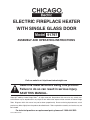
ELECTRIC FIREPLACE HEATER
WITH SINGLE GLASS DOOR
Model 91797
ASSEMBLY and Operating Instructions
Visit our website at: http://www.harborfreight.com
Read this material before using this product.
Failure to do so can result in serious injury.
Save this manual.
Copyright© 2004 by Harbor Freight Tools®. All rights reserved. No portion of this manual or any artwork contained herein may be reproduced in any shape or form without the express written consent of Harbor Freight
Tools. Diagrams within this manual may not be drawn proportionally. Due to continuing improvements, actual
product may differ slightly from the product described herein. Tools required for assembly and service may not
be included.
For technical questions or replacement parts, please call 1-800-444-3353.
Revised Manual 10d
SPECIFICATIONS
ITEM
DESCRIPTION
Power Requirements
120 VAC, 60 Hz, 15 Amps
Heater Settings
750 and 1500 Watts
Heater Controls
Fan On/Off switch; 2 -2750W On/Off switches;
Fire light On/Off switch; Temperature thermostate knob; Fire light brightness knob; Remote
Control Unit
Line Cord
Two-prong polarized plug; 16 AWG x 2C; UL
listed
Light Bulbs
2 - 60W candelabra bulbs
Overall Dimensions
20-3/8 (L) x 11-1/2 (W) x 22-3/4 (H) inches
Weight
39 Lbs.
The maximum room size of the heater is 400 square foot.
SAVE THIS MANUAL
You will need the manual for the safety warnings and precautions, assembly instructions,
operating and maintenance procedures, parts list and diagram. Keep your invoice with this
manual. Write the invoice number on the inside of the front cover. Keep the manual and
invoice in a safe and dry place for future reference.
GENERAL SAFETY RULES
WARNING!
READ AND UNDERSTAND ALL INSTRUCTIONS. Failure to follow all instructions
listed below may result in electric shock, fire, and/or serious injury.
SAVE THESE INSTRUCTIONS
WORK AREA
1.
Keep the area surrounding this appliance clean and orderly.
2.
Do not operate this heater in explosive atmospheres, such as in the presence of
flammable liquids, gases, or dust.
REV 07j; 08d
SKU 91797
For technical questions, please call 1-800-444-3353
Page 2
Electrical Safety
3.
Avoid body contact with grounded surfaces such as pipes, radiators, ranges,
and refrigerators. There is an increased risk of electric shock if your body is
grounded.
4.
Do not expose appliances to rain or wet conditions. Water entering a appliance
will increase the risk of electric shock.
5.
Grounded products must be plugged into an outlet properly installed and
grounded in accordance with all codes and ordinances. Never remove the
grounding prong or modify the plug in any way. Do not use any adapter plugs.
Check with a qualified electrician if you are in doubt as to whether the outlet
is properly grounded. If the product should electrically malfunction or break down,
grounding provides a low resistance path to carry electricity away from the user.
6.
Double insulated appliances are equipped with a polarized plug (one blade is
wider than the other). This plug will fit in a polarized outlet only one way. If
the plug does not fit fully in the outlet, reverse the plug. If it still does not fit,
contact a qualified electrician to install a polarized outlet. Do not change
the plug in any way. Double insulation
eliminates the need for the three wire
grounded power cord and grounded power supply system.
7.
Do not abuse the Power Cord. Never use the Power Cord to pull the Plug from
an outlet. Keep the Power Cord away from heat, oil, sharp edges, or moving
parts. Replace damaged Power Cords immediately. Damaged Power Cords
increase the risk of electric shock.
Personal Safety
8.
Stay alert. Watch what you are doing, and use common sense when operating
this product.
9.
Avoid accidental starting. Be sure the Fan Switch is off before plugging in.
Tool Use and Care
10. Do not use this appliance if any switch or thermostat does not work properly.
11. Disconnect the Power Cord Plug from the power source before making any
adjustments to the appliance. Such preventive safety measures reduce the risk of
starting the appliance accidentally.
Service
12. Appliance service must be performed only by qualified repair personnel.
Service or maintenance performed by unqualified personnel could result in a risk of
injury.
SKU 91797
For technical questions, please call 1-800-444-3353
Page 3
13. When servicing an appliance, use only identical replacement parts. Follow
instructions in the “Inspection, Maintenance, And Cleaning” section of this
manual. Use of unauthorized parts or failure to follow maintenance instructions may
create a risk of electric shock or injury.
SPECIFIC SAFETY RULES FOR THIS PRODUCT
1.
Maintain labels and nameplates on the Fireplace Heater. These carry important
information. If unreadable or missing, contact Harbor Freight Tools for a replacement.
2.
Avoid fires and explosions. Never place the Fireplace Heater near room curtains
or other flammable materials. The floor on which the Fireplace Heater sits must be
nonflammable and free of debris. Never use near flammable vapors or liquids.
3.
Maintain a safe working environment. Keep the work area well lit. Make sure there
is adequate surrounding space. Always keep the work area free of obstructions,
grease, oil, trash, and other debris. Do not use this product in areas near flammable
chemicals, dusts, and vapors. Do not use this product in a damp or wet location.
4.
Avoid unintentional starting. Make sure you are prepared to begin work before
turning on the Fireplace Heater.
5.
Do not force the Fireplace Heater. This product will do the work better and safer at
the capacity for which it was designed.
6.
Always unplug the Fireplace Heater from its electrical outlet before performing
and inspection, maintenance, or cleaning procedures.
7.
Never leave the Fireplace Heater unattended while running. Turn power off if you
have to leave the room.
8.
Use proper extension cord. If an extension cord is used, use the proper type as
listed in the table on page 7. Keep extension cord off the ground and away from water.
9.
Connect to a GFCI outlet. Always connect the Line Cord to a Ground Fault Circuit
Interrupter (GFCI) protected electrical outlet.
GROUNDING
Note: This product comes with a two-prong, polarized plug.
WARNING!
Improperly connecting the grounding wire can result in the risk of electric
shock. Check with a qualified electrician if you are in doubt as to whether
the outlet is properly grounded. Do not modify the power cord plug provided
with the tool or product. Never remove the grounding prong from the plug.
Do not use the tool if the power cord or plug is damaged. If damaged, have
it repaired by a service facility before use. If the plug will not fit the outlet,
have a proper outlet installed by a qualified electrician.
SKU 91797
For technical questions, please call 1-800-444-3353
Page 4
Grounded Tools: Appliances with Three Prong Plugs
1.
Appliances marked with “Grounding Required” have a three wire cord and three prong
grounding plug. The plug must be connected to a properly grounded outlet. If the
appliance should electrically malfunction or break down, grounding provides a low
resistance path to carry electricity away from the user, reducing the risk of electric
shock. (See Figure A.)
2.
The grounding prong in the plug is connected through the green wire inside the cord
to the grounding system in the appliance. The green wire in the cord must be the only
wire connected to the appliance’s grounding system and must never be attached to an
electrically “live” terminal. (See Figure A.)
3.
Your appliance must be plugged into an appropriate outlet, properly installed and
grounded in accordance with all codes and ordinances. The plug and outlet should
look like those in the following illustration. (See Figure A.)
Figure A
Figure B
Double Insulated Appliances: Appliances with Two Prong Plugs
4.
Appliances marked “Double Insulated” do not require grounding. They have a special
double insulation system which satisfies OSHA requirements and complies with
the applicable standards of Underwriters Laboratories, Inc., the Canadian Standard
Association, and the National Electrical Code. (See Figure B above.)
5.
Double insulated appliances may be used in either of the 120 volt outlets shown in the
following illustration. (See Figure B above.)
EXTENSION CORDS
1.
Grounded tools require a three wire extension cord. Double Insulated tools can use
either a two or three wire extension cord.
2.
As the distance from the supply outlet increases, you must use a heavier gauge
extension cord. Using extension cords with inadequately sized wire causes a serious
drop in voltage, resulting in loss of power and possible tool damage. (See Table A.)
3.
The smaller the gauge number of the wire, the greater the capacity of the cord. For
example, a 14 gauge cord can carry a higher current than a 16 gauge cord. (See
Table A.)
4.
When using more than one extension cord to make up the total length, make sure
each cord contains at least the minimum wire size required. (See Table A.)
SKU 91797
For technical questions, please call 1-800-444-3353
Page 5
5.
If you are using one extension cord for more than one appliance, add the nameplate
amperes and use the sum to determine the required minimum cord size. (See Table
A.)
6.
If you are using an extension cord outdoors, make sure it is marked with the suffix
“W-A” (“W” in Canada) to indicate it is acceptable for outdoor use.
7.
Make sure your extension cord is properly wired and in good electrical condition.
Always replace a damaged extension cord or have it repaired by a qualified electrician
before using it.
8.
Protect your extension cords from sharp objects, excessive heat, and damp or wet
areas.
Table A
RECOMMENDED MINIMUM WIRE GAUGE FOR
EXTENSION CORDS* (120/240 VOLT)
50’
75’
100’
150’
0 – 2.0
18
18
18
18
16
2.1 – 3.4
18
18
18
16
14
3.5 – 5.0
18
18
16
14
12
5.1 – 7.0
18
16
14
12
12
7.1 – 12.0
18
14
12
10
-
12.1 – 16.0
14
12
10
-
-
16.1 – 20.0
12
10
-
-
-
TABLE A
SYMBOLOGY
EXTENSION CORD LENGTH
25’
NAMEPLATE
AMPERES
(at full load)
* Based on limiting the line
voltage drop to five volts at
150% of the rated amperes.
UNPACKING
Table B
The Fireplace Heater comes fully assembled
from the factory, and is ready for operation.
When unpacking, check to make sure that
all the parts are included. Refer to the
Assembly Drawing and Parts List at the end
of this manual. If any parts are missing or
broken, please call Harbor Freight Tools at
the number on the cover of this manual as
soon as possible.
SKU 91797
For technical questions, please call 1-800-444-3353
Page 6
OPERATING INSTRUCTIONS
1.
Place the Fireplace Heater in the desired location for operation.
This place must be away from curtains and any other flammable material. If an
extension cord is used, it must be of the appropriate size (See page 6.). The electrical
outlet must be at least a 15 amp circuit.
2.
Press the Fan Switch up to turn it on. (See Figure C below.)
3.
Press the 750W Switch to enable medium heat. Press the second 750W Switch to
enable maximum heat.
4.
Adjust the Temperature Thermostat Knob to the desired temperature (clockwise is
maximum).
When the unit reaches the desired temperature, the unit automatically shuts off.
When the room temperature cools down, the unit will automatically turn on.
Note: The Remote Control can be used to turn the unit on and off, and to adjust the
temperature.
5.
Press the Fire Switch to turn on the fire lights inside the imitation logs.
Turn the Brightness Knob to the desired light level (clockwise is maximum).
6.
When finished using the Fireplace Heater, press all switches down to the off position,
and unplug the line cord from the electrical outlet.
Figure C Control Panel
Temperature Thermostat Knob
Brightness Knob
Fan
750W
750W
Fire Lights
INSPECTION, MAINTENANCE AND CLEANING
WARNING! Make sure that all Switches of the Fireplace Heater are in the “OFF”
position and that the unit is unplugged from its electrical outlet before performing any
inspection, maintenance, or cleaning procedures.
1.
Before each use, inspect the general condition of the Fireplace Heater. Check for
SKU 91797
For technical questions, please call 1-800-444-3353
Page 7
loose screws, misalignment or binding of moving parts, cracked or broken parts,
damaged electrical wiring, and any other condition that may affect its safe operation.
Do not use damaged equipment.
2.
Periodically recheck all nuts, bolts, and screws for tightness.
3.
Store in a clean and dry location.
4.
Open the Fireplace Heater door and clean the rear mirror when it becomes dirty. Wipe
the unit with a clean cloth when it becomes dusty.
5.
To replace one or both of the fire light bulbs:
• Remove two screws in front of the (plastic) logs, then remove the metal grate.
• Squeeze the log base with your hand to remove the back tabs from the base, then lift the
logs enough to get your hand in. Unscrew the old bulb and replace with a new candelabra
40W bulb.
• Replace the logs to their original position, replace the metal grate and secure with the two
screws.
Figure D Fire Light Bulb Replacement
Logs
Grate
SKU 91797
Screws
Light Bulbs
For technical questions, please call 1-800-444-3353
Page 8
PARTS LIST
Part
Description
Qty.
Part
Description
Qty.
1
Pin
2
38
Clip
3
2
Ring
2
39
Screw for Glass
3
3
Hinge
2
40
Door Glass
1
4
MDF Housing
1
41
Door Frame
1
5
Window for receiver
1
42
Log
2
6
Switch Box
1
43
Log Bed
1
7
Thermostat
1
44
Door Handle
1
8
Front Board
1
45
Grenade of the Handle
1
9
Press Board for glass
1
46
Motor
2
10
Diffuser
1
47
Bulb Holder
2
11
Right Angle Holder
2
48
Handrail
1
12
Flame Board
1
49
Magnet
2
13
Pot Hook for Ribbon
14
50
Bottom Board for Flame
1
14
Ribbon
7
51
Knob
1
15
Reflecting paper
1
52
Screw Cap
2
16
Rubber Stripe
2
53
Bulb Holder
2
17
Glass Stand
2
54
Bulb
2
18
Rivet
14
55
Side-sheet
2
19
Back Piece for Flame
1
56
Heating Element
1
20
Blower Housing
2
57
Switch for fire adjust
1
21
Side Sheet for Blower
1
58
Gasket
1
22
Warder
1
59
Bolt
-
23
Board
1
60
Clip
6
24
Blower Housing
1
61
Press Clip
4
25
Foot
4
62
Glass-stripe
1
26
Top Cover
1
63
Cover
20
27
Terminal Fuse
1
64
Connector
20
28
Remote Control
1
65
Connection Pole
1
29
Switch
2
66
Components for Fire Adjustment
1
30
Plastic Tie
-
67
Rubber Ring
2
31
Boat Switch
4
68
Internal Wires
-
32
Screw
4
69
Metal Holder
1
33
Receiver
1
70
Screw
12
34
Back Board
1
71
Blower
2
35
Light Strainer
1
72
Wire Clip
1
36
Quakeproof Ring
4
73
Wire
1
37
Holder for Front Board
1
SKU 91797
For technical questions, please call 1-800-444-3353
Page 9
ASSEMBLY DRAWING
NOTE: Some parts are listed and shown for illustration purposes only and are not available
individually as replacement parts.
REV 10d
SKU 91797
For technical questions, please call 1-800-444-3353
Page 10
WIRING DIAGRAM
PLEASE READ THE FOLLOWING CAREFULLY
THE MANUFACTURER AND/OR DISTRIBUTOR HAS PROVIDED THE PARTS DIAGRAM IN THIS
MANUAL AS A REFERENCE TOOL ONLY. NEITHER THE MANUFACTURER NOR DISTRIBUTOR MAKES ANY REPRESENTATION OR WARRANTY OF ANY KIND TO THE BUYER THAT
HE OR SHE IS QUALIFIED TO MAKE ANY REPAIRS TO THE PRODUCT OR THAT HE OR SHE
IS QUALIFIED TO REPLACE ANY PARTS OF THE PRODUCT. IN FACT, THE MANUFACTURER
AND/OR DISTRIBUTOR EXPRESSLY STATES THAT ALL REPAIRS AND PARTS REPLACEMENTS
SHOULD BE UNDERTAKEN BY CERTIFIED AND LICENSED TECHNICIANS AND NOT BY THE
BUYER. THE BUYER ASSUMES ALL RISK AND LIABILITY ARISING OUT OF HIS OR HER
REPAIRS TO THE ORIGINAL PRODUCT OR REPLACEMENT PARTS THERETO, OR ARISING
OUT OF HIS OR HER INSTALLATION OF REPLACEMENT PARTS THERETO.
SKU 91797
For technical questions, please call 1-800-444-3353
Page 11
LIMITED 90 DAY WARRANTY
Harbor Freight Tools Co. makes every effort to assure that its products meet high quality
and durability standards, and warrants to the original purchaser that this product is free from
defects in materials and workmanship for the period of 90 days from the date of purchase. This
warranty does not apply to damage due directly or indirectly, to misuse, abuse, negligence or
accidents, repairs or alterations outside our facilities, criminal activity, improper installation,
normal wear and tear, or to lack of maintenance. We shall in no event be liable for death, injuries to persons or property, or for incidental, contingent, special or consequential damages
arising from the use of our product. Some states do not allow the exclusion or limitation of
incidental or consequential damages, so the above limitation of exclusion may not apply to
you. This warranty is expressly in lieu of all other warranties, express
or implied, including the warranties of merchantability and fitness.
To take advantage of this warranty, the product or part must be returned to us with
transportation charges prepaid. Proof of purchase date and an explanation of the complaint
must accompany the merchandise. If our inspection verifies the defect, we will either repair or
replace the product at our election or we may elect to refund the purchase price if we cannot
readily and quickly provide you with a replacement. We will return repaired products at our
expense, but if we determine there is no defect, or that the defect resulted from causes not
within the scope of our warranty, then you must bear the cost of returning the product.
This warranty gives you specific legal rights and you may also have other rights which
vary from state to state.
3491 Mission Oaks Blvd. • PO Box 6009 • Camarillo, CA 93011 • (800) 444-3353
REV 07j
SKU 91797
For technical questions, please call 1-800-444-3353
Page 12