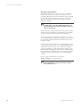
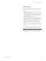
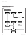
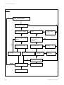
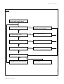
1
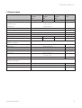
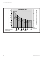
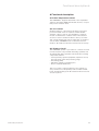
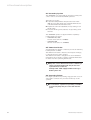
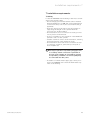
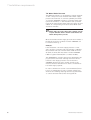
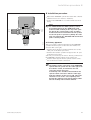
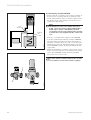
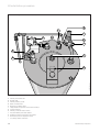
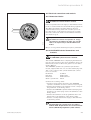
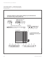
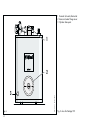
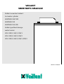
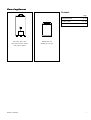
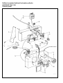
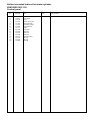
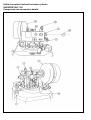
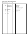
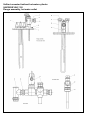
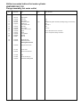
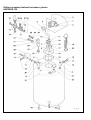
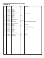
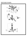
Installation Instructions
GB
Unvented hot water storage cylinders
for use with Vaillant boilers
Vaillant Vantage 120
Vaillant Vantage 150
Vaillant Vantage 200
2140100
ETC 00394
9411064
Contents
Page
1 Description . . . . . . . . . . . . . . . . . . . . . . . . .
2
2 Technical data . . . . . . . . . . . . . . . . . . . . . .
5
3 Dimensions . . . . . . . . . . . . . . . . . . . . . . . . .
7
4 Applications . . . . . . . . . . . . . . . . . . . . . . . . 10
5 Functional diagrams . . . . . . . . . . . . . . . . . .
11
5.1
5.2
11
Functional diagram of the primary circuit . . . .
Functional diagram of the secondary
connections . . . . . . . . . . . . . . . . . . . . . . . . . . . .
12
6 Functional description . . . . . . . . . . . . . . . . 13
6.1
6.2
6.3
6.4
6.5
6.6
D.H.W. Temperature Control . . . . . . . . . . . . . . .
C.H. Control . . . . . . . . . . . . . . . . . . . . . . . . . . . .
Primary Circuit . . . . . . . . . . . . . . . . . . . . . . . . . .
Secondary System . . . . . . . . . . . . . . . . . . . . . . .
Immersion Heater . . . . . . . . . . . . . . . . . . . . . . .
Secondary Return . . . . . . . . . . . . . . . . . . . . . . .
13
13
13
14
14
14
7 Installation requirements . . . . . . . . . . . . . . 15
7.1
7.2
7.3
7.4
7.5
7.5.1
Siting . . . . . . . . . . . . . . . . . . . . . . . . . . . . . . . . . . 15
Mains Water Pressure . . . . . . . . . . . . . . . . . . . . 16
Secondary System . . . . . . . . . . . . . . . . . . . . . . . 17
Pipework - Primary Circuit . . . . . . . . . . . . . . . . 18
Discharge Pipework . . . . . . . . . . . . . . . . . . . . . . 19
High Level Termination . . . . . . . . . . . . . . . . . . . 20
8 Installation procedure . . . . . . . . . . . . . . . . 21
8.1
8.2
8.3
8.4
8.4.1
8.4.2
Primary pipework . . . . . . . . . . . . . . . . . . . . . . . .
Secondary system Pipework . . . . . . . . . . . . . . .
Safety valve discharge pipework . . . . . . . . . . .
Electrical connections and controls . . . . . . . . .
Immersion Heater . . . . . . . . . . . . . . . . . . . . . . .
VANTAGE Electrical Connections
and Controls . . . . . . . . . . . . . . . . . . . . . . . . . . . .
8.4.3 Control options - system wiring scheme . . . . .
21
22
23
25
25
25
26
9 Commissioning . . . . . . . . . . . . . . . . . . . . . . 28
9.1
9.2
9.3
9.4
Filling Secondary D.H.W. Circuit . . . . . . . . . . . .
Filling the Primary Circuit . . . . . . . . . . . . . . . . .
Operating the Vaillant Boiler . . . . . . . . . . . . . .
User’s Instructions . . . . . . . . . . . . . . . . . . . . . . .
28
29
29
30
10 Maintenance . . . . . . . . . . . . . . . . . . . . . . . 31
11 Fault Finding . . . . . . . . . . . . . . . . . . . . . . . 32
We cannot accept responsibility for any damage which may occur as a result of non-observance of these
instructions. Subject to alteration.
2
Vaillant Vantage 120/150/200
Description 1
1 Description
The VANTAGE range of unvented hot water storage
cylinders are indirectly heated cylinders which are designed for use with Vaillant gas boilers only. The VANTAGE must NOT be installed with boilers supplied by any
other manufacturer.
VANTAGE cylinders are available in three sizes of 120,
150 and 200 litre nominal capacity. The cylinders are of
glass lined steel construction, insulated with CFC free
foam and enclosed in a decorative sheet metal casing.
They are supplied with all necessary cold and hot water
controls and are fitted with a mid position 3 port diverter valve for control of central heating and domestic hot
water.
The VANTAGE cylinders are prefitted with an operating
thermostat for controlling the water temperature.
VANTAGE cylinders are also provided with an auxiliary
back up electric immersion heater, including operating
thermostat and energy cut out.
The VANTAGE cylinders operate using a mains water
pressure supply and do not require a feed from a cold
water storage tank. The VANTAGE cylinders have 22 mm
D. H. W. outlet and cold water mains inlet connections
for optimum flow rate. To achieve optimum performance
from the VANTAGE an adequate cold water mains supply
pressure and flow rate must be available (see section
7.2: Mains Water pressure).
Vaillant Vantage 120/150/200
3
1 Description
Note To Installers
This product has been assessed and found to comply
with the requirements of the Building Regulations for
unvented hot water storage systems and must not be
altered or modified in any way.
The installation must be carried out by a competent person and be in accordance with the relevant requirements of the Local Authority, Building Regulations,
Building Standards (Scotland) Regulations and the byelaws of the local Water Undertaking. The installation is
subject to Building Regulation approval, notify the Local
Authority of intention to install. In the event of parts
replacement, use only genuine spare parts supplied by
Vaillant Ltd.
Check that the cylinder has been supplied with the following:
– Packed inside cylinder carton
Tundish, cylinder drain valve,
appliance top cover (including
operating thermostat), functional water controls pack,
installation and user instructions.
– Packed in separate carton
Expansion vessel (12 litre for
VANTAGE 120/150, 18 litre for VANTAGE 200).
Prior to installation, ensure that the VANTAGE cylinder
is stored upright in dry conditions. The VANTAGE must
be kept upright during transportation.
Please also refer to “General Requirements“ in the
installation instructions supplied with the Vaillant boiler.
4
Vaillant Vantage 120/150/200
Technical data 2
2 Technical data
Nominal storage capacity
Vantage
120
Vantage
150
Vantage
200
Unit
120
150
200
litres
Nominal DHW flow from
VANTAGE 120/150
15 l/min @ 60 °C
VANTAGE 200
20 l/min @ 60 °C
Maximum water supply pressure
10
bar
Maximum primary circuit pressure
2.5
bar
Expansion vessel charge pressure
4
bar
Operating pressure
3.5
bar
Net weight
70
82
101
kg
Weight (full)
190
232
301
kg
Cylinder connections:
Cold mains inlet
22 mm compression
D.H.W. outlet
22 mm compression
Balanced pressure cold water outlet
22 mm compression
Secondary return
G 3/4
Primary flow
22 mm compression
(on 3 port valve)
Primary return
22 mm compression
Electrical connections:
3 kW Immersion heater
230/240 V, 50 Hz
Three port valve
230/240 V, 50 Hz
Cylinder thermostat
230/240 V, 50 Hz
Vaillant Vantage 120/150/200
5
Vantage 200
60
50
40
50
Vantage 150
40
Vantage 120
30
30
20
20
10
10
8
THERMOcompact boiler
ecoMAX boiler
6
Note: Times shown for Vaillant boilers
assume no simultaneous heating demand
70
10
12
14
16
18
615 E
613/2 E
20
22
620 E
618/2 E
24
624 E
622/2 E
26
28 Heat input
to cylinder (kW)
628 E
VIH 380/2
Cylinder Heat Up Times
Reheat time for 70 % of cylinder contents (minutes)
Approximate cylinder heat up time - 15 °C to 65 °C (minutes)
2 Technical data
Vaillant Vantage 120/150/200
Dimensions 3
b
f
c
a
70
103
3 Dimensions
120
VIH 382/3 (Redesign)
e
d
170
127
Fig. 2 (all dimensions in mm)
a
b
c
d
e
f
Vantage 120
768
900
797
560
655
268
Vantage 150
961
1086
983
600
675
261
Vantage 200
1231
1356
1253
600
675
261
Vaillant Vantage 120/150/200
7
3 Dimensions
Boiler fitted directly above the cylinder
VIH 378/3 (Redesign)
A
B
C
D
Fig. 3
THERMOcompact and ecoMAX System boilers
THERMOcompact
ecoMAX
615 E, 620 E, 624 E, 628 E
613/2 E, 618/2 E, 622/2 E
Vantage cylinder
Vantage cylinder
120
1845
1910
150
2045
2110
200
2345
2410
120
A
2200
2200
150
B
2400
2400
200
2700
2700
C
305
240
D
145
190
Table 1
8
Vaillant Vantage 120/150/200
Dimensions 3
Vantage 120, 150, 200
A
H
C
B
F
E
I
D
VIH 360/0 (Redesign)
G
Fig. 4 Connection details
A
B
C
D
E
F
G
H
I
Primary flow from boiler
Heating flow
Primary return to boiler
Mains cold water inlet
Domestic hot water outlet
Temperature and pressure relief valve discharge
Sacrificial anode
Primary circuit air release valves
Secondary return connection
Vaillant Vantage 120/150/200
9
4 Applications
4 Applications
The Vaillant VANTAGE may only be connected to a
Vaillant boiler.
No other indirect heat source may be used.
The following Vaillant boilers are available for use with
the VANTAGE cylinders:
THERMOcompact system boilers
615 E (VU 152-5)
620 E (VU 202-5)
624 E (VU 242-5)
628 E (VU 282-5)
ecoMAX - Condensing system boilers
613/2 E (VU 126)
618/2 E (VU 196)
622/2 E (VU 246)
4.1 Typical applications
– Single bathroom property:
VANTAGE 120
– Single bathroom property with an en-suite shower
room:
VANTAGE 120 / 150
– Two bathroom property:
VANTAGE 150
– Two bathroom property with an en-suite shower room:
VANTAGE 150 / 200
– Larger properties:
VANTAGE 200
Commercial use: size depending upon hot water
requirements
Note:
1 Select the appropriate Vaillant boiler to match
the heating load (with the normal allowance for
heating up from cold) plus an allowance for
heating the hot water cylinder. Typically it is
practice to allow an additional 2-3 kW for the
hot water production.
2 Consideration should be given to the use of a
larger size of cylinder than shown above
where high water demands are likely.
10
Vaillant Vantage 120/150/200
Functional diagrams 5
5 Functional diagrams
5.1 Functional diagram of the primary circuit
1
3
A
B
4
2
D
5
VIH 362/2
C
Fig. 5
1
2
3
4
5
Vaillant boiler
VANTAGE cylinder
Circulating pump
3 port diverter valve
Immersion heater
A
B
C
D
Boiler flow
Boiler return
C/H flow
C/H return
Vaillant Vantage 120/150/200
11
5 Functional diagrams
5.2 Functional diagram of the secondary connections
5
B
1
3
A
C
6
2
E
D
VIH 363/2
4
Fig. 6
1
2
3
4
5
6
Temperature and pressure relief valve
Expansion relief valve combined with check valve
Pressure limiting valve combined with strainer
DHW thermostat pocket
Expansion vessel
Secondary return connection
A
B
C
D
E
Cold water mains inlet
Balanced pressure cold water outlet
DHW outlet
Tundish
Cylinder drain point
12
Vaillant Vantage 120/150/200
Functional description 6
6 Functional description
6.1 D.H.W. Temperature Control
The VANTAGE is supplied fitted with a user adjustable
domestic hot water (DHW) thermostat and also a 3 port
mid position diverter valve.
6.2 C.H. Control
Central heating is controlled by the fitted 3 port mid
position diverter valve in conjunction with suitable
external controls, such as a programmer, room thermostat or thermostatic radiator valves. The external
electrical controls should be wired to the 3 port valve
and cylinder thermostat in the normal way, as shown in
section 8.4.2, VANTAGE Electrical Connections and
Controls. No additional motorised valves are necessary.
6.3 Primary Circuit
The VANTAGE cylinder is provided for connection to the
flow and return of any Vaillant wall hung system boiler.
All Vaillant wall hung system boilers have the following
components built-in:
– Sealed primary system equipment (expansion vessel,
pressure relief valve and pressure gauge)
– Circulating pump
– Automatic primary system by-pass
– Boiler overheat thermostat
The 3 port valve is supplied fitted to the cylinder for
easy connection to the primary flow from the Vaillant
boiler, and the heating flow. No additional motorised valves are required.
Vaillant Vantage 120/150/200
13
6 Functional description
6.4 Secondary System
The VANTAGE is provided with all necessary safety and
control devices for unvented DHW operation.
These are as follows:
A A prefitted temperature and pressure relief valve
(90 °C, 7 bar) (An additional overheat thermostat is
contained within the Vaillant boiler).
B Expansion relief valve (6.0 bar) incorporating a non
return valve.
C Pressure limiting valve (3.5 bar) incorporating a line
strainer.
The VANTAGE cylinder is supplied with a separately
packed expansion vessel.
– VANTAGE 120 / 150:
12 Litre vessel (Art no. 2370051)
– VANTAGE 200:
18 Litre vessel (Art. no. 2370052)
6.5 Immersion Heater
A 3 kW immersion heater is fitted to provide an auxiliary
back-up means of DHW.
The immersion heater is fitted to the inspection flange,
located in the side of the cylinder.
The immersion heater is designed for use in unvented
installations and contains a safety overheat thermostat
in addition to the operating thermostat.
Note:
Only the correct immersion heater containing a
safety overheat thermostat may be used for
replacement (see table 2).
Vantage 120 - 200 equipped with heater type
Redring LU 11 TC.
6.6 Secondary Return
For larger systems incorporating long pipe runs a secondary return connection is provided on the top of the
cylinder.
Note:
A recirculation system incorporating a suitable
non ferrous pump may be connected into this
point.
14
Vaillant Vantage 120/150/200
Installation requirements 7
7 Installation requirements
7.1 Siting
Locate the VANTAGE in the building in the most convenient position ensuring that:
– The discharge pipe from the tundish can be installed
with a minimum fall of 1:200 and can be terminated in
a safe and visible position (see section 7.5 Discharge
pipework).
– The base chosen for the unit is level and capable of
supporting the weight of the cylinder when full
(see section 2: Technical Data).
– The installation site is frost-free. If necessary provide
a frost protection thermostat.
– Access is available for user operation of the DHW temperature control on the cylinder.
– Suitable clearances exist to allow installation, checking
and repressurising of the expansion vessel.
– The installation site chosen does not result in excessive ”dead leg” distances, particularly to the point of
most frequent use.
Note:
For larger systems incorporating long pipe runs
a secondary return connection is provided on
the top of the cylinder. A recirculation system
incorporating a suitable non ferrous pump may
be connected into this point.
– A suitable cold mains water supply pipe can be provided to the VANTAGE direct from the main water stop
valve of the building.
Vaillant Vantage 120/150/200
15
7 Installation requirements
7.2 Mains Water Pressure
The DHW performance of an unvented cylinder installation will correspond to the available mains water supply
pressure and flow rate. To achieve optimum performance from the VANTAGE a suitable cold mains water supply must be available, i. e. the measured static pressure
from the incoming mains water supply should be at least
2.0 bar. A corresponding flow rate at least 20-25 l/min
should be available.
Note:
Mains water pressures will reduce during periods
of peak demand. Ensure that measurements are
taken during these periods.
Once the available mains supply pressure and flowrate is
known the respective flowrate from the VANTAGE can
be obtained from fig. 7.
Example:
If the measured cold mains supply pressure is 2 bar
static and the cold mains flow rate available is 30 l/min,
the available flow rate of mixed water at 40 °C will be
25 l/min (from 15 l/min hot water from the VANTAGE
k 60 °C together with 10 l/min cold water @ 10°C).
The VANTAGE will operate satisfactorily with water supply pressures below 2 bar although flow rates will be
reduced. If the supply pressure is below 1 bar the
VANTAGE unvented storage cylinder should not be
installed. Contact Vaillant Ltd for details on alternative
hot water supply systems.
In order to minimise frictional losses minimum 3/4 inch
bore is recommended for new cold mains supply pipework into the dwelling although satisfactory performance can be achieved with 1/2 inch bore pipework.
16
Vaillant Vantage 120/150/200
Installation requirements 7
7.3 Secondary System
To achieve optimum distribution of the water supply it is
important that the water system pipework and
terminal fittings are correctly sized and balanced. The
teed-off supply to the bath outlet should be in 15 mm
pipework. The tee-offs to sinks and basins should be in
10 mm pipework. Terminal fittings should be suitable for
mains pressure operation and taps should be of the
aerated type to prevent splashing.
Flow rates from VANTAGE, hot 60 °C.
8 bar*
flow out (litres/min) of the system
40
4 bar*
3 bar*
2 bar*
30
1 bar*
Some designs of terminal fittings may allow excessive
flow rates resulting in user inconvenience and starvation
of other outlets. In these circumstances provide a valve
in the supply to that terminal fitting in order that the
flow rate can be regulated.
20
10
If the VANTAGE is being installed to existing pipework
with a 22 mm run to the bath terminal fittings and/or 15
mm to sinks/basins, an adjustable valve should be fitted
in the supply to each outlet: By adjustment of these valves, flow rates to fittings can be regulated to achieve
correct system balancing.
0
10
40
20
30
flow available (litres/min) at entry to system
Flow rates from VANTAGE, hot cold mixed.
flow out (litres/min) of the system
40
Mixed water @ 40 °C, mixed from
60 % hot water @ 60 °C and
40 % cold water @ 10 °C
8
4
3
2
bar*
bar*
bar*
bar*
If the water capacity of the additional secondary pipework exceeds
20 litres (VANTAGE 120 or 200) or
10 litres (VANTAGE 150) an
additional expansion vessel may be required.
1 bar*
30
Pipe capacities for copper tube are:
20
10
0
20
30
40
10
flow available (litres/min) at entry to system
2) the graph represents the results of tests carried out by the BBA and Vaillant.
3) where static water pressures are less than 1 bar, consult Vaillant Ltd.
* static supply pressure of incoming water supply.
VIH 364/1
Notes:
1) flow rates shown apply to situations where the supply is capable of supplying an adequate dynamic pressure.
15 mm
0.13 l/m
22 mm
0.38 l/m
28 mm
0.55 l/m
The cylinder may be drained completely for maintenance works via the drain valve (E, fig. 6) after first turning
off the water supply to the cylinder and opening the hot
draw off taps. Adequate access to the drain valve must
therefore be available.
Fig. 7
Vaillant Vantage 120/150/200
17
7 Installation requirements
7.4 Pipework – Primary Circuit
The primary circuit pipework
between the Vaillant boiler and the VANTAGE should be
installed using copper tube of minimum size 22 mm.
If the distance between the boiler and the cylinder is
excessive, a larger pipe diameter may be necessary. It is
not necessary to install a circulating pump in this pipework because all Vaillant wall mounted boilers contain a
built-in circulating pump.
With the VANTAGE connected to a Vaillant boiler the
remaining pump head available, at a flow rate
corresponding to 20 °C temperature difference, is given
in table 3.
System Pipework should be sized such that the resistance of the heating circuit offering the greatest resistance to flow (the index circuit) does not exceed this
figure.
18
Boiler
Pump head available to
heating circuit (m)
THERMOcompact 615 E
2,5
THERMOcompact 620 E
2,5
THERMOcompact 624 E
2,5
THERMOcompact 628 E
2,5
ecoMAX 613/2 E
2,5
ecoMAX 618/2 E
2,5
ecoMAX 622/2 E
2,5
Vaillant Vantage 120/150/200
Installation requirements 7
7.5 Discharge Pipework
The outlet connections of both the temperature and
pressure relief valve and expansion relief valve should
be connected in 15 mm copper tube to the tundish supplied.
The tundish should be installed vertically, as close to the
VANTAGE as possible and within 500 mm of the temperature and pressure relief and expansion relief valve outlets. It must be positioned away from any electrical components and installed in the same space as the
VANTAGE cylinder.
The discharge pipework must be installed using minimum 22 mm copper pipework from the 1" inch BSP
female connection on the tundish to a safe and visible
discharge point. There must be a vertical section of pipe
at least 300 mm long, below the tundish before any
bends or elbows in the pipework. Increase the diameter
of the pipework if the total resistance of the discharge
pipework exceeds the figures shown in table 4.
Minimum size
of discharge
pipework
from Tundish
Maximum total resistance Resistance created
allowed expressed as a
by each elbow
length of straight pipe
or bend
(i. e. no elbows or bends)
22 mm
up to 9 m
0.8 m
28 mm
up to 18 mm
1.0 m
35 mm
up to 27 mm
1.4 m
Example
22 mm discharge pipe having 4 elbows and a length of
7 m from the tundish to the discharge point:
Resistance for 4 elbows
at 0.8 m each
= 3.2 m
Resistance of discharge pipe = 7.0 m
Total Resistance
= 10.2 m
The total resistance of the discharge pipework is
greater than the maximum allowed for 22 mm
pipework (9 m). Therefore calculate the next largest
size.
28 mm discharge pipe with 4 elbows and 7 m length
from tundish to discharge point.
Resistance for 4 elbows
at 1.0 m each
= 4.0 m
Resistance of discharge pipe = 7.0 m
Total Resistance
= 11.0 m
The total resistance of the dischargepipework is less
than the maximumallowed for 28 mm pipework (18 m)
therefore the discharge pipework size is acceptable.
Vaillant Vantage 120/150/200
19
7 Installation requirements
Typical discharge pipe arrangement
metal discharge pipe from
temperature relief valve to tundish
safety
device
(e.g.
temperature
relief valve)
500 mm
maximum
tundish
Discharge below
fixed grating
300 mm
minimum
metal discharge pipe from tundish
with continuous fall. See 7.5
Table 4 and worked example
fixed grating
VIH 365/1
trapped gully
Under fault conditions, the discharge warning pipe can
emit water at near boiling temperature. Ensure the
discharge pipe terminates at a safe position where there
is no risk of contact with hot water by persons in or
about the building.
A suitable position for the discharge point is ideally
below a fixed grating and above the water seal in a
trapped gully. Downward discharges at low level, i. e. up
to 100 mm above external surfaces such as car parks,
hard standings, grassed areas, etc. are acceptable providing that where children may play or otherwise come
into contact with discharges a wire cage or similar guard
is positioned to prevent contact, whilst maintaining visibility.
Do not fit any valves or taps to the discharge pipework.
Ensure the pipework has at least 1:200 fall
continuously from the tundish to the discharge point.
The discharge pipe from the pressure relief valve of the
Vaillant boiler may be teed-into the discharge pipework
from the VANTAGE downstream of the tundish.
Fig. 8
7.5.1 High Level Termination
High level termination
tundish
300 mm
minimum
discharge pipe
X
Fig. 8a
20
VIH 372/1
X = diameter of
discharge pipe
Providing that the point of termination is such that persons in or around the building will not be endangered
should discharge take place, the method of termination
shown in fig. 8a is satisfactory. Examples of points to
consider when deciding whether a location for the high
level discharge is suitable are:
– The possibility, taking into account wind effect, that
someone may be in the path of the water being
discharged and if so, whether the temperature of the
discharge water will have been sufficiently reduced to
not be dangerous. Thermal conductivity of the structure’s surface, climatic conditions and location and orientation of the discharge pipe may or may not have
an effect on reducing the temperature of the discharge water.
– The location of windows and similar openings.
– The likelihood of a pram being left beneath the point
of discharge.
– The ability of the structures surface to withstand near
boiling water.
– The possibility of ice formation if water is discharged
onto pedestrian walkways.
Vaillant Vantage 120/150/200
Installation procedure 8
8 Installation procedure
• Unpack the VANTAGE cylinder and check the contents
(detailed in section 1: notes to installers).
• Position the VANTAGE in accordance with section 7.1:
Siting
W M H
´A´ Port
heating
flow
´AB´ Port
boiler flow
Fig. 9
VIH 366/1
´B´ Port
to
cylinder
Note:
For VANTAGE 150 and 200 cylinders, remove
the blanking plug from the DHW thermostat
pocket located centrally at the top of the cylinder. Uncoil the sensing probe of the operating
thermostat and insert it FULLY into the pocket.
Secure the probe in position by fitting the retaining clip supplied (the VANTAGE 120 thermostat
probe is factory fitted).
8.1 Primary pipework
The 3 port valve is supplied prefitted to the VANTAGE
cylinder. The three ports of the valve are marked ”A”,
”B” and ”AB” (see fig. 9).
• Connect the flow pipe from the Vaillant boiler to the
”AB” port of the three port valve.
• Connect the radiator system flow pipe to the ”A” port
of the three port valve.
(The ”B” port of the 3 port valve is already connected to
the VANTAGE cylinder primary flow connection).
• Install a return pipe from the cylinder return connection to the boiler return connection.
Note:
The primary return connection of the VANTAGE
cylinder must be joined into the return pipe from
the radiator circuit, and should be the last
connection before the boiler.
A balancing valve should be fitted between the
cylinder return connection and the return pipe
from the radiator circuit (see fig. 10). This valve
should be set to ensure correct primary flow
through the radiators and cylinder during simultaneous heating and hot water demand.
Vaillant Vantage 120/150/200
21
8 Installation procedure
8.2 Secondary system Pipework
• Connect the two cold water control valves together as
shown in fig 11., ensuring that the orientation of the
valves, when installed in the cold mains supply, allows
the 15 mm outlet of the expansion relief valve to be
connected to the tundish.
Note:
The Expansion relief / non return valve has a
R 3/4 connection, and is supplied fitted with a
PTFE ring to ensure a watertight seal when
screwed into the pressure limiting valve (separate instructions are supplied with the control valves).
3 port
diverter valve
Balancing
valve
position
VIH 367/1
• Provide a cold water mains supply to the VANTAGE.
•
Fig. 10
To ensure optimum performance from the VANTAGE,
and particularly in installations where the balanced
pressure cold water outlet (2, fig. 11) is to be used, the
pipework provided from the building mains stop valve
to the VANTAGE cylinder should be minimum 22 mm
copper tube.
Install the assembled cold water control valves (fig. 11)
in the cold mains supply at a convenient position adjacent to the VANTAGE cylinder, ensuring adequate
space exists for service access.
Important
No valve shall be installed between the assembled cold water control valves and the cylinder.
1
2
VIH 368/1
3
Fig. 11
22
Vaillant Vantage 120/150/200
Installation procedure 8
• Connect the expansion vessel to the installed water
controls by either:
i. Screwing the vessel directly into the control assembly at the purpose provided connection (3, fig. 11) or,
ii. Connecting the vessel to the control assembly via
copper pipe or a suitable approved flexible connection hose, ensuring that the vessel is adequately
supported.
Note:
An optional ”Remote Expansion Vessel Mounting
Kit” (Art no. 2378083) is available for use with
VANTAGE cylinders. The kit contains a wall
mounting bracket and a 1 metre flexible connection.
• Connect the balanced pressure cold water supply (if
required) to the pressure limiting valve.
Note:
In areas where the mains water pressure is high
(4 bar or above) the cold water supply to a bath
or shower mixer valve can be taken from the
balanced pressure cold water outlet (2, fig. 11) of
the cold water controls. This will ensure that
both hot and cold supplies to the mixer valve
are at approximately the same pressure. The
cold water supply for all other terminal fittings
should be teed into the cold water supply pipework to the VANTAGE upstream of the cold
water controls.
• Connect the DHW outlet pipework to the 22 mm
domestic hot water outlet on the VANTAGE (E, fig. 4).
Continue with 22 mm size pipe to the first tee fitting
after which 15 mm pipework should be adequate.
If the pipe runs are of excessive length or there are
several terminal fittings supplied, extend the length of
pipework in 22 mm. (See 7.3: Secondary System.)
8.3 Safety valve discharge pipework
• Connect the temperature/pressure relief and expansi-
on relief valves to the tundish and install the discharge
pipework from the tundish in accordance with section
7.5: Discharge Pipework.
Vaillant Vantage 120/150/200
23
8 Installation procedure
VANTAGE 120, 150 and 200 installation
D
C
J
B
A
H
K
L
F
I
E
VIH 374/0 (Redesign)
G
Fig. 12
A
B
C
D
E
F
G
H
J
K
L
I
24
Primary flow from boiler
Heating flow
Primary return to boiler
Main cold water inlet
Domestic hot water outlet
Temperature and pressure relief valve discharge
Sacrificial anode
Primary circuit air release valves
Pressure limiting valve and strainer
Combined expansion relief and check valve
Connection point for expansion vessel
Secondary return connection
Vaillant Vantage 120/150/200
Installation procedure 8
8.4 Electrical connections and controls
Immersion heater electrical connections
8.4.1 Immersion Heater
Warning:
The immersion heater must be earthed.
Install a separate electrical supply to the immersion heater in accordance with the current IEE wiring regulations
(BS 7671). The immersion heater must be wired in
2.5 mm2 heat-resisting cable from a double pole isolating switch. The circuit must be protected by a 13 amp
fuse. The connection details for the immersion heater
are shown in fig. 13.
L
E
N
C
T
N
VIH 370/1
E
Important:
The immersion heater incorporates an energy
cut-off device and must not under any circumstances be replaced by a standard immersion
heater.
Only a correct genuine Vaillant spare part is permitted.
Fig. 13
8.4.2 VANTAGE Electrical Connections and
Controls
Warning:
The VANTAGE cylinder must be eartherd.
The Vaillant VANTAGE and accompanying Vaillant boiler
may be controlled using various programmers and room
thermostats, details of which are given in section 8.4.3:
Control Options.
The VANTAGE cylinder has a prefitted cylinder thermostat, supplied with 1 m of 3 core and earth flying lead.
The colour coding for the cylinder thermostat connection is as follows:
Brown wire
Common
Blue wire
DHW calling
Black wire
DHW satisfied
Green / yellow wire Earth
Connections to wiring centre
• Provide a wiring centre adjacent to the VANTAGE
cylinder to make the electrical connections (see fig. 14).
• Connect the Vaillant boiler terminals to the corresponding terminals of the wiring centre.
• Connect the VANTAGE cylinder thermostat flying lead
and the 3 port valve flying lead to the terminals of the
wiring centre.
• Connect the terminals of the programmer and room
thermostat to the terminals of the wiring centre.
• Connect a 3 amp fused mains supply to the terminals
of the wiring centre.
NOTE:
All wiring must be carried out in accordance
with BS 7671: Requirements for electrical installations (IEE Wiring Regulations, 16th edition).
Vaillant Vantage 120/150/200
25
8 Installation procedure
8.4.3 Control options – system wiring scheme
Important 1-10 must go to the corresponding number in
the wiring centre.
Connection details for control systems utilising 3 port motorised valve
via external wiring centre/junction box
Diagram only applies to the specific controls mentioned
3 amp fused
main supply
THERMOcompact 600 series
ECOmax 600/2 series
terminal strip
L
N
L
N
3
4
5
L
N
L
N
3
4
5
Programmer
for programmer connections see fig. 15
External wiring centre/junction box*
N
N
L
L
3
4
5
6
7
8
9
10
*Do not use pre-wired printed circuit board type
Room thermostat
5
9
6
Vaillant VRT 30
5
4
3
3
1
N
3
L
Danfoss Randall RMT 230
4
2
1
Danfoss Randall RET 230
N
3
L
Grässlin Towerchron RS
4
2
3
3
1
1
4
3
1
2
1
E
E
Horstmann HRT 2
Siemens-Landys & Staefa RAD 1
BLACK
BLUE
Sunvic TLX 2000 series
4
1
3
Potterton PRT2
N
H
TL
E
E
5
EARTH
EARTH
BLUE
7
BROWN
L
CENTRAL
HEATING
ON
E
5
3
6
HOT
WATER
ON
HOT
WATER
OFF
7
8
E
ACL Drayton RTS 1, 2
Honeywell T6360
4
N
not used
ACL Drayton Digistat 1
8
E
9
BROWN
OR
WHITE
8
GREY
4
ORANGE
3 Port mid position motorised valve
Anschluss VIH Vantage 1
Vantage cylinder thermostat
If a room thermostat is not used,
terminals 6 and 9 of the wiring centre
must be linked
Fig. 14
26
Vaillant Vantage 120/150/200
Installation procedure 8
Connection details between programmer and wiring centre.
Lifestyle LP241, LP 522, LP 722
N
L
1
3
4
5
3
8 not used 7
6
E
N
L
1
3
4
5
3
8 not used 7
6
E
N
L
1
3
4
*
5
3
8 not used 7
6
N
L
1
3
4
5
3
8 not used 7
6
L
N
3
4
3
5
6
not used
N
L
1
3
4
5
3
8 not used 7
6
Horstmann Channel Plus H21, H27
Note:
*Earth not required,
Link L - 2 - 5
E
N
L
1
*
5
3
7
Siemens-Landis & Staefa RWB2, RWB9
N
L
1
3
4
5
3
8 not used 7
6
E
N
L
1
3
4
5
3
8 not used 7
6
Tempus 6, Tempus 7
Danfoss Randall CP 715, FP715
Note:
*Earth not required
Grässlin Towerchron QE2, QM2
Honeywell ST699B, ST799A
Note:
Link L - 5 - 8
Honeywell ST6200, ST6300, ST6400
Potterton Myson EP 2001, EP 3001, EP 6002
Note:
Link L - 5
2
2
2
2
2
5
2
2
6
7
7
8
3
4
8
6
N
L
1
3
4
5
3
8 not used 7
6
2
8
5
6
not used
5
Anschluss VIH Vantage 2
Sunvic Select 207
2
Fig. 15
Vaillant Vantage 120/150/200
27
9 Commissioning
9 Commissioning
9.1 Filling Secondary D.H.W. Circuit
Note:
Do not manually open the temperature and pressure relief valve or expansion relief valve for
venting purposes (any foreign matter in the
pipework may cause damage to the valve seats).
• Ensure that the cylinder drain valve (E, fig. 6) is clo•
•
•
sed.
Open all the hot and cold water taps or other terminal
fittings.
Open the mains water supply to the VANTAGE and
continue filling until water runs freely from the
terminal fittings, ensuring all air pockets are purged.
Close the terminal fittings and check the system for
leaks.
The system should now be thoroughly flushed.
• Open hot water taps at opposite ends of the system
•
28
and allow water to discharge for at least 5 minutes.
Close the hot water taps.
Commissioning 9
9.2 Filling the Primary Circuit
Note:
Do not use boiler pressure relief valve for venting purposes.
• The complete primary C.H. system must be flushed
•
•
•
•
•
out with both cold and hot water. Fill and vent the
central heating system as detailed in the boiler installation instructions.
To assist with this operation set the manual override
lever on the 3 port diverter valve (fig. 9) to the
MANUAL position, and lock in this position by pushing
the lever into the valve head.
Vent air from the VANTAGE heating coil from the venting points (H, fig. 4).
Completely drain the CH system, then refill and vent.
Reset the lever on the 3 port valve to the ”AUTO”
position by releasing the manual operating lever from
the valve head (pull outwards).
For commissioning purposes and to reduce the time
for the cylinder contents to reach temperature, set the
cylinder hot water thermostat knob to setting 3
(approx. 40 °C).
Operate the boiler as in section 9.3 until both the
cylinder has reached temperature and all radiators in
the system are hot. Then once again drain the
complete CH system to remove residues from the
pipework and refill and vent again as above.
Reset the manual operating lever on the 3 port valve
to the ”AUTO” position once the system has been
refilled and vented.
9.3 Operating the Vaillant Boiler
• Ensure the boiler mains switch is turned on.
• Ensure that the programmer and thermostats are calling for heat.
• Check that the boiler fires and heats the cylinder con•
•
Vaillant Vantage 120/150/200
tents and the radiators according to the DHW and
room thermostat settings.
Carry out the commissioning and testing procedures
detailed in the installation instructions supplied with
the Vaillant boiler.
Upon completion of the commissioning procedures,
set the DHW thermostat knob on the VANTAGE to setting 5-6, approx. 60 °C, and set the back up immersion heater (fig. 13) thermostat to 60 °C.
29
9 Commissioning
9.4 User’s Instructions
Hand the instructions for use to the user for retention
and instruct in the safe operation of the boiler and
cylinder. Advise the user of the operation of the cylinder
thermostat, and that normally a setting of 5-6, which
gives a stored water temperature of approximately
60 °C is adequate.
Note:
In hard water areas the DHW temperature setting should not exceed this setting to avoid possible scale build-up.
Advise the user of the precautions necessary to prevent
damage to the system and to the building if the system
does not remain operative during frost conditions.
Advise the user that the immersion heater is provided
as a back up means of water heating and is not intended
for use at the same time that the Vaillant boiler is heating the cylinder.
Finally, advise the user that for continued efficient and
safe operation, the Vaillant boiler and VANTAGE cylinder
should be serviced at least once a year by a qualified
servicing company. It is important and strongly recommended that arrangements are made for a maintenance
agreement with a qualified servicing company to ensure
regular servicing of the Vaillant boiler and VANTAGE
cylinder.
Please contact Vaillant Service Solutions
(0870 - 6060777) for further details.
Note:
Leave installation, servicing and user instructions with the user.
30
Vaillant Vantage 120/150/200
Maintenance 10
10 Maintenance
The following maintenance work has to be carried out
annually by the competent installer or Vaillant Service
Solutions.
• Inspection of pressure/temperature relief valve and
•
•
•
•
expansion relief valve.
Manually operate each valve by twisting the operating
cap, and check if water flows unobstructed via the tundish to the discharge point. Ensure that both valves
re-seat satisfactorily.
Check pressure of expansion vessel.
Turn off mains water supply and open nearest hot
water tap to depressurise the secondary water system.
Check the expansion vessel charge with a pressure
gauge at the test point. If the pressure is below
3.5 bar, top up with suitable air pressure pump.
Every 2 years check corrosion protection anode for
wear.
The anode has a life expectancy of approximately 6
years. It should be replaced if the diameter is less than
12 mm.
Servicing procedures for the Vaillant boiler are contained in the boiler installation and servicing instructions.
Note:
In the event that parts require replacement, use
only genuine spare parts supplied by Vaillant
Ltd.
Vaillant Vantage 120/150/200
31
11 Fault finding
11 Fault finding
Note:
Only genuine spare parts supplied
by Vaillant Limited must be used.
Fault A:
The water from the cylinder is cold.
Does boiler operate?
NO
Do external controls
function?
YES
Remedy fault
according to boiler
instructions.
NO
Remedy fault
according to controls
instructions.
YES
Is 3-port valve in
corect position? (Mid
or DHW position).
Does cylinder
thermostat operate?
NO
Replace cylinder
thermostat.
YES
Check/replace
3-port valve.
Vent heating coil of
air (H, fig. 4).
NO
Is operation now
OK?
YES
Fault remedied.
VIH_Fault_A
VIH_Fault_A
YES
NO
Fig. 16
32
Vaillant Vantage 120/150/200
Fault finding 11
Fault B:
Water discharging from expansion
relief valve.
Manually reset / seat expansion relief
valve. Is discharge still occuring?
NO
YES
Is the discharge occuring only when the
cylinder is being heated?
NO
YES
Check pressure
charge in expansion
vessel.
NOT OK
Reset pressure in
expansion vessel.
Does pressure hold?
Turn off boiler and
immersion heater. Is
discharge still occuring?
YES
OK
Exchange expansion
relief valve.
NO
YES
NO
Is pressure downstream
YES of pressure limiting valve
less than 3.5 bar?
NO
Exchange pressure
limiting valve.
Exchange
expansion vessel.
Is operation now
OK?
Fault remedied.
NO
VIH_Fault_B
YES
Fig. 17
Vaillant Vantage 120/150/200
33
11 Fault finding
Fault C:
Water discharging from temperature/
pressure relief valve (TPRV).
Manually reset the TPRV. Is
discharge still occuring?
NO
YES
YES Check temperature control
of boiler.
Is discharge occuring only
when the boiler is in use?
OK
NO
Is discharge occuring only
when the immersion heater
is in use?
Does 3-port valve change to
heating position when
cylinder reaches
temperature?
YES
NO
Check operation of
cylinder thermostat.
YES
Replace TPRV.
YES
NO
Are immersion heater
thermostat and cut out
faulty?
NO
NOT Remedy fault
OK according to boiler
instructions.
Replace cylinder
NOT thermostat.
OK
OK
Replace immersion heater.
Check operation of NOT Replace
3-port valve.
OK 3-port valve.
OK
NO
Is discharge still occuring?
YES
NOT OK
Is operation now OK?
Replace TRPV.
Fault remedied.
VIH_Fault_C
OK
Fig. 18
34
Vaillant Vantage 120/150/200
Fault finding 11
Fault D:
Deteriorating water pressure and flow
from hot water terminal fittings.
Check incoming main water pressure.
Poor
Inform customer to have water service
checked by water undertaker.
Dirty
Clean / replace strainer.
Faulty
Replace faulty valve.
OK
Check line strainer
(in pressure limiting valve).
OK
Check pressure limiting valve.
OK
Check sytem for blockage.
Blocked
Replace / clear blocked components.
OK
Symptoms still persisting?
YES
NO
Fault remedied.
VIH_Fault_D
Check system as for discharge from
temperature or expansion relief valve.
Fig. 19
Vaillant Vantage 120/150/200
35
83 39 21 GB01 • 12/2001 V • Subject to alteration • Printed in Germany
Head Office
Vaillant Ltd., Vaillant House,
Medway City Estate, Trident Close,
Rochester, Kent ME2 4EZ
Sales
Service Solutions
Technical Advice
Training
01634 292310
0870 6060 777
01634 292392
01634 292370
INSTRUCTIONS FOR USE
VAILLANT VANTAGE
UNVENTED HOT WATER CYLINDER
120 / 150 / 200
INTRODUCTION
Your Vaillant VANTAGE unvented hot
water cylinder and Vaillant boiler,
together provide you with a modern,
efficient, high performance heating and
hot water system.
Because your VANTAGE hot water
cylinder is supplied with water directly
from the mains, you get the benefit of
mains pressure hot water at your hot
taps, without the need for storage tanks
in the loft and without a hot water pump.
The VANTAGE is made from high quality
glass lined steel within an easy clean
casing. The cylinder is fully insulated
using CFC free foam insulation to help
keep your hot water running costs at a
minimum, and protect the environment!
Your VANTAGE cylinder is tailor made to
accompany a Vaillant boiler. All Vaillant
boilers are equipped with 'built-in'
energy saving technology, such as burner
modulation, anti cycling control and high
efficiency heat exchangers.
Please read these instructions carefully to
ensure that you get the very best out of
your Vaillant heating and hot water
system.
2
IMPORTANT NOTES
☞ Your VANTAGE unvented hot water
cylinder must be installed by a
competent person in accordance with
current Building Regulations. Do not
remove or adjust any component part
of this cylinder. In the unlikely event
that your VANTAGE develops a fault,
such as a flow of hot water from the
discharge pipe, switch the boiler and
immersion heater off and contact
Vaillant Ltd or your installer.
☞ The appliance must be earthed.
☞ If the VANTAGE is installed in a
cupboard used for airing purposes
please ensure that clothing or other
articles are not placed on the cylinder
or its associated controls.
☞ Access should always be maintained
to allow operation of the domestic hot
water thermostat control.
How to use your VANTAGE
hot water cylinder
Domestic hot water thermostat
6 78
Fig. 1
VIH 376/1
5
1 2
3 4
Your Vaillant boiler and VANTAGE
unvented hot water cylinder will provide
both central heating and mains pressure
hot water.
If a programmer has been fitted to control
the central heating and hot water, check
that this is set to the desired on and off
periods.
Check that the Vaillant boiler is
operational as detailed in the Instructions
for use supplied with the boiler.
The boiler will then operate automatically
to heat the cylinder contents at the
desired times to the temperature selected.
When domestic hot water is used, the
Vaillant boiler will operate to re-heat the
VANTAGE cylinder as required.
Rotate the domestic hot water thermostat
on the VANTAGE to the desired setting.
(Normally a setting of 5-6, which gives a
stored water temperature of
approximately 60 °C is adequate).
The electric immersion heater is provided
as a back up means of water heating
and is not intended for use at the same
time that the boiler is heating the
cylinder.
NOTE: In hard water areas the DHW
temperature selected should not exceed
this setting to avoid possible scale
build-up.
3
1 Domestic hot water thermostat.
2 Immersion heater flange cover.
3 Cylinder drain point.
1
3
Fig. 2
4
VIH 377/1 (Redesign)
2
Fig. 2 show the Vantage 150
IMPORTANT NOTES
Shutting down the VANTAGE
cylinder
Care and Maintenance
To shut down the heating and hot water
system for short periods, simply turn off
the Vaillant boiler as shown in the
instructions supplied with the boiler.
The casing of the VANTAGE cylinder may
be cleaned with a damp cloth and a little
soap. Do not use any abrasive or solvent
material which could damage the case or
fittings.
Frost protection
It is important that your VANTAGE hot
water cylinder and Vaillant boiler are
serviced annually by a competent person.
Please contact your installer or Vaillant
Service Solutions (0870 - 6060777) for
further details.
Please ensure that if you are absent
during a period of frost the central
heating system remains in operation and
the rooms and VANTAGE cylinder are
kept above freezing point. It must be
remembered however that the Vaillant
boiler will be automatically switched off
by built-in monitoring devices if certain
faults occur, e. g. interruption in the gas
or electricity supply.
Alternatively you can drain the central
heating system, Vaillant boiler and
VANTAGE cylinder.
5
Sales
01634 292310
Service Solutions 0870 6060 777
Technical Advice 01634 292392
Training
01634 292370
834032GB· 01/2000 V · GW-D · Subject to alteration
Head Office
Vaillant Ltd., Vaillant House,
Medway City Estate, Trident Close,
Rochester, Kent ME2 4EZ
VAILLANT
SPARE PART CATALOGUE
Vaillant unvented indirect
hot water cylinder
VANTAGE VIHC120
VANTAGE 120
VANTAGE 150, 200
Vaillant gas fired storage
water heater
VGH 130/1, 160/1, 190/1
VGH 130/2, 160/2, 190/2
VGH 130/3, 160/3, 190/3, 220/3
8026 97 GB 09/96
View of appliances
Content
Page
Vaillant gas fired
storage water heater
VGH 130/1, 160/1, 190/1
Vantage VIHC 120
VGH 130/2 Z, 160/2 Z, 190/2 Z
Vantage 120, 150, 200
3 - 11
Vaillant unvented indirect
hot water cylinder
13 - 25
Vaillant safety assembly
27 - 31
VGH 130/3 Z - 220/3 Z
Subject to alteration
1
Vaillant gas fired storage water heater
Page
Vaillant gas fired storage water heater
VGH 130/1, 160/1, 190/1
4-5
Vaillant gas fired storage water heater
VGH 130/2 Z, 160/2 Z, 190/2 Z
6-7
Vaillant gas fired storage water heater
VGH 130/3 Z, 160/3 Z, 190/3 Z, 220/3 Z
Subject to alteration
8 - 11
3
Vaillant gas fired storage water heater
VGH 130/1, 160/1, 190/1
4
Subject to alteration
Vaillant gas fired storage water heater
VGH 130/1, 160/1, 190/1
Pict.
No.
Article-No.
1
2
07-3998
15-3255
15-3256
15-3286
08-6104
19-1091
19-1090
19-1007
08-3851
28-5865
28-5867
draft diverter
guide plate
guide plate
guide plate
support
tube
tube
tube
tube
corrosion protection anode 1)
corrosion protection anode 1)
7
8
9
98-1745
08-2205
packingring
drain valve
gas section
10
11
12
14-3931
14-3930
13
14
15
16
17
18
19
20
05-1023
14-3942
17-0262
98-1765
08-0809
04-0248
08-4712
24-8305
24-8130
24-8330
24-8142
24-8340
24-8150
98-0424
12-6134
04-1449
04-3929
17-1170
18-2621
04-2843
04-2839
04-2914
08-8624
07-0413
3
5
6
21
22
23
24
25
26
27
28
29
30
Subject to alteration
Part
Indic.
VGH 130/1
VGH 160/1
VGH 190/1
VGH 130/1
not shown
VGH 130/1
VGH 160/1, 190/1·
1) Notice
All corrosion protection anodes have been changed in length +
depth from original specificacion
as shown no longer available,
please order part-no. 05-1023 (see pict.-no. 13)
knob
knob
magneto
gas section
knob
magneto
packingring
connection
test nipple
connection tube
burner nozzle
burner nozzle
burner nozzle
burner nozzle
burner nozzle
burner nozzle
packingring
spring
burner
pilot burner tube
thermo-couple
screw
pilot burner nozzle
pilot burner nozzle
pilot burner support
screw
cover plate
Type, Remarks
as shown no longer available,
please order part-no. 05-1023 (see pict.-no. 13)
with parts 14-16
3,05
1,30
3,30
1,42
3,40
1,50
VGH 130/1 natural gas
VGH 130/1 LP-gas
VGH 160/1 natural gas
VGH 160/1 LP-gas
VGH 190/1 natural gas
VGH 190/1 LP-gas
38
21
natural gas (jet number is not orifice size)
LP-gas (jet number is not orifice size)
5
Vaillant gas fired storage water heater
VGH 130/2 Z, 160/2 Z, 190/2 Z
6
Subject to alteration
Vaillant gas fired storage water heater
VGH 130/2 Z, 160/2 Z, 190/2 Z
Pict.
No.
Article-No.
1
07-3998
07-4923
15-3324
15-3326
15-3328
08-6104
-
draft diverter
draft diverter
flue baffle (spiral)
flue baffle (spiral)
flue baffle (spiral)
support
cover
07-1822
top cover
19-1091
19-1090
19-1007
19-1090
dip tube
dip tube
dip tube
dip tube for circulation
6
28-5865
28-5866
28-5867
corrosion protection anode 1)
corrosion protection anode 1)
corrosion protection anode 1)
7
8
9
10
11
12
13
08-2205
14-3942
05-1023
17-0262
98-1765
08-4712
24-8260
24-8270
24-8280
24-8130
24-8142
24-8150
98-0424
12-6134
04-1449
04-3929
17-1170
18-2621
04-2843
04-2839
04-2914
08-8624
09-1060
08-6335·
07-0334
17-7634
18-2618
09-0638
07-0463
drain valve
knob
gas section
magneto
packingring
connection tube
burner nozzle
burner nozzle
burner nozzle
burner nozzle
burner nozzle
burner nozzle
packingring
spring
burner
pilot burner tube
thermo-couple
screw
pilot burner nozzle
pilot burner nozzle
pilot burner support
screw
piezo ignition
support
screw
insulating tube
screw
ignition electrode
cover plate
2
3
4
5
5a
14
15
16
17
18
19
20
21
22
23
24
25
26
27
29
30
Subject to alteration
Part
Indic.
Type, Remarks
VGH 130/2-190/2 (push fit on flue duct, old type)
VGH 130/2-190/2(version with location push fit on top cover (new type)
VGH 130/2
VGH 160/2
VGH 190/2
960 mm
for VGH 130/2-190/2 with draft diverter
(push fit on flue duct) no longer available. substitute:
top cover 07-1822 and draft diverter 07-4923 (pict-no. 1)
VGH 130/2-190/2
(new model with draft diverter
located on top cover
VGH 130/2 (for cold water connection)
VGH 160/2 (for cold water connection)
VGH 190/2 (for cold water connection)
for VGH 130/2 shorten to 700 mm
for VGH 160/2 shorten to 800 mm
VGH 130/2
VGH 160/2
VGH 190/2
1) Notice
All corrosion protection anodes have been changed in length +
depth from original specificacion
with parts 13-15
2,60
2,70
2,80
1,30
1,42
1,50
VGH 130/2-190/2
VGH 130/2 natural gas
VGH 160/2 natural gas
VGH 190/2 natural gas
VGH 130/2 LP-gas
VGH 160/2 LP-gas
VGH 190/2 LP-gas
VGH 130/2-190/2
38
21
natural gas (jet number is not orifice size)
LP-gas (jet number is not orifice size)
beige
VGH 130/2-190/2
7
Vaillant gas fired storage water heater
VGH 130/3 Z, 160/3 Z, 190/3 Z, 220/3 Z
8
Subject to alteration
Vaillant gas fired storage water heater
VGH 130/3 Z, 160/3 Z, 190/3 Z, 220/3 Z
Pict.
No.
Article-No.
1
2
3
07-4923
08-6104
15-3391
15-3393
15-3395
15-3328
19-1091
19-2982
19-1090
19-2981
19-1007
19-2980
19-2955
19-2983
19-1091
19-2982
19-1090
19-2981
19-1007
19-2980
19-2955
19-2983
28-5866
28-5867
28-5868
28-5869
draft diverter
support
flue baffle (spiral)
flue baffle (spiral)
flue baffle (spiral)
flue baffle (spiral)
dip tube
dip tube
dip tube
dip tube
dip tube
dip tube
dip tube
dip tube
dip tube
dip tube
dip tube
dip tube
dip tube
dip tube
dip tube
dip tube
corrosion protection anode 1)
corrosion protection anode 1)
corrosion protection anode 1)
corrosion protection anode 1)
08-2205
07-1931
05-1023
14-3942
17-0262
98-1765
08-4733
98-0214
09-1060
08-0364
24-8240
24-8260
24-8260
24-8280
24-8132
24-8138
24-8142
24-8142
98-0424
04-1684
12-6134
16-1207
07-0482
23-5715
04-2961
07-0489
11-9105
07-0334
09-0668
11-9104
drain valve
adjusting screw
gas section
knob
magneto
packingring
connection tube
packingring
piezo ignition
hose
burner nozzle
burner nozzle
burner nozzle
burner nozzle
burner nozzle
burner nozzle
burner nozzle
burner nozzle
packing ring
burner
spring
inspection glass
cover plate
screw
pilot burner
cover plate
screw
screw
ignition electrode
screw
4
5
6
7
8
9
10
11
12
13
13a
14
15
16
17
18
19
20
21
22
23
23a
24
25
26
27
Subject to alteration
Part
Indic.
Type, Remarks
VGH 130/3
VGH 160/3
VGH 190/3
VGH 220/3
VGH 130/3, length of 800 mm, ø 20 mm
VGH 130/3, length of 800 mm, ø 18 mm
VGH 160/3, length of 960 mm, ø 20 mm
VGH 160/3, length of 960 mm, ø 18 mm
VGH 190/3, length of 1190 mm, ø 20 mm
VGH 190/3, length of 1190 mm, ø 18 mm
VGH 220/3, length of 1460 mm, ø 20 mm
VGH 220/3, length of 1460 mm, ø 18 mm
VGH 130/3, length of 800 mm, ø 20 mm
VGH 130/3, length of 800 mm, ø 18 mm
VGH 160/3, length of 960 mm, ø 20 mm
VGH 160/3, length of 960 mm, ø 18 mm
VGH 190/3, length of 1190 mm, ø 20 mm
VGH 190/3, length of 1190 mm, ø 18 mm
VGH 220/3, length of 1460 mm, ø 20 mm
VGH 220/3, length of 1460 mm, ø 18 mm
VGH 130/3, length of 855 mm
VGH 160/3, length of 970 mm
VGH 190/3, length of 1080 mm
VGH 220/3, length of 1200 mm
1) Notice
All corrosion protection anodes have been changed in length +
depth from original specificacion
with parts 10 - 12
2,40 mm
2,60 mm
2,60 mm
2,80 mm
1,32 mm
1,38 mm
1,42 mm
1,42 mm
ø
ø
ø
ø
ø
ø
ø
ø
VGH 130/3 natural gas
VGH 160/3 natural gas
VGH 190/3 natural gas
VGH 220/3 natural gas
VGH 130/3 LP-gas
VGH 160/3 LP-gas
VGH 190/3 LP-gas
VGH 220/3 LP-gas
VGH 130/3 natural gas, LP-gas
with pieces 24, 26, 27
for pilot burner LP-gas
9
Vaillant gas fired storage water heater
VGH 130/3 Z, 160/3 Z, 190/3 Z, 220/3 Z
10
Subject to alteration
Vaillant gas fired storage water heater
VGH 130/3 Z, 160/3 Z, 190/3 Z, 220/3 Z
Pict.
No.
Article-No.
28
04-2882
04-2881
04-3951
17-1174
07-2355
08-8624
07-1880
07-1880
07-1899
13-9419
98-0936
08-9317
08-9323
28-4049
11-6480
20-3841
07-6228
29
30
31
32
33
35
36
37
38
39
40
41
Subject to alteration
Part
Indic.
Type, Remarks
pilot burner nozzle
pilot burner nozzle
pilot burner tube
thermo-couple
cap
screw
cover
cover
cover
plug
packingring
flange
flange
disc
screw
cap
insolation
0,35 mm ø
0,20 mm ø
natural gas
LP-gas
M10X35mm
VGH 130/3 - 190/3 without cleaning flange, till 03.91
VGH 130/3 - 220/3 with cleaning flange, from 03.91
VGH 220/3 without cleaning flange, till 03.91
inspection hole VGH 220/3
VGH 220/3
VGH 220/3
VGH 220/3
VGH 220/3
VGH 220/3
VGH 220/3
VGH 220/3, not shown
11
Vaillant unvented indirect hot water cylinder
Page
Vaillant unvented indirect hot water cylinder
VANTAGE VIHC 120
14 - 15
Vaillant unvented indirect hot water cylinder
VANTAGE VIHC 120
Control panel
16 - 17
Vaillant unvented indirect hot water cylinder
VANTAGE VIHC 120
Component and connection details
18 - 19
Vaillant unvented indirect hot water cylinder
VANTAGE VIHC 120
Flange assembly, hot water outlet
20 - 21
Vaillant unvented indirect hot water cylinder
VANTAGE 120
22 - 23
Vaillant unvented indirect hot water cylinder
VANTAGE 150, 200
24 - 25
Subject to alteration
13
Vaillant unvented indirect hot water cylinder
VANTAGE VIHC 120
14
Subject to alteration
Vaillant unvented indirect hot water cylinder
VANTAGE VIHC 120
Pict.
No.
Article-No.
1
2
3
4
5
6
7
8
9
10
11
12
13
14
15
45-9886
08-2205
28-5847
98-0910
11-6480
28-4049
08-0408
17-7507
16-0029
08-5114
98-0325
06-0051
08-5014
05-0714
25-5008
25-5018
16-3489
25-5907
16
17
Subject to alteration
Part
adjusting screw
drain valve
protection anode
flange gasket
screw
disc
flow tee piece
air vent
sleeve nut
union connection
sealing ring
air vent
connector
3 port valve
motor
motor
elbow
cable tree
Indic.
Type, Remarks
M 10 X 35 mm
M 10
1" X 40 mm
with part 28
execution A, screwed to base plate
execution B, riveted to base plate
15
Vaillant unvented indirect hot water cylinder
VANTAGE VIHC 120
Control panel
16
Subject to alteration
Vaillant unvented indirect hot water cylinder
VANTAGE VIHC 120
Control panel
Pict.
No.
Article-No.
4
5
6
7
8
9
10
11
12
13
14
15
16
17
18
19
06-0018
13-0327
23-5748
07-5485
10-1804
10-1534
14-3950
25-1777
20-1623
25-0763
25-0762
25-5908
08-4471
25-2780
25-0790
12-0065
Subject to alteration
Part
Indic.
Type, Remarks
screw
circuit board
screw
control box housing
DWH thermostat
temperature gauge
thermostat knob
switch
cover plate
cable tree
cable tree
cable tree
connection cable
link plug
link plug
grommet
17
Vaillant unvented indirect hot water cylinder
VANTAGE VIHC 120
Component and connection details
18
Subject to alteration
Vaillant unvented indirect hot water cylinder
VANTAGE VIHC 120
Component and connection details
Pict.
No.
Article-No.
5
2378096
2378096
2370033
cu75 control valve type A
cu75 control valve type B
discharge pipework type A
discharge pipework type B
14
12370051
06-4505
2370009
2370010
2370013
2370016
2370015
expansion vessel
immersion heater
elbow
adaptor
expansion valve
expansion valve
temperature and pressure relief valve
15
2370011
line strainer
7
8
9
10
13
Subject to alteration
Part
Indic.
1)
1)
UI 9TC
6 bar
6 bar
7 bar
Type, Remarks
with lever PRV
with blue twist cap PRV
with tundish 13-7508
with tundish 13-7508
1) identificacion of item:
The connection between the T & P valve and
expansion relief valve to the discharge pipework has a:
Type A 3/4" flat washer union connection.
Type B 15 mm compression fitting connection.
supplied with gasket 2370072
3/4" MF (order as a pair)
3/4" MF (order as a pair)
type A with lever
type B with blue twist cap
with compression fitting connection
19
Vaillant unvented indirect hot water cylinder
VANTAGE VIHC 120
Flange assembly, hot water outlet
20
Subject to alteration
Vaillant unvented indirect hot water cylinder
VANTAGE VIHC 120
Flange assembly, hot water outlet
Pict.
No.
Article-No.
-
2370034
2
5
6
9
13
14
15
18
22
23
24
26
27
98-0910
2370003
2370004
06-4505
2370073
2370007
2370008
2370012
2370006
2370014
2370002
2370005
2370041
flange gasket
union nut
union piece
immersion heater
sealing ring
cu75 control valve
equal tee
union nipple
hot water outlet tee connection
nipple
nipple
T & P adapter
upstand
union nut
30
34
2370054
2370040
flange allen bolt
thermostat pocket
the following pieces are not shown
2370059
flange gasket aluminium washer
19-1091
2370031
cold water inlet tube
expansion vessel saddle bracket
13-7508
12-4850
2370072
tundish
thermostat phial retaining clip
immersion heater gasket
Subject to alteration
Part
Indic.
flange complete
Type, Remarks
with parts 1, 5-15
UI 9TC
3/4"
3/4"
supplied with gasket 98-9320 (including energy cut out device)
3/4"
see page 7
3/4"
1" X 3/4"
3/4" for flat washer union connection
3/4" for compression fitting connection
1"
21
Vaillant unvented indirect hot water cylinder
VANTAGE 120
22
Subject to alteration
Vaillant unvented indirect hot water cylinder
VANTAGE 120
Pict.
No.
Article-No.
1
2
3
4
5
6
7
8
9
10
11
12
13
14
15
16
17
19
20
21
22
23
24
25
26
27
28
29
30
31
32
33
34
35
36
37
-
11-4261
06-0009
07-2385
20-3887
10-1819
06-0520
18-3563
49-2109
17-7507
13-6382
98-0603
11-1244
98-0910
08-9386
08-3366
19-2985
49-0172
06-4505
2370072
20-3842
28-5859
08-3408
98-0410
11-1328
01-4610
12-9240
13-6384
20-3930
08-4968
07-6091
08-2205
07-1931
14-9108
14-9109
15-0228
19-0709
18-9312
13-7508
Subject to alteration
Part
Indic.
thermostat knob
screw
M 4 X 12 mm
cover plate
insulation cap
thermostat
thermostat pocket
thermostat retaining clip
tee-piece
de-aeration screw
union nipple
packingring
ø 22 mm
sleeve nut
packingring
flange
connection tube
cold water inlet dip tube
screw
M 10 X 35 mm
immersion heater
UI 9TC
immersion heater gasket
cap
corrosion protection anode
union nipple
packingring
ø 15 mm
sleeve nut
temperature/ pressure relief valve
9" probe
tee-piece
union nut
3 port valve
connection tube
cover plate
drain valve
adjustable screw feet
pressure reducing valve
0,5-6 bar
pressure reducing valve inset
0,5-6 bar
6 bar
safety valve
safety valve inset
6 bar
expansion vessel
12 litre
tundish
Type, Remarks
Rp 1 x Rp 1 x Rp 1/2
with part 20 (including energy cut out device)
for corrosion protection anode
with parts 24, 25
with parts 23, 24, 25
Rp 3/4 X Rp 3/4 X Rp 1/2 (red brass)
with parts 11, 12
with part 35
with part 37
not shown
not shown
23
Vaillant unvented indirect hot water cylinder
VANTAGE 150, 200
24
Subject to alteration
Vaillant unvented indirect hot water cylinder
VANTAGE 150, 200
Pict.
No.
Article-No.
1
2
3
4
5
6
8
9
10
11
12
13
14
11-4261
06-0009
17-8463
10-1819
06-0627
13-7293
49-2109
17-7507
13-6382
98-0603
11-1244
13-6380
19-3039
19-3040
20-3930
20-3842
28-5863
28-5864
01-4610
08-3408
98-0410
11-1328
08-4968
12-9240
13-6384
07-6113
20-3885
07-6388
13-0005
06-4506
2370072
11-6480
08-9387
98-0910
16-4340
15-8213
08-2205
07-1931
14-9108
14-9109
15-0228
19-0709
2370051
2370052
13-7508
15
16
17
18
19
20
21
22
23
24
25
26
27
28
29
30
31
33
34
35
36
37
38
39
40
41
-
Subject to alteration
Part
Indic.
thermostat knob
screw
M 4 x 12 mm
cover plate
thermostat
thermostat pocket
thermostat retaining clip
tee-piece
de-aeration screw
union nipple
packingring
ø 22 mm
sleeve nut
union nipple
cold water inlet dip tube
850 mm
cold water inlet dip tube
1100 mm
3 port valve
cap
corrosion protection anode
corrosion protection anode
temperature/ pressure relief valve
9" probe
union nipple
packingring
ø 15 mm
sleeve nut
connection tube
tee-piece
union nipple
cover plate
cover
insulation cap
screw
immersion heater
LUIITC
immersion heater gasket
screw
M 10 X 35 mm
flange
flange gasket
distance ring
nut
drain valve
adjusting screw
pressure reducing valve
0,5-6 bar
pressure reducing valve inset
0,5-6 bar
6 bar
safety valve
safety valve inset
6 bar
expansion vessel
12 litre
expansion vessel
18 litre
tundish
Type, Remarks
Rp 1 X Rp 1 X Rp 1/2
VIHC 150
VIHC 200
with parts 11, 12
VIHC 150
VIHC 200
with parts 19, 20, 21
Rp 3/4 X Rp 3/4 X Rp 1/2 (red brass)
with part 30 (including energy cut out device)
for flange gasket, not shown
with part 39
with part 41
VIH 150 (not shown)
VIH 200 (not shown)
not shown
25
Vaillant safety assembly
Page
Vaillant hot water storage heater
Safety assembly acc.-no. 695, 696
28 - 29
Vaillant hot water storage heater
Safety assembly acc.-no. 660, 661
30 - 31
Subject to alteration
27
Vaillant hot water storage heater
Safety assembly acc.-no. 695, 696
28
Subject to alteration
Vaillant hot water storage heater
Safety assembly acc.-no. 695, 696
Pict.
No.
Article-No.
1
2
3
4
5
6
7
8
19-0707
11-1369
98-0438
08-1625
98-0151
14-9104
13-7508
Part
safety assembly, cpl.
safety valve
sleeve nut
packingring
connection piece
packingring
pressure reducing valve
tundish
Indic.
Type, Remarks
see acc.-no. 660, 661 in valid appliance list
6 bar
with parts 3, 4
Notice
acc.-no. 660 for pressure under 6 Bar
acc.-no. 661 for pressure over 6 Bar
Subject to alteration
29
Vaillant hot water storage heater
Safety assembly acc.-no. 660, 661
30
Subject to alteration
Vaillant hot water storage heater
Safety assembly acc.-no. 660, 661
Pict.
No.
Article-No.
1
2
3
4
5
6
7
8
9
10
11
13
14
15
16
08-1625
98-0197
98-0223
01-0050
13-7508
13-7291
98-1605
95-0057
14-3981
13-7298
19-0709
19-0707
11-1228
11-1369
98-0438
13-7513
14-9106
-
17
18
19
20
Subject to alteration
Part
safety assembly, cpl.
connection piece
packingring
packingring
screw
tundish
packingring
plug
packingring
upper part of valve
knob with screw
knob
plug
safety valve inset
safety valve
sleeve nut
sleeve nut
packingring
tundish
pressure reducing valve inset
valve case
Indic.
Type, Remarks
see acc.-no. 660, 661 in valid appliance list
R 3/4
single delivery not possible
as shown no longer available, please order part-no. 95-0057 (see pict.-no. 9)
6 bar
6 bar, with parts 16, 17
R 1/2
R 3/4
single delivery not possible, available with acc.-no 661
Notice
acc.-no 660 for pressure under 6 bar
acc.-no. 661 for pressure over 6 bar
31