1
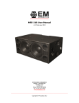
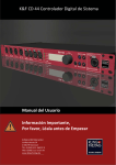
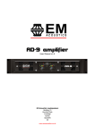
MSE-218SP User Manual
v1.1 February 2013
EM Acoustics Loudspeakers
Building 74, Dunsfold Park
Cranleigh, Surrey
GU6 8TB, UK
Phone +44 (0) 1483 266520
Fax +44 (0) 1483 275619
www.emacoustics.co.uk
_____________________________________________________________________________
Copyright EM Acoustics 2013
Page 2 of 20
Contents
Declaration of Conformity
Page 3
Safety Instructions
Page 4
1.0 - Introduction
Page 7
2.0 – The MSE-218SP Loudspeaker
Page 8
3.0 – Mains Power Requirements
3.1 – Power Supply
3.2 – AC input connector
3.3 – AC output connector
3.4 – Looped Mains connections
3.5 – Powering Up
Electrical Safety Issues
Page
Page
Page
Page
Page
Page
Page
9
9
9
9
9
10
10
4.0 – Amplification and Audio
4.1 – Audio Inputs
4.2 – Linking Audio Signals
4.3 – DSP Menu Structure
4.4 – Remote Monitoring & Control
Page
Page
Page
Page
Page
11
11
12
12
13
5.0 – MSE-218SP subwoofers in use
5.1 – System Overview
5.2 – Stacking
5.3 – Cardioid Arrays
5.4 – Mounting fullrange products
Page
Page
Page
Page
Page
14
14
14
14
14
6.0 - Servicing Information
Page 15
Appendix A – Technical Specifications
Page 16
Appendix B – Spare Parts
Page 18
Appendix C – Warranty Information
Page 19
MSE-218SP User Manual
v1.1 February 2013
Page 3 of 20
DECLARATION OF CONFORMITY
The product contained within this manual conform to the
requirements of the EMC Directive 89/336/EEC, amended by
92/31/EEC and 93/68/EEC, and to the requirements of the Low
Voltage Directive 73/23/EEC amended by 93/68/EEC.
Products Covered:
MSE-218SP
EMC Emission
EN55103-1:19961
Immunity
EN55103-2:19962
Electrical Safety
EN60065:2002
Notes:
1.This device may not cause harmful interference.
2.This device must accept any interference received, including interference that
may cause undesired operation.
RECYCLING
This product and its packaging constitute the applicable product according
to the WEEE directive. Please ensure that at the end of the working life of
this product, it is disposed of sensibly in accordance with local and national
recycling regulations. The packaging supplied with this product is
recyclable. Please retain all packaging, however if disposing of this
packaging please ensure that you comply with local recycling regulations.
These products also all comply to the RoHS Directive 2002/95/EC.
MSE-218SP User Manual
v1.1 February 2013
Page 4 of 20
IMPORTANT SAFETY INSTRUCTIONS
Please read these instructions completely before use.
Please keep the user manual in a safe place during the lifetime of the product - the
user manual forms an integral part of the product.
Heed all warnings.
Follow all instructions.
Do not use this product near water (for example, in damp rooms or near a
swimming pool).
Clean only with a dry cloth.
Do not cover or obstruct the heatsink – install this product only in accordance with
the instructions in this manual.
Do not install near heat sources such as radiators, heat registers, stoves or other
apparatus that produce heat.
Protect the power cable from being walked on, pinched or damaged in any way.
Pay particular attention to plugs and the point where they exit the loudspeaker.
This product may only be used in accordance with the information provided within
this manual. Before and during the usage of this product please ensure that all
recommendations, especially those relating to electrical safety, are adhered to.
The loudspeaker can only be disconnected from the power supply by removing the
plug, which must remain freely accessible at all times.
Unplug the loudspeaker from the mains power supply during electrical storms or
when unused for long periods of time.
Disconnect the mains plug before disconnecting the power cable from the
loudspeaker.
Refer all servicing to qualified personnel.
Servicing is required when:
o The power supply cable has been damaged
o Liquid has been spilled into the loudspeaker
o The loudspeaker has been exposed to rain or moisture
o The loudspeaker has been dropped or suffered damage in any way
o The loudspeaker exhibits a distinct change from its normal function or
performance for undetermined reasons.
SERVICING
Do not attempt to service this product yourself. Opening or removing covers may expose
you to dangerous voltages or other hazards – the amplifier module should only be opened
by qualified personnel. Please refer any service issues to your local EM Acoustics
representative. Upon completion of any service or repairs to this product, please ensure
your dealer or distributor has performed safety checks to determine the loudspeaker is in
proper operating condition.
ENVIRONMENTAL USE
Use this product only in E1, E2, E3 or E4 environments according to EN55103-2
“Electromagnetic compatibility – product family standard for audio, video, and audio-visual
and entertainment lighting control apparatus – Part 2: Immunity”.
MSE-218SP User Manual
v1.1 February 2013
Page 5 of 20
VENTILATION AND HEAT SINK
The heatsink and cooling fans are provided to ensure reliable operation of the
loudspeaker, and to protect it from overheating. The heatsink and fans must not be
blocked or covered. This product should only be installed with adequate ventilation
around the rear of the unit.
WATER AND MOISTURE
Do not use this product anywhere near water, or place any liquid-containing-vessels near
to the unit where spillage could occur.
CLEANING
Clean the loudspeaker only with a dry cloth. Disconnect the loudspeaker from the mains
before cleaning. Do not use liquid or aerosol cleaners.
POWER CABLE PROTECTION
Power supply cables should be routed so that they are not likely to be walked upon,
pinched or damaged by items placed upon or against them. Pay particular attention to
cables and plugs where they connect to the mains supply and to the loudspeaker itself.
LIGHTNING
For added protection of the product during lightning storms, or when it is left unattended
and unused for long periods of time, disconnect it from the mains supply. This will
prevent damage due to lightning and power line surges. Disconnection from the mains
power supply can only be achieved by removing the plug from the mains socket and by
external disconnection of all poles from the mains.
INTERFERENCE OF EXTERNAL OBJECTS AND/OR LIQUIDS
Never push any object of any kind into this product through its openings as they may
touch dangerous voltage points or short out parts that could result in a fire or electric
shock. Never spill liquid of any kind on the loudspeaker.
ACCESSORIES
Only use accessories supplied by EM Acoustics specifically for use with this product.
Unsuitable accessories for mounting or flying this loudspeaker could fail, causing serious
physical injury and/or damage to the loudspeaker.
CONNECTIONS
When connecting this product, perform all connections before connecting the unit to the
mains power. Failure to do so may cause electric shock and serious personal injury and/or
damage to the loudspeaker.
MAINS POWER PRECAUTIONS
When mounting or connecting this product, always disconnect it from the mains supply.
Only connect the product to an appropriate AC circuit and outlet, according to the
requirements stated on the panel on the rear of the loudspeaker.
If a power cut occurs when the unit is switched on, it will restart automatically once the
power supply is restored. All settings prior to the loss of power will be maintained.
MSE-218SP User Manual
v1.1 February 2013
Page 6 of 20
IMPORTANT: Always connect the product to the mains using the blue PowerCON MAINS
IN connector.
IMPORTANT: Only connect additional products to the white PowerCON MAINS LINK
connector, keeping within the specified current rating.
IMPORTANT: When disconnecting this product from mains power, always disconnect the
mains end first before disconnecting the PowerCON connector. Similarly, when connecting
this product always connect to the loudspeaker first, before applying mains power at the
supply.
ONLY CONNECT THIS PRODUCT TO MAINS POWER USING THREE CORE MAINS
POWER CABLE WITH A SUITABLE GROUNDING CONNECTION. REMOVAL OF
THE GROUNDING CONNECTION IS EXTREMELY DANGEROUS AND MAY
VIOLATE LOCAL ELECTRICAL CODES OF CONDUCT.
MSE-218SP User Manual
v1.1 February 2013
Page 7 of 20
1.0 - Introduction
Thank you for purchasing the MSE-218SP self-powered subwoofer from EM Acoustics.
The MSE-218SP has been designed and rigorously tested to give you the utmost in sonic
performance and many years of reliable, trouble-free operation. Please take the time to
read this user manual thoroughly to ensure you get the best performance from your
system and to ensure you set it up correctly and safely. If you have any questions or are
in any doubt whatsoever about any aspect of your new system, please do not hesitate to
contact us directly or your local EM Acoustics representative.
The MSE-218SP is one of the most accurate and powerful reflex subwoofers on the market
today. The marriage of the utmost in drive unit technology with a state-of-the-art
amplifier and control electronics package creates an ideal solution to a variety of
applications. MSE-218SP loudspeakers can be deployed in a wide range of professional
audio applications and will deliver stunning results time after time. Added to this is the
one-to-one customer support that EM Acoustics is known for and you should be
congratulated for purchasing one of the finest loudspeaker products on the market today.
This manual contains all the information you should need on topics of set up, connection,
flying & stacking and basic service. If you feel we have missed anything, or you have a
question not covered by this manual, please visit our website www.emacoustics.co.uk and
send us a message or give us a call – we’re only too happy to help.
Unpacking
Please take care when unpacking your loudspeaker system. Once unpacked, please
inspect each enclosure thoroughly for any transit damage and in the case of any damage
please notify your carrier immediately. It is the responsibility of you, the consignee , to
instigate any claim. Please retain all original packaging in case of future re-shipment.
System Setup
Professional loudspeaker systems are potentially dangerous objects if used incorrectly.
Please ensure that you read this section fully, and contact EM Acoustics or your local
dealer should you be in any doubt over correct operation procedures.
Professional loudspeaker systems are capable of producing damage-inducing sound
pressure levels, and hence care should be taken when setting your system up, particularly
when it comes to loudspeaker placement within a venue. Damage to the ear can result
from levels above 90dB under prolonged exposure.
MSE-218SP User Manual
v1.1 February 2013
Page 8 of 20
2.0 – The MSE-218SP Subwoofer
The MSE-218SP is the self-powered variant of the MSE-218 loudspeaker, and as such
follows all the same principles in design and operation. The MSE-218SP is designed to be
a reliable, rugged subwoofer that will stand up to the rigours of use both in fixed
installations and touring applications.
The reflex design utilizes a pair of powerful 4.5” voice coil 18” (457mm) neodymium LF
drive units in an incredibly rigid and rugged enclosure. Various features have been
incorporated to assist in use on the road – ergonomically-placed handles, touring skids
and stacking recesses, tour-grade castors and M20 threaded flange adapters for mounting
fullrange products along with the subwoofer.
The MSE-218SP subwoofer is designed and manufactured in our UK headquarters, and
every unit is rigorously tested before they leave the factory.
MSE-218SP User Manual
v1.1 February 2013
Page 9 of 20
3.0 – Mains Power Requirements
3.1 - Power Supply
The MSE-218SP utilises a pair of UMACTM Class-D amplifier modules with a Power Factor
Correction (PFC) power supply, ensuring universal mains voltage operation. The amplifier
modules can safely operate with voltage ranges from 100-120VAC and 200-240VAC.
Important Note – please be aware that using these products on 100-120VAC will draw
more current from the mains supply than using at 200-240VAC.
3.2 - AC Input Connector (BLUE)
The blue Neutrik PowerCON connector supplies mains power to the MSE-218SP.
connector is rated at 20 amps and is locking to prevent accidental disconnection.
additional loudspeakers connected to the MAINS LINK (GREY) connector also take
power from this primary input connector, and as such you must ensure the total load
not exceed 20 amps.
This
Any
their
does
3.3 - AC Link Connector (GREY)
The grey Neutrik PowerCON connector supplies mains power to additional loudspeakers in
the chain. The PowerCON connector is a locking design, which prevents accidental
disconnection. Cables used to connect additional loudspeakers should be of a suitable
gauge to support the potential current draw from multiple loudspeakers.
3.4 - Maximum Number of Looped Mains Connections
It is very important that the total current draw does not exceed 20 amps. Please
remember that any loudspeaker connected in the chain will draw its power from the blue
mains input connector on the first loudspeaker in the chain. Detailed below are the
maximum recommended numbers of MSE-218SP subwoofers that can be connected at
different voltage and supply current limits.
20-amp supply limit:
Product
115VAC
230VAC
MSE-218SP
1 looped (2 total)
3 looped (4 total)
Product
115VAC
230VAC
MSE-218SP
no looping
2 looped (3 total)
16-amp supply limit:
MSE-218SP User Manual
v1.1 February 2013
Page 10 of 20
3.5 - Powering up the MSE-218SP
When mains power is supplied, the power supply automatically detects the supply voltage
and adjusts itself accordingly. Once the display has gone through the “initializing” stage,
the screen will show the unit name and current preset recalled, and is then ready for use.
Important Note: When connecting the MSE-218SP to mains power supplies, always
connect the PowerCON first, and then connect to the mains supply. Similarly when
disconnecting, always disconnect from the mains supply first. Failure to do this can cause
arcs within the PowerCON connector, which can cause the amplifier to detect a fault and
require resetting.
Electrical Safety Issues
Please pay close attention to the following electrical and safety issues:
a)
The MSE-218SP requires a grounded mains outlet. Always use a grounded outlet
and plug.
b) Never use a ground-lifting adapter or cut the earth pin or cable.
c) Do not exceed the 20-amp current capability of the PowerCON input connector.
When connecting multiple loudspeakers together, consider the current
requirements of all loudspeakers in the circuit – including the first one.
d) Ensure that the AC power connector for the mains outlet has the appropriate rating
for the planned total current draw, and is also suitable for the area the loudspeaker
is being used in.
e) Do not use the loudspeaker if the power cables are frayed or broken.
f) Keep all liquids away from the units to avoid hazards from electrical shock.
MSE-218SP User Manual
v1.1 February 2013
Page 11 of 20
4.0 – Amplification and Audio
The MSE-218SP includes a highly advanced 64-bit DSP processing card to handle high &
low pass pass filters, gain and delay settings, which are accessed by means of preset
programs that are factory installed into the unit. This DSP card feeds a pair of Class-D
amplifier modules (one module per drive unit) providing ample power to drive your
loudspeakers to their full potential. The amplifier and DSP combination also provides full
limiting and remote monitoring.
4.1 - Audio Inputs
The loudspeakers are supplied with female XLR input connectors, and male XLR link
output connectors. Both of these connectors are wired pin 1 screen, pin 2 positive, pin 3
negative. The MSE-218SP loudspeakers can accept both analog and digital AES/EBU
inputs. The factory default setting is analog – see later in this manual for details on
selecting digital input.
MSE-218SP User Manual
v1.1 February 2013
Page 12 of 20
4.2 - Linking multiple loudspeaker audio signals
Via the male output XLR, multiple loudspeakers can be linked together on the same signal.
With the digital input stage selected, the output is internally buffered so in essence an
infinite number of units can be connected in parallel without signal degradation. In
analogue mode, ensure that the source device can drive the combined impedance of all of
the connected loudspeakers. With most sources, 6 loudspeakers in a chain is a practical
maximum limit.
4.3 - DSP System Menu Structure
The advanced DSP card within the amplifier modules handles all crossover, gain and
limiting functions for the MSE-218SP. The user interface is via a backlit LCD screen on the
rear of the unit, which provides a very intuitive means of accessing relevant information as
well as recalling presets for different system configurations.
4.3.1 – LCD Display and Output Meter
The LCD display is the primary means of establishing information from the loudspeaker.
By default, the screen will display the unit name on the top line and the currently selected
program on the bottom line. Adjusting parameters via the MENU key or EDIT encoder will
change the display to reflect the current function.
The output signal meter displays the level relative to limit and clipping of the amplifier
channel which is working the hardest. Should the meter be displaying the red CLIP LED,
reduce the system level in order to prevent damage.
4.3.2 - MENU Key
Each press of the menu key will step through the following options:
LOAD PRESET=>SAVE PRESET=>ACCESS LEVEL=>VERSION INFO
On each of these options, turning the “Edit” rotary encoder gives the user the relevant
choices:
LOAD PRESET – turn the Edit encoder to select the desired preset to recall. Press the
Edit control to select preset, and then highlight Yes/No and press the encoder again to
recall.
SAVE PRESET – turn the Edit encoder to select an unused preset location, then press the
Edit encoder to select. Preset name is then requested, which can be entered by rotating
the edit encoder for each character, and pressing the encoder to move to the next
character. Once you have finished, press the MENU key and you are asked to confirm
preset storing by selecting YES with the Edit encoder and pressing the Edit control.
“PRESET SAVED OK” will then be displayed.
MSE-218SP User Manual
v1.1 February 2013
Page 13 of 20
ACCESS LEVEL – Administrators can choose to lock all functions on the amplifier modules
by entering the relevant password – please contact EM Acoustics for further details on this
function.
VERSION INFO – by pressing the Edit encoder repeatedly, the unit will step through
user information such as software version, hardware version, IP address and MAC
address.
4.3.3 – EXIT Key
The exit key takes you one step back in the menu system from wherever you are for each
press of the key. For example, if you have just adjusted the input gain, pressing the exit
key will take you back to the parameter scroll screen.
4.3.4 - EDIT encoder function
The Edit encoder is the primary control for the user when operating the MSE-218SP. From
the opening display screen (which displays the unit name – which by default is “MSE218SP” but can be changed by the user in the remote software – on the top line and the
loaded preset on the bottom line), simply rotating the encoder will display the unit status
in the following order:
INPUT GAIN=>INPUT DELAY=>INPUT SOURCE
Pressing the edit encoder will then allow the user to edit the selected function:
INPUT GAIN – adjustable by the user from 0dB down to -20dB. This control adjusts
both analog and digital input gains simultaneously.
INPUT DELAY – adjustable by the user from 0.0ms to 1000ms.
INPUT SOURCE – this selects either standard analog input, or AES/EBU digital input. If
digital is selected, the yellow “AES/EBU” LED will illuminate between the two XLR
connectors. There are four options – Analog, AES/EBU Left channel, AES/EBU Right
channel and AES/EBU mono sum.
4.4 – Remote Monitoring and Control
By connecting a cat5 Ethernet cable to the RJ45 port on the rear of the unit, remote
monitoring and control can be achieved through the optional remote software. Please see
the remote software manual for more details. The amber “Data” LED will illuminate
showing an active data connection.
MSE-218SP User Manual
v1.1 February 2013
Page 14 of 20
5.0 – MSE-218 subwoofers in use
5.1 - System Overview
MSE-218SP subwoofers can be used either in landscape or portrait format, depending on
space requirements. Landscape format is recommended as the touring skids on the
underneath will protect the cabinet finish, and the stacking recesses can be used to add
extra stability when stacking multiple units.
5.2 – Stacking MSE-218SP Enclosures
The touring skids and stacking recesses (on the bottom and top of the enclosure
respectively) are intended to add extra stability to MSE-218SP stacks. Wherever possible,
the enclosures should be used in landscape format to use these skids and recesses, as the
skids will protect the paint finish. The placement of the skids allows the subwoofers to be
stacked with drive units facing either forwards or backwards to enable cardioid array
creation.
5.3 – Creating Cardioid Arrays
By assembling a stack of three MSE-218SP subwoofers, with the
central unit facing backwards, a cardoid subwoofer array can be
created which offers significant low frequency rejection to the
rear and sides of the array. When using the MSE-218 in this
way, the two front-firing subwoofers should be set into the
“normal” preset, and the rear-firing unit should be set into the
“cardioid” preset.
When using cardioid arrays, ensure at least 1 metre clearance is
left behind the array between the subwoofers and any walls or
other hard surfaces.
5.4 – Mounting fullrange products above the MSE-218SP
IMPORTANT SAFETY CONSIDERATIONS
Please pay careful attention when creating stacks of MSE-218SP subwoofers or mounting
fullrange products – either as stacks or using the M20 flange adapters. Ensure that the
instructions in this manual are followed correctly – MSE-218SP loudspeakers are heavy
and incorrect use could result in injury. Ensure that the floor where the system is going to
be placed is strong enough to withstand the total system weight placed upon it.
When assembling stacks of subwoofers, the use of ratchet straps to secure both the
subwoofers and any fullrange loudspeakers stacked above is strongly recommended to
reduce the risk of loudspeakers being shaken off the subwoofer and falling.
MSE-218SP User Manual
v1.1 February 2013
Page 15 of 20
To use the M20 threaded flange adapters, use a telescopic distance pole such as the EM
Acoustics DP-01. Screw the threaded end into the flange adapter, making sure it is
screwed in completely. Then, carefully lift the fullrange loudspeaker onto the pole.
6.0 - Servicing Information
Your EM Acoustics loudspeakers have been rigorously tested before they leave our factory,
to ensure that they give you a lifetime of flawless operation. Should any of your drive
units fail and need replacing, please follow the guidelines below.
MSE-218: Low Frequency Drive Unit
1. Using a PZ2 Pozidrive screwdriver, undo the screws securing the front grille in place.
Gently remove the grille from the front of the enclosure.
2. Using a 5mm Allen key, remove the eight M6 socket-head bolts holding the required
drive unit in place. Gently lift the drive unit out of its locating hole – please take care
as it is heavy! Carefully disconnect the cables from the drive unit.
3. To reinstate the driver, simply reverse the above procedure.
Please observe the
correct polarity – red cable to positive terminal, black cable to negative.
4. Reinstate the grille by gently placing it in place over the front of the loudspeaker.
Replace the PZ2 screws to secure the grille in place.
MSE-218SP User Manual
v1.1 February 2013
Page 16 of 20
Appendix A – Technical Specifications
MSE-218 self-powered subwoofer
ACOUSTICAL
ENCLOSURE TYPE:
dual drive unit bass reflex, self-powered
FREQUENCY RESPONSE1:
65Hz – 20KHz +/- 3dB
DISPERSION2:
omnidirectional (unless in Cardioid mode)
DRIVE UNITS:
2 x 18” (457mm) neodymium LF cone drive unit
MAXIMUM SPL3:
137dB continuous, 143dB peak
MECHANICAL
DIMENSIONS (HxWxD):
550 (21.7) x 1300 (51.2) x 850 (33.5) mm/(ins)
NET/SHIPPING WEIGHT:
118 (259.6) / 122 (268.4) kg/(lbs)
ENCLOSURE:
18mm (3/4”) multi-laminate Birch plywood – rebated, screwed &
glued.
Finished in black semi-matt textured paint
RIGGING/SUSPENSION:
2 x M20 threaded flange adapters
8 x tour-grade bar handles
4 x tour-grade castors
GRILLE:
Fabric-backed hex punched steel
AMPLIFIER PACKAGE
AMPLIFIER TYPE:
Dual monobloc Class-D
AMPLIFIER POWER:
2 x 2400W RMS @ 4 ohm load
DSP SYSTEM:
96kHz sample rate, 120dB dynamic range
COOLING:
2 x low-speed 5VDC fan on heatsink – temperature controlled, only
required under extreme conditions
CONNECTORS:
Female XLR input, male XLR link output (selectable as analog or
AES/EBU input)
Neutrik PowerConTM input with loop output
Neutrik EtherconTM RJ45 socket
MSE-218SP User Manual
v1.1 February 2013
Page 17 of 20
DISPLAY:
High resolution backlit LCD display with rotary encoder for user
control
OPERATING VOLTAGE:
Automatic selection via PFC power supply:
100-120V AC & 200-240V AC, 50/60Hz
NOMINAL CURRENT:
4.8A RMS @ 230V
9.6A RMS @ 120V
POWER COMSUMPTION:
822W nominal
4800W maximum
Notes on measurement conditions:
1
Measured on-axis at 2m in an anechoic environment and referenced to 1m.
2
Nominal dispersion, measured in an anechoic environment and averaged over stated bandwidth
3
Calculated and verified by subjective listening test of familiar program material.
MSE-218SP User Manual
v1.1 February 2013
Page 18 of 20
Appendix B – Accessories & Spare Parts List
01A022
01C019
04A024
10E217
DU-1802
RK-1802
RG-218
TC-218
18” neodymium LF drive unit, 4 ohms
4 ohm recone kit for DU-1802
Replacement steel grille
Padded transit cover for MSE-218
MSE-218SP User Manual
v1.1 February 2013
Page 19 of 20
Appendix C – Warranty Information
Limited Warranty
This EM Acoustics loudspeaker product is warranted to the original end-user purchaser
and all subsequent owners for a period of three years from the original date of purchase.
Warranty Coverage
This warranty covers defects in materials and workmanship. It does not include:
Damage or failure caused by accident, misuse, neglect, abuse or modification by any
person other than an authorised EM Acoustics representative.
Damage or failure caused by operating the loudspeaker product contrary to the
instructions contained within this manual.
Damage caused during shipment.
Claims based on any misrepresentation by the seller.
Products which contain anything other than the original components (or EM Acoustics
factory supplied spare parts).
Products on which the serial number has been removed, altered or defaced.
Returning your EM Acoustics loudspeaker
Should your EM Acoustics loudspeaker develop a fault, please return it (freight prepaid) in
its original packaging, along with proof of purchase to your local dealer or to:
EM Acoustics (Returns Department), Building 74, Dunsfold Park, Cranleigh, Surrey, GU6 8TB, UK
including a description of the suspected fault.
Serial numbers must be quoted in all
correspondence relating to the claim. EM Acoustics or its representatives are in no way
liable for any loss or damage in transit, and hence it is recommended that the sender
insure the shipment. EM Acoustics will pay for return freight should the repair be covered
under warranty.
MSE-218SP User Manual
v1.1 February 2013
Page 20 of 20
EM Acoustics’ liability is to the replacement or repair (at our discretion) of any defective
components, and as such are not liable for any incidental and consequential damages
including (without limitation) injury to persons, damage to property or loss of use.
This warranty is exclusive and no other warranty is expressed or implied. This
warranty is also in addition to – and in no way detracts from – your statutory
rights as a consumer.
MSE-218SP User Manual
v1.1 February 2013