1
Operation/Reference Guide
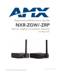
NXR-ZGW-PRO
NetLinx ZigBee Pro Gateway
NXR-ZRP-PRO
NetLinx ZigBee Pro Repeater
Control System Accessories
Last updated: 2/14/2012
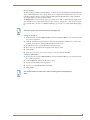
AMX Limited Warranty and Disclaimer
AMX warrants its products to be free of defects in material and workmanship under normal use for three (3) years from
the date of purchase from AMX, with the following exceptions:
•
Electroluminescent and LCD Control Panels are warranted for three (3) years, except for the display and touch
overlay components that are warranted for a period of one (1) year.
•
Disk drive mechanisms, pan/tilt heads, power supplies, and MX Series products are warranted for a period of one
(1) year.
•
AMX Lighting products are guaranteed to switch on and off any load that is properly connected to our lighting
products, as long as the AMX Lighting products are under warranty. AMX does guarantee the control of dimmable
loads that are properly connected to our lighting products. The dimming performance or quality cannot be
guaranteed due to the random combinations of dimmers, lamps and ballasts or transformers.
•
Unless otherwise specified, OEM and custom products are warranted for a period of one (1) year.
•
AMX Software is warranted for a period of ninety (90) days.
•
Batteries and incandescent lamps are not covered under the warranty.
This warranty extends only to products purchased directly from AMX or an Authorized AMX Dealer.
All products returned to AMX require a Return Material Authorization (RMA) number. The RMA number is obtained
from the AMX RMA Department. The RMA number must be clearly marked on the outside of each box. The RMA is
valid for a 30-day period. After the 30-day period the RMA will be cancelled. Any shipments received not consistent
with the RMA, or after the RMA is cancelled, will be refused. AMX is not responsible for products returned without a
valid RMA number.
AMX is not liable for any damages caused by its products or for the failure of its products to perform. This includes any
lost profits, lost savings, incidental damages, or consequential damages. AMX is not liable for any claim made by a
third party or by an AMX Dealer for a third party.
This limitation of liability applies whether damages are sought, or a claim is made, under this warranty or as a tort claim
(including negligence and strict product liability), a contract claim, or any other claim. This limitation of liability cannot
be waived or amended by any person. This limitation of liability will be effective even if AMX or an authorized
representative of AMX has been advised of the possibility of any such damages. This limitation of liability, however, will
not apply to claims for personal injury.
Some states do not allow a limitation of how long an implied warranty last. Some states do not allow the limitation or
exclusion of incidental or consequential damages for consumer products. In such states, the limitation or exclusion of
the Limited Warranty may not apply. This Limited Warranty gives the owner specific legal rights. The owner may also
have other rights that vary from state to state. The owner is advised to consult applicable state laws for full
determination of rights.
EXCEPT AS EXPRESSLY SET FORTH IN THIS WARRANTY, AMX MAKES NO OTHER WARRANTIES,
EXPRESSED OR IMPLIED, INCLUDING ANY IMPLIED WARRANTIES OF MERCHANTABILITY OR FITNESS FOR
A PARTICULAR PURPOSE. AMX EXPRESSLY DISCLAIMS ALL WARRANTIES NOT STATED IN THIS LIMITED
WARRANTY. ANY IMPLIED WARRANTIES THAT MAY BE IMPOSED BY LAW ARE LIMITED TO THE TERMS OF
THIS LIMITED WARRANTY.
FCC Information (FCC Rules CFR 47, Part 15,
Subpart C)
This device complies with Part 15 of the FCC Rules and Industry Canada RSS 210, subject to the following two
conditions: (1) this device may not cause harmful interference, and (2) this device must accept any interference
received; including interference that may cause undesired operation.
Federal Communications Commission (FCC)
Statement
This equipment has been tested and found to comply with the limits for a Class B digital device, pursuant to Part 15 of
the FCC rules. These limits are designed to provide reasonable protection against harmful interference in a residential
installation. This equipment generates, uses and can radiate radio frequency energy, and, if not installed and used in
accordance with the instructions, may cause harmful interference to radio communications. However, there is no
guarantee that interference will not occur in a particular installation. If this equipment does cause harmful interference
to radio or television reception, which can be determined by turning the equipment off and on, the user is encouraged
to try to correct the interference by one or more of the following measures:
•
Reorient or relocate the receiving antenna.
•
Increase the separation between the equipment and receiver.
•
Connect the equipment into an outlet on a circuit different from that to which the receiver is connected.
•
Consult the dealer or an experienced radio/TV technician for help.
Modifications not expressly approved by the manufacturer will void the user's authority to operate the equipment.
FCC RF Radiation Exposure Statement
WARNING: This device has been evaluated and found to be compliant with the FCC Rules for RF Exposure when the
device is operated at a minimum separation distance of 2 cm. from the user and nearby persons. Operation of this
device at closer distances should be avoided.
Software License and Warranty Agreement
LICENSE GRANT.
AMX grants to Licensee the non-exclusive right to use the AMX Software in the manner described in this License. The AMX Software is
licensed, not sold. This license does not grant Licensee the right to create derivative works of the AMX Software. The AMX Software consists
of generally available programming and development software, product documentation, sample applications, tools and utilities, and
miscellaneous technical information. Please refer to the README.TXT file on the compact disc or download for further information regarding
the components of the AMX Software. The AMX Software is subject to restrictions on distribution described in this License Agreement.
LICENSEE MAY NOT SUBLICENSE, RENT, OR LEASE THE AMX SOFTWARE. Licensee may not reverse engineer, decompile, or
disassemble the AMX Software.
INTELLECTUAL PROPERTY.
The AMX Software is owned by AMX and is protected by United States copyright laws, patent laws, international treaty provisions, and/or state
of Texas trade secret laws. Licensee may make copies of the AMX Software solely for backup or archival purposes. Licensee may not copy
the written materials accompanying the AMX Software.
TERMINATION.
AMX RESERVES THE RIGHT, IN ITS SOLE DISCRETION, TO TERMINATE THIS LICENSE FOR ANY REASON AND UPON WRITTEN
NOTICE TO LICENSEE. In the event that AMX terminates this License, the Licensee shall return or destroy all originals and copies of the
AMX Software to AMX and certify in writing that all originals and copies have been returned or destroyed.
PRE-RELEASE CODE.
Portions of the AMX Software may, from time to time, as identified in the AMX Software, include PRE-RELEASE CODE and such
code may not be at the level of performance, compatibility and functionality of the final code. The PRE-RELEASE CODE may not
operate correctly and may be substantially modified prior to final release or certain features may not be generally released. AMX is
not obligated to make or support any PRE-RELEASE CODE. ALL PRE-RELEASE CODE IS PROVIDED "AS IS" WITH NO
WARRANTIES.
LIMITED WARRANTY.
AMX warrants that the AMX Software will perform substantially in accordance with the accompanying written materials for a period of ninety
(90) days from the date of receipt. AMX DISCLAIMS ALL OTHER WARRANTIES, EITHER EXPRESS OR IMPLIED, INCLUDING, BUT NOT
LIMITED TO IMPLIED WARRANTIES OF MERCHANTABILITY AND FITNESS FOR A PARTICULAR PURPOSE, WITH REGARD TO THE
AMX SOFTWARE. THIS LIMITED WARRANTY GIVES LICENSEE SPECIFIC LEGAL RIGHTS. Any supplements or updates to the AMX
SOFTWARE, including without limitation, any (if any) service packs or hot fixes provided to Licensee after the expiration of the ninety (90) day
Limited Warranty period are not covered by any warranty or condition, express, implied or statutory.
LICENSEE REMEDIES.
AMX's entire liability and Licensee's exclusive remedy shall be repair or replacement of the AMX Software that does not meet AMX's Limited
Warranty and which is returned to AMX. This Limited Warranty is void if failure of the AMX Software has resulted from accident, abuse, or
misapplication. Any replacement AMX Software will be warranted for the remainder of the original warranty period or thirty (30) days,
whichever is longer. Outside the United States, these remedies may not available.
NO LIABILITY FOR CONSEQUENTIAL DAMAGES. IN NO EVENT SHALL AMX BE LIABLE FOR ANY DAMAGES WHATSOEVER
(INCLUDING, WITHOUT LIMITATION, DAMAGES FOR LOSS OF BUSINESS PROFITS, BUSINESS INTERRUPTION, LOSS OF BUSINESS INFORMATION, OR ANY OTHER PECUNIARY LOSS) ARISING OUT OF THE USE OF OR INABILITY TO USE THIS AMX SOFTWARE, EVEN IF AMX HAS BEEN ADVISED OF THE POSSIBILITY OF SUCH DAMAGES. BECAUSE SOME STATES/COUNTRIES DO
NOT ALLOW THE EXCLUSION OR LIMITATION OF LIABILITY FOR CONSEQUENTIAL OR INCIDENTAL DAMAGES, THE ABOVE LIMITATION MAY NOT APPLY TO LICENSEE.
U.S. GOVERNMENT RESTRICTED RIGHTS.
The AMX Software is provided with RESTRICTED RIGHTS. Use, duplication, or disclosure by the Government is subject to
restrictions as set forth in subparagraph ©(1)(ii) of The Rights in Technical Data and Computer Software clause at DFARS 252.2277013 or subparagraphs ©(1) and (2) of the Commercial Computer Software Restricted Rights at 48 CFR 52.227-19, as applicable.
SOFTWARE AND OTHER MATERIALS FROM AMX.COM MAY BE SUBJECT TO EXPORT CONTROL.
The United States Export Control laws prohibit the export of certain technical data and software to certain territories. No software from this Site
may be downloaded or exported (i) into (or to a national or resident of) Cuba, Iraq, Libya, North Korea, Iran, Syria, or any other country to
which the United States has embargoed goods; or (ii) anyone on the United States Treasury Department's list of Specially Designated Nationals or the U.S. Commerce Department's Table of Deny Orders. AMX does not authorize the downloading or exporting of any software or
technical data from this site to any jurisdiction prohibited by the United States Export Laws.
This Agreement replaces and supersedes all previous AMX Software License Agreements and is governed by the laws of the State of Texas,
and all disputes will be resolved in the courts in Collin County, Texas, USA. For any questions concerning this Agreement, or to contact AMX
for any reason, please write: AMX, 3000 Research Drive, Richardson, TX 75082.
Table of Contents
Table of Contents
Overview ............................................................................................................1
NXR-ZGW-PRO NetLinx ZigBee Pro Gateway ........................................................ 1
NXR-ZRP-PRO NetLinx ZigBee Pro Repeater .......................................................... 3
How ZigBee works.................................................................................................... 4
Network Structure .......................................................................................................... 4
Security ........................................................................................................................... 5
Personal Area Network - Limitations............................................................................... 5
Mesh Network Arrangements................................................................................... 5
Single Gateway Installations ........................................................................................... 5
Multiple Gateway Installations ........................................................................................ 6
Patents...................................................................................................................... 7
FCC Warning Statement ........................................................................................... 7
Installation ..........................................................................................................9
Overview .................................................................................................................. 9
Location and Antenna Direction...................................................................................... 9
Connecting the Optional Accessory Antennas.......................................................... 9
Connecting Power to the NXR-ZGW-PRO and NXR-ZRP-PRO ................................ 10
Determining the Power Source ..................................................................................... 10
Preparing Captive Wires for the 2-pin 3.5mm Captive Wire PWR Connector ............... 10
Using the PSN NetLinx connector for power ................................................................ 10
Connecting the NXR-ZGW-PRO to a LAN ............................................................... 11
Table-Top Installation ............................................................................................. 11
Rack-Mount Installation .......................................................................................... 11
Setting up a network ........................................................................................13
Overview ................................................................................................................ 13
Entering Devices Onto a Network .......................................................................... 14
NXR-ZGW-PRO Configuration Pages ................................................................17
Overview ................................................................................................................ 17
Configuration Manager........................................................................................... 17
Summary of Gateway Settings................................................................................ 18
Checking the Firmware Version.................................................................................................
Checking the ZigBee Firmware Version ....................................................................................
Determining the IP Settings of the NXR-ZGW-PRO ..................................................................
Finding the ICSP Device Number of the NXR-ZGW-PRO ..........................................................
Determining the PAN Settings of the NXR-ZGW-PRO ..............................................................
Determining the ZigBee Stack Profile .......................................................................................
Rebooting the NXR-ZGW-PRO ..................................................................................................
NXR-ZGW-PRO NetLinx ZigBee Pro Gateway & NXR-ZRP-PRO NetLinx ZigBee Pro Repeater
19
19
19
19
19
19
19
i
Table of Contents
Configuration.......................................................................................................... 19
Configuration - Network IP Settings tab ....................................................................... 20
Bonjour Settings ....................................................................................................................... 21
Setting the IP Address .............................................................................................................. 21
Setting the DNS Address.......................................................................................................... 21
Configuration - NetLinx Settings tab............................................................................. 22
Editing NetLinx Settings ........................................................................................................... 22
Setting Security Options........................................................................................................... 23
Configuration - User Settings tab.................................................................................. 23
Setting a New Username and Password ................................................................................... 23
Personal Area Network (PAN)................................................................................. 24
Personal Area Network (PAN) - Network tab ................................................................ 24
Enabling and Disabling the Wireless Network ..........................................................................
Enabling and Disabling the Use of a User-Defined Preshared Key ...........................................
Connecting an NXR-ZRP-PRO To the Network for the First Time.............................................
Setting the PAN Channel ..........................................................................................................
25
25
25
26
Personal Area Network (PAN) - Connections tab .......................................................... 26
Finding a Device’s EUI Address ................................................................................................
Finding the Device’s Description ..............................................................................................
Determining the Device Type ...................................................................................................
Determining a Device’s Current Power Source .........................................................................
Determining the Device’s Current Power Level ........................................................................
Checking the Device Link Status ...............................................................................................
27
27
27
27
27
27
Personal Area Network (PAN) - Commission Devices tab.............................................. 27
Commissioning Devices to a PAN ............................................................................................. 28
Personal Area Network (PAN) - PAN Device Details Page ............................................ 29
Changing the Extended PAN ID ............................................................................................... 30
Changing the AES Key .............................................................................................................. 30
Utilities.................................................................................................................... 31
Utilities - Device Firmware tab ...................................................................................... 31
Allowing Firmware Updates To Individual Devices ................................................................... 31
Allowing Firmware Updates To All Devices On a Network ....................................................... 32
Utilities - Connection Log tab........................................................................................ 32
Determining the Connection Status of a Device ....................................................................... 33
Finding a Device’s EUI Address ................................................................................................ 33
Finding the Device’s ICSP Number ........................................................................................... 33
Utilities - Traffic Log tab ................................................................................................ 33
Finding the Device’s ICSP Number ...........................................................................................
Finding a Device’s EUI Address ................................................................................................
Finding the Device’s Description ..............................................................................................
Determining the Device Type ...................................................................................................
Finding the Device Traffic .........................................................................................................
34
34
34
34
34
Programming the NXR-ZGW-PRO ....................................................................35
Overview ................................................................................................................ 35
SEND_COMMANDs ................................................................................................ 35
ii
NXR-ZGW-PRO NetLinx ZigBee Pro Gateway & NXR-ZRP-PRO NetLinx ZigBee Pro Repeater
Table of Contents
BUFF DEVICE SIZE ..................................................................................................................35
?VDEVS ...................................................................................................................................35
?VDEVINFO EUI ......................................................................................................................35
Device Configuration ........................................................................................37
Changing the NXR-ZGW-PRO’s Device Number..................................................... 37
Sending Firmware to The NXR-ZGW-PRO .............................................................. 37
Before Upgrading Firmware.......................................................................................... 37
Cautionary Notes .......................................................................................................... 37
Preparing the Master for Communication via IP............................................................ 37
Verifying and Upgrading Device Firmware via IP .......................................................... 37
NXR-ZGW-PRO NetLinx ZigBee Pro Gateway & NXR-ZRP-PRO NetLinx ZigBee Pro Repeater
iii
Table of Contents
iv
NXR-ZGW-PRO NetLinx ZigBee Pro Gateway & NXR-ZRP-PRO NetLinx ZigBee Pro Repeater
Overview
Overview
The NXR-ZGW-PRO NetLinx ZigBee Pro Gateway (FG5791-11) is an Ethernet to ZigBee wireless gateway,
designed as the center of a ZigBee Pro network. The NXR-ZGW-PRO features a 10/100BaseT, autonegotiating Ethernet port capable of Power over Ethernet (PoE), 16 Mbytes of Flash, 16 Mbytes of SDRAM,
and a ZigBee Pro transceiver, and is controlled via a web server interface.
The NXR-ZRP-PRO NetLinx ZigBee Pro Repeater (FG5791-03) is a ZigBee wireless repeater that features
one megabit of external memory and a ZigBee Pro transceiver. Both use the 2007 ZigBee Pro standards.
The NetLinx ZigBee Pro Gateway and Repeater are already enabled for ZigBee Pro
wireless communication. Neither device can be used with a standard ZigBee 2004 or
2006 wireless network; either the other devices in the network will need to be
updated to ZigBee Pro or the NXR-ZGW NetLinx Gateway (FG5791-01) and
NXR-ZRP Repeater (FG5971-02) should be used instead.
NXR-ZGW-PRO NetLinx ZigBee Pro Gateway
Antenna
Antenna
LEDs
ID Button
10/100BaseT modular
(RJ-45) Connector
2-pin 3.5mm
PWR connector
Front
Rear
Antenna Mount
FIG. 1 NXR-ZGW-PRO, front and rear
NXR-ZGW-PRO Specifications
Dimensions (HWD):
• 4.50" x 2.50" x 0.94" (114.30 mm x 63.50 mm x 23.81 mm)
• Depth does not include antenna
Weight:
• 0.35 lbs (158.76 g) without antenna
Power:
10.5 - 18 VDC; 13.5 (nominal operation voltage), or PoE Class 2
Memory:
• 16 Mbytes of Flash memory
• 0.40 lbs (181.44 g) with antenna
• 16 Mbytes of SDRAM
• 128K of microcontroller Flash memory
NXR-ZGW-PRO NetLinx ZigBee Pro Gateway & NXR-ZRP-PRO NetLinx ZigBee Pro Repeater
1
Overview
NXR-ZGW-PRO Specifications (Cont.)
Radio Specifications:
• Frequency: IEEE 802.15.4
• Operating channels: 1 - 26
• Modulation technique: DSS
• Output power: Region/country specific
• Coverage area (N America): 165 feet (50.2m)
IP Configuration:
Static IP or DHCP client
• DHCP default: DHCP/ZeroConf
• Static IP default: 169.254.1.2
Communications:
The NXR-ZGW-PRO communicates with a NetLinx master over TCP/IP
encapsulating the ICSP protocol via a physical Ethernet connection.
The ICSP device number can be set via the browser-based configuration
pages (page 17).
Front Components:
LEDs
• PWR/STATUS - A green LED that blinks every 5 seconds to indicate the
device is installed and communicating properly with the Master. Power ON,
but no Master connection, is indicated with a solid light; Power OFF is
indicated with no light.
• LAN - A green LED indicates an Ethernet connection is established. The LED
blinks to indicate both sending and receiving information via Ethernet.
• RF - The LED is solid when devices are connected; devices not connected is
indicated with no LED light; the LED blinks to indicate activity.
Antenna Mount
A reverse SMA connection that supports a 2.4GHz antenna.
ID Button
When used in conjunction with NetLinx Studio, sets the device and system
numbers for the NXR-ZGW-PRO.
Press and hold for approximately 30 seconds to return the NXR-ZGW-PRO to
factory default settings.
Rear Components:
Power connector
Two power options are available:
• 2-pin 3.5mm captive-wire PWR connector
• Power Over Ethernet (PoE) - powers the device through the CAT5 cable.
Both Power and Data can be transmitted simultaneously through the CAT5
cable when using the appropriate equipment.
10/100BaseT modular (RJ-45) connector - used to connect the
NXR-ZGW-PRO to your LAN and/or to connect your third party device to the
LAN when the NXR-ZGW-PRO is used as a gateway.
Ethernet port
Certifications:
• FCC ID: CWU-NXRZGWPRO
• IC: 5078B-ZGWPRO
• CE
• IEC-60950-1
• Japan Approval
• ZigBee Certified
Operating/Storage
Environments:
• Operating Temperature: -30°C (-22°F) to 70°C (158°F)
• Relative Humidity: 5% to 85% non-condensing
• Intended for indoor use only
Included Accessories:
• NXR-ZGW Installation Guide (93-5791-11)
• 2.4GHZ, MONO, RSMA, 3.5IN, 2.0DBI Antenna (70-0012-SA)
• Rubber feet
• Velcro mounting strip
• Power Supply (24-5791-SA)
Other AMX Products:
• Mio Modero R-3 Remote (FG148-03)
• Mio Modero R-4 Remote (FG148-04)
• NXR-ZRP-PRO NetLinx ZigBee Repeater (FG5791-03)
2
NXR-ZGW-PRO NetLinx ZigBee Pro Gateway & NXR-ZRP-PRO NetLinx ZigBee Pro Repeater
Overview
NXR-ZRP-PRO NetLinx ZigBee Pro Repeater
Antenna
Antenna
LEDs
2-pin 3.5mm
PWR connector
RESET Button
Front
Rear
Antenna Mount
FIG. 2 NXR-ZRP-PRO, front and rear
NXR-ZRP-PRO Specifications
Dimensions (HWD):
• 906 x 2.500 x 3.424 (23.01 mm x 63.50 mm x 86.96 mm)
• Depth does not include antenna
Weight:
• 0.25 lbs (113.39g)
Power:
10.5 - 18 VDC; 13.5 (nominal operation voltage)
Memory:
• 1 Megabit external memory
Radio Specifications:
• Frequency: IEEE 802.15.4
• 128K microprocessor Flash memory
• Operating channels: 11 - 26
• Modulation technique: DSS
• Output power: Region/country specific
• Coverage area (N America): 165 feet (50.2m)
Communications
The NXR-ZRP-PRO communicates with a Netlinx master via a NXR-ZGWPRO. The NXR-ZGW-PRO communicates with a Netlinx master over TCP/IP
encapsulating the ICSP protocol via a physical Ethernet connection. The ICSP
device number can be set via the browser-based management interface.
Front Components:
LEDs
• PWR/STATUS - A green LED that blinks to indicate the device is powered but
not commissioned to a network. A solid light indicates a device powered up
and commissioned; Power OFF is indicated with no light.
• ICSP - The LED is on when the device is connected to the gateway and off
when not connected.
• RF - The LED blinks when RF is active and is off when RF is inactive.
Antenna Mount
A reverse SMA connection that supports a 2.4GHz antenna.
Reset Button
Press and hold for approximately 10 seconds to return the NXR-ZRP-PRO to
factory default settings.
NXR-ZGW-PRO NetLinx ZigBee Pro Gateway & NXR-ZRP-PRO NetLinx ZigBee Pro Repeater
3
Overview
NXR-ZRP-PRO Specifications (Cont.)
Rear Components:
Power connector
Certifications:
• 2-pin 3.5mm captive-wire PWR connector
• FCC ID: CWU-ZRPPRO
• IC: 5078B-ZRPPRO
• CE
• IEC/EN-60950
• ZigBee Certified Product
Operating/Storage
Environments:
Included Accessories:
• Operating Temperature: -30°C (-22°F) to 70°C (158°F)
• Relative Humidity: 5% to 85% non-condensing; intended for indoor use only
• NXR-ZRP Installation Guide (93-5791-04)
• 2.4GHZ, MONO, RSMA, 3.5IN, 2.0DBI Antenna (70-0012-SA)
• Rubber feet
• Velcro mounting strip
• Power Supply (24-5791-SA)
Other AMX Products:
• Mio Modero R-3 Remote (FG148-03)
• Mio Modern R-4 Remote (FG148-04)
• NXR-ZGW-PRO NetLinx ZigBee Pro Gateway (FG5791-11)
• NXA-WAP 2413A Mounting Bracket (FG2255-24)
Connection to the Repeater device from either the NXR-ZGW-PRO or the Mio
Modero® R-3 or R-4 requires download and installation to the repeater of the latest
ZigBee Module firmware, available from www.amx.com.
How ZigBee works
The ZigBee wireless personal network technology protocol provides a framework for reliable, cost-effective,
low-power, wireless networked, monitoring and control products based on an open global standard. (More
information on the ZigBee standard is available at http://www.zigbee.org.) Many ZigBee-enabled devices use
ZigBee exclusively as a communication and control interface, but not all: some have the option of switching
between ZigBee, standard IR, or a combination of the two.
The NXR-ZGW-PRO, acting as a gateway, allows ZigBee-enabled devices to communicate both to and from
an ICSP master. A device connects to the NXR-ZGW-PRO and is then represented to the master as an ICSP
device. The master then communicates to the device through ICSP messages via a translation step at the NXRZGW-PRO level.
Network Structure
A ZigBee network is a Personal Area Network (PAN) consisting of one gateway, the option of one or more
repeaters, and one or more devices.
A gateway initiates a ZigBee network and all devices linking to the PAN gateway do so through either direct
links or through repeaters. The gateway’s job is to establish the network’s parameters, e.g., channel and
Extended PAN ID. Within each PAN, a gateway or repeater can each have up to 8 associated devices,
depending on the design of your system. Additional repeaters may be added to extend the range and reliability
of your PAN. Care should be taken to understand the associated increases in bandwidth consumption and
message latency.
A repeater like the NXR-ZRP-PRO is used to expand the coverage of NXR-ZGW-PRO gateways. Every
device in the PAN has a parent (a device connecting it to the coordinator or gateway), and repeaters can have
children (devices using them as a conduit to the master). Adding repeater devices to a network can reduce the
number of hops a device needs to make to reach the gateway. Repeaters have the additional advantage of
providing extra routing paths through the network, increasing reliability of the network. ZigBee Pro uses a
mesh structure, to provide a self-healing capacity. Repeaters are useful because they make that self-healing
possible. Adding repeaters also extends the coverage area for the entire network. Any device attached to a
repeater NXR-ZRP-PRO appears attached to the gateway NXR-ZGW-PRO in the Browser-Based
Configuration Manager pages.
4
NXR-ZGW-PRO NetLinx ZigBee Pro Gateway & NXR-ZRP-PRO NetLinx ZigBee Pro Repeater
Overview
A device will always connect to a repeater or gateway based on the least depth of the connection, and then the
best quality. For instance, given a choice between connecting to a repeater with two hops to a gateway or
directly to a gateway, a device will always connect first to the gateway, even if the repeater has a slightly better
connection. Devices cannot have children. The use of the NXR-ZGW-PRO and NXR-ZRP-PRO allow
ZigBee-type devices to roam seamlessly from repeater to repeater within the same Extended PAN ID.
Because of power saver options and other features, mobile devices tend to go into Standby mode frequently
and thus enter and leave the network regularly. While sleeping, the device may be in a new physical location or
the network may have changed channels. The device will seamlessly search for a new parent while sleeping
and scan channels upon awakening.
For more information on ZigBee network communication with other AMX products,
refer to the "Getting the Most From Your Mio Modero R-4" chapter in the Mio Modero
R-4 remote user manual or the ZigBee Tips Installation Guide, available at
www.amx.com.
Security
The NXR-ZGW-PRO device provides two levels of security using AES. Besides offering encryption with all
communication, AES encryption is always on. In addition, the gateway allows the use of 16-digit pre-shared
user-defined keys between devices in a Personal Area Network. For more information, please refer to the
Setting Security Options on page 23.
The NXR-ZGW-PRO ICSP security protocols allow one to use ICSP for authentication and encryption of
Ethernet communication with the Master.
Personal Area Network - Limitations
Within each Personal Area Network (PAN), a particular gateway can have up to 8 remote devices directly
accessing it. Each PAN may have limitations to the number of devices connected to a gateway, depending upon
local conditions. For more information, please refer to the How ZigBee works on page 4.
The IP configuration for the NXR-ZGW-PRO defaults to DHCP, but may be set to
Static in the Browser-Based Configuration Manager Pages (for more information,
please refer to the NXR-ZGW-PRO Configuration Pages on page 17). The default IP
address is 169.254.1.2, but if that address is in use by another device on the network,
the gateway will jump to a random address.
Mesh Network Arrangements
The following installations depend upon the criteria for the network. A small installation would perhaps only
need one NXR-ZGW-PRO to handle the devices in its network, while a larger installation might require a
NXR-ZGW-PRO and several NXR-ZRP-PROs to offer sufficient coverage.
When adding a ZigBee network to a NetLinx master, an Ethernet switch or hub must
be added to the master for proper function of the ZigBee network.
Single Gateway Installations
After you have installed the NXR-ZGW-PRO, you should consider the arrangement of devices. The following
is an example where only one NXR-ZGW-PRO is in the installation. This means that the installer has only one
Extended PAN ID with which to contend.
NXR-ZGW-PRO NetLinx ZigBee Pro Gateway & NXR-ZRP-PRO NetLinx ZigBee Pro Repeater
5
Overview
1 hop
NXR-ZGW-PRO
(Coordinator)
NetLinx Master
CAT5 Ethernet
connection
Mio R-4
FIG. 3 Single Extended PAN ID Network
See Setting up a network section on page 13 for setting the Extended PAN ID and adding device EUI-64
Addresses.
Multiple Gateway Installations
A more commercial application of the NXR-ZGW-PRO is having multiple gateways and specific devices
operating in close proximity of each other. Devices and repeaters of different networks can operate side-byside without interference. In the case of multiple networks in an area, it is best to use different channels for
each PAN, or to select a channel of "Any". "Any" will let a gateway spot other PANs in the area and choose the
best available channel for operation.
1 hop
NXR-ZGW
(Coordinator)
NetLinx Master
Extended PAN ID 1
CAT5
1 hop
2 hops
3 hops
NXR-ZGW-PRO
(Coordinator)
NXR-ZRP-PRO
(Router)
NXR-ZRP-PRO
(Router)
NetLinx Master
CAT5
Extended PAN ID 2
FIG. 4 Multiple Extended PAN ID Network
See Setting up a Network section on page 23 for setting the Extended PAN ID and adding device EUI
Addresses.
6
NXR-ZGW-PRO NetLinx ZigBee Pro Gateway & NXR-ZRP-PRO NetLinx ZigBee Pro Repeater
Overview
Patents
This product employs or practices certain features and/or methods of one or more of the following patents:
SIPCO, LLC
U.S. Patent No. 7,103,511
U.S. Patent No. 6,914,893
U.S. Patent No. 7,697,492
FCC Warning Statement
1. This equipment complies with Part 15 of the FCC rules. Any changes or modifications not expressly
approved by the manufacturer could void the user's authority to operate the equipment.
2. This device complies with Part 15 of the FCC rules subject to the following two conditions:
a. This device may not cause harmful interference.
b. This device must accept all interference received, including interference that may cause undesired
operation.
NXR-ZGW-PRO NetLinx ZigBee Pro Gateway & NXR-ZRP-PRO NetLinx ZigBee Pro Repeater
7
Overview
8
NXR-ZGW-PRO NetLinx ZigBee Pro Gateway & NXR-ZRP-PRO NetLinx ZigBee Pro Repeater
Installation
Installation
Overview
Several factors will help decide the best place to install NXR-ZGW-PRO and NXR-ZRP-PRO ZigBee Pro
devices. Before installing, consider the following:
Location and Antenna Direction
The best location for NXR-ZGW-PRO and NXR-ZRP-PRO devices are usually in the center of
your wireless network, with line of sight to all of your mobile devices.
Try placing the antenna in a position that can best cover your wireless network. Normally, the
higher you place the antenna, the better the performance you receive.
Try to place the gateway and repeater devices a reasonable distance away from each other to
minimize antenna feedback.
For minimal interference, try to keep any installed NXR-ZGW-PRO at least 10 feet (3.048m) from
any WiFi access points.
FIG. 5 displays the coverage for various positioning of the antenna.
FIG. 5 Horizontal and Vertical Antenna Radiation
Vertical radiation may vary slightly based on the selected channel.
Connecting the Optional Accessory Antennas
Several accessory 2.4GHz antennas are available for use with NXR-ZGW-PRO and NXR-ZRP-PRO. Each of
these antennas is uniquely suited to meet a wide variety of installation requirements.
NXR-ZGW-PRO NetLinx ZigBee Pro Gateway & NXR-ZRP-PRO NetLinx ZigBee Pro Repeater
9
Installation
Connecting Power to the NXR-ZGW-PRO and NXR-ZRP-PRO
The NXR-ZGW-PRO receives power via either PoE or 2-pin 3.5 mm mini-captive wire connection, while the
NXR-ZRP-PRO only utilizes the 2-pin 3.5 mm mini-captive wire connection.
When connecting both Ethernet and mini-captive wire connections to the NXR-ZGWPRO, PoE is overridden by the captive wire connection. PoE is only engaged if
Ethernet is the only power source available to the device.
If PoE is used, the NXR-ZGW-PRO will draw power through the CAT5 Ethernet cable, thereby allowing it to
be installed in areas without extra wiring for power (see Determining the Power Source section on page 10).
Determining the Power Source
The ability to choose a power supply option increases the availability of deployment locations. In addition, the
NXR-ZGW-PRO facilitates installation into areas previously without power, as it is not necessary to run
electrical wires to the device.
Based upon location and the availability of electricity, select one of the two following methods for power:
2-pin 3.5mm captive-wire connector - Prepare the captive wire pair and insert it into the
connector. See Preparing Captive Wires for the 2-pin 3.5mm Captive Wire PWR Connector section
on page 10.
This is the only power option for the NXR-ZRP-PRO.
Power Over Ethernet (PoE) (NXD-ZGW-PRO only) - If no electrical outlet is available, you can
plug one end of the CAT5 Ethernet cable into the RJ-45 jack of the NXR-ZGW-PRO and plug the
other end of the CAT5 cable into PoE supply equipment (this unit must be 802.3af compliant).
The NXR-ZGW is rated as a PoE Class 2 device that consumes about 2.5W, about 50mA to 60mA
at 48V.
Preparing Captive Wires for the 2-pin 3.5mm Captive Wire PWR Connector
If the 2-pin 3.5 mm mini-captive wire is selected, the following steps are necessary:
You will need a wire stripper and flat-blade screwdriver to prepare and connect the captive wires.
1. Strip 0.25 inch (6.35 mm) of wire insulation off all wires.
2. Insert each wire into the appropriate opening on the connector according to the wiring diagrams and
connector types described in this section.
3. Turn the screws clockwise to secure the wires in the connector. Do not over-torque the screws; doing so
can bend the seating pins and damage the connector.
Using the PSN NetLinx connector for power
The PWR and GND cable from the 12 VDC power supply must be connected to the corresponding location on
the 2-pin 3.5 mm mini-captive wire connector (FIG. 6).
PWR +
12 VDC Power Supply
GND FIG. 6 12 VDC Power Connector Wiring Diagram
1. Insert the PWR and GND wires on the terminal end of a PSN 2-pin 3.5 mm mini-captive wire cable.
Match the wiring locations of the +/- on both the power supply and the terminal connector.
2. Tighten the clamp to secure the two wires. Do not over-torque the screws, as doing so may strip the
threads and damage the connector.
3. Verify the connection of the 2-pin 3.5 mm mini-captive wire to the power supply.
10
NXR-ZGW-PRO NetLinx ZigBee Pro Gateway & NXR-ZRP-PRO NetLinx ZigBee Pro Repeater
Installation
Connecting the NXR-ZGW-PRO to a LAN
Insert one end of the CAT5 Ethernet cable into the rear RJ-45 jack (see FIG. 1 on page 1) and connect the other
end of the same cable to a master.
See Mesh Network Arrangements section on page 5 for possible network configurations.
Table-Top Installation
Using the provided rubber pads, place one in each bottom corner of the device. These will prevent scratches on
the table surface from the device casing.
Rack-Mount Installation
Using the Velcro pad provided, remove the backing and adhere one side to the device.
Remove the backing of the other side of the Velcro and place it on your rack where you want the NXR-ZGWPRO/ZRP-PRO mounted.
Before continuing, consult the Setting up a network on page 13.
NXR-ZGW-PRO NetLinx ZigBee Pro Gateway & NXR-ZRP-PRO NetLinx ZigBee Pro Repeater
11
Installation
12
NXR-ZGW-PRO NetLinx ZigBee Pro Gateway & NXR-ZRP-PRO NetLinx ZigBee Pro Repeater
Setting up a network
Setting up a network
Overview
The NXR-ZGW-PRO and NXR-ZRP-PRO constitute the full Master-to-Device control solution via a ZigBee
Pro wireless personal area network (PAN) using a mesh topology A variety of individual devices that can be
controlled or be the source of input to the system are supported.
This diagram in FIG. 7 shows MIO-R3 and MIO-R4 remotes connecting to a network via a NXR-ZGW
gateway and multiple NXR-ZRP repeaters.
FIG. 7 NXR-ZGW-PRO and NXR-ZRP-PRO Deployment View
When using ZigBee Pro firmware for a new or existing ZigBee network, you should
ensure that the network’s Master is upgraded to firmware version 3.41.422 or later.
ZigBee networks utilize a mesh topology, in that devices may interconnect, known as roaming, with different
ZigBee transceivers in an effort to get the best possible signal. The transceivers are known as parents. A
ZigBee network may contain at most one parent device that acts as a Coordinator.
NXR-ZGW-PRO NetLinx ZigBee Pro Gateway & NXR-ZRP-PRO NetLinx ZigBee Pro Repeater
13
Setting up a network
With an AMX system, the AMX NXR-ZGW-PRO fills that role. Multiple routers may be contained in a
ZigBee network, and the routers must have a reliable power source to keep the network assembled. ZigBee
messages travel through the network, attempting to minimize the hops between source and destination.
Routers, including the Coordinator, share routing information and establish paths through the network, which
is illustrated by the solid lines in FIG. 7.
Devices may only have one parent, usually a single router. However, they may be within range of multiple
routers, and choose to roam to a new parent based on signal strength, packet error rate, or some other
measurable data. The possible connections between devices and the routers in range are illustrated by the
dashed and dotted lines in FIG. 7.
Only one of these paths between a device and a router will be active until the device chooses to roam and find
a new parent. The active path is illustrated by the dotted lines. The active path may not always be the path with
the fewest hops through the network.
For example, if a device is moved behind a wall with sufficient RF absorption, the device may roam to a parent
with a stronger signal.
Devices may be mobile and may go into Standby Mode. Due to the mobile nature, previously out-of-range
routers may come within range and be roamed to as the device moves through the RF space. Due to the nature
of a typical standby cycle, in order to save battery life, a device will control the rate of the data it receives
based on its standby cycle.
Entering Devices Onto a Network
After establishing the location of the gateway (page 9), connecting it (page 11), providing power (page 10),
and placing the device in either a rack (page 11) or wall installation (page 11), you can then begin configuring
the NXR-ZGW-PRO and adding an NXR-ZRP-PRO and other ZigBee-compatible devices to the network.
1. Confirm that the NXR-ZGW-PRO is receiving power by checking the PWR LED on the front panel.
2. Using a PC connected to your NetLinx system, either open a web browser equipped with Zeroconf or
NetLinx Studio.
The NXR-ZGW-PRO will show up in the Zeroconf list as AMX NXR-ZGW SN# XXXX (“XXXX”
being the 16-digit serial number of the NXR-ZGW-PRO).
Double click on the device and the NXR-ZGW Browser-Based Configuration Manager will be
brought up.
If Zeroconf is not available, open a telnet session with the master and use the command “show
system” to obtain the IP address of the NXR-ZGW-PRO.
If more than one master is on the subnet, the NXR-ZGW-PRO will connect to the first one it senses,
so having only one master is highly recommended.
3. Access the NXR-ZGW on-line Configuration pages - enter the IP address of the NXR-ZGW-PRO into
your web browser (the default IP configuration for the NXR-ZGW-PRO is DHCP/Zeroconf).
4. Select the NetLinx Settings tab, and configure the NXR-ZGW-PRO to communicate with the master. See
the Configuration - NetLinx Settings tab section on page 22 for details.
5. Go to the PAN/Network tab and enable the wireless network. See the Personal Area Network (PAN) Network tab section on page 24 for details.
6. Turn on and/or configure ZigBee-compatible devices one at a time, e.g., Mio R-3 or Mio R-4. This
ensures that they are fully booted up before attempting to join the network.
7. Go to the Pan/Commissioning tab and allow joining. This enables joining for one minute and may need to
be repeated periodically. See the Personal Area Network (PAN) - Commission Devices tab section on
page 27 for details.
8. Start a network scan and select the appropriate Extended PAN ID (Mio R-3 and R-4 only).
9. For devices that do not have displays, such as the NXR-ZRP-PRO, or ones that have an insufficient
display to allow selection of the Extended PAN ID to join a network, place each device one at a time
within range of the gateway, turn on one of the devices, and configure it using the gateway web pages
before turning on the next one. With repeaters that have been on for some time, shut them down and
reboot them. Use the gateway to lock the device to the desired Extended PAN ID.
14
NXR-ZGW-PRO NetLinx ZigBee Pro Gateway & NXR-ZRP-PRO NetLinx ZigBee Pro Repeater
Setting up a network
If a repeater has been previously configured to a PAN, it must be reset to factory
defaults before it can join a different PAN.
This method may also be used if you do not want to go to each ZigBee compatible device to set the
Extended PAN ID. However, once each device is set, the change must be made to the gateway itself. It
may be necessary to cycle power on each device for them to come online.
10. Due to the wireless nature of the ZigBee network, temporary interference (such as leaving a room
or large objects passing between a remote and its gateway device) may prevent a command from
reaching the NetLinx master.
If this happens while increasing volume, the master may receive the command to
increase the volume but not the command to stop increasing it.
With this in mind, programmers should consider setting safeguards for volume control, either
through established volume limits or timeouts with the NetLinx master or more interactive
adjustment from the remote (i.e., direct volume control), to prevent issues with lost
commands.
To optimize the user experience and prevent delays in commands being received
and processed, limiting the number of “hops” between a ZigBee-enabled device and
the NetLinx master to two or less is highly recommended. For more information, see
both the How ZigBee works section on page 4, the “Getting the Most From Your Mio
Modero R-4” chapter in the Mio Modero R-4 Remote Operation/Reference Manual,
and the ZigBee Tips Installation Guide, all available at www.amx.com.
NXR-ZGW-PRO NetLinx ZigBee Pro Gateway & NXR-ZRP-PRO NetLinx ZigBee Pro Repeater
15
Setting up a network
16
NXR-ZGW-PRO NetLinx ZigBee Pro Gateway & NXR-ZRP-PRO NetLinx ZigBee Pro Repeater
NXR-ZGW-PRO Configuration Pages
NXR-ZGW-PRO Configuration Pages
Overview
To access the NXR-ZGW on-board Configuration pages, enter the IP address of the NXR-ZGW-PRO into
your web browser; the default IP configuration for the NXR-ZGW-PRO is DHCP/Zeroconf. Zeroconf will
broadcast its Web services and allow connection.
This broadcast may be viewed with any Zeroconf-enabled browser, such as NetLinx Studio or via the Bonjour
plug-in for Internet Explorer and Safari. When prompted, enter your username and password in the spaces
provided.
Upon accessing the Configuration Manager, the user must enter a username and
password. The default entries are “Admin” and “1988”, and passwords are always
case sensitive. Changing the default password as soon as possible is highly
recommended.
Copyright (c) 2007 GoAhead Software, Inc. All Rights Reserved.
Configuration Manager
All pages in the Configuration Manager offer the same buttons at the top of the page (FIG. 8).
FIG. 8 NXR-ZGW-PRO Configuration Manager - Page Heading
Consequently, a user may refresh the currently viewed page or log out of the Configuration Manager at any
time, and may access main categories from any other page.
NXR-ZGW-PRO Configuration Manager - Heading Options
• Logout
Clicking this button logs the user out of the Configuration Manager page.
• Refresh
Clicking this button refreshes the page, updating any information changed since the page
was last loaded in the browser.
• Summary
Clicking this button opens the Summary of Gateway Settings page (page 18).
• Configuration Clicking this button gives access to the Network IP Settings (page 20), NetLinx Settings
(page 22), and User Settings (page 23) pages.
• Pan
Clicking this button gives access to the Personal Area Network (PAN) (page 24) and
Connections (page 26) pages.
• Utilities
Clicking this button gives access to the Device Firmware (page 31), Connection Log
(page 32), and Traffic Log (page 33) pages.
NXR-ZGW-PRO NetLinx ZigBee Pro Gateway & NXR-ZRP-PRO NetLinx ZigBee Pro Repeater
17
NXR-ZGW-PRO Configuration Pages
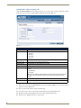
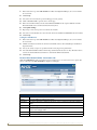
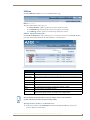
Summary of Gateway Settings
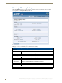
Click the Summary button to access the Summary of Gateway Settings page. This page is also the initial
access point for the Configuration Manager (FIG. 9).
FIG. 9 Summary of Gateway Settings Page
This page provides a quick summary of the current Gateway settings:
Summary of Gateway Settings Options
Version
Firmware
The version of the software running on the device.
ZigBee Firmware
The version of ZigBee software running on the device.
Serial Number
The serial number of the device as issued by AMX.
IP Settings
IP
The IP mode of the device (Static or Dynamic).
Host
The hostname of the device.
IP Address
The IP address of the device.
Subnet Mask
The subnet mask associated with IP addressing for the device.
Gateway
The IP gateway used by the device.
MacAddress
The MAC address of the device.
System Connection
Device ID
18
The ICSP device number of the device.
NXR-ZGW-PRO NetLinx ZigBee Pro Gateway & NXR-ZRP-PRO NetLinx ZigBee Pro Repeater
NXR-ZGW-PRO Configuration Pages
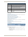
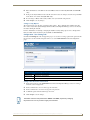
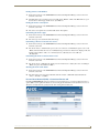
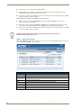
Summary of Gateway Settings Page (Cont.)
Pan Settings
Wireless
The state (Disabled/Enabled) of the wireless connection.
Channel
The ZigBee wireless channel used.
Extended Pan ID
The ZigBee personal area network ID used. Represented as "AZGXXXXX," where
"XXXXX" are the last five numbers of the device's serial number.
EUI
The Extended Unique Identifier. This is the ZigBee equivalent of a MAC address, as it
identifies the ZigBee hardware address for the gateway.
Preshared Key
The current use of a user-defined preshared key (Disabled/Enabled).
Access List
The current state of the Access List (Disabled/Enabled).
Pan ID
The number assigned to the device’s PAN network.
ZigBee Stack Profile The version of the ZigBee protocol running on the device.
• 1 = ZigBee 2004
• 2 = ZigBee 2007
Checking the Firmware Version
The firmware version is listed on the Summary of Gateway Settings page of the NXR-ZGW Browser-Based
Configuration Manager.
Checking the ZigBee Firmware Version
The ZigBee firmware version is listed on the Summary of Gateway Settings page, at the bottom of the page.
Determining the IP Settings of the NXR-ZGW-PRO
The IP settings are listed in the IP Settings section.
Finding the ICSP Device Number of the NXR-ZGW-PRO
The ICSP device number is listed under the System Connection, Device ID section.
Determining the PAN Settings of the NXR-ZGW-PRO
The PAN settings are listed in the PAN Settings section.
Determining the ZigBee Stack Profile
The Zigbee Stack Profile lists the version of the ZigBee protocol currently running on the NXR-ZGW-PRO.
This will always be "2".
Rebooting the NXR-ZGW-PRO
Click the Reboot button on the left bottom of the Summary of Gateway Settings page.
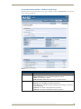
Configuration
Click the Configuration button (FIG. 10) to access the tabbed Configuration page.
FIG. 10 Configuration Button
The tabs contained in the Configuration page are:
IP Settings - Click to open the Network IP Settings tab (see the Configuration - Network IP
Settings tab section on page 20)
NetLinx Settings - Click to open the Network IP Settings tab (see the Configuration - NetLinx
Settings tab section on page 22)
User Settings - Click to open the Network IP Settings tab (see the Configuration - User Settings
tab section on page 23)
NXR-ZGW-PRO NetLinx ZigBee Pro Gateway & NXR-ZRP-PRO NetLinx ZigBee Pro Repeater
19
NXR-ZGW-PRO Configuration Pages
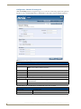
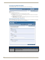
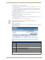
Configuration - Network IP Settings tab
Click the IP Settings tab of the Configuration page to access the Network IP Settings options. The options in
this tab are used to set IP and DNS addresses. The IP address can be either a static or dynamic assignment.
FIG. 11 Network IP Settings Page
Configuration - Network IP Settings tab options
IP Address
IP
• Dynamic: IP address and subnet mask are requested from the DHCP server.
• Static: User provides IP address information.
Host
The hostname of the device.
IP Address
The IP address of the device.
Subnet Mask
The IP subnet mask of the device.
Gateway
The gateway used for IP routing.
Bonjour Settings
Bonjour
The button allowing use of the Zeroconf plug-in for Internet Explorer or Safari
(Enabled/Disabled).
Name
The name of the Zeroconf shortcut.
The DNS Address allows the IP addresses of domain name servers to be specified.
DNS Address
20
Domain Suffix
The domain name.
Primary DNS - Secondary DNS
Domain Name System IP numbers associated to the domain suffix.
NXR-ZGW-PRO NetLinx ZigBee Pro Gateway & NXR-ZRP-PRO NetLinx ZigBee Pro Repeater
NXR-ZGW-PRO Configuration Pages
Bonjour Settings
The Bonjour plug-in for Microsoft Internet Explorer 7 allows selection of information for individual Gateway
devices within a Web browser. Zeroconf, also known as zero-configuration networking, allows users to locate
networked computers, printers, and other equipment without knowing their IP address settings and without
special serial cables or product-specific PC software.
The Bonjour button on the Network IP Settings page allows one to enable or disable the Bonjour plug-in. The
Name field allows one to enter a unique name for a Zeroconf device shortcut. Once a name has been selected
for a particular device, the device’s Configuration Manager pages may be accessed through the Bonjour plugin.
The Bonjour plug-in may be downloaded from www.apple.com.
Setting the IP Address
1. In the menu at the top of the NXR-ZGW Browser-Based Configuration Manager, select IP Settings under
the section Configuration.
2. Click the radio button for either Dynamic or Static. If your network has a DHCP server, you may select
Dynamic, and the gateway will request IP information from the server.
3. If configured for Static, type the IP address in the field provided.
4. If necessary, type the subnet mask and gateway in the fields provided.
5. Click Accept.
6. In the The system will need to reboot for changes to take effect window, click OK.
Setting the DNS Address
1. In the menu at the top of the NXR-ZGW Browser-Based Configuration Manager, select IP Settings under
the section Configuration.
2. Click the Static radio button in the IP Address section.
3. Type the Domain Suffix in the field provided.
4. Type the necessary DNS IP numbers in the fields.
5. Click Accept.
Any changes made to the network IP or Zeroconf settings will force the gateway to
reboot.
NXR-ZGW-PRO NetLinx ZigBee Pro Gateway & NXR-ZRP-PRO NetLinx ZigBee Pro Repeater
21
NXR-ZGW-PRO Configuration Pages
Configuration - NetLinx Settings tab
Click the NetLinx Settings tab of the Configuration page to access the NetLinx Settings options. The options
in this tab are used to view or edit the NetLinx settings for this gateway (FIG. 12):
FIG. 12 NetLinx Settings Page
Configuration - NetLinx Settings tab options
Connection
The mode in which the connection to the master is being made. Default: ID Mode.
Mode
The NetLinx mode being used. Selected from:
• TCP Auto
• TCP URL
• TCP Listen
• UDP URL
System Number
The number for the NetLinx network
Device Number
The network number assigned to the device
Master IP/URL:
The IP address or URL assigned to the master
Master Port Number
The port used by the master
Security
The current selected security setting for the network:
• None
• Authenticated
• Encrypted
Note: Security settings are determined by the master, and cannot be changed from
this page. For more information, refer to the security setup information for the
master.
Username
The user name registered with the master
Password
The password registered with the master.
Editing NetLinx Settings
1. In the menu at the top of the NXR-ZGW Browser-Based Configuration Manager, select NetLinx Settings
under the section Configuration.
2. The Connection field cannot be changed from this page.
3. Select between the choices in the Mode dropdown menu for the desired NetLinx mode.
4. Enter the network system number in the System Number field (Automode only).
5. Enter the device number in the Device Number field.
22
NXR-ZGW-PRO NetLinx ZigBee Pro Gateway & NXR-ZRP-PRO NetLinx ZigBee Pro Repeater
NXR-ZGW-PRO Configuration Pages
6. Enter the IP address or the URL for the network Master in the IP/URL field (TCP URL and UDP URL
only).
7. If the port used by the Master for its network connection needs to be changed, enter the new port number
in the Master Port Number field (TCP URL only).
8. If connecting to a Master with security enabled, enter your username and password.
9. Click Accept to save any changes.
Setting Security Options
The NetLinx Settings page has three potential security settings: None, Authenticated, and Encrypted. All
three of these may not be adjusted through the Browser-Based Configuration Manager, as these are all set by
the master running the network.
For more information on activating or changing the NetLinx security settings, please refer to the Operation
Reference Guide for the master being used (available at www.amx.com).
Configuration - User Settings tab
Click the User Settings tab of the Configuration page to access the User Settings options. The options in this
tab are used to set the username and password for access to the NXR-ZGW-PRO on-board Configuration
pages.
FIG. 13 Configuration - User Settings page
Configuration - User Settings tab options
New Username
Text field for new username.
New Password
Text field for new password.
Re-type Password Text field to confirm new password.
Setting a New Username and Password
1. In the menu on the top of the NXR-ZGW Browser-Based Configuration Manager, select User Settings
under the section Configuration.
2. In the text field next to New Username, type the new name.
3. In the text field next to New Password, type the new password.
4. Confirm the password in the field Re-type Password.
5. Click Accept to save the changes.
The default username and password are “Admin” and “1988”, respectively. Changing
the password as soon as possible is highly recommended.
NXR-ZGW-PRO NetLinx ZigBee Pro Gateway & NXR-ZRP-PRO NetLinx ZigBee Pro Repeater
23
NXR-ZGW-PRO Configuration Pages
Personal Area Network (PAN)
Click the Pan button (FIG. 14) to access the tabbed Personal Area Network (PAN) page.
FIG. 14 Pan Button
The tabs contained in the Pan page are:
Network - Click to open the Network IP Settings tab (see below)
Connections - Click to open the Network IP Settings tab (see the Personal Area Network (PAN) Connections tab section on page 26)
Commissioning- Click to open the Network IP Settings tab (see the Personal Area Network (PAN)
- Commission Devices tab section on page 27)
Personal Area Network (PAN) - Network tab
Click the Network tab of the Personal Area Network (PAN) page to access the Network tab. The options in this
tab are used to view/modify the PAN settings for this gateway (FIG. 15).
FIG. 15 Personal Area Network (PAN) - Network tab
Personal Area Network (PAN) Network tab options
Network status
Lists whether the network is online, offline, or in Standby.
Extended PAN ID The current Extended PAN ID number for the device. This is automatically provided by the
device, and cannot be changed
Wireless
24
Enables or disables the ZigBee wireless networking.
NXR-ZGW-PRO NetLinx ZigBee Pro Gateway & NXR-ZRP-PRO NetLinx ZigBee Pro Repeater
NXR-ZGW-PRO Configuration Pages
Personal Area Network (PAN) Network tab options (Cont.)
Encryption
The encryption status of the network. Encryption is always on in a ZigBee network.
Preshared Key
When this parameter is enabled, all devices in the network must be commissioned to have
the same preshared key to join the network.
AES Key
This is the user supplied preshared key value. It is a 32 digit hexadecimal key used for
communications between the gateway and a device when the device is joining.
Country/Region
Drop down menu; sets ZigBee region (US, Europe, Japan).
Channel
Drop down menu; sets the ZigBee operating channel between 11 and 26. The default channel is "Any". "Any" will look for the channel with the least interference.
The Extended PAN ID number is derived from the NXD-ZGW’s serial number, and
cannot be changed. If two devices in a network should somehow have the same
extended PAN number, then return the device to AMX.
If the PAN shows as "Offline" when the NXR-ZGW-PRO is in Standby Mode, update
the Master’s firmware.
Enabling and Disabling the Wireless Network
1. In the menu on the top of the NXR-ZGW Browser-Based Configuration Manager, select Network under
the section Pan.
2. Click the radio button next to Enabled to enable the wireless network or select Disabled to disable the
network.
3. Click Accept.
Enabling and Disabling the Use of a User-Defined Preshared Key
All devices in a PAN automatically have encryption of incoming and outgoing packets via a randomly
generated network key. Clicking Enabled on the Preshared Key entry allows use of a key applied to all devices
on the PAN.
The AES key is a 32-digit hexidecimal key with a colon (:) between each two digits. The numbers 0 through 9
and the letters A through F are valid for use in an AES key. This key may be generated by the user, or it can be
provided by the network. If you enable the Preshared Key entry but do not enter a key, the system will generate
a random key for you. Make sure to enter this AES key on every device within the PAN through the Pan/
Connections page (see the Personal Area Network (PAN) - Connections tab section on page 26).
If a user defined preshared key is desired and that key does not have 32 digits or if all digits are zero, the
system will recognize this as an invalid key and the user specified key will not be used.
If the network should become insecure, such as with a temporary power loss, then all unkeyed devices are lost
to the network. When a device is lost, the Browser-based Configuration Manager may need as much as 50
seconds to reflect this. Keyed devices will attempt to reconnect to the PAN, or to the nearest available PAN if
their chosen one is unavailable. Make sure to connect the gateway LAST.
Any change to network settings from the Browser-based Configuration Manager will
require formal joining of all network devices.
Connecting an NXR-ZRP-PRO To the Network for the First Time
When a NXR-ZRP is powered on for the first time, it will be set to factory defaults and will join the first AMX
ZigBee Network that it detects with Allow Joining turned on. Once joined, it will appear on the list on the
Commission Devices page (see the Personal Area Network (PAN) - Commission Devices tab section on
page 27).
Clicking on the EUI-64 number of the device on the Commission Devices page will open the PAN Device
Details page for that device (see the Personal Area Network (PAN) - PAN Device Details Page section on
page 29).
It is suggested that only one gateway should set to allow joining when commissioning a network.
NXR-ZGW-PRO NetLinx ZigBee Pro Gateway & NXR-ZRP-PRO NetLinx ZigBee Pro Repeater
25
NXR-ZGW-PRO Configuration Pages
1. In the menu on the top of the NXR-ZGW Browser-Based Configuration Manager, select Network under
the section Pan.
2. Click Accept.
3. Select the Connections tab; the repeater should appear on the gateway.
4. Click on the EUI-64 link to open the Device Details page.
5. In the Extended PAN ID field, enter the desired Extended PAN ID for the repeater within the network.
This field defaults to the current network to which it is joined.
6. Click Update Settings.
7. Repeat steps 1-6 for each repeater to be added to the network.
8. Select the Network tab under the section Pan and enter the desired Extended PAN ID in the PAN ID field.
9. Click Accept.
Setting the PAN Channel
1. In the menu on the top of the NXR-ZGW Browser-Based Configuration Manager, select Network under
the section Pan.
2. Click the radio button to Disable the wireless network. This activates the Country/Region and Channel
dropdown menus.
3. Select your country or region of operation from the Country/Region drop down menu.
4. Select the Channel number from the Channel drop down menu. The selection of "Any" allows the radio to
scan for the channel with the least interference and form the PAN on that channel.
5. Click Accept.
Personal Area Network (PAN) - Connections tab
Click the Connections tab of the Personal Area Network (PAN) page to access the Connections options. All
devices connected to the NXR-ZGW-PRO are displayed on this page.
FIG. 16 Personal Area Network (PAN) - Connections tab
Personal Area Network (PAN) - Connections tab options
No.
The Netlinx ID number.
EUI-64
The 64-bit ZigBee EUI address of the device.
Description
The device's description, supplied by the device. If none is entered, the description defaults to
"Blank".
Type
The specific type of device being accessed.
Power Source The source of power currently being used by the device. "Mains" means that the handheld
device is in its charging cradle.
26
Power Level
The current charge on the handheld device’s battery.
Status
The current status of the device: either "Active" or "Standby".
NXR-ZGW-PRO NetLinx ZigBee Pro Gateway & NXR-ZRP-PRO NetLinx ZigBee Pro Repeater
NXR-ZGW-PRO Configuration Pages
Finding a Device’s EUI Address
1. In the menu on the top of the NXR-ZGW Browser-Based Configuration Manager, select Connections
under the section Pan.
2. The EUI address is located in the Connections table under “EUI-64”. Click on the EUI address to open
the PAN Device Details page for this device. (See FIG. 18)
Finding the Device’s Description
1. In the menu on the top of the NXR-ZGW Browser-Based Configuration Manager, select Connections
under the section Pan.
2. The device’s description is located in the table under "Description".
Determining the Device Type
1. In the menu on the top of the NXR-ZGW Browser-Based Configuration Manager, select Connections
under the section Pan.
2. The device type is located in the table under "Type".
Determining a Device’s Current Power Source
1. In the menu on the top of the NXR-ZGW Browser-Based Configuration Manager, select Connections
under the section Pan.
2. The "Power Source" column lists the power sources of each device on the PAN. If a power source reads
"Mains", this means that the device is a normally battery-powered device that is in its charging cradle and
drawing power from the cradle, or is a non-battery device. Otherwise, the device will read
"Rechargeable".
Determining the Device’s Current Power Level
1. In the menu on the top of the NXR-ZGW Browser-Based Configuration Manager, select Connections
under the section Pan.
2. The "Power Level" column lists the current power level of the device’s battery. If a device is running in
"Mains", the power level will read "100%".
Checking the Device Link Status
1. In the menu on the top of the NXR-ZGW Browser-Based Configuration Manager, select Connections
under the section Pan.
2. The status of the device is located in the table under the "Status" column. This status will either be
"Active", "Standby", or "Offline".
Personal Area Network (PAN) - Commission Devices tab
Click the Commissioning tab of the Personal Area Network (PAN) page to access the Commission Devices
options (FIG. 17). The options in this tab are used to bring up the network in an orderly fashion. Devices are
allowed to join only when the gateway has the Allow Joining function turned on.
FIG. 17 Personal Area Network (PAN) - Commission Devices tab
NXR-ZGW-PRO NetLinx ZigBee Pro Gateway & NXR-ZRP-PRO NetLinx ZigBee Pro Repeater
27
NXR-ZGW-PRO Configuration Pages
Personal Area Network (PAN) - Commission Devices tab options
Auto Refresh:
The current ability to automatically refresh the page to display new devices during the
scanning period: either "On" or "Off".
Refresh List:
Manually refreshes the list of detected devices when pressed.
EIU-64:
The resource number of a particular detected device.
Device Type:
The type of device being commissioned. This information is provided by the device.
Description:
A detailed description of the device being commissioned. This information is
designated by the user.
Status:
The current connection status of the device.
Allow Joining:
This button, when pressed, allows devices to join the network.
Commissioning Devices to a PAN
1. In the menu on the top of the NXR-ZGW Browser-Based Configuration Manager, select Pan/
Commissioning.
2. If the device is not on the network and is set to factory defaults, make sure the device is powered and click
the Allow Joining button.
3. Wait for the device to show up in the Commissioning tab.
4. Click on the EUI-64 link to open the Device Details page (page 29).
5. In the Extended PAN ID field, enter the desired Extended PAN ID for the device within the network. This
field will default to the current network.
6. Click Update Settings.
7. Repeat steps 1-6 for each device to be added to the network.
When commissioning devices to a PAN, use only one gateway at a time. Allowing
joins on multiple gateways simultaneously can give unpredictable results.
If the existing ZigBee system contains a repeater and the user decides to form a new
PAN (through channel changing or an AES key update), the repeater must be
commissioned to the PAN first, before commissioning any devices.
If you try to commission any device before commissioning repeaters, you will see
duplicate entries for the same Extended PAN ID: one with "Join" status set to "no"
from the repeaters and another one with "Join" status set to "yes" from the gateway.
When a NXR-ZRP is powered on for the first time, it will be set to factory defaults and will join the first AMX
ZigBee Network that it detects with Allow Joining turned on. Once joined, it will appear on the list on the
Commission Devices page. Clicking on the EUI-64 number of the device on the Commission Devices page will
open the PAN Device Details page for that device.
If the device is to remain on the network to which it is currently joined and no user defined AES key
is required, click Update Settings to complete commissioning.
If the device is to join a different network or a user defined AES key is required, enter the Extended
Pan ID of the network to join in the Extended Pan ID block and/or the user defined AES key in the
AES Key block and click Update Settings to complete commissioning.
The PWR/STATUS LED (top LED) of the NXR-ZRP will remain on constantly when
commissioning is complete.
28
NXR-ZGW-PRO NetLinx ZigBee Pro Gateway & NXR-ZRP-PRO NetLinx ZigBee Pro Repeater
NXR-ZGW-PRO Configuration Pages
Personal Area Network (PAN) - PAN Device Details Page
From the Connections or the Commission Devices pages, clicking on a device’s EUI-64 number opens the Pan
Device Details page (FIG. 18).
FIG. 18 PAN Device Details Page
Personal Area Network (PAN) - Pan Device Details page options
Leave Network
Connected Device
This button removes a device from its PAN if clicked.
• Device Type: The type of network device.
• Device Description: The user-defined description of the device.
• Status: Active, Standby, or Offline
• ICSP Connection: Notes whether the device is connected via ICSP.
Device Networking
• EUI-64: The 64-bit ZigBee EUI address of the device.
• Node ID: The 16-bit ZigBee short address of the device.
• Link Quality: The combination of signal strength and packet integrity of the device’s
connection (0-255).
• Traffic RX: The number of data packets sent to the device.
• Traffic TX: The number of data packets received by the device.
NXR-ZGW-PRO NetLinx ZigBee Pro Gateway & NXR-ZRP-PRO NetLinx ZigBee Pro Repeater
29
NXR-ZGW-PRO Configuration Pages
PAN Device Details Page (Cont.)
Device Information
• Power Sources: All of the possible sources for power for the device, including
mains electric power and rechargeable battery backup
• Current Power: Current power source being used by the device.
• Power Level: Amount of required power currently being received by the device.
• Host F/W Version: Latest firmware version installed in the device.
• Serial Number: The serial number of the device.
• Node Type: The ZigBee node designation. Including log details of that device only.
ZigBee Networking
• Application Version: The version of the ZigBee application being used.
• Extended Pan ID: ID number for the device within the PAN.
• AES Key: The user-defined security key used by the ZigBee network.
Changing the Extended PAN ID
The Extended PAN ID for the device may be changed via the field on the PAN Device Details page. Changing
this information will require joining to be allowed on the new network.
If the Extended PAN ID for the device is changed, then any connection to an existing
PAN will be lost. Changing the PAN ID will require having to reconnect the device to
the PAN, or to another PAN in the same area.
Changing the AES Key
The 16-digit AES key for a particular device in a PAN may be changed from the AES Key field in the ZigBee
Networking section of the PAN Device Details page. For more information on changing the AES Key for a
PAN device, please refer to the Enabling and Disabling the Use of a User-Defined Preshared Key on page 25.
30
NXR-ZGW-PRO NetLinx ZigBee Pro Gateway & NXR-ZRP-PRO NetLinx ZigBee Pro Repeater
NXR-ZGW-PRO Configuration Pages
Utilities
Click the Utilities button (FIG. 19) to access the tabbed Utilities page.
FIG. 19 Utilities Button
The tabs contained in the Utilities page are:
Device Firmware - Click to open the Device Firmware tab (see below)
Connection Log - Click to open the Connection Log tab (see the xxxxxx)
Traffic Log- Click to open the Network IP Settings tab (see the xxxxxxx
Utilities - Device Firmware tab
Click the Device Firmware tab of the Utilities page to access the Device Firmware options (FIG. 20). This
page shows all the information about the status of firmware on network devices.
FIG. 20 Utilities - Device Firmware tab
Utilities - Device Firmware tab options
Auto Refresh
Automatically and regularly refreshes the Device Firmware Status list.
Refresh List
Manually refreshes the Device Firmware Status list.
Allow Updates
Selects all devices listed in the Device Firmware Status list and turns all permissions On or
Off.
Updates
Sets permissions to allow firmware uploads to the selected device.
EUI-64
The 64-bit EUI address of the device.
Description
The user-provided description of the device.
Status
The current activity of the device, whether active, standby, or offline.
Version
The current version of the ZigBee firmware.
Upload Status
Displays the ability of the firmware to be uploaded with new firmware. Handheld devices
will not receive uploads until they are placed in their charging cradles.
Devices showing an Upload Status of "Place In Charger" will not receive firmware
uploads until they are inserted into their charging cradles.
Allowing Firmware Updates To Individual Devices
1. In the menu on the top of the NXR-ZGW Browser-Based Configuration Manager, select Device
Firmware under the section Utilities.
NXR-ZGW-PRO NetLinx ZigBee Pro Gateway & NXR-ZRP-PRO NetLinx ZigBee Pro Repeater
31
NXR-ZGW-PRO Configuration Pages
2. Choose the device to be updated by its EUI-64 number.
3. Click the button next to the device’s EUI-64 number in the Allow Updates column. The page will
automatically refresh, displaying the device’s new status.
4. Some devices cannot have their firmware update status changed; these devices will continue to read Off
even after selecting to allow new updates.
Allowing Firmware Updates To All Devices On a Network
1. In the menu on the top of the NXR-ZGW Browser-Based Configuration Manager, select Device
Firmware under the section Utilities.
2. In the Allow Updates column, click All On or All Off to allow or block upgrades to all devices on the
network. The page will automatically refresh, displaying the new status of all network devices.
3. Some devices cannot have their firmware update status changed; these devices will continue to read Off
even after selecting to allow new updates.
Clicking on the EUI-64 number in the Device Firmware page will open the device’s
PAN Device Details page (see FIG. 18).
Utilities - Connection Log tab
Click the Connection Log tab of the Utilities page to access the Connection Log (FIG. 20). The Connection
Log is a list of all recent ZigBee device activity.
FIG. 21 Utilities - Connection Log tab
Utilities - Connection Log tab options
Auto Refresh
32
Automatically and regularly refreshes the Connection Log listings.
Refresh List
Manually refreshes the Connection Log listings.
Clear List
Manually clears all entries in the Connection Log listings.
#
The device’s log entry number
Time
The time the device last made or lost connection with the network.
Connection
Indicates the device and its latest connection status.
EUI-64
The 64-bit EUI address of the device.
Device #
The device's ICSP device number.
NXR-ZGW-PRO NetLinx ZigBee Pro Gateway & NXR-ZRP-PRO NetLinx ZigBee Pro Repeater
NXR-ZGW-PRO Configuration Pages
Determining the Connection Status of a Device
1. In the menu on the top of the NXR-ZGW Browser-Based Configuration Manager, select Connection Log
under the section Utilities.
2. The connection status of each device is located in the column Connection; the possible values are either
Connected or Disconnected. The time in which the device either connected to the network or lost its
connection is located under the column Time.
Finding a Device’s EUI Address
1. In the menu on the top of the NXR-ZGW Browser-Based Configuration Manager, select Connection Log
under the section Utilities.
2. The EUI address of each device is located in the column EUI-64.
Finding the Device’s ICSP Number
1. In the menu on the top of the NXR-ZGW Browser-Based Configuration Manager, select Connection Log
under the section Utilities.
2. The ICSP number of each device is located in the column Device #.
Clicking on the EUI-64 number in the Connection Log page will open the device’s
PAN Device Details page (see FIG. 18).
Utilities - Traffic Log tab
Click the Traffic Log tab of the Utilities page to access the Traffic Log (FIG. 22). The traffic log shows traffic
statistics for all ZigBee devices.
FIG. 22 Utilities - Traffic Log tab
Utilities - Traffic Log tab options
Auto Refresh
Automatically and regularly refreshes the Traffic Log listings.
Refresh List
Manually refreshes the Traffic Log listings.
Clear List
Manually clears all entries in the Traffic Log listings.
Device #
The device's ICSP device number.
EUI-64
The 64-bit EUI address of the device.
Description
The device's description, supplied by the device.
Device Type
The type of device tracked by the Traffic Log.
RX
The total number of bytes received by the device since it connected.
TX
The total number of bytes transferred to the device since it connected.
NXR-ZGW-PRO NetLinx ZigBee Pro Gateway & NXR-ZRP-PRO NetLinx ZigBee Pro Repeater
33
NXR-ZGW-PRO Configuration Pages
Utilities - Traffic Log tab options (Cont.)
Buffers
Current
The current number of buffers being used on the device.
Threshold
The maximum number of buffers available for use on the device. Exceeding this number will
cause the device to fall offline.
Max
The maximum number of buffers that have been used since the last time the traffic log was
cleared.
Finding the Device’s ICSP Number
1. In the menu on the top of the NXR-ZGW Browser-Based Configuration Manager, select Traffic Log
under the section Utilities.
2. The ICSP number of each device is located in the column Device #.
Finding a Device’s EUI Address
1. In the menu on the top of the NXR-ZGW Browser-Based Configuration Manager, select Traffic Log
under the section Utilities.
2. The EUI address of each device is located in the column EUI-64.
Finding the Device’s Description
1. In the menu on the top of the NXR-ZGW Browser-Based Configuration Manager, select Traffic Log
under the section Utilities.
2. The description of each device is located in the column Description.
Determining the Device Type
1. In the menu on the top of the NXR-ZGW Browser-Based Configuration Manager, select Traffic Log
under the section Utilities.
2. The type of each device is located in the column Device Type.
Finding the Device Traffic
1. In the menu on the top of the NXR-ZGW Browser-Based Configuration Manager, select Traffic Log
under the section Utilities.
2. The traffic byte count of each device is located within the columns RX and TX. RX lists received traffic,
while TX lists transmitted traffic.
Clicking on the EUI-64 number in the Traffic Log page will open the device’s PAN
Device Details page (FIG. 18).
34
NXR-ZGW-PRO NetLinx ZigBee Pro Gateway & NXR-ZRP-PRO NetLinx ZigBee Pro Repeater
Programming the NXR-ZGW-PRO
Programming the NXR-ZGW-PRO
Overview
Some of the functionality of the NXR-ZGW-PRO may be handled using the application TPDesign4. Go to
www.amx.com for the supporting documentation. The NXR-ZGW-PRO recognizes a select number of
NetLinx Commands.
SEND_COMMANDs
Below is a list of SEND_COMMANDs accepted by the NXR-ZGW-PRO from NetLinx masters. To use these
commands, establish a Telnet session from the PC to the NetLinx master. Additionally, you could use NetLinx
Studio or the master’s web page to send the commands.
Send Commands
BUFF DEVICE SIZE This command increases the buffer size for a specific DEVICE to SIZE.
This change is temporary, and the buffer size will revert to its original size after 30
seconds.
?VDEVS
Returns a list of all ZigBee devices that are currently on the gateway.
The devices will be returned to the master as send commands.
Syntax:
"^VDEVS-X,EUI"
• X = the index of the device
• EUI = the device’s unique ZigBee EUI Address
?VDEVINFO EUI
Returns a list of specific information about the device specified by the EUI.
Syntax:
"^ZDEVINFO-EUI,X,Info"
• EUI = the device's unique ZigBee EUI Address
• X = integer that identifies the type of information being returned
value:
0 for Icsp Device Number
1 for Device Class (typically ZIG for ZigBee)
2 for Device Name (The name given to the device on the web pages)
255 for End of data.
• INFO = actual information
Note: Querying a device that does not exist, results in an End of Data message (with
nothing else).
All text is based on a Unicode index.
NXR-ZGW-PRO NetLinx ZigBee Pro Gateway & NXR-ZRP-PRO NetLinx ZigBee Pro Repeater
35
Programming the NXR-ZGW-PRO
36
NXR-ZGW-PRO NetLinx ZigBee Pro Gateway & NXR-ZRP-PRO NetLinx ZigBee Pro Repeater
Device Configuration
Device Configuration
Changing the NXR-ZGW-PRO’s Device Number
Use the NetLinx Studio application (available from www.amx.com) to change the device address on a NetLinx
device. NetLinx Studio supports changing the Device Address information manually, or via ID Mode.
Refer to the NetLinx Studio on-line help ("NetLinx Device Addressing" section) for instructions.
Sending Firmware to The NXR-ZGW-PRO
Use the NetLinx Studio application (available from www.amx.com) to transfer firmware files to AMX devices.
Before Upgrading Firmware
Set up and configure your NetLinx Master. Refer to your particular NetLinx Master instruction
manual for detailed setup procedures.
Prepare the communication on the NXR-ZGW-PRO for use. Refer to the Setting up a
network section on page 13.
Refer to the NetLinx Studio on-line Help file for information on uploading firmware files via
Ethernet.
Cautionary Notes
If power or connection fails during a firmware upgrade, the file system may become corrupted.
A NXR-ZGW-PRO which is not using a valid username and password will not communicate with a
secured Master. If you are updating the firmware on a keypad which is not using a username or
password field, you must first remove the Master Security feature to establish an unsecured
connection.
When upgrading the devices on a Personal Area Network via the NXR-ZGW-PRO, note that only
two firmware files may be uploaded to the network at any time. To save bandwidth on large
networks, verify the position of the gateway, and do not upgrade all of the devices on a network at
once.
Preparing the Master for Communication via IP
Use the NetLinx Studio application (available from www.amx.com) to establish communications with a target
NetLinx Master. Obtain the IP Address of the target NetLinx Master (noting the IP Address and Gateway
information) from your System Administrator (or use NetLinx Studio to determine the IP information).
Refer to the NetLinx Studio on-line help ("NetLinx Network Setup" section) for instructions on
connecting to a NetLinx Master.
Verifying and Upgrading Device Firmware via IP
Upgrading firmware to the NXR-ZRP-PRO repeaters in a network, as well as any other ZigBee devices in a
network, is done through the Browser-Based Configuration Manager pages accessed through the NXR-ZGWPRO.
For more information, refer to the Allowing Firmware Updates To Individual Devices on page 31 and the
Allowing Firmware Updates To All Devices On a Network on page 32.
NXR-ZGW-PRO NetLinx ZigBee Pro Gateway & NXR-ZRP-PRO NetLinx ZigBee Pro Repeater
37
AMX. All rights reserved. AMX and the AMX logo are registered trademarks of AMX. AMX reserves the right to alter specifications without notice at any time.
©2012
2/12
It’s Your World - Take Control™
3000 RESEARCH DRIVE, RICHARDSON, TX 75082 USA • 800.222.0193 • 469.624.8000 • 469-624-7153 fax • 800.932.6993 technical support • www.amx.com