1
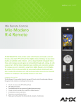
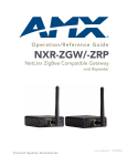
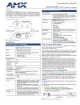
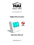
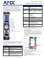
Quick Start Guide
MIO R-4 Mio Modero
Overview
®
Remote
Mio R-4 (FG148-04) Specifications (Cont.)
Modero®
The Mio
R-4 remote (FG148-04) provides custom control features,
including a full-color touchscreen, contained in an elegant handheld
rechargeable device. The R-4 communicates with a NetLinx master via a
Rear Components
wireless ZigBee® network: the device comes with installed firmware for
connecting to a ZigBee Pro network, but it can be updated with firmware to allow
it to connect to older ZigBee networks. Use TPDesign4 (TPD4) to program this
device. The R-4 uses a mini-USB port for transferring programming files.
Dimensions (HWD)
9.50 x 2.00 x .74 (241.3 mm x 50.8 mm x 18.80 mm)
Supported
Languages:
•
•
•
•
•
English
Spanish
French
Italian
German
Certifications:
•
•
•
•
•
•
FCC ID: CWU-NXR-MO
IC: 5078A-NXRMO
CE
IEC-60950
Japan Approval
Designed for ZigBee
Weight
• .45 lbs (20 g) without batteries
• .55 lbs (25 g) with batteries
Operating
Environment
• Operating Temperature: 0° to 40° C (32° to 104° F)
• Storage Temperature: -20° to 70° C (-4° to 158° F)
Included Items
• Mio-RBP Rechargeable Lithium-ion Battery (FG147-10)
Optional Keypads:
•
•
•
•
MIO-R4-KP-ITALIAN (FG148-141)
MIO-R4-KP-FRENCH (FG148-142)
MIO-R4-KP-ARABIC (FG148-143)
MIO-R4-KP-CHINESE (FG148-144)
Other AMX
Equipment
•
•
•
•
CC-USB Programming cable (FG10-5965)
Mio-RCC Charging Base (FG147-02) with power supply
NXR-ZGW (FG5791-01)
NXR-ZRP-PRO (FG5791-03)
Touch Screen
1
20
19
4
5
6
8
10
9
3
2
7
11
15
13
16
12
14
17
18
1 - Power
2 - Guide
3 - Exit
4 - Menu
5 - Information
6 - Move Up
7 - Move Down
8 - Move Left
9 - Move Right
10 - Select
11 - Volume Up
12 - Volume Down
13 - Channel Up
14 - Channel Down
15 - Last Viewed
16 - Mute
17 - Input
18 - Enter
19 - Back/Home
20 - Up/Down Touch Screen Navigation
•
•
•
•
•
Portuguese
Arabic
Russian
Greek
Simplified Chinese
•
•
•
•
Japanese
Thai
Hindi
Korean
Inserting the Lithium-Ion Battery Into The Mio R-4
To install your Lithium-Ion battery into the Mio R-4:
1.
2.
3.
4.
Numeral Keypad
• Programming Port
• Battery Door
• Rechargeable Battery Connection
Flip and turn the Mio R-4 so that the buttons are facing away from you and
the device is upside down.
Holding the device in both hands, place your thumbs on the battery door
and slide the battery door free.
Connect the terminal end of the Lithium-Ion battery to the port shown in
FIG. 2. It may be necessary to use a thin, blunt non-conductive object to
seat the battery connector fully within its port. (Note: Make sure that the
battery wires run alongside the battery in the compartment as shown in
FIG. 2. Otherwise, the wires may be damaged or the battery door may not
close properly.)
Replace the battery door, and slide it to lock it in place.
Rear view battery compartment
Programming Port
(USB)
FIG. 1 Mio Modero R-4 Remote
Touch And Tilt Sensor
The Mio R-4 wakes up upon touching either the chrome side rails or pressing a
button. If the remote goes to sleep when holding it, you can reawaken the device
by tilting it. Errant jostling, such as bumping a table on which the device rests,
will not wake the device unless you are holding it.
Lithium-Ion Battery
Correct path for
battery wires and
connector
Specifications
Mio R-4 (FG148-04) Specifications
Battery
Rechargeable Lithium-Ion
Transmission
Frequencies
• ZigBee RF wireless network
Transmission
Range
• 100 feet (30.48m).
Memory
• 32 Mbytes of FLASH
• 64 Mbytes of SDRAM
Top Components
• LED - blue backlit buttons indicate device is awake
• LCD - high resolution (240x320) 76800 pixels with
backlight and touch overlay
• Pushbuttons - the power button is red backlit; the rest
are blue backlit buttons. 29 buttons total
Rechargeable
Battery Port
Connection
FIG. 2 Rechargeable Battery and Programming Ports on The Mio R-4 Remote
Installing a Supported Language Keypad
1.
2.
3.
4.
5.
Remove the battery door (See Inserting the Lithium-Ion Battery Into the
Mio R-4) and remove the battery.
Unscrew the 6 screw points.
Turn the unit over so the buttons are facing you.
Lift the top assembly away from the PCB.
If necessary, push out the standard buttons from the front of the top
assembly.
6.
Drop in your language pad and verify the alignment with the guide posts
on the PCB.
Place the top assembly back down on the PCB and return the unit over,
exposing the 6 screw points.
Tighten the 6 screw points.
Reinstall the battery, replace the battery door, and slide the door to lock it
in place.
7.
8.
9.
Using the Programming Jack on the Mio R-4
The programming jack located on the back of the Mio R-4 (FIG. 2) is used for
communication between the device and TPDesign4. The programming jack
uses a CC-USB Programming cable, USB to mini USB (FG10-5965). You can
order the programming cable from AMX if you do not have one. While loading
your configuration file, make sure the device is situated in the charging cradle.
1.
Remove the battery door (See Inserting the Lithium-Ion Battery Into the
Mio R-4).
2.
Connect the mini USB programming cable (FG10-5965) into the
programming jack.
3.
Connect the other end of the USB cable to the USB port on your
computer.
4.
Configure the communication parameters in TPDesign4. For more information, please refer to the Mio Modero R-4 Operation/Reference Guide,
available at www.amx.com.
Device Setup Pages - Setup Menu
The Setup Menu allows you to set and check the following device features:
•
•
•
•
•
•
Project Information Functions
Remote & Display Settings
Date/Time Settings
Sound Settings
Protected Settings
Battery Settings
To enter the Setup Menu, press and hold the Input and Back buttons for 6
seconds. Navigate the setup pages using the onscreen menu selections and
up and down arrows. For more information on the Setup Menu, please refer to
the Mio Modero R-4 Operation/Reference Guide, available at www.amx.com.
Protected Settings
The Protected Settings Menu allows you to set and check the following device
features:
• Options & Recovery
• Change Passwords
• Calibrate
• System Settings
• Reboot Panel
The Protected Settings Menu may be accessed through the Setup Menu.
Accessing Protected Settings menu items requires a password confirmation.
For more information on the Protected Settings Menu, please refer to the Mio
Modero R-4 User Manual, available at www.amx.com.
Note: To access the Protected Settings Menu for the first time, you must
provide the default password: 1988.
Checking Connection Status
1.
2.
3.
Select Protected Settings in the Setup Menu.
Select System Settings in the Protected Settings Menu. If the round
button at the top right of the first page is green, the system is connected.
Select the Back button until you are out of the Setup Menu.
Joining a Wireless Network
1.
In the NXR-ZGW Browser-Based Configuration Pages, configure the
network’s gateway to allow joining. (For more information, please refer to
the NXR-ZGW/-ZRP-PRO Operator/Reference Manual, available from
www.amx.com.)
2.
Select Protected Settings in the Setup Menu.
3.
Select System Settings in the Protected Settings Menu.
4.
Press the Network Scan button. The available networks are listed below.
Use the up and down arrows to navigate the menu.
5.
Select the network by pushing it on the touch screen. A pop-up page
reading "Do you wish to connect to [Extended PAN ID number]" will
appear.
• To connect to the PAN, press the Yes button.
• To return to the Network Scan page without connecting to the PAN, press
the No button.
• If you do not make a selection within three seconds, the pop-up page will
automatically close in three seconds.
6.
Select the Back button until you are out of the Setup Menu.
Note: Due to the wireless nature of the ZigBee network, temporary interference may
prevent a command from reaching the NetLinx master. If this happens while
increasing volume, the master may receive the command to increase the volume but
not the command to stop increasing it. Therefore, programmers should consider
setting safeguards for volume control, either established volume limits or timeouts
with the NetLinx master or more interactive adjustment from the Mio R-4 (i.e., direct
volume control), to prevent issues with lost commands.
Battery Low Indicator
When the battery charge level is too low to sustain continuous operation, a
popup window will appear on the touchscreen reading “Battery Low” and then
“Battery Very Low”. If the device is still not returned to the charging cradle, it will
then shut down.
Battery Settings
1.
2.
3.
Select Battery Settings in the Setup Menu.
The battery level will be displayed on the Battery Settings Page. The
higher the number of green lights, the higher the charge.
Select the Back button until you are out of the Setup Menu.
Mio Remote Charging Base
The Mio remotes are complemented with the Mio-RCC charging base. To
charge the remote from the charging base:
1.
2.
Connect the terminal end of the power supply to the bottom external
power port on the Mio remote charging base.
Route the cable through the provided channel so that it comes out the
side of the base.
Connect the power cord to an external power source.
Place the bottom of the Mio R-4 into the charging base so the contacts on
the device are on top of the charging contacts inside the charging base.
The Power LED on the Mio R-4 blinks red to indicate it is charging and
illuminates solid red when it is done. A full charge cycle for a depleted
battery is approximately 3 hours.
Changing Passwords
3.
4.
1.
2.
3.
4.
5.
Patents
Select Protected Settings in the Setup Menu.
Select Change Passwords on the Protected Settings Menu.
Select one of the five passwords to be changed.
Enter, edit, and confirm changes to the password.
Select the Back button until you are out of the Setup Menu.
Calibrating the Mio R-4
1.
2.
3.
4.
Select Protected Settings in the Setup Menu.
Select the Calibrate button.
Touch each target as it appears on the screen.
If successfully calibrated, the Mio R-4 will return you to the Protected
Settings Menu.
Rebooting the Mio R-4
1.
2.
3.
Select Protected Settings in the Setup Menu.
Select the Reboot Panel button.
Select Reboot.
System Settings
The System Settings page of the Protected Settings provides connection
status, gateway selection, and RF link information. Use the device’s up and
down arrows to move from viewable page to page.
This product is covered by the following patents:
AMX
U.S. Patent No. D 602,858
U.S. Patent No. D 520,495
U.S. Patent No. 7,786,623
This product employs or practices certain features and/or methods of one or
more of the following patents:
SIPCO, LLC
U.S. Patent No. 7,103,511
U.S. Patent No. 6,914,893
U.S. Patent No. 7,697,492
For full warranty information, refer to the AMX Instruction Manual(s) associated with your Product(s).
5/11
©2011 AMX. All rights reserved. AMX and the AMX logo are registered trademarks of AMX.
AMX reserves the right to alter specifications without notice at any time.
3000 RESEARCH DRIVE, RICHARDSON, TX 75082 • 800.222.0193 • fax 469.624.7153 • technical support 800.932.6993 • www.amx.com
93-0148-04
REV: H