1
Digidesign ProControl
User’s Guide
Digidesign Inc.
3401-A Hillview Avenue
Palo Alto, CA 94304 USA
tel: 650·842·7900
fax: 650·842·7999
Technical Support (USA)
650·842·6699
650·856·4275
Product Information
650·842·6602
800·333·2137
Fax on Demand
1-888-USE-DIGI (873-3444)
World Wide Web
www.digidesign.com
Digidesign FTP Site
ftp.digidesign.com
Copyright
This User’s Guide is copyrighted ©1999 by Digidesign, a
division of Avid Technology, Inc. (hereafter “Digidesign”), with
all rights reserved. Under copyright laws, this manual may not
be duplicated in whole or in part without the written consent of
Digidesign.
DIGIDESIGN, AVID and PRO TOOLS are trademarks or
registered trademarks of Digidesign and/or Avid Technology,
Inc. All other trademarks are the property of their respective
owners.
All features and specifications subject to change without
notice.
PN 932707442-00 REV A 11/99
contents
Chapter 1. Introduction to ProControl . . . . . . . . . . . . . . . . . . . . . . . . . . . . . . . . . . . . . . . . . 1
About This Guide . . . . . . . . . . . . . . . . . . . . . . . . . . . . . . . . . . . . . . . . . . . . . . . . . . . . . . . . . 1
System Requirements . . . . . . . . . . . . . . . . . . . . . . . . . . . . . . . . . . . . . . . . . . . . . . . . . . . . . 2
About Fader Pack Expansion Units . . . . . . . . . . . . . . . . . . . . . . . . . . . . . . . . . . . . . . . . . . . . 3
ProControl System Contents . . . . . . . . . . . . . . . . . . . . . . . . . . . . . . . . . . . . . . . . . . . . . . . . . 3
Chapter 2. Installing ProControl . . . . . . . . . . . . . . . . . . . . . . . . . . . . . . . . . . . . . . . . . . . . . . . 5
Installation and Maintenance Guidelines . . . . . . . . . . . . . . . . . . . . . . . . . . . . . . . . . . . . . . . . 5
Software Installation . . . . . . . . . . . . . . . . . . . . . . . . . . . . . . . . . . . . . . . . . . . . . . . . . . . . . . 5
Assembling an Expanded System . . . . . . . . . . . . . . . . . . . . . . . . . . . . . . . . . . . . . . . . . . . . . 7
Dimensions (w x d x h). . . . . . . . . . . . . . . . . . . . . . . . . . . . . . . . . . . . . . . . . . . . . . . . . . . . . 8
Hardware Connections . . . . . . . . . . . . . . . . . . . . . . . . . . . . . . . . . . . . . . . . . . . . . . . . . . . . . 9
Making the Necessary Connections . . . . . . . . . . . . . . . . . . . . . . . . . . . . . . . . . . . . . . . . . . . 11
Optional Connections . . . . . . . . . . . . . . . . . . . . . . . . . . . . . . . . . . . . . . . . . . . . . . . . . . . . . 21
Fader Pack Connections . . . . . . . . . . . . . . . . . . . . . . . . . . . . . . . . . . . . . . . . . . . . . . . . . . 22
Starting Up and Shutting Down a System . . . . . . . . . . . . . . . . . . . . . . . . . . . . . . . . . . . . . . 22
Software Configuration . . . . . . . . . . . . . . . . . . . . . . . . . . . . . . . . . . . . . . . . . . . . . . . . . . . 23
QuickStart System Test and Configuration . . . . . . . . . . . . . . . . . . . . . . . . . . . . . . . . . . . . . . 25
Troubleshooting . . . . . . . . . . . . . . . . . . . . . . . . . . . . . . . . . . . . . . . . . . . . . . . . . . . . . . . . 28
Chapter 3. ProControl Basics . . . . . . . . . . . . . . . . . . . . . . . . . . . . . . . . . . . . . . . . . . . . . . . . 29
Some ProControl Terms . . . . . . . . . . . . . . . . . . . . . . . . . . . . . . . . . . . . . . . . . . . . . . . . . . . 29
Transport Switches . . . . . . . . . . . . . . . . . . . . . . . . . . . . . . . . . . . . . . . . . . . . . . . . . . . . . . 32
Level Meters . . . . . . . . . . . . . . . . . . . . . . . . . . . . . . . . . . . . . . . . . . . . . . . . . . . . . . . . . . . 39
WINDOWS Switches . . . . . . . . . . . . . . . . . . . . . . . . . . . . . . . . . . . . . . . . . . . . . . . . . . . . . 39
Time Counter Display . . . . . . . . . . . . . . . . . . . . . . . . . . . . . . . . . . . . . . . . . . . . . . . . . . . . 40
Using the Control Room Monitoring Section . . . . . . . . . . . . . . . . . . . . . . . . . . . . . . . . . . . . . 41
UNDO and SAVE Switches . . . . . . . . . . . . . . . . . . . . . . . . . . . . . . . . . . . . . . . . . . . . . . . . . 51
The Numeric Keypad . . . . . . . . . . . . . . . . . . . . . . . . . . . . . . . . . . . . . . . . . . . . . . . . . . . . . 52
Contents iii
The TRACKPAD . . . . . . . . . . . . . . . . . . . . . . . . . . . . . . . . . . . . . . . . . . . . . . . . . . . . . . . . 52
Bank Switching and Channel Scroll/NUDGE . . . . . . . . . . . . . . . . . . . . . . . . . . . . . . . . . . . . 53
ZOOM/SEL Switches . . . . . . . . . . . . . . . . . . . . . . . . . . . . . . . . . . . . . . . . . . . . . . . . . . . . . 54
KEYBOARD SHORTCUTS Section . . . . . . . . . . . . . . . . . . . . . . . . . . . . . . . . . . . . . . . . . . . . 56
F-Key Switches . . . . . . . . . . . . . . . . . . . . . . . . . . . . . . . . . . . . . . . . . . . . . . . . . . . . . . . . . 56
SCRUB/SHUTTLE Wheel . . . . . . . . . . . . . . . . . . . . . . . . . . . . . . . . . . . . . . . . . . . . . . . . . . 57
EDIT MODE, EDIT TOOL and EDIT FUNCTION Switches . . . . . . . . . . . . . . . . . . . . . . . . . . . . . 62
The Escape Switch . . . . . . . . . . . . . . . . . . . . . . . . . . . . . . . . . . . . . . . . . . . . . . . . . . . . . . 62
The Master Faders Switch . . . . . . . . . . . . . . . . . . . . . . . . . . . . . . . . . . . . . . . . . . . . . . . . . 63
DSP EDIT/ASSIGN Section. . . . . . . . . . . . . . . . . . . . . . . . . . . . . . . . . . . . . . . . . . . . . . . . . 64
The CHANNEL MATRIX . . . . . . . . . . . . . . . . . . . . . . . . . . . . . . . . . . . . . . . . . . . . . . . . . . . 64
Chapter 4. Working with Tracks . . . . . . . . . . . . . . . . . . . . . . . . . . . . . . . . . . . . . . . . . . . . . 73
Channel Fader . . . . . . . . . . . . . . . . . . . . . . . . . . . . . . . . . . . . . . . . . . . . . . . . . . . . . . . . . 73
Channel Automation Controls: AUTO Switch . . . . . . . . . . . . . . . . . . . . . . . . . . . . . . . . . . . . 79
Channel Strip Data Encoders and LED displays . . . . . . . . . . . . . . . . . . . . . . . . . . . . . . . . . . 82
The SELECT/ASSIGN Switch Section . . . . . . . . . . . . . . . . . . . . . . . . . . . . . . . . . . . . . . . . . 83
EQ IN/EDIT DYN IN/EDIT switches . . . . . . . . . . . . . . . . . . . . . . . . . . . . . . . . . . . . . . . . . . . 89
REC/RDY and MSTR REC Switches. . . . . . . . . . . . . . . . . . . . . . . . . . . . . . . . . . . . . . . . . . . 92
GROUPS: Working with Groups from ProControl . . . . . . . . . . . . . . . . . . . . . . . . . . . . . . . . . 94
Chapter 5. Recording . . . . . . . . . . . . . . . . . . . . . . . . . . . . . . . . . . . . . . . . . . . . . . . . . . . . . . 103
Basics . . . . . . . . . . . . . . . . . . . . . . . . . . . . . . . . . . . . . . . . . . . . . . . . . . . . . . . . . . . . . . 103
Starting the Recording Process . . . . . . . . . . . . . . . . . . . . . . . . . . . . . . . . . . . . . . . . . . . . 104
Record Modes . . . . . . . . . . . . . . . . . . . . . . . . . . . . . . . . . . . . . . . . . . . . . . . . . . . . . . . . 110
Setting up Cue Mixes . . . . . . . . . . . . . . . . . . . . . . . . . . . . . . . . . . . . . . . . . . . . . . . . . . . 112
Using Talkback/Listenback, and Slate/Dub (Rerecord). . . . . . . . . . . . . . . . . . . . . . . . . . . . 114
Using the DUB Function (Slate/Rerecord) . . . . . . . . . . . . . . . . . . . . . . . . . . . . . . . . . . . . . 118
Chapter 6. Editing . . . . . . . . . . . . . . . . . . . . . . . . . . . . . . . . . . . . . . . . . . . . . . . . . . . . . . . . . 121
Navigating, Zooming and Selecting with ZOOM/SEL. . . . . . . . . . . . . . . . . . . . . . . . . . . . . . 121
Navigating with the Current Location Indicator . . . . . . . . . . . . . . . . . . . . . . . . . . . . . . . . . 125
Memory Locations and Markers . . . . . . . . . . . . . . . . . . . . . . . . . . . . . . . . . . . . . . . . . . . . 125
Creating On-screen Selections . . . . . . . . . . . . . . . . . . . . . . . . . . . . . . . . . . . . . . . . . . . . . 127
Creating and Editing Regions using Capture, Separate, Trim . . . . . . . . . . . . . . . . . . . . . . . 130
EDIT TOOL Selection . . . . . . . . . . . . . . . . . . . . . . . . . . . . . . . . . . . . . . . . . . . . . . . . . . . 131
iv ProControl Guide
Grabbing/Placing and Moving Regions . . . . . . . . . . . . . . . . . . . . . . . . . . . . . . . . . . . . . . . 133
Selecting Regions . . . . . . . . . . . . . . . . . . . . . . . . . . . . . . . . . . . . . . . . . . . . . . . . . . . . . . 134
Cut, Copy, Paste and Delete . . . . . . . . . . . . . . . . . . . . . . . . . . . . . . . . . . . . . . . . . . . . . . . 135
Edit Modes: Slip, Shuffle, Spot and Grid Modes . . . . . . . . . . . . . . . . . . . . . . . . . . . . . . . . . 135
Nudging Regions . . . . . . . . . . . . . . . . . . . . . . . . . . . . . . . . . . . . . . . . . . . . . . . . . . . . . . . 136
Fades . . . . . . . . . . . . . . . . . . . . . . . . . . . . . . . . . . . . . . . . . . . . . . . . . . . . . . . . . . . . . . . 137
Editing Waveforms, MIDI and Automation with the Pencil Tool . . . . . . . . . . . . . . . . . . . . . . 138
Chapter 7. Plug-Ins and Sends . . . . . . . . . . . . . . . . . . . . . . . . . . . . . . . . . . . . . . . . . . . . . . 139
The DSP EDIT/ASSIGN Section . . . . . . . . . . . . . . . . . . . . . . . . . . . . . . . . . . . . . . . . . . . . 139
Custom Icons for Encoder Functions . . . . . . . . . . . . . . . . . . . . . . . . . . . . . . . . . . . . . . . . . 144
Assigning Plug-Ins . . . . . . . . . . . . . . . . . . . . . . . . . . . . . . . . . . . . . . . . . . . . . . . . . . . . . . 146
Plug-In Editing. . . . . . . . . . . . . . . . . . . . . . . . . . . . . . . . . . . . . . . . . . . . . . . . . . . . . . . . . 147
Bypassing Inserts . . . . . . . . . . . . . . . . . . . . . . . . . . . . . . . . . . . . . . . . . . . . . . . . . . . . . . 149
EQ and DYNamics . . . . . . . . . . . . . . . . . . . . . . . . . . . . . . . . . . . . . . . . . . . . . . . . . . . . . 153
Accessing Plug-In Pages . . . . . . . . . . . . . . . . . . . . . . . . . . . . . . . . . . . . . . . . . . . . . . . . . 155
Sends . . . . . . . . . . . . . . . . . . . . . . . . . . . . . . . . . . . . . . . . . . . . . . . . . . . . . . . . . . . . . . 156
Using the FLIP Switch . . . . . . . . . . . . . . . . . . . . . . . . . . . . . . . . . . . . . . . . . . . . . . . . . . . 160
Chapter 8. Mixing . . . . . . . . . . . . . . . . . . . . . . . . . . . . . . . . . . . . . . . . . . . . . . . . . . . . . . . . . 167
Signal Routing . . . . . . . . . . . . . . . . . . . . . . . . . . . . . . . . . . . . . . . . . . . . . . . . . . . . . . . . 167
Recording and Using Mix Automation . . . . . . . . . . . . . . . . . . . . . . . . . . . . . . . . . . . . . . . . 169
FLIP mode . . . . . . . . . . . . . . . . . . . . . . . . . . . . . . . . . . . . . . . . . . . . . . . . . . . . . . . . . . . 178
Advanced Applications . . . . . . . . . . . . . . . . . . . . . . . . . . . . . . . . . . . . . . . . . . . . . . . . . . . 188
Appendix A. UTILITY Settings . . . . . . . . . . . . . . . . . . . . . . . . . . . . . . . . . . . . . . . . . . . . . . . 191
UTILITY . . . . . . . . . . . . . . . . . . . . . . . . . . . . . . . . . . . . . . . . . . . . . . . . . . . . . . . . . . . . . . 191
Remote (Local) UTILITY Mode . . . . . . . . . . . . . . . . . . . . . . . . . . . . . . . . . . . . . . . . . . . . . . 193
UTILITY SYSTEM Settings . . . . . . . . . . . . . . . . . . . . . . . . . . . . . . . . . . . . . . . . . . . . . . . . . 195
MONITOR Settings . . . . . . . . . . . . . . . . . . . . . . . . . . . . . . . . . . . . . . . . . . . . . . . . . . . . . . 195
Listenback Settings . . . . . . . . . . . . . . . . . . . . . . . . . . . . . . . . . . . . . . . . . . . . . . . . . . . . . 197
UTILITY TEST Settings . . . . . . . . . . . . . . . . . . . . . . . . . . . . . . . . . . . . . . . . . . . . . . . . . . . 197
Contents v
Appendix B. Audio Wiring Pinout Diagrams . . . . . . . . . . . . . . . . . . . . . . . . . . . . . . . . . . 205
Appendix C. ProControl Shortcuts and Equivalents . . . . . . . . . . . . . . . . . . . . . . . . . . . 209
Index . . . . . . . . . . . . . . . . . . . . . . . . . . . . . . . . . . . . . . . . . . . . . . . . . . . . . . . . . . . . . . . . . . . . 215
vi ProControl Guide
chapter 1
Introduction to ProControl
Welcome to ProControl™, Digidesign’s
dedicated mixing and editing controller for
TDM-equipped Pro Tools systems.
Its dedicated controls allow easy navigation through Pro Tools functions, including recording, mixing, editing, grouping,
Plug-In control, and automation. Through
the use of motorized faders and data encoders (rotary knobs), automation and
mixing can be handily performed and
given visual reference. Controller movements from ProControl are immediately reflected in Pro Tools on-screen controls, and
vice versa.
About This Guide
This guide assumes you have already installed Pro Tools, and that you already have
an understanding of its features and operating conventions as explained in the
Pro Tools Reference Guide.
Conventions Used in This Guide
This guide uses the following conventions
to indicate Pro Tools on-screen menu
choices and key commands:
Convention
Action
File > Save Session
Choose Save Session
from the File menu
Control+n
Hold down the Control
key and press the n key
Option-click
Hold down the Option
key and click the mouse
button
Right-click (Windows)
Click with the right
mouse button
ProControl features a SHORTCUTS section,
which provides the following modifier-key
equivalents:
Modifier (Mac/Win)
ProControl SHORTCUT
Shift
SHIFT/ADD
Option (Mac)
Alt (Windows)
OPT(ALT)ALL
Command (c Mac)
Ctrl (Windows)
c (CTL)
Control (Mac)
Start (Windows)
CTL/CLUTCH
Chapter 1: Introduction to ProControl 1
The following symbols are used to highlight important information:
✽ User Tips are helpful hints for getting the
most from ProControl.
▲ Important Notices include information that
could affect Pro Tools session data or the performance of Pro Tools.
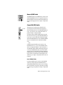
Connecting Expanded ProControl
Systems
Core ProControl systems (a single Main
Unit only) can be connected directly to the
built-in Ethernet port on all qualified Macintosh or Windows NT computers.Each
ProControl Main Unit comes supplied with
one Ethernet “Crossover” cable, which is a
special cable required when connecting a
ProControl core system
☞ Cross References point to related sections
in the Pro Tools Guides.
▲ Do not use the included Crossover Cable
with expanded systems — this cable (identifiable by its red end labels) is for core systems
only).
System Requirements
To use ProControl with a Pro Tools system,
you will need the following:
Macintosh
◆ Pro Tools 24 MIX/MIXPlus, Pro Tools 24
or Pro Tools III system, with Pro Tools software version 5.0 or higher.
◆ The ProControl Personality file (a DAE
extension), included with Pro Tools.
◆ An available Ethernet connection in the
host CPU.
◆
Audio cables for ProControl monitoring
2 ProControl Guide
Expanded ProControl systems require an
Ethernet hub (not included) and an RJ 45
Ethernet cable for each unit (included).
If a ProControl-equipped system is to be
connected to an Ethernet network (be it for
e-mail or file transferring), optimal performance can be obtained by use of an Ethernet card dedicated to ProControl communications.
Audio cables for ProControl
monitoring
Three standard DB-25 wiring harnesses are
needed if you plan on utilizing ProControl’s analog Control Room monitoring
features.
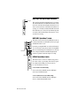
About Fader Pack Expansion Units
If you purchased one or more Fader Pack Expansion Units in addition to a main ProControl
unit, installation requirements will be slightly different. For convenience, all the instructions you need are included in Chapter 2 of this guide.
0
-2
-4
-6
-8
-10
-14
-18
-22
-26
-30
-35
-40
-45
-50
0
-2
-4
-6
-8
-10
-14
-18
-22
-26
-30
-35
-40
-45
-50
0
-2
-4
-6
-8
-10
-14
-18
-22
-26
-30
-35
-40
-45
-50
0
-2
-4
-6
-8
-10
-14
-18
-22
-26
-30
-35
-40
-45
-50
0
-2
-4
-6
-8
-10
-14
-18
-22
-26
-30
-35
-40
-45
-50
0
-2
-4
-6
-8
-10
-14
-18
-22
-26
-30
-35
-40
-45
-50
0
-2
-4
-6
-8
-10
-14
-18
-22
-26
-30
-35
-40
-45
-50
0
-2
-4
-6
-8
-10
-14
-18
-22
-26
-30
-35
-40
-45
-50
0
-2
-4
-6
-8
-10
-14
-18
-22
-26
-30
-35
-40
-45
-50
HOURS
HOURS
MINUTES
SECONDS
MS
MINUTES
SECONDS
FRAMES
FRAMES
BEATS
TICKS
FEET
BARS
0
-2
-4
-6
-8
-10
-14
-18
-22
-26
-30
-35
-40
-45
-50
0
-2
-4
-6
-8
-10
-14
-18
-22
-26
-30
-35
-40
-45
-50
1
CLR / F1
MSTR REC
F2
INS / BYP
REC / RDY
REC / RDY
INS / SEND
REC / RDY
INS / SEND
REC / RDY
INS / SEND
REC / RDY
INS / SEND
REC / RDY
INS / SEND
REC / RDY
INS / SEND
COUNTER MODE
REC / RDY
INS / SEND
SELECT
ASSIGN
AUTO
ENABLE
0
-2
-4
-6
-8
-10
-14
-18
-22
-26
-30
-35
-40
-45
-50
0
-2
-4
-6
-8
-10
-14
-18
-22
-26
-30
-35
-40
-45
-50
2
3
4
5
PRO CONTROL
6
CONTROL ROOM
BYPASS
1
-6
INS / SEND
IN/OUT/Ø
+9
2
-7
3
+8
4
-6
5
MIX TO
AUX
AUX (5-6)
STEREO MIX
TRIM 5
INFO
F3
IN / EDIT
EQ IN / EDIT
EQ IN / EDIT
EQ IN / EDIT
EQ IN / EDIT
EQ IN / EDIT
EQ IN / EDIT
EQ IN / EDIT
EQ IN / EDIT
F4
DEFAULT
DYN IN / EDIT
DYN IN / EDIT
DYN IN / EDIT
DYN IN / EDIT
DYN IN / EDIT
DYN IN / EDIT
DYN IN / EDIT
DYN IN / EDIT
SELECT / ASSIGN
-6
+9
-7
+8
-6
+9
-7
TRIM 6
SRC 1 (3-4)
INSERTS
PARAM
+8
TALKBACK
SRC 2 (5-6)
SENDS
GROUPS
PAN
MON / Ø
INPUT
OUTPUT
ASSIGN
SEND MUTE
SEND A / F
SEND D / I
SEND B / G
SEND E / J
SEND C / H
FLIP
CREATE
ENABLE
PRE / POST
PRE / POST
PRE / POST
PRE / POST
PRE / POST
PRE / POST
PRE / POST
PRE / POST
ASSIGN / MUTE
ASSIGN / MUTE
ASSIGN / MUTE
ASSIGN / MUTE
ASSIGN / MUTE
ASSIGN / MUTE
ASSIGN / MUTE
ASSIGN / MUTE
WR
WR
WR
WR
WR
WR
WR
TC
TC
TC
TC
TC
TC
TC
TC
LT
TM
AUTO
RD
LT
TM
AUTO
RD
LT
TM
AUTO
RD
LT
TM
AUTO
RD
LT
TM
AUTO
RD
LT
TM
AUTO
RD
LT
TM
AUTO
RD
SELECT
SELECT
SELECT
SELECT
SELECT
SELECT
SELECT
SOLO
SOLO
SOLO
SOLO
SOLO
SOLO
SOLO
SOLO
-7
7
DIM
ALT
MUTE
MAIN (1-6)
HEADPHONE
SELECT
8
+8
TM
RD
SELECT
6
EDIT
WR
LT
AUTO
+9
SRC 3
MONO
ALT (3-4)
PRE / POST
SUSPEND
UP
MUTE
DSP EDIT / ASSIGN
D VERB
COMPARE
CHANNEL / GROUP
MASTER
BYPASS
PREVIOUS
NEXT
ZOOM / SEL
SOLO CLEAR
CHANNEL MATRIX
VIEW
GO TO
MUTE
MUTE
AUTO SUSPEND
KICK
MUTE
SNARE
MUTE
L OVER
MUTE
R OVER
MUTE
VOX 1
MUTE
VOX 2
1
2
3
4
5
6
7
8
A
9
B
10
C
11
D
12
E
13
F
14
G
15
H
16
A
ALPHA
I
17
J
18
L
20
M
21
N
22
P
24
B (33-64)
UTILITY
Q
25
R
26
S
27
T
28
U
29
V
30
W
31
Y
Z
SHIFT
CAP LCK
#
&
DELETE
MUTE
VOX 3
GUITAR
DOWN
(1-32)
WINDOWS
DISPLAY MODE
ENABLES
VOL
PAN
+6
+6
+6
+6
+6
+6
+6
+6
+6
+6
+6
+6
+6
+6
+6
+6
+3
+3
+3
+3
+3
+3
+3
+3
+3
+3
+3
+3
+3
+3
+3
+3
O
23
MIX
MUTE
0
0
0
0
0
0
0
0
0
0
0
0
0
0
0
0
-5
-5
-5
-5
-5
-5
-5
-5
-5
-5
-5
-5
-5
-5
-5
-5
SEND LVL
SEND MUTE
OFF
PLUG-IN
-10
-10
-10
-10
-10
-10
-10
-10
-15
-15
-15
-15
-15
-15
-15
-15
-10
-15
-20
-10
-15
-20
-10
-15
-20
-10
-15
-20
-10
-15
-20
-10
-15
-20
-10
-15
-20
OPT (ALT) ALL
z (CTL)
STATUS
TRANS
PLUG-IN
MEM-LOC
7
8
9
4
5
6
1
2
3
0
MUTE
SOLO
REC / RDY SNAPSHOT
CLR ALL
*
+
ENTER
PAGES
ESCAPE
UNDO
SAVE
CAPTURE
SCRUB
SHUTTLE
.
MASTER FADERS
NUDGE
EDIT FUNCTION
-10
-15
-20
-20
-20
-20
-20
-20
-20
-20
-30
-30
-30
-30
-30
-30
-30
-30
-30
-30
-30
-30
-30
-30
-30
-30
-40
-40
-40
-40
-40
-40
-40
-40
-40
-40
-40
-40
-40
-40
-40
-40
-50
-50
-50
-50
-50
-50
-50
-50
-50
-50
-50
-50
-50
-50
-50
-50
-60
-60
-60
-60
-60
-60
-60
-60
-60
-60
-60
-60
-60
-60
-60
-60
SHUFFLE
SLIP
TRIM
SELECT
SPOT
GRID
CUT
PENCIL
AUDITION
COPY
DELETE
SEPARATE
IN
OUT
POST
LOOP
REC
QUICK
PUNCH
PASTE
EDIT TOOL
BANK SELECT
-20
ON
LINE
SHORTCUTS
SHIFT / ADD
CTL / CLUTCH
C (65-96)
D (97-128)
PARAM
EDIT MODE
TRIM
READ
/
EDIT
X
32
SPACE
BANKS
STATUS
SELECT
LATCH
=
CL
K
19
AUTOMATION
MODE
WRITE
TOUCH
GRAB
EXT
TRANS
PRE
LOOP
PLAYBACK
TALK
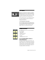
BACK
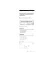
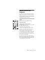
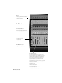
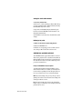
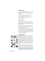
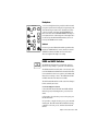
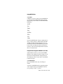
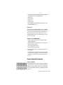
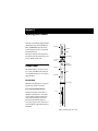
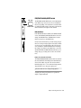
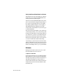
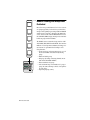
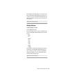
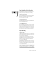
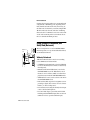
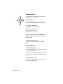
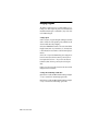
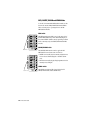
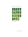
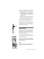
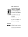
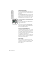
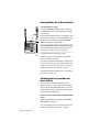
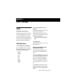
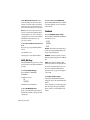
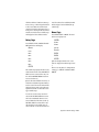
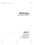
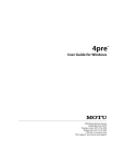
A Fader Pack Expansion Unit, left, and a Main Unit, right
ProControl System Contents
Main Unit
◆
ProControl Main Unit
◆ Pro Tools 5.0 (or later) software upgrade
package, containing ProControl firmware
Fader Pack
ProControl Fader Pack Expansion Units include:
◆
ProControl Fader Pack Expansion Unit
◆
ProControl Users Guide
◆
Fader Pack Installation Guide
◆
ProControl Tutorial CD-ROM
◆
15' Standard Ethernet cable
◆
15' Ethernet crossover cable
◆
15' Standard Ethernet cable
◆ Ethernet loopback connector (for Ethernet testing)
◆ Ethernet loopback connector (for Ethernet testing)
◆
◆
◆ Pair of chassis connection brackets/instructions
AC power cable
◆
Spare screws for connection brackets
Registration card
◆
AC power cable
◆
Registration card
Chapter 1: Introduction to ProControl 3
4 ProControl Guide
chapter 2
Installing ProControl
This chapter covers ProControl installation
and setup:
• Installing software
• Assembling an Expanded System
• Connecting ProContror
• Starting up your system
• Configuring Pro Tools for ProControl
• Testing your system
• Troubleshooting
Moving ProControl units
To avoid damage, never set a unit on its
face or rear panel. When moving expanded
systems, never attempt to turn the units
upside down as this can put undue stress
on the mounting brackets.
Software Installation
Basic Instructions (All systems)
Installation and
Maintenance Guidelines
ProControl can be mounted in studio furniture or set on a table top. Wherever you
decide to put ProControl, be sure to observe the following guidelines:
• Do not block the front and back vents
• Do not remove the feet
Cleaning a ProControl unit
If you need to clean the ProControl top surface, apply a non-bleach cleaning solution
to a cloth or paper towel, then carefully
wipe the surface. Do not use abrasives or
any cleaning solution that contains bleach.
The Pro Tools Installer automatically installs all ProControl software as part of the
Easy Install option. If you have not yet installed Pro Tools, stop here and refer to the
Pro Tools System Installation Guide. Follow the instructions there to do an Easy Install of Pro Tools.
With each Pro Tools release, any new ProControl firmware is included in the ProControl personality file so you can update
ProControl easily. See “ProControl Firmware” on page 24.
If you have already installed Pro Tools but
performed a Custom Install, do the following to make sure the ProControl software is
correctly installed:
Chapter 2: Installing ProControl 5
1 Insert the Pro Tools Installer disc into the
To install the Digi Driver for ProControl
Ethernet communication:
CD-ROM drive and launch the Pro Tools
Installer.
1 Open the Network Control Panel (Start >
Settings > Control Panels > Network).
2 Choose Custom Install.
2 Display the Protocols tab
3 Select ProControl and click Install.
3 Click Add, then select Have Disk.
On Macintosh
4 Enter the full pathname to the DigiDriver
(for example, C:\Program Files\Digidesign\DAE\Controllers\Procontrol)
To install ProControl software:
The Installer places the ProControl Personality file in the Controllers folder. The Controllers folder is located within in the DAE
Folder, which is inside the System Folder.
On Windows NT
The Installer puts the following files in the
Digidesign\DAE\Controllers\Procontrol
directory.
DigiNet.sys
DigiNet32.dll
oemsetup.inf
Procontrol.dll
Procontrol.dll.rsr
Procontrol_M.dll
5 Assuming you enter the correct path
name, Windows will select and display
“NDIS 3.0 Packet Driver v3.5”.
6 Click OK to choose, then close the Net-
work control panel.
7 At the Windows prompt, click Yes to re-
start the computer.
To remove the ethernet driver:
1 Open the Network Control Panel.
1 Display the Services tab.
2 In the list of Services, select DigiNet.
3 Click Remove, then click Yes to confirm
that you want to remove the driver.
Additional software
instructions for Windows NT
4 Close the Network Control Panel and restart the computer.
Windows NT requires an additional software installation for ProControl.
To change the ethernet port:
Before you can perform this installation,
the computer’s Ethernet port (either builtin or expansion card) must already be enabled and running. Consult the documentation that came with the Ethernet card (if
any), the Windows NT documentation or
the documentation that came with the
CPU if you have not yet enabled an Ethernet port.
Bindings tab.
6 ProControl Guide
1 In the Network Control Panel, select
2 Select and expand DigiNet.
3 Select Ethernet port and enable the port
to which ProControl is connected.
4 Disable other ports.
5 Click OK and then click Yes at the
prompt to restart.
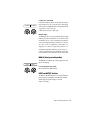
Assembling an Expanded System
Attaching Fader Packs to a Main Unit
Expanded systems can be bracketed together or left freestanding, depending on your preference.
You can arrange units in any physical order; putting one
Fader Pack at the far left, the Main Unit in the middle, and
Fader Packs 2 and 3 to the right, or place the main unit at
the far left. The most common arrangement is one where
the main unit remains centered, as close to the “sweet spot”
of the mix environment as possible.
If you decide to leave the units free-standing, you can skip
this section and proceed to “Hardware Connections” on
page 9.
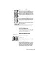
Front
Rear
If you want to bracket the units together for greater stability
or flush mounting, do the following:
To attach a Fader Pack to a Main Unit using the included
mounting brackets:
1 Locate the two mounting brackets included with the
Fader Pack.
2 Make sure the units are NOT plugged in or powered on.
3 Remove the appropriate side panel from the main unit by
removing the six screws (four longer screws, and two
shorter ones—extras were included with the unit). Note
where the longer screws are used. If you plan to reattach the
side panel to your system, set the screws aside.
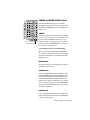
R
!
NE PAS OUVRIR
Removing the side panels
4 Place the ProControl main and Fader Pack units on a table
and position the units so their front or rear panels hang
over the edge of the table. If necessary, prop the unit up to
gain access to the brackets.
Chapter 2: Installing ProControl 7
5 Remove the bracket screws from the underside and back
panels of the Main Unit and Fader Packs.
6 Align the rear bracket with the holes in either the Main
Unit or a Fader pack, and use the same screws to attach the
rear bracket to both units.
▲ Use care if you reposition the units while only one bracket is
attached.
7 At the front panel mounting location, remove the six
mounting screws (three on the Main Unit, three on the
Fader Pack).
8 Align the front bracket with the holes in the Main Unit
and Fader Pack, and use the six screws you removed to attach the front bracket to both units.
9 After attaching both mounting brackets, be very careful
when moving the units. Do not carry an expanded ProControl system face down.
10 You can reattach the side panel (removed from the main
unit) to the outside of the Fader Pack. If you do, be sure to
put the long screws and the short screws in their proper locations when reattaching the side panels
Dimensions (w x d x h)
ProControl Main Unit with Side Caps:
30.71"w x 25.04"d x 7.10"h
78cm w x 63.6cm d x 18cm h
ProControl Main Unit without Side Caps:
28.16"w x 25.04"d x 7.10"h
71.5cm w x 63.6cm d x 18cm h
ProControl Fader Expansion Pack:
15.13"w x 25.04"d x 7.10"h
38.4cm w x 63.6cm d x 18cm h
✽ Detailed dimension drawings are available on the Digidesign
website.
8 ProControl Guide
Hardware Connections
This section begins with a description of ProControl back
panel connectors, followed by instructions for making all
the necessary connections between ProControl and the
CPU/Pro Tools system.
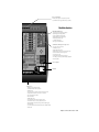
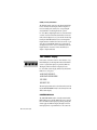
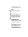
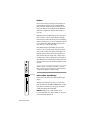
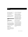
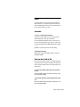
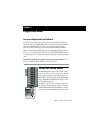
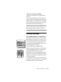
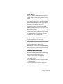
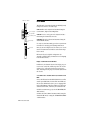
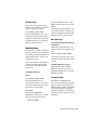
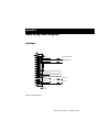
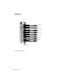
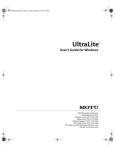
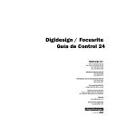
ProControl Main Unit Back Panel
1
2
3 4
5
Back panel connectors of a Main Unit
6
7
8
1. Audio Input 1
This DB-25 connector carries the following input signals:
External Listenback Mic In
External Talkback Mic In
Aux in, right and left
2. Audio Input 2
This DB-25 connector carries the following input signals:
Source 3 In, right and left
Source 2 In, right and left
Source 1 In, right and left
Main In, right and left
3. Audio Output
This DB-25 connector carries the following ProControl output signals:
Aux Out, right and left
Control Room Alt Out, right and left
Slate/Dub Out, right and left
Control Room Out, right and left
Chapter 2: Installing ProControl 9
4. Ext Talkback and Ext Listenback Trim
These two trim pots are used to adjust the input level of the
optional External Talkback/Listenback mic inputs. Be very
careful when moving ProControl to avoid breaking these
knobs—do not stand the unit up on its back panel without
making sure the trim pots are out of harm’s way.
5. Ext Mouse, MIDI and Com Port
The Ext Mouse connector lets you use a standard Windowscompatible mouse instead of the built-in ProControl Trackpad. Any “Microsoft Mouse” (3-byte)-compatible mouse
can be attached to this connector.
The MIDI In/Out and Com ports are provided to support future features of ProControl/Pro Tools, as well as for certain
factory diagnostics. You should not connect anything to
these ports.
6. Ethernet
Each ProControl unit contains a single Ethernet port.
7. SW 1 and SW 2
These two 1/4” jacks provide footswitch-control for
Pro Tools play/stop, record (punch in/out), and remote talkback on/off. Polarity is selectable for these switch ports, allowing you to use virtually any momentary footswitch to
control these functions.
8. Power
This connector accepts a standard AC power cable. ProControl and Fader Packs are auto power-selecting (100V to
240V) and will automatically work with a standard modular
cable to connect to AC power receptacles in any country.
10 ProControl Guide
Making the Necessary
Connections
Ethernet for Expanded ProControl
Systems
▲ If you have an expanded ProControl system,
Step 1. Power Connection
The ProControl back panel provides an IEC
standard AC receptacle. This connector accepts a standard AC power cable.
■ Plug one end of a power cord (included
with ProControl) into the ProControl AC
receptacle and plug the other end into a
power source such as a power strip or wall
outlet.
Step 2. Ethernet Connections
ProControl communicates with Pro Tools
using Ethernet. This connection uses a
standard RJ45, 10Base-T connector. Ethernet connection requirements differ for core
systems (one Main Unit only) and for expanded systems (one Main Unit with one
or more Fader Packs):
Ethernet Connection for Core
ProControl Systems
The Ethernet cables supplied with ProControl include the red-labeled “crossover” cable for Main Unit-only systems.
To make Ethernet connections for a
ProControl Core System:
you need one standard RJ45 cable (included
with each Main unit and Fader Pack) and an
Ethernet hub (not included, but available from
most electronic supply and computer stores).
To connect an expanded ProControl System:
1 Install the Ethernet hub according to its
instructions, and verify that it is functioning properly before proceeding.
2 Connect one end of a standard RJ45 ca-
ble to a port on the Ethernet hub (do not
use any ports labelled/intended for Uplink
functions). Do not use the crossover cable
supplied by Digidesign with ProControl (it
has red heat-shrink at both ends)—this cable will not function in an expanded system.
3 Connect the other end of the RJ45 to the
ETHERNET port on the back of the Main
Unit.
4 For each Fader Pack, use another RJ45 ca-
ble to make a connection between another
hub port and the Fader Pack’s ETHERNET
port. Cabling sequence does not matter, as
it can be configured from within Pro Tools.
The supplied red-wrapped cable will not
function (and should not be used) with expanded systems.
1 With ProControl positioned, take the in-
cluded crossover Ethernet cable (with the
red heat-shrink labels) and connect one
end to the Ethernet port on the back panel
of ProControl.
2 Connect the other end of the cable to the
appropriate Ethernet port on the CPU.
Chapter 2: Installing ProControl 11
About ProControl and Ethernet
Performance
This section presents some general Ethernet concepts that can help you optimize
system performance.
ProControl, Ethernet and Network Traffic
If the system is already connected to an
Ethernet network, moderate network traffic (such as basic email) should not impact
ProControl/Pro Tools communication. For
optimal performance, create a dedicated
Ethernet network for ProControl (do not
share the Ethernet port between ProControl and other active network functions
such as email, file transfers or other). Refer
to the documentation that came with the
CPU or Ethernet hub for more information
about Ethernet networks.
Most times you can use the built-in Ethernet in your computer. For better performance, you might want to use an additional Ethernet 10baseT card (which takes
up an additional slot in the CPU). There are
combined 10/100 BaseT hub/bridges
readily available that, when properly configured, can support ProControl over
10baseT and other network traffic over
100baseT simultaneously.
ProControl then acts as an Ethernet
“server.” Pro Tools acts as an Ethernet “client,” and Pro Tools clients can “listen” to
servers.
12 ProControl Guide
Ethernet Descriptions
ProControl uses Ethernet phase 1, Type
0x885F packets, and can co-exist with
TCP/IP (and other) networking protocols
used on standard Mac/PC Ethernet networks. The included Crossover Cable (red
heat shrink ends) provides a dedicated
“network” for a core system.
Remote Control
ProControl can “see” any Ethernet client
(card) connected to a network.
Because of this Ethernet implementation,
you can set up a wide range of creative and
practical configurations such as the use of a
single ProControl system controlling different Pro Tools systems (though not simultaneously) without reconnecting.
Separate Zone Recommended for
Optimal Performance
ProControl and its Ethernet implementation are designed to operate while you are
performing general purpose tasks such as
email. If you are using additional Ethernet
ports for network tasks while using ProControl, performance will be improved by
creating a dedicated server zone for ProControl. Refer to the operating system and
Ethernet documentation for details.
Step 3. Audio Connections
ProControl offers a great deal of flexibility
for routing audio in the studio. While audio connections to and from ProControl
are not necessary for ProControl to operate
Pro Tools functions, they are required to
use the extensive analog control room
monitoring features of ProControl.
All mixing, recording and digital signal
processing always takes place in the
Pro Tools mix environment. The ProControl Control Room section is capable of
handling virtually all control room audio
needs, including A/B speaker selection,
mono/confidence, talkback/listenback,
and more.
Analog audio connections to ProControl
are made through three 4-40 Americanstandard, male panel-mount DB-25 connectors on the rear of the Main Unit (labeled Audio Input 1, Audio Input 2, and
Audio Output).
For wiring pinout diagrams for ProControl
AUDIO INPUT 1, AUDIO INPUT 2 and AUDIO OUTPUT ports, see Appendix B: Audio
Wiring Pinout Diagrams.
Input/Output Overview
Two eight-channel input connectors supply ProControl with Pro Tools audio interface output signals, additional sources and
external signal busses.
One eight-channel output connector supplies ProControl output for speakers/monitors, alternate speakers, cue mix systems,
mastering decks/machines, Pro Tools inputs (for recording for slating/dub and rerecord), a patchbay or any other destination.
DB-25 cables (or “harnesses”) are available
through many vendors (contact your
Digidesign dealer for information). When
considering the connector format, think
about which audio interfaces you will be
dedicating to ProControl I/O (888-series interfaces have XLR, while the 882-series are
hi-z 1/4” inputs and outputs). To bring the
signal to a patchbay, have it wired with no
connector “pigtails” and terminate this
snake to the patchbay. For maximum flexibility, buy appropriate DB-25 connectors
and the necessary cables (multi-pair snake
or individual “pairs”) and wire from
scratch.
About Stereo and Surround
Modes
ProControl can operate in stereo or surround
mode. The mode you choose will determine the I/O connections. The following
tables list the suggested input and output
connections for Stereo and Surround monitor mode.
Chapter 2: Installing ProControl 13
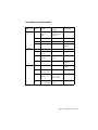
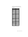
Stereo Monitor Mode Input and Output
Audio Connector
Input 1
Input 2
Output
14 ProControl Guide
Channels
Signal/bus
Input Source/
Output Destination
1&2
LB/TBMICIN
Listenback
Talkback
from an external Listen- TALKBACK
back (ch1) and or Talkback (ch2)
3&4
n/a
5&6
n/a
7&8
AUX IN L/R
cue mix
AUX (5-6);
MIX TO AUX
1&2
SRC3 IN L/R
Source 3 In
from CD, DAT, VCR or
other source
SRC 3
3&4
SRC2 IN L/R
Source 2 In
from CD, DAT, VCR or
other source
SRC 2 (5-6)
5&6
SRC1 IN L/R
Source 1 In
from CD, DAT, VCR or
other source
SRC 1 (3-4)
7&8
MAIN IN L/R
Pro Tools stereo mix
MAIN (1-6);
STEREO MIX
1&2
AUX OUTL/R
headphones/cue
system
AUX (5-6);
MIX TO AUX
3&4
CRAOUTL/R
Control room Alt Out
to control room alternate ALT (3-4);
speakers
ALT
5&6
SLOUTL/R
Slate/dub out
to Slate/dub bus
(Pro Tools inputs/
channels) or other
TALKBACK
7&8
CRM OUT L/R
Control room Main Out
to control room main
speakers
MAIN (1-6)z
Control Room access
Surround Monitor Mode Input and Output
Audio Connector
Input 1
Input 2
Output
Channel
Signal/bus
Input Source / Output
Destination
1&2
LB/TBMICIN
Listenback
Talkback
from an external
TALKBACK
Listenback (ch1) and or
Talkback (ch2)
3&4
n/a
5&6
n/a
7&8
AUX IN L/R
1&2
n/a
3&4
Control Room access
cue mix
AUX (5-6);
MIX TO AUX
SRC2 IN L/R
Source 2 In
Center/Sub
SRC 2 (5-6)
5&6
SRC1 IN L/R
Source 1 In
Surround/Satellite
channels
SRC 1 (3-4)
7&8
MAIN IN L/R
front L/R
MAIN (1-6);
STEREO MIX
1&2
AUX OUTL/R
to Center/Sub
AUX (5-6);
MIX TO AUX
3&4
CRAOUTL/R
Control room Alt Out
to surround Ls/Rs
ALT (3-4);
ALT
5&6
SLOUTL/R
Slate/dub out
to Slate/dub bus
(Pro Tools inputs/
channels) or other
TALKBACK
7&8
CRM OUT L/R
Control room Main Out
to front left/right
speakers
MAIN (1-6)z
Chapter 2: Installing ProControl 15
Connections for Stereo Mode
Main Inputs from Pro Tools
To connect Pro Tools main L/R mix (Stereo
Mix mode):
■ Connect Pro Tools main stereo outputs
(usually audio interface Outputs 1 & 2) to
the ProControl MAIN IN Left/Right inputs
(Audio Input 2, channels 7 & 8).
Alternate Source Inputs
In addition to the main L/R input bus, ProControl provides three pairs of alternate
“source” inputs. (Cue/headphone mixes
can be accommodated in a different way,
as explained in “Connecting Cue Mix systems” on page 16.)
For alternate source input in Stereo Monitoring mode from tape machines, CD players, or other:
■ Connect alternate source outputs to the
ProControl SOURCE 1, 2 or 3 inputs. These
input signals are carried on the Audio Input 2, on channels 1/2, 3/4 and 5/6, respectively. They can then be selected for
monitoring using the ProControl SRC 1,
SRC 2 and SRC 3 switches.
When in Stereo monitor mode, you can listen to any of these sources at anytime, and
you can configure ProControl for “single”
or “multi” source input monitoring.
16 ProControl Guide
About Multi-source Stereo and
“Single”-source Stereo Monitor
Modes
ProControl can operate in either of two Stereo monitor modes, Multi or (single source)
Stereo. The latter (single source) is the default Stereo operation mode. In SingleSource Stereo monitoring mode, only one
source input can be auditioned at a time.
In Multi-Source Stereo monitoring mode
(selectable from the UTILITY menus) ProControl lets you listen to one, two or three
Source inputs simultaneously with the
main input sources (all inputs remain active until disengaged).
Connecting Cue Mix systems
In Stereo Monitoring mode, the ProControl AUX OUT output bus and AUX (5-6)
level control are intended to be used for talent/cue mix outputs.
1 Connect the appropriate Pro Tools out-
puts (the output pair which you have designated as the cue mix bus) to the
ProControl AUX IN left/right input (Audio
Input 1, channels 1 & 2).
2 Connect the ProControl AUX OUT L/R
outputs (Audio Output channels 1 & 2) to
the studio headphone (cue) monitoring
system. This signal’s level can be controlled
from the ProControl AUX (5-6) level control.
Pro Tools Cue Mix considerations
One way to set this up is to use a Pro Tools
Send bus (mono or stereo) as the cue mix
feed and route the send to a Pro Tools output pair. By patching that Pro Tools output
to the ProControl AUX IN Left/Right bus,
the overall level of the cue mix can be controlled directly from the ProControl Control Room section.
While in Stereo monitoring mode, you can
also use the MIX TO AUX switch in the ProControl control room section to send the
main stereo signal (Pro Tools main stereo
output bus or whatever signal is patched to
the ProControl MAIN IN L/R bus) to AUX
OUT.
✽ If you plan to use ProControl in stereo mon-
itoring mode and expect to be setting up cue
mixes, you will definitely want to learn about
ProControl FLIP mode, MUTE/DIM switches,
Control Room preferences, and Slate/Dub/Rerecord capabilities.
Talkback/Listenback Input
connections
Talkback and Listenback options are provided in ProControl, including a built-in
Talkback mic.
Talkback Allows those in the control room
to be heard in the cue mix or any output
destination (live room speakers, machine
room communication line, or other). You
can use the internal talkback mic or an external mic for this purpose.
Listenback An option that is very useful
when overdubbing talent in the studio that
does not use an open mic for recording (for
example, a synthesizer overdub that is be-
ing recorded directly, or a guitar overdub
where the cabinet is mic’d but nobody
needs a vocal mic for singing). By setting
up a microphone in the tracking room and
routing it to the ProControl Listenback bus
input, direct two-way communication between the control room and the talent is
ensured. The Listenback bus can be slaved
to follow Talkback (meaning, pressing the
TALKBACK switch also opens the Listenback channel).
In addition, the Talkback signal can be fed
to the ProControl Slate/Dub (Rerecord)
bus. This capability makes it very easy to
not only record basic slate information using Talkback, but also makes it possible to
quickly record reference vocals or other
spur-of-the-moment ideas without having
to first set up a microphone and adjust levels.
Using external Talkback or Listenback
ProControl provides +15V in a standard
phantom power arrangement to power
condenser mics. While this voltage rating
does not match the industry standard of
+48V, it is adequate to power most any
popular condenser microphone. In addition, this phantom power is always on (you
can’t disable it). This should not be a cause
for concern; dynamic microphones will
work fine, and will not be damaged by inserting them into the Talkback or Listenback microphone inputs.
▲ Do not connect ribbon microphones to
these powered inputs, as ribbon microphones
may be damaged by connecting them to any
phantom power source.
Chapter 2: Installing ProControl 17
To connect an external Talkback or
Listenback mic:
■ Connect your external Listenback mic
signal to the ProControl External Listenback Mic In (found on the Audio Input 1
connector, channel 1).
■ For an external Talkback mic, connect
the appropriate signal to the ProControl
External Talkback Mic In (Audio Input 1,
channel 2).
■ Connect your secondary reference monitors/amp (if any) to the CONTROL ROOM
ALT OUT left/right outputs (Audio Output,
channels 3 & 4). This will allow you to select and adjust the level of this set of speakers using the ProControl ALT (3-4) source
switch and level control.
☞ For cue/headphone systems, use the AUX
OUT L/R bus as explained in “Connecting Cue
Mix systems” on page 16.
EXT TALKBACK and LISTENBACK TRIM
There are also trim pots labeled “EXT
TALKBACK TRIM” and “LISTENBACK
TRIM” which may be used to trim the levels of either an external talkback mic or listenback mic.
Because ProControl includes a Slate/Dub
(Rerecord) bus, you can route and record
the signals from the Talkback bus to
Pro Tools audio interface inputs, where the
audio signals can be recorded to a disk track
(or any appropriate destination). For details about connections for Slate/Dub/Rerecord, see “Slate/Dub (Rerecord) Output
Connection” on page 18.
Slate/Dub (Rerecord) Output
Connection
The SLATE/DUB left/right output bus (Audio Output, channels 5 & 6) carries the signal from the ProControl Slate/Dub (Rerecord) bus. Slate/Dub (Rerecord) lets you
record Talkback audio in Pro Tools (or any
recording device). Once you’ve connected
the Slate/Dub output to a Pro Tools audio
interface input, any ProControl input
source (Talkback, Listenback, Main stereo
mix, source 1, 2 or 3) can be routed to the
Slate/Dub bus. This makes it very simple to
record slates, for example.
To use the Slate/Dub bus:
Output Connections for Stereo
Mode
Main and Alternate Speaker Connections
■ Connect your main (primary) control
room monitor/amp to the ProControl
CONTROL ROOM OUT left/right outputs
(Audio Output, channels 7 & 8). These
speakers will now be under the control of
the MAIN (1-6) level control.
18 ProControl Guide
■ To bus Slate/Dub (Rerecord) to Pro Tools,
connect ProControl Slate/Dub Out
Left/Right (Audio Output channels 5 & 6)
to an available input pair of a Pro Tools audio interface (or a DAT machine or other
recording device). If you only plan to
record mono Talkback Slate audio, you can
connect one of the Slate/Dub outputs (this
saves one Pro Tools input for other purposes).
For even greater flexibility, wire the
SLATE/DUB OUTPUT to a patch bay. This
will make it easier to switch between
Pro Tools and, for example, a DAT machine
for recording the Slate/Dub output signals.
Configuring this bus for Talkback/Listenback bus recording can be done from the
ProControl switches “live” or using the
UTILITY menus. Slate/Dub/Rerecord features are explained in Chapter 5: Recording.
Surround Monitoring Mode
Connections
About Surround Mode
ProControl offers a multi-channel surround monitoring mode to feed four- or
six-channel monitoring systems.
While Pro Tools itself does not yet support
multi-channel/surround panning, you can
mix and monitor in LCRS, 5.1 or other formats with ProControl. You can achieve
multi-channel output by utilizing
Pro Tools send busses as described in the
following sections.
Multi-channel/Surround Monitoring in
Pro Tools
You can monitor and mix in a type of
multi-channel surround mode directly
within Pro Tools using Sends.
In this setup, Send level/pan determine the
“placement” of an audio track. This technique works best for static mix elements
(meaning, tracks that stay in one position
in the surround mix field and do not need
to be pan automated).
The next section provides possible LCRS
and 5.1 setups.
Four-channel Pro Tools mix
Example four-channel/LCRS Pro Tools mixer
setup
1 Insert one stereo and two mono pre-fader
sends on every track in the surround mix.
2 Use the stereo send to bus or “pan” audio
to a pair of Pro Tools audio interface outputs. This bus will carry the front left/right
channels.
3 Use one mono send to bus/pan audio to
a single Pro Tools audio interface output,
for the (mono) surround channel.
4 Use the other mono send to bus/pan au-
dio to another mono Pro Tools audio interface output, to carry the center channel
signal.
5 For a discrete two-channel stereo mix,
use the Track Output selectors to bus tracks
to a pair of Pro Tools outputs.
ProControl Input Connections: 4ch/LCRS
■ Connect the front left/right bus outputs
to ProControl Main In Left/Right (Audio
Input 2, channels 7 & 8).
Connect the surround bus output to ProControl Source 1 In Left (Audio Input 2,
channel 5).
■
■ Connect the center bus output to ProControl Source 2 In Left.
Chapter 2: Installing ProControl 19
✽ It is not necessary to create/use stereo Aux
Input tracks and configure them to control the
surround channel outputs (stems) though it
may seem logical to do so. This is because
Aux Input fader and mute controls would be duplicating ProControl Control Room monitor
level and source selection controls. See “Using the Control Room Monitoring Section” on
page 41.
You can assign all four (or six) Pro Tools
Sends to all channels and use Send Level or
Send Bypass/mute to control the mix. Alternatively, since often times there are elements that will only appear in certain
channels (LFE signals being the most obvious example) you can conserve mixer DSP
by inserting “surround sends” on an asneeded basis.
Six-channel (5.1) Pro Tools mix
ProControl Output Connections: 4ch/LCRS
Control Room Main Out Left/Right (Audio Output channels 7 & 8) to the front
left/right channel monitor amp/speaker inputs.
■
■ Control Room Alt Out Left (Audio Output channel 3) to the surround channel
monitor system input.
Aux Out Left (Audio Output channel 1)
to the center channel monitor input.
■
When configured in this way, master control room monitoring level is controlled using the MAIN (1-6) rotary knob in the Control Room section. Surround channel
monitoring level is controlled using ALT
(3-4), and center channel monitoring level
by AUX (5-6). These are monitoring levels
only.
If you use the same pair of speakers for
both stereo-mix left/right and surroundmix front left/right (or Dolby Lt/Rt), it
might seem practical to use the Track Output Selector to get all tracks to the front
left/right surround bus. While you can certainly do this (and may need to, depending
on available DSP resources) the combination of pre-fader sends and the channel
fader provides additional level control and
flexibility.
20 ProControl Guide
To configure Pro Tools for a six-channel, sendbased mix:
1 Insert two stereo sends and two mono
sends on each track (or, as needed depending on the audio material and where it
needs to be placed).
2 Use one stereo send to bus to a pair of au-
dio interface output channels. This bus will
carry the front left/right channels.
3 Use the other stereo send to bus to an-
other pair of audio interface output channels. This bus will carry the surround
left/right channels.
4 Use one of the mono sends to bus to a
discrete Pro Tools audio interface output
channel. This will carry the center channel.
5 Use the other mono send to bus to a discrete Pro Tools output, for the sub or LFE
channel.
ProControl Input Connections
Connect the front left/right outputs to
ProControl Main In Left/Right (Audio Input 2, channels 7 & 8).
■
■ Connect the surround left/right channel
outputs to ProControl Source 1 In
Left/Right (Audio Input 2, channels 5 & 6).
Connect the center and sub channel outputs to ProControl Source 2 In Left/Right
(Audio Input 2, channels 3 & 4, respectively).
■
ProControl Output Connections
■ Connect Control Room Main Out
Left/Right to the front left/right monitor
input channels.
■ Connect Control Room Alt Out
Left/Right to your surround left/right monitor input channels.
Connect Aux Out Left/Right to your center and sub monitor input channels.
■
When properly configured and connected,
ProControl will give you monitoring level
and in/out control over each pair of surround stems using the control room section.
About Source 1, 2 and 3 in Surround Mode
In Surround mode, the SOURCE 1 and
SOURCE 2 inputs are used for surround
and center/sub channel inputs. Source 3 In
is not used. To integrate other devices
while working in Surround mode, patch
the output of the device (DAT deck, or
other) to available inputs on your Pro Tools
audio interfaces.
Optional Connections
(All Modes)
Headphone
ProControl provides a stereo headphone
jack on the front panel. A discrete feed of
the main stereo ProControl mix, headphone level is set from the Headphone
knob in the Control Room section.
To connect headphones in a fixed installation (custom cabinets), you can use a rightangle stereo phone plug.
Headphone output follows Control Room
MONO, but not control room MUTE or
DIM functions. This jack is not meant to
feed a cue system, but to allow a single pair
of headphones to be connected directly to
ProControl to monitor in private.
Footswitch
The SW 1 and SW 2 jacks can be assigned to
any of three available Footswitch functions:
• Play/stop
• Record (punch-in/punch out)
• Remote Talkback on/off
Both footswitch inputs’ polarity is selectable to support virtually any available momentary footswitch.
The function and polarity of the footswitch
jacks SW 1 and SW 2 are configured using
the ProControl UTILITY menus. Press
UTILITY > PREFS > SWITCH 1 (or
SWITCH 2) and configure the polarity and
functions. (See Appendix A: UTILITY Settings for more information on UTILITY.)
Chapter 2: Installing ProControl 21
External Mouse
The EXT MOUSE port can be used to attach
a Windows-compatible mouse directly to
ProControl. You can then use a mouse instead of the built-in Trackpad (you can not
use both an external mouse and the Trackpad simultaneously).
Unused Ports
COM Port
The COM PORT connectors on the back of
ProControl is used only for factory diagnostics.
Starting Up and Shutting
Down a System
Pro Tools consists of several components
that have to be turned on and off individually. For these devices to communicate
properly, start up and shut down your system in the following order:
Start your Pro Tools System in this order:
1 Turn on external hard drives first. Wait
10 to 15 seconds for them to come up to
speed.
2 Turn on ProControl, then any Fader
Packs.
MIDI Connections
3 If you plan to work with MIDI equip-
ProControl uses Ethernet for all communications to and from the host CPU. The
MIDI ports are currently not supported.
ment, turn on MIDI interface and other
MIDI devices.
4 Turn on Audio Interfaces.
5 Turn on computer.
6 Turn on monitoring speakers/system.
Fader Pack Connections
Shut down Pro Tools in this order:
Fader Packs only require power and Ethernet connections.
1 Turn off monitoring speakers/system.
Power Connections
3 Shut down computer.
1 Plug one end of a power cord (included)
into the Fader Pack AC receptacle.
4 If using MIDI equipment, turn off MIDI
2 Plug the other end into a power source
5 Turn off ProControl (its outputs mute
such as a power strip or wall outlet.
during power-up/down).
2 Turn off Audio Interfaces.
interfaces, controllers, or other.
6 Turn off external hard drives.
Ethernet Connections
With ProControl positioned, use a standard RJ-45 cable and connect the Fader
Pack Ethernet port to an available port on
your Ethernet hub.
■
The rest of the ports on Fader Packs are inactive and should be left unused.
22 ProControl Guide
✽ ProControl features many system diagnos-
tics and recalibration tests that you can perform at startup using special key commands.
Refer to the Appendix of this manual for complete information on all of these utility functions.
Software Configuration
Establishing Communication between
ProControl and Pro Tools
Communication between ProControl (and
Fader Packs) and Pro Tools is easily configured from within the ProControl window
of the Pro Tools Peripherals dialog.
Double-check that any Ethernet hub or
other related devices are installed and verified according to the manufacturer’s instructions.
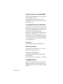
To configure Pro Tools for ProControl:
1 Open the ProControl page of the
Pro Tools Peripherals dialog.
• Macintosh: Use the Ethernet port pop-up
menu to select which Ethernet port you
want to connect to. Ports are identified
by (CPU) name.
• Windows NT: Use the Windows Network
Control Panel to change the binding (refer to your Windows NT documentation
for more information).
4 Use the Unit pop-up to select which ProControl unit is on-line at each position—
#1, #2 and so on. Placing a Main Unit between two Fader Packs, for example, lets
you keep the main work area in the “sweet
spot” of your mix environment. If you
have one Main Unit with a single Fader
Pack to its right, settings would be similar
to the following example.
2 Click enable. Pro Tools scans the Ether-
net connection for any ProControl units
connected to the system.
Configuration for main unit at far left, one fader pack
to the right.
You can designate any unit (Main or Fader
Pack) to be “1st” “2nd” “3rd” and so on using the Unit pop-ups.
ProControl page of the Pro Tools Peripherals dialog
3 If the CPU has multiple Ethernet ports
(built-in, a bridge or other add-on) do the
following:
If ProControl does not appear in the Peripherals > ProControl menus, check the
following:
• Ethernet port settings and connections.
• If in a networked ProControl/Pro Tools
installation, you might be connected to a
different zone or not bridged to the correct zone. Bridges must be configured as
routers.
Chapter 2: Installing ProControl 23
5 To rename a unit, see “Naming ProCon-
trol Units” on page 24. By default, units are
named either MAINUNIT or FADERPK.
6 Click OK to close the Peripherals dialog
and save your configuration settings.
7 Pro Tools may ask if you want to down-
load new firmware to update ProControl.
Pro Tools will always contain the most recent firmware, so you should probably
click to Download new firmware (see “ProControl Firmware” on page 24).
If communication is established (or, after
downloading new firmware), the appropriately colored outline colors for each unit
will appear around the current bank of
channel strips in Pro Tools Mix window.
If problems persist after power-cycling and
checking connections, refer to “Troubleshooting” on page 28.
Once ProControl units have been enabled,
choices are stored and you will not have to
re-open the Peripherals dialog again unless
changes to the configuration are necessary.
Display of Unit Status in the Peripherals
Window
ProControl Firmware
Each release of Pro Tools includes the most
current ProControl firmware. After enabling ProControl units in the Peripherals
dialog, Pro Tools compares the firmware of
all connected units to the version available
in the Pro Tools software. If a discrepancy is
found, Pro Tools will suggest that you
download new firmware to your units.
In networked environments, be careful not
to accidentally select remote (other) ProControl units. Also, firmware downloading
resets all ProControl preferences (UTILITY
settings) to their factory defaults, listed in
“Reset (Factory Default) Page” on page 202.
Naming ProControl Units
By default, Fader Packs are all named “FADERPK.” If, for example, the system includes
one Main Unit two Fader Packs, the pop-up
window will list MAINUNIT, FADERPK,
FADERPK. Naming units uniquely can
avoid confusion in networked systems also.
✽ You can rename ProControl units individu-
ally using Local Mode. See “Remote (Local)
UTILITY Mode” on page 193.
MAINUNIT or FADERPCK
Bold type indicates connected units.
MAIN UNIT or FADERPCK
Italics indicate lost/disconnected units.
MAINUNIT or FADERPCK
Underlined names indicates that the
selected units are in use by another
Pro Tools system.
24 ProControl Guide
To rename a unit from the Peripherals dialog:
■ Choose Setups > Peripherals and click
ProControl.
■ Click the Name Unit(s) button and enter
the unit name in the dialog that appears,
then OK the dialog (or cancel).
If there is any confusion about which unit
is which, OK the Peripherals dialog, move a
Pro Tools fader on-screen and check if ProControl faders follow.
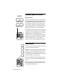
QuickStart System Test and
Configuration
It is assumed that you have completed the ProControl installation and setup instructions contained in this chapter.
✽ For a video guided tour of ProControl, use the ProControl Tu-
torial CD-ROM (included with your Main Unit).
To begin:
CONTROL ROOM
■
MIX TO
AUX
AUX (5-6)
Launch Pro Tools and open the Demo Session.
STEREO MIX
TRIM 5
To play the Demo Session
TRIM 6
SRC 1 (3-4)
TALKBACK
SRC 2 (5-6)
MONO
ALT (3-4)
ALT
SRC 3
CONTROL ROOM section using the Main (1-6) pot so that
the volume is relatively low to start.
2 Press PLAY on the ProControl Transport.
3 Adjust the main volume using the MAIN (1-6) knob.
DIM
MUTE
MAIN (1-6)
1 Adjust the monitor output level from the
HEADPHONE
As the demo plays, feel free to grab a fader and give it a
shove, or solo/mute some tracks and track groups.
4 To stop the Demo Session, press STOP (or press the Space
bar of your computer keyboard—both Pro Tools and ProControl switches and controls are “live” at all times, so you
can work from either environment).
If for some reason you weren’t able to play and hear the
Demo Session, you may have skipped a step in your installation or software configuration. To find the problem, refer
to the Troubleshooting section that follows.
Chapter 2: Installing ProControl 25
Setup and Configuration
Options
Audio Monitoring Defaults
ProControl provides the following monitoring modes and options, along with a description of their default (factory) settings:
Stereo, single-source input/monitoring In
this mode, one single stereo input source
(ProControl Main In, Source 1, 2 or 3 In)
can be monitored through ProControl at a
time. Also known as X-Or selection. (For
instructions on how to configure source
monitoring mode, see “Single Source (“XOR”) and Multiple Input Source Monitoring” on page 43).
Mute > Control Room Only This mode
causes only the Control Room Main and
Alt outputs to mute using the MUTE switch
in the Control Room section. The Aux outputs (intended for cue/headphones) do not
mute.
Internal Talkback (built-in TB mic) In this
mode, the built-in Talkback mic supplies
input to the ProControl talkback bus.
Basic Configuration Options
Stereo and Surround Monitoring
ProControl provides stereo and surround
monitoring modes. When patched correctly, up to six channels of Pro Tools audio can be monitored through six discrete
ProControl outputs, with stem (pair) level
and on/off control. (See “Using the Control
Room Monitoring Section” on page 41.)
26 ProControl Guide
To monitor in surround mode:
1 Press the UTILITY switch on your Main
Unit. The DSP EDIT/ASSIGN section
changes to display several choices, with illuminated red switches next to each.
SYSTEM
MONITOR
TEST
RESET
PREFS
<>
<>
ESCAPE
2 Press the switch next to MONITOR. Now,
monitor options are displayed.
3 Press the switch for MODE, which dis-
plays choices for Stereo and Surround.
4 To enable surround mode, press the
switch next to SURROUND. To switch back
to stereo mode, press the STEREO switch.
Fader Resistance
Fader pull back, or resistance, determines
the “feel” of fader travel. To optimize fader
response/feel, each ProControl unit has adjustable fader resistance to provide looser
or tighter fader response.
Fader resistance can be applied globally (to
all Main and Fader Pack units) from the
Main Unit. Fader Packs can also be adjusted
individually.
To adjust Fader Resistance:
Main Unit
1 Press UTILITY > PREFS > FADER.
2 Use the Scrub/Shuttle wheel to
raise/lower fader resistance. You can move
any faders on the main unit while adjusting the wheel to feel the change.
Fader Pack:
1 Press and hold SHIFT/ADD +
OPT(ALT)ALL + F4. The top row of data displays (above the pan knobs) display:
SYSTEM | TEST | PREFS
2 Press the flashing red switch to select
PREFS. From the next list of choices, select
FADER.
3 Rotate any data encoder (knob) to raise
or lower fader resistance. Check the effect
of various settings by moving a fader while
turning the encoder to adjust resistance.
be displaying and controlling pan of
channels 1-8, while a Fader Pack is simultaneously displaying and controlling
Send B level on channels 9-16.
By default, ProControl units operate in global SELECT/ASSIGN. You can switch between global and local at any time to
match the needs of your project.
To select local or global SELECT/ASSIGN:
■ Press and hold the OPT (ALT) ALL
switch, then press the FLIP switch.
The displays above the unit’s rotary encoders (pan knobs) will display:
SELECT | ASSIGN | Switches | Are | Now | In |
Local | Mode | < > |
Repeat the above step to return a unit to
global mode (the display will read “...Now
In Global Mode”).
Control Room Default Settings
Fader Pack Options
Local and Global SELECT/ASSIGN
control
In expanded ProControl systems, Fader
Packs can be configured to function in global or local SELECT/ASSIGN.
• In global mode, all connected ProControl units respond as one to channel-specific mode selections including pan,
input/output assignment, and channel
send assignment, send level and so on
(referred to as SELECT/ASSIGN settings).
• In local mode, each unit (Main or Fader
Pack) functions independently in regards
to these channel-specific parameters. For
example, local mode lets the Main Unit
There are additional set up options available for the Control Room Monitor features, including:
• Monitor Mode, including Stereo/Surround and Multi-/X-Or source monitoring))
• Mute/Dim
• Talkback/Listenback, including slate/dub
and rerecord
Instructions for these and all Control
Room options can be found in “Using the
Control Room Monitoring Section” on
page 41.
Chapter 2: Installing ProControl 27
Troubleshooting
Communication Problems
If communication is ever lost, Pro Tools
posts a dialog explaining that this has occurred and suggests that you check connections or power-cycle the units. ProControl
automatically attempts to recover communication until it is reestablished or you cancel the warning dialogs.
Modal Dialog Messages
Before you begin working with ProControl,
you should become familiar with some
modal dialog messages which may appear:
Pro Tools On-screen Dialog Warning
If a modal dialog message appears in
Pro Tools, ProControl will display the following message in the DSP EDIT/ASSIGN
section displays:
Pro Tools
Pro Tools “Lost Communication” Message
has a
If Pro Tools loses communication with ProControl because power or a cable connection has been cut off, for example, the
main unit will display “OFFLINE” in the
Time Counter Display. A message will appear on-screen in Pro Tools.
dialog
If this happens, power down ProControl,
wait a few seconds, and then power up ProControl again. If communication problems
persist, make sure cable connections are
properly configured and secured.
If ProControl is not in use, disable it in
Pro Tools Peripherals dialog.
Lost unit names are listed in italics and networked units are underlined in the Peripherals dialog. (Disable ProControl in the Peripherals dialog, to make it available to
other networked systems.)
If communication does not resume, or if error messages continue to appear, click Enable (in the Peripherals window).
Once ProControl units have been enabled,
you do not have to re-configure the Peripheral Dialog again unless changes to the
setup are necessary.
28 ProControl Guide
on
screen!
This message will continue to be displayed
until the dialog is closed on-screen in
Pro Tools or by using ProControl (press ENTER or ESCAPE).
Active in Background Message
If Pro Tools displays the following message:
“ProControl is currently inactive because
Active in Background is disabled in
Pro Tools”
Choose Operations > Active in Background to restore communication.
■
Resetting and Calibrating
ProControl provides numerous self-diagnostic tests, recalibration routines and customizable parameters. These options are in
the Utility pages, described in the Appendix of this guide.
chapter 3
ProControl Basics
This chapter takes you on a guided tour
through each section of the ProControl
surface, and includes sections dedicated to
the Transport and Control Room Monitoring features.
Some ProControl Terms
bank A group of controls that are the same
and that are arranged in discrete channel
strips. ProControl Main Units consist of
banks of eight faders. An expanded system
with one Main and one Fader Pack (two total ProControl units) would comprise
banks of 16 faders.
global controls Controls that affect all Main
and Fader Pack Expansion units in a system. “Local” controls only affect the unit
on which they are invoked.
data encoders Rotary data encoders are virtual knobs, with LED ring lights that represent values for parameters such as pan position and send level.
dedicated controls These controls perform
single functions that never change. These
controls are not “banked” or “paged”. For
example, the transport switches and the
jog/shuttle wheel never change their function.
bank selecting The process of switching
from one bank of channel strip faders to
another. For example, on-screen channel
strips 1-8 will be bank #1, channel strips 916 will be bank #2, and so on. (Expanded
systems bank 16, 24, or 32 channels at a
time.) This is also called bank swapping.
Chapter 3: ProControl Basics 29
Meter section
• Eight LED meters for Input/Channel/Track level indication
• Time Counter Display
• Six LED meters for master output level
The Fader Section
Channel SELECT/ASSIGN section
• Twelve SELECT/ASSIGN switches to select data encoder function
• Pan, send level, input and output, and Flip mode controls
Channel AUTOMATION section
• Eight automation MODE switches
• Eight automation ENABLE switches
• AUTO SUSPEND switch
KEYBOARD SHORTCUTS section
• Computer key command equivalent switches
Faders and channel controls
• Eight 100 mm., touch-sensitive DigiFaders™ for channel volume or send level
• Eight single-row 8-segment LED displays for channel name and headroom display
• DISPLAY MODE switch to toggle name, group, dB values and channel numbers
• Eight data encoders with 15-LED indicator rings for pan, send and I/O control
• Eight single-row 8-segment LED dot-style displays for encoder data display
• Eight SOLO, MUTE and SELECT switches
• Eight ASSIGN/MUTE switches for sends and I/O, and for selecting pre/post for sends
• Eight REC/RDY record-arming switches
• Eight dedicated EQ and DYN IN/EDIT switches
• Eight INS/SEND select switches
• Eight AUTO Mode switches LED labels
• INS/BYP switch for INS/SEND switch row
• AUTO SUSPEND switch to suspend automation playback
• Master SOLO clear and indicator switch
• Four Master Function Switches and four “F-key” function switches
30 ProControl Guide
Time Counter Display
• LED time counter display for viewing current session time
• COUNTER MODE switch toggles SMPTE, Min/Sec, Feet/Frames
The Main Section
DSP EDIT/ASSIGN section
• Eight data encoders for Plug-In/Insert parameters
• Eight LED displays for Plug-In parameters
• 24 insert assignment and editing switches
• INSERTS/PARAM switch for Plug-In editing
• MASTER (Plug-In) BYPASS switch
• COMPARE switch (Plug-Ins)
• LED display for CHANNEL/GROUP
CONTROL ROOM analog monitoring section
• Three stereo OUTPUT level controls
• TALKBACK level control
• Built-in TALKBACK microphone
• HEADPHONE level control (for front-panel headphone jack)
• Four MONITOR SELECT switches (input source)
• ALT speaker select switch
• Switches for MUTE, DIM, and MONO monitoring
• Two TRIM pots for use in a surround monitoring configuration
• Slate/Dub capability
Numeric Keypad
Trackpad
Main Section
• TRANSPORT controls, AUDITION switches
• SCRUB/SHUTTLE wheel with 2 mode switches
• TALKBACK switch
• Fourteen dedicated Pro Tools EDIT switches, SAVE and UNDO switches
• Dedicated WINDOW switches to select active Pro Tools window
• Seven Global STATUS select switches
• Five GROUP switches
• MASTER FADERS switch
• Two BANK SELECT switches, with NUDGE function switch
• ZOOM/SELECT switches, w/ one cursor quadrant-mode switch
• CHANNEL MATRIX for status, navigation, group functions, Plug-In paging
• Four BANK switches
• GO TO, VIEW, UTILITY and ALPHA mode switches for the CHANNEL MATRIX
• ESCAPE switch
Chapter 3: ProControl Basics 31
Transport Switches
Primary Transport Switches
The Transport switches correspond to transport functions
in Pro Tools. These switches are:
1
2
3
4
5
1 REWIND Rewinds through the session beginning from the
current cursor position.
2 FAST FORWARD Fast-forwards through the session beginning from the current cursor position.
0
-2
-4
-6
-8
-10
-14
-18
-22
-26
-30
-35
-40
-45
-50
1
2
3
4
5
3 STOP Stops playback.
6
1
2
3
4
SELECT / ASSIGN
GROUPS
5
4 PLAY Begins playback from the current Timeline or Edit
location.
6
7
8
DSP EDIT / ASSIGN
CHANNEL / GROUP
CHANNEL MATRIX
WINDOWS
AUTOMATION
STATUS
EDIT MODE
EDIT FUNCTION
NUDGE
BANK SELECT
EDIT TOOL
5 RECORD Arms Pro Tools for recording. Exact function is
determined by the current Pro Tools record mode (QuickPunch, Wait for Note, Pause).
SHORTCUTS
TALK
BACK
Control Section
ON
LINE
EXT
TRANS
LOOP
PLAYBACK
LOOP
REC
QUICK
PUNCH
Directly above the main transport buttons are seven additional transport function switches:
Online Toggles Pro Tools online/offline (LED is lit when
Pro Tools is online)
RTZ (Return-To-Zero) Sets playback cursor to the beginning
of the session
END (Go-To-End) Sets playback cursor to the end of the session
EXT TRANS (External Transport) Enables machine control
of a single external transport
LOOP PLAYBACK Toggles Loop Playback on/off (LED is lit
when Loop Playback is enabled)
LOOP RECORD Toggles Loop Record on/off (LED is lit when
Loop Record is enabled)
QUICKPUNCH Toggles QuickPunch recording mode state
(LED is lit when QuickPunch is enabled)
32 ProControl Guide
In addition to the above, there are several modifier shortcuts for transport function:
• CTL/CLUTCH + PLAY: engages Pro Tools Pause mode
• SHIFT/ADD + PLAY: initiates half-speed playback
• SHIFT/ADD + STOP: cancels the current record pass
• SHIFT/ADD + FAST FORWARD: Go-To-End
• SHIFT/ADD + REWIND: returns to zero (RTZ)
• CTL/CLUTCH + RECORD: cycles through the various
record modes (normal, QuickPunch, Loop)
• CTL/CLUTCH + EXT TRANS: cycles through available
machine master choices, (such as Pro Tools, Serial Machine, and ADAT).
• OPT (ALT) ALL + IN or OUT: centers the left or right side
of any current on-screen waveform selection in the Edit
Window.
AUDITION, PRE/POST, IN/OUT Switches
AUDITION
PRE
IN
OUT
POST
Directly above the seven special function Transport
switches (ONLINE, RTZ, etc.) are the ProControl audition
controls.
PRE, IN, OUT and POST function in two available modes:
• Standard mode (AUDITION switch is off): activate
pre/post roll (PRE and POST) and define in/out points
during playback (IN and OUT).
• Audition mode (AUDITION switch is lit) PRE, POST, IN
and OUT each “audition” a unique range of audio
in/around the current Edit selection (see “Example of
AUDITION Mode Playback Options” on page 34 for details).
Pre and Post-roll
To toggle Pre- or Post-roll on/off:
1 Make sure AUDITION is off.
2 Press PRE or POST to toggle each on or off.
Chapter 3: ProControl Basics 33
Setting Pre- and Post-Roll Amounts
To enter a Pre/Post-Roll Time:
1 Hold down c - (CTL) and then press PRE or POST. The ap-
propriate switch LEDs (PRE or POST) will flash, indicating
that PRE/POST entry mode is active.
2 Type values for PRE/POST using the numeric keypad.
Press the ProControl PREVIOUS or NEXT switches to tab
through the numeric fields.
3 Press ENTER to set the time values. Press ESCAPE to cancel
changes.
Defining in/out points
To define selection in and out points during playback:
1 Make sure AUDITION is off.
2 While Pro Tools is playing, press IN to define selection
start, then press OUT at the desired selection end.
AUDITION Mode and PRE, IN, OUT, POST
The AUDITION switch toggles Audition mode on and off.
When on/lit, playback can be controlled from the PRE, IN,
OUT and POST switches (detailed below) to quickly listen to
the either selection start or end, with or without pre- and
post-roll as described below.
Example of AUDITION Mode Playback Options
To understand what PRE, IN, OUT and POST let you do
while in Audition mode, let’s assume you currently have a
four bar selection spanning bars four through 8, with one
bar of pre-roll and one bar of post-roll already defined:
PRE Plays audio starting at the pre-roll point up to the beginning of the selection. In our 4 bar selection example, this
would play from bar 3 to bar 4.
IN Plays audio starting at the selection start through the
length of the post-roll amount. In our example, this would
play from bar 4 to bar 5.
34 ProControl Guide
OUT When in AUDITION mode the OUT button plays audio
back-timed from the selection end by the pre-roll amount.
In our example, this would play from bar 7 to bar 8.
POST Plays audio from the end of a selection by the postroll amount. In our example, this would play from bar 8 to
bar 9.
Additional ProControl Transport Shortcuts
To listen to the edit/selection start point with both pre and
post roll:
■
Hold down c (CTL) + OPT (ALT) ALL then press PRE or IN
To play edit/selection end with pre-and post-roll:
Hold down c (CTL) + OPT (ALT) ALL, then press OUT or
POST
■
Transport Mode for NUMERIC KEYPAD
For additional flexibility, the NUMERIC KEYPAD can be
configured for Transport command.
To engage Transport Mode for the Numeric Keypad:
1 In Pro Tools, choose Setups > Preferences, and click Oper-
ations.
2 Enable Transport mode.
3 Click OK.
Chapter 3: ProControl Basics 35
The following table lists NUMERIC KEYPAD functions
when Transport mode is enabled:
Task
NUMERIC KEYPAD
Play/Stop
0
Rewind
1
Fast Forward
2
Record (Punch In/Out)
3
Loop Play
4
Loop Record
5
QuickPunch
6
Metronome (MIDI)
on/off
7
Count on/off (MIDI)
8
Merge Record (MIDI) on/off
9
Enter Main Counter
Asterisk (*)
Enter/Edit Time Fields
Backslash (/)
Capture Time Code
=
Create Memory Location
Enter
Nudge fwd/bwd
+/-
For other modes/shortcuts, see the Pro Tools Reference Guide.
Commands Focus Transport Shortcuts
When the Pro Tools Commands Focus is engaged, several
transport commands become available from the Alpha keys
in the ProControl CHANNEL MATRIX.
To engage Commands focus:
Press c (CTL) + OPT (ALT) ALL + 0 (numeric zero). The
Commands toggle lights in Pro Tools Edit window.
■
For a listing of single-key Command shortcuts in Pro Tools,
see Appendix C: ProControl Shortcuts and Equivalents.
36 ProControl Guide
Transport Control of External Devices
Using the EXT TRANS switch, ProControl can toggle between Pro Tools or your external device as the transport
master or slave.
To toggle/select the Transport Master:
1 Hold down CTL/CLUTCH while you press the
EXT TRANS switch. This cycles through all currently available choices for machine transports:
Selecting the Transport master
As you change the transport master, the ProControl DSP
EDIT/ASSIGN display posts the message, “Transport now
controls ADAT” or “Transport now controls Serial Machine”
as relevant.
2 When the desired transport is selected, release the
CTL/CLUTCH switch to save the setting.
3 Now, pressing only the EXT TRANS switch toggles be-
tween the selected device and Pro Tools as the transport
master.
4 To select a different alternate device, use CTL/CLUTCH +
EXT TRANS again.
Display of EXT TRANS modes
Pause mode When Machine (serial) is transport master and
the remote system is in PAUSE mode, the ProControl PLAY
switch will blink and the STOP switch will light.
Cueing While the remote system is cueing, the ProControl
PLAY and SCRUB switches blink, and the STOP switch illuminates. (Scrub/Shuttle remain available for scrubbing, jogging or shuttling the deck. See the sections on SCRUB and
SHUTTLE later in this chapter for information.)
Chapter 3: ProControl Basics 37
Record The ProControl RECORD switch LED always tracks
the state of the device under control. Keep in mind, however, that this is distinct from the remote track-arming capabilities provided by the MachineControl option for
Pro Tools (available separately from your Digidesign
dealer).
Footswitch Control
There are two general-purpose footswitch inputs (for momentary footswitches) on the rear panel (SW1 and SW2)
that are used for general transport control. Either footswitch can control Play/Stop, Punch in/out, or Talkback. In
addition, the polarity of each switch can be reversed.
To configure the Footswitch (SW1, SW2) parameters:
■ On your Main Unit, press UTILITY>PREFS>SWITCH1 or
SWITCH2 (the options are the same for both). Now select
the Polarity (+ or -) and function for the selected switch
(PLAY/STOP, RECORD or TALKBACK).
When either footswitch is employed, the following shortcuts are available:
To cancel a record pass:
Hold down SHIFT/ADD and press Footswitch #1 to cancel
the recording without saving the most recent recording.
■
To initiate half-speed playback:
■
38 ProControl Guide
Hold down SHIFT/ADD and press Footswitch #1.
Level Meters
0
-2
-4
-6
-8
-10
-14
-18
-22
-26
-30
-35
-40
-45
-50
0
-2
-4
-6
-8
-10
-14
-18
-22
-26
-30
-35
-40
-45
-50
1
2
0
-2
-4
-6
-8
-10
-14
-18
-22
-26
-30
-35
-40
-45
-50
3
4
0
-2
-4
-6
-8
-10
-14
-18
-22
-26
-30
-35
-40
-45
-50
5
6
PRO CONTROL
Along the top of ProControl are eight stereo, 15-segment
LED meters for global pre- or post-fader level indication of
individual channels, as well as six more meters to the right
of the Time Counter display for master output levels. Mono
channels activate the left side of the meter pair only.
ProControl meters follow Pro Tools Peak Indication preferences, and are identical in operation to the meters on
Digidesign Audio Interfaces.
To clear all clipped meters and held peaks:
Press the CLR/F1 switch in the F-keys (Function keys) section to clear clipped channel and send meters and last held
peaks simultaneously, on all ProControl meters (except
Plug-Ins). This also clears all audio interface meters.
■
WINDOWS Switches
Six WINDOW switches open or close the corresponding
Pro Tools window.
• MIX and EDIT
• STATUS: Session Setup
• TRANS: Transport
• PLUG-IN:
• MEM-LOC: Memory Locations
About the TRANSPORT, MEM-LOC, STATUS and
PLUG IN STATUS Switches
Pressing these switches brings the selected window to the
foreground as the “active” floating window for editing. The
Transport, Memory Location, Session Setup Display and Inserts/Sends windows are all floating windows. If a floating
window is already in the foreground, then pressing its corresponding switch will close the window.
Chapter 3: ProControl Basics 39
Visibility of Inserts/Sends Editor
The PLUG-IN switch opens/closes the Inserts/Sends Editor
for the currently selected Plug-In). When a Plug-In is selected for editing on ProControl, the corresponding Inserts/Sends Editor for the Plug-In will also open in
Pro Tools. Only a single Plug-In can be accessed and edited
at a time. Note that if the Inserts/Sends Editor for the currently selected Plug-In is closed, you can still edit the PlugIn using the DSP EDIT/ASSIGN section even though the
Plug-In interface is hidden. This “edit focus” mode of operation allows for maximum editing speed on ProControl,
avoiding the need for Pro Tools to continually redraw the
Plug-In interface on-screen. For more information, see
Chapter 7: Plug-Ins and Sends.
Time Counter Display
HOURS
MINUTES
SECONDS
MS
HOURS
MINUTES
SECONDS
FRAMES
0.0. 09. 47. 05.
FEET
BARS
FRAMES
BEATS
TICKS
In the center of the meter section is an 8-character, 7-segment LED display for showing time values. Each numeric
section of a given time display is separated by LED dots.
This display will show whatever is displayed on the
Pro Tools main counter display, indicated by the labelled
LEDs next to each option:
HOURS MINUTES SECONDS MS
HOURS MINUTES SECONDS FRAMES
FEET FRAMES
BARS BEATS TICKS
The time display format can be selected from ProControl using the COUNTER MODE switch, located directly below the
Time Counter display.
COUNTER MODE Switch
The COUNTER MODE switch is located between the DSP
EDIT/ASSIGN section and the main Fader section, directly
below the Time Counter display. Repeatedly pressing this
switch toggles the LED time display through each of the
time display modes. A green LED next to the counter dis40 ProControl Guide
play shows which of the following modes is active. (Samples
is indicated by all green Time Counter Display LEDs off.)
Some time displays, such as Minutes/Seconds have a leastsignificant digit display in thousandths of a second (three
characters). These values are truncated or rounded to be displayed in the ProControl counter, and appear when playback is stopped (for example, “01:00:02:022” will display as
“01.00.02.02”).
For information on keyboard entry for the counter, see “The
Numeric Keypad” on page 52.
Using the Control Room Monitoring
Section
ProControl’s CONTROL ROOM Monitoring section provides high quality audio reproduction and routing for monitoring of the outputs of Pro Tools mixes and alternate
sources to speakers and headphones.
The analog CONTROL ROOM section provides multisource/destination monitoring, supporting three stereo
output level controls, four monitor select switches (i.e., input controls), an ALT speaker select switch, a built-in talkback mic with level control, headphone level control, and
monitor MUTE, DIM and MONO switching.
The CONTROL ROOM section retains all of its settings on
power-down and restores them on power-up without any
intervention from the host computer, and its circuits automatically mute during power down/up to prevent thumps
and other spurious signals that could damage speakers.
Two global monitoring modes are available: stereo and surround. Switching between these two master monitor modes
is accomplished from the ProControl UTILITY page. Many
other ProControl options are also available in the UTILITY
page, which is explained in Appendix A: UTILITY Settings. All
choices made in the UTILITY section (as well as some other
specialized functions) are stored in ProControl’s EEPROM
memory. These functions do not require a CPU to be conChapter 3: ProControl Basics 41
nected in order to be changed/accessed, nor do they require
Pro Tools software to be active.
Here is an overview of the two monitor modes:
STEREO Monitor Mode Overview
In stereo mode, the CONTROL ROOM section lets you
monitor in stereo, with the following features:
• Source switching between 4 stereo sound sources (STEREO MIX, SRC 1 (3-4), SRC 2 (5-6), and SRC 3).
• Speaker selection (main or ALT monitors)
• AUX I/O section for separate cue mix monitoring or alternate Source I/O
• DIM, MUTE, MONO, on monitor (speaker outputs)
• Talkback, Slate, and Listenback (“talent listen”)
• Analog source dubbing (from the re-record/Slate input
pair)
SURROUND Monitor Mode Overview
In surround monitor mode, the CONTROL ROOM section
allows you to utilize discrete surround mix sources for monitoring. Both 4 channel (standard Dolby® Digital) and 6channel modes (i.e., 5.1), are supported.
• 4-channel surround comprised of four signals: Left, Center, Right, and Surround (mono).
• 6-channel surround (5.1) comprised of six signals: Left,
Center, Right, Left Surround, Right Surround, and a Subwoofer (or LFE) channel.
SURROUND monitor mode also provides source muting (in
pairs), level trims, a master level control, and MONO and
DIM features.
While in surround mode, the individual source input selectors carry the discrete surround signals in pairs. The output
level controls are used to control each surround “stem” mix
in pairs, with master control from the MAIN (1-6) master
level control. Individual level trim is available for the Aux 5
and Aux 6 signal.
42 ProControl Guide
Single Source (“X-OR”) and Multiple Input Source
Monitoring
Input sources can be toggled between single source X-OR (default) and multiple source operation while in Stereo Monitor
mode. In Surround mode, multi-source/discrete routing is
always enabled. Here is how these two options affect the
way in which you can use the CONTROL ROOM section:
While in Stereo Monitor mode
◆ When single source (X-OR) is the current mode, only one
input source can be monitored at a time when working in
Stereo monitor mode. In this mode, only a single input
source selector switch can be active at a time (selecting a
new choice turns off the current choice). This means that,
for example, you will not be able to listen to the main
Pro Tools mix coming in on STEREO MIX simultaneously
with a DAT machine tape input coming in on SRC 1 (3-4).
◆ When multiple source is the current mode, any and all of
the four input sources may be monitored at one time while
in stereo monitor mode. Selecting more than one choice is
allowed, and with the example above, you would be able to
listen to both sources at once.
While in Surround Monitor mode
◆ When Surround mode is enabled, switch logic automatically changes to a special version of multiple source mode.
In this case, the input switches for each source turn the
“stem” on or off, but the outputs of ProControl’s monitor
section are discrete, not mixed. For example, you could enable/disable each input pair (main L/R, surround L/R (3-4),
and Center/Sub (5-6) with their associated switches (STEREO MIX, SRC 1, SRC 2, respectively). Then you can trim
the output levels for each stem pair using their master level
controls, and also trim the individual levels for Center (5)
and Sub (6) from the top-panel screwdriver-accessed trim
pots (explained below).
ProControl default (factory) configuration is Stereo/Single
mode.
Chapter 3: ProControl Basics 43
Selecting Monitor Mode Options
The following instructions for monitor mode selection use
UTILITY mode. In this mode, the DSP EDIT/ASSIGN
switches select utility options through a series of submenus
displayed vertically. Using the basic UTILITY instructions
listed below, you can quickly reset any monitor options by
following the instructions that immediately follow.
To enter UTILITY mode:
■
Press UTILITY.
The main UTILITY menu is displayed vertically in the DSP
EDIT/ASSIGN section LEDs.
MODE
MUTE/DIM
TALKBACK
LSTNBACK
<blank>
<blank>
<blank>
<ESCAPE>
When in UTILITY mode, the ASSIGN/ENABLE switches select menu choices that either take you to the next menu or
select an option.
Display of Current Settings
When making choices in the UTILITY section submenus, a
switch that is lit indicates that it is the currently enabled
choice. A switch that is flashing indicates that it is an available, but not the currently active choice.
44 ProControl Guide
Navigating in UTILITY Mode
To return to the previous UTILITY page at any time:
Press the flashing ASSIGN/ENABLE switch to the left of
the LED display that shows “ESCAPE.
■
To exit UTILITY entirely:
■ Press the flashing UTILITY switch in the CHANNEL MATRIX
Stereo and Surround mode
To select Stereo or Surround mode:
■ Press UTILITY > MODE > SURROUND, or STEREO as
needed.
Monitor Input Source Select Switches
CONTROL ROOM
MIX TO
AUX
AUX (5-6)
STEREO MIX
TRIM 5
This section comprises a set of 4 possible stereo monitor
sources for ProControl (in stereo mode), or as master stem
source enables for the matrix inputs (surround mode).
TRIM 6
SRC 1 (3-4)
TALKBACK
SRC 2 (5-6)
MONO
ALT (3-4)
ALT
SRC 3
DIM
MUTE
MAIN (1-6)
HEADPHONE
To engage an Input Source:
■ Press the switch in the CONTROL ROOM MONITORING
section that corresponds to the desired input source. If in
Single Source Monitoring mode, only one input source can
be engaged at a time. To be able to monitor more than one
SRC Input, ProControl must be in either Multiple Source
Stereo mode, or Surround mode.
See “Using the Control Room Monitoring Section” on
page 41 for instructions on enabling stereo or surround
mode.
Chapter 3: ProControl Basics 45
STEREO MIX Switch
This switch turns the STEREO MIX input pair on or off (Audio Input 2, channels 7 and 8). This input is +4 dBu and active-balanced.
◆ In stereo monitor mode, this switch turns the main
Pro Tools stereo mix on/off in the monitors.
◆ In surround monitor mode, this switch controls the
left/right (front) stem mix.
SRC 1, 2, 3 Inputs
Three switches labeled “SRC 1 (3-4)”, “SRC 2 (5-6)” and
“SRC 3” turn their respective rear-panel input pairs on or off
(Audio Input 2, channels 1-6). These inputs are +4 dBu and
active-balanced.
◆ In Stereo monitor mode—These stereo inputs would normally be connected to monitor any alternate 2 track source,
such as DAT machines or CD players.
◆ In Surround monitor mode—SRC 1 (3-4) receives the surround stem mix input source signals (Left/Right Surround,
Ls/Rs, or a mono surround channel). SRC 2 (5-6) receive the
center and subwoofer stem mix input source signals. SRC 3
is not utilized in Surround mode.
MIX TO AUX/AUX Input
CONTROL ROOM
MIX TO
AUX
AUX (5-6)
STEREO MIX
TRIM 5
TRIM 6
SRC 1 (3-4)
TALKBACK
SRC 2 (5-6)
MONO
ALT (3-4)
ALT
SRC 3
DIM
MUTE
MAIN (1-6)
46 ProControl Guide
HEADPHONE
When enabled in stereo monitor mode, the MIX TO AUX
switch (green LED) sends the current control room mix to
the AUX mix output pair (labeled Aux. Mix Output in the
wiring pin-out documentation). This mix could be any
combination of individual or mixed combination sources,
including STEREO MIX, SRC 1 (3-4), SRC 2 (5-6) or SRC 3).
This will depend on whether you are in Single or Multiple
Source Stereo mode or Surround mode (explained previously).
◆ In Stereo monitor mode—The MIX TO AUX switch routes
the current control room mix to the AUX mix output. The
feed to AUX In could be a Pro Tools output pair that is dedicated to the creation of a discrete, stereo cue (headphone)
mix. If MIX TO AUX is enabled (indicated by its green LED
lit solid), the talent will hear the same mix as the control
room. If MIX TO AUX f it is disabled (LED off), they will
hear their discrete mix (or whatever the source is).
◆ In Surround monitor mode—The MIX TO AUX switch is
inactive. This is because the surround matrix uses the AUX
MON level control as the level master for outputs 5 & 6 (the
center and sub channels, respectively. The AUX Input is
therefore inactive as well, and the input source for 5/6 is automatically connected to SRC 2 (5-6).
Control Room Monitor Level
Controls/Outputs
The CONTROL ROOM section’s level controls adjust the
volume of your outputs. Depending on whether you are in
Stereo or Surround mode, these dual-purpose controls do
the following:
MAIN (1-6)/Main Monitor Out
CONTROL ROOM
MIX TO
AUX
AUX (5-6)
STEREO MIX
TRIM 5
TRIM 6
SRC 1 (3-4)
TALKBACK
◆ In Stereo monitor mode, this rotary knob controls the
level of the main stereo control room output (Control
Room Main Out L/R). These L/R outputs would most likely
be connected to the main (stereo) speaker power amplifiers.
The control is inactive when in Single-source mode and the
ALT monitor switch is enabled (X-OR).
SRC 2 (5-6)
In Surround monitor mode, the MAIN (1-6) knob acts as
a level master for the entire surround matrix (outputs 1
through 6). In this mode, the control is effectively the
left/right surround output trim, and the overall master level
control for the surround matrix. All other mix stem elements are balanced against this “master level.” Other levels
within the Surround matrix are controlled by the other rotary knobs in the CONTROL ROOM section.
◆
MONO
ALT (3-4)
ALT
SRC 3
DIM
MUTE
MAIN (1-6)
HEADPHONE
ALT (3-4)/ALT Monitor Out
In Stereo monitor mode—The ALT (3-4)/ALT MONITOR
OUT knob controls the level for the Control Room ALT
monitor output. This output pair would most likely be connected to a power amp for smaller reference speakers.
◆
◆ In Surround monitor mode—This controls the output
level for the surround (Ls/Rs, or “satellite”) channels.
Chapter 3: ProControl Basics 47
AUX (5-6)/Aux. Monitor Out
CONTROL ROOM
MIX TO
AUX
AUX (5-6)
STEREO MIX
TRIM 5
This control acts as an output level control for the Aux output (in Stereo mode), or output 5-6 master trim (in Surround mode, acting in combination with top panel trims).
TRIM 6
SRC 1 (3-4)
TALKBACK
SRC 2 (5-6)
MONO
ALT (3-4)
ALT
SRC 3
DIM
MUTE
MAIN (1-6)
HEADPHONE
Stereo mode This control is a level control for the AUX Output pair. This output pair is intended to be used as a discrete
cue mix feed. It would typically be patched to a power amp
that would feed the artist cue (headphone) system, but
could be any stereo source. The input source for this feed
can be either the AUX In or the control room source mix
(STEREO MIX, SRC 1, etc.) when the MIS TO AUX switch is
engaged. You can use Pro Tools Sends to bus audio to a pair
(or a single, mono) of Pro Tools outputs, then connect
those outputs to the AUX IN (ProControl Audio Input port
1, channels 7 & 8).
Surround mode AUX (5-6) knob acts as an output level master trim for the center (5) and subwoofer (6) surround mix
stems simultaneously. For individual balancing of center (5)
and subwoofer (6) levels, use the top-panel screwdriver level
trims (“TRIM 5” and “TRIM 6) as described below:
Trim 5 & 6 - Level Trims
CONTROL ROOM
MIX TO
AUX
AUX (5-6)
STEREO MIX
TRIM 5
TRIM 6
SRC 1 (3-4)
TALKBACK
These are screwdriver-type top-panel accessible level trims,
located below and to the right of the AUX (5-6) level control. They trim the center and subwoofer stem mix output
levels individually against the AUX (5-6) control, which
acts as a master. They are attenuators only.
SRC 2 (5-6)
MONO
ALT (3-4)
SRC 3
To calibrate the Center and Subwoofer channels (Surround
mode only):
1 Engage the SRC 2 (5-6) Input Selector switch.
ALT
DIM
2 Set the AUX MON (5/6) control to maximum.
MUTE
MAIN (1-6)
HEADPHONE
3 While listening to surround material, use a screwdriver to
attenuate whichever Trim (center (5) or subwoofer (6))
needs adjustment. The trims are set at the factory for maximum output.
48 ProControl Guide
MUTE, DIM and MONO Controls
CONTROL ROOM
MIX TO
AUX
AUX (5-6)
Control Room MUTE Switch
STEREO MIX
TRIM 5
TRIM 6
SRC 1 (3-4)
TALKBACK
SRC 2 (5-6)
MONO
ALT (3-4)
The MUTE switch acts as a control room master mute, allowing speaker feeds to be muted. The MUTE switch does
not affect the Headphone signal (front-panel 1/4” connector). The current monitoring mode determines the available
MUTE options:
SRC 3
Stereo Mode
ALT
DIM
MUTE
MAIN (1-6)
HEADPHONE
Two modes of Control Room Mute are available: MUTE CR
(default) and MUTE ALL: These two different modes are selectable from the UTILITY/MONITOR page.
MUTE CR (Control Room) Mutes the MAIN and ALT output
pairs only. The AUX Out mix will not be affected. This is
useful when you want to have the control room speakers
muted, but you do NOT want to mute the talent mix feed
(either MIX TO AUX or AUX IN). This is the factory default.
MUTE ALL Mutes all of the audio output pairs (MAIN, ALT,
AUX). In this case, you would probably be using the AUX
out for some purpose other than a talent mix.
The MUTE modes can be selected from the ProControl
UTILITY page (UTILITY > MONITOR > MUTE/DIM).
Surround Mode MUTE silences all outputs at all times
(MAIN, ALT, AUX). In other words, all six outputs of a surround matrix are affected.
Refer to Appendix A: UTILITY Settings for instructions on
configuring ProControl UTILITY parameters.
Control Room MONO Switch
The MONO switch (green LED) mono-sums the control
room mix, allowing mono confidence monitoring. Listening to a mix in this manner lets you check phase and balance relationships of a mix in mono.
The switch is active in both Stereo and Surround monitor
modes, and affects the headphone output as well. It does
not affect Slate/Dub or the Aux output.
Chapter 3: ProControl Basics 49
Stereo mode Pressing MONO will mono-sum signals to the
MAIN output as well as the (front-panel) headphone output.
Surround mode Only the STEREO MIX outs are affected by
MONO. To confidence mix surround stems in Mono, simply press the MONO switch and then select each stem, one
pair at a time with the STEREO MIX (front left/right), SRC 1
(surround left/right) and SRC 2 (center, sub) switches.
Control Room DIM Switch
The DIM switch (yellow LED) inserts a 15 dB reduction in
level to the control room outputs. Depending on the chosen monitoring mode, most or all of the outputs will be affected by DIM as follows:
Stereo mode DIM affects MAIN (1-6) and ALT (3-4) outputs
only.
Surround mode DIM affects all outputs at all times (MAIN,
ALT, AUX). All six outputs of a surround matrix are affected.
The DIM switch does not affect the AUX (5-6) output (use
the AUX (5-6) rotary knob to lower this output level). It also
does not affect the front-panel headphone feed or
Slate/Dub feed. Press the DIM switch again to return to normal monitoring levels. The DIM switch LED extinguishes.
CONTROL ROOM
MIX TO
AUX
AUX (5-6)
STEREO MIX
TRIM 5
Control Room ALT Switch
TRIM 6
SRC 1 (3-4)
TALKBACK
SRC 2 (5-6)
MONO
ALT (3-4)
ALT
SRC 3
DIM
MUTE
MAIN (1-6)
50 ProControl Guide
HEADPHONE
In stereo mode, when enabled, the ALT switch (green LED)
routes the control room monitor mix to ALT Monitor Out.
This will usually be connected to an alternate set of monitoring speakers. Pressing the ALT switch disables the feed to
Main Monitor Out. In surround mode, this switch is inactive. ALT state is remembered when switching between surround and stereo monitor modes, and when powered
down.
Headphone
CONTROL ROOM
MIX TO
AUX
AUX (5-6)
STEREO MIX
TRIM 5
TRIM 6
SRC 1 (3-4)
TALKBACK
SRC 2 (5-6)
SRC 3
MONO
ALT (3-4)
A 1/4” stereo headphone jack is provided on the ProControl
front-panel (just below the Trackpad) for engineering confidence monitoring. It monitors the currently active main
control room audio at all times. The HEADPHONE level
knob in the ProControl CONTROL ROOM monitoring section adjusts the level of the headphones. The headphone is
not affected by the MUTE and DIM switches, but it is affected by the MONO monitor switch.
Talkback
ALT
DIM
MUTE
MAIN (1-6)
HEADPHONE
ProControl provides Talkback/Listenback capabilities that
include the TALKBACK level control, internal or external
Talkback/Listenback, Slate/Dub and rerecord features.
These are explained in Chapter 5: Recording.
UNDO and SAVE Switches
UNDO
SAVE
The UNDO and SAVE switches perform Undo and Save
functions corresponding to operations on the Macintosh.
The UNDO switch allows Undo/Redo of the last edit operation. The UNDO switch LED will be lit when the Undo function is available for use after an operation, and remain unlit
when there is nothing to “undo.” The UNDO switch LED
will flash when the Redo function is available.
The SAVE switch LED will be lit if the session has changed
from its currently saved state.
To save the changes in a session:
1 Press the SAVE switch. The SAVE switch LED will flash
when first pressed, indicating the Save process has been
armed.
2 If you wish to abort the Save process at this point, press
the ESCAPE switch.
3 If you wish to complete the Save process, press the SAVE
switch again. The SAVE switch LED will remain lit during
completion of the Save process, and then afterwards will
turn off.
Chapter 3: ProControl Basics 51
The Numeric Keypad
The Numeric Keypad, located to the right of the WINDOWS
selection switches, mimics keypad operation in Pro Tools
and is used for memory location store/recall, data entry of
counter values or numerics, for completing an editing operation (using the ENTER key), as well as for Pro Tools Transport and Shuttle modes. The functionality is identical to
that of your computer’s keypad, including modifier-key
shortcuts. Throughout this guide, there are instructions for
using the Numeric Keypad for all of its various functions.
The TRACKPAD
The trackpad functions just like the type found on high
quality laptop/portable computers, with two switches below it for clicking. You can also click, double-click, tripleclick and click/drag from the Trackpad directly, without using the Trackpad “click” switches.
Use the Trackpad to perform virtually every Pro Tools command, function or task directly from ProControl.
Configuring TrackPad Response
The Trackpad response follows the Mouse speed setting of
the host CPU.
To adjust the Trackpad:
1 Press UTILITY > PREFERENCES > MOUSE > MODE >
SPEED.
2 Select a response speed from Very Fast to Very Slow.
3 Press UTILITY to return to the previous ProControl mode.
✽ Additional control can be provided by the CPU mouse control
panel settings.
If the trackpad does not seem to be responding, ProControl
might be configured for External Mouse input. See “Mouse
Page” on page 201 for instructions.
52 ProControl Guide
Bank Switching and Channel
Scroll/NUDGE
NUDGE
BANK SELECT
0
-2
-4
-6
-8
-10
-14
-18
-22
-26
-30
-35
-40
-45
-50
1
2
3
4
5
6
1
2
3
4
SELECT / ASSIGN
GROUPS
5
6
7
8
DSP EDIT / ASSIGN
CHANNEL / GROUP
CHANNEL MATRIX
WINDOWS
AUTOMATION
STATUS
EDIT MODE
EDIT TOOL
SHORTCUTS
TALK
BACK
EDIT FUNCTION
NUDGE
BANK SELECT
Beneath the ProControl numeric keypad are the BANK SELECT switches. These include two bank switches with
left/right arrow symbols, and the NUDGE switch. Together,
these switches allow “bank swapping” or scrolling in single
channel increments. The BANK SELECT arrow keys switches
banks left or right eight channels or more at a time. For example, a basic system consisting of just a single ProControl
Main unit, which contains eight faders, will bank swap in
groups of eight channels at a time. An expanded system
comprised of one Main unit and three Fader Pack expansion
units (i.e., a 32-fader setup) would bank swap 32 faders at a
time. The NUDGE switch engages channel-scroll mode, in
which the BANK SELECT arrows scroll by one channel at a
time in the appropriate direction.
Mix/Edit Window Follows Bank Selection
Preferences
Bank-swapping and channel-scrolling behavior can be mirrored in Pro Tools. By enabling Mix Window Follows Bank
Selection or Edit Window Follows Bank Selection (in the
Display Preferences dialog), Pro Tools channel strips will be
banked into view automatically in response to ProControl
bank display. Color outlines appear around the channels
under the control of each ProControl unit. In some cases,
leaving these preferences off can improve bank swapping
speed (as Pro Tools does not have to redraw each bank).
Far-right/far-left Bank Select Shortcut
Holding down the OPT (ALT) ALL switch, press the appropriate BANK SELECT arrow switch to bank swap to the farleft or far-right bank position for the session.
■
Far-right bank-swapping will not “justify right.” For example, if you have a session that contains 22 channel strips,
holding down OPTION/ALL and pressing the right BANK
switch swaps to a bank consisting of only the five channel
strips #17-22.
Chapter 3: ProControl Basics 53
✽ The CHANNEL MATRIX’ GO TO and VIEW modes provide addi-
tional bank/channel navigation controls. Instructions for these
features begin in “GO TO” on page 69
Groups, Master Faders and BANK SELECT
In addition to bank/channel scrolling, the BANK SELECT
switches also let you move between vertical lists of eight
group members at a time (when Groups are being displayed
in the DSP EDIT/ASSIGN displays.) or Master Faders when
the MASTER FADERS switch is engaged. If there are more
than eight group members or master faders available to edit,
the Nudge switch will flash. (Groups and Master Faders are
described further in Chapter 4: Working with Tracks.)
ZOOM/SEL Switches
UP
PREVIOUS
NEXT
ZOOM / SEL
DOWN
In addition, the ZOOM/SEL cursor quadrant can be used to
navigate among fields/characters when entering alpha numeric values from the Numeric Keypad. For details on these
modes, see Chapter 6: Editing.
0
-2
-4
-6
-8
-10
-14
-18
-22
-26
-30
-35
-40
-45
-50
1
2
3
4
5
6
1
2
3
4
SELECT / ASSIGN
GROUPS
5
6
7
8
DSP EDIT / ASSIGN
CHANNEL / GROUP
CHANNEL MATRIX
WINDOWS
AUTOMATION
STATUS
EDIT MODE
EDIT TOOL
SHORTCUTS
TALK
BACK
54 ProControl Guide
EDIT FUNCTION
The ZOOM/SEL switches provide the same functionality as
the arrow keys on the computer keyboard (plus some additional features unavailable from the computer keyboard,
described soon). The ZOOM/SEL button in the center selects one of three modes for the UP, DOWN, NEXT and PREVIOUS switches:
• navigation,
• zoom, or
• select mode.
NUDGE
BANK SELECT
To select a ZOOM/SEL mode:
By default, ZOOM/SEL is in Navigation mode, and the
ZOOM/SEL switch is unlit.
■
To engage Zoom mode, press ZOOM/SEL until it flashes.
Use the Arrow keys to zoom in/out.
■
To engage Select mode, press ZOOM/SEL until it is lit
solid.
■
See “Navigating, Zooming and Selecting with ZOOM/SEL”
on page 121.
Zooming to “Entire Session” view and “Previous
View”
You can use the ZOOM/SEL switch to quickly zoom to “Entire Session” and “Previous View”.
To quickly zoom out so that the entire session is in view in
Pro Tools Edit Window:
■ Hold down OPT (ALT) ALL switch and double-press the
ZOOM/SEL switch.
To return to the previous zoom view:
■ Hold down OPT (ALT) ALL and press the ZOOM/SEL
switch.
Using the ZOOM/SEL Switches for Alpha Numeric
Entry
The cursor quadrant keys are also used when in ALPHA entry mode to navigate through fields/characters. ALPHA
mode is explained in “The CHANNEL MATRIX” on page 64.
Pressing the Right (NEXT) switch moves the text entry
point one character to the right.
■
Pressing the Left (PREVIOUS) switch moves the text entry
point one character to the left.
■
Additional ZOOM/SEL functions are explained in “Navigating, Zooming and Selecting with ZOOM/SEL” on page 121.
Chapter 3: ProControl Basics 55
KEYBOARD SHORTCUTS Section
SHORTCUTS
Modifier Key Switches
SHIFT / ADD
OPT (ALT) ALL
CTL / CLUTCH
z (CTL)
The Modifier key switches can also be used in any combination with keys on the computer keyboard to perform menu
command selection. The alphanumeric keys of the CHANNEL MATRIX can be used for this same purpose.
0
-2
-4
-6
-8
-10
-14
-18
-22
-26
-30
-35
-40
-45
-50
1
2
3
4
5
6
1
2
3
4
SELECT / ASSIGN
There are four switches that correspond to the various modifier keys on Windows and Macintosh systems. These are labeled SHIFT/ADD, OPT (ALT) ALL, CTL/CLUTCH and c (CTL). Using these modifiers with other switches changes
the action of those switches. For example, pressing and
holding down the OPT (ALT) ALL switch while pressing the
SOLO or MUTE switch will solo or mute all channels.
GROUPS
5
6
7
8
In ALPHA mode, the CHANNEL MATRIX (and NUMERIC
KEYPAD) also supports many of the single-key Command
shortcuts available with Pro Tools 5.0 (or higher). See
Appendix C: ProControl Shortcuts and Equivalents for details.
DSP EDIT / ASSIGN
CHANNEL / GROUP
CHANNEL MATRIX
WINDOWS
AUTOMATION
STATUS
EDIT MODE
NUDGE
EDIT FUNCTION
BANK SELECT
EDIT TOOL
SHORTCUTS
TALK
BACK
F-Key Switches
CLR / F1
At the top left of the Fader Section are four “F-Keys” (Function switches). Current assignments are:
F2
CLR/F1 Clears clips and last peaks held on the meter bridge,
on Pro Tools on-screen meters and Audio Interface meters.
F3
F2 Temporarily shows all channels that have Plug-Ins assigned by lighting the channel INS/SEND switches. Releasing
the F2 switch returns to the previous state.
F4
0
-2
-4
-6
-8
-10
-14
-18
-22
-26
-30
-35
-40
-45
-50
1
2
3
4
5
6
1
2
3
F3 (ProControl main unit only) Toggles between “Fixed”
and “Velocity sensitive” modes for the DSP EDIT/ASSIGN
encoders.
4
SELECT / ASSIGN
GROUPS
5
6
7
8
DSP EDIT / ASSIGN
CHANNEL / GROUP
CHANNEL MATRIX
WINDOWS
AUTOMATION
STATUS
EDIT MODE
EDIT TOOL
SHORTCUTS
TALK
BACK
56 ProControl Guide
EDIT FUNCTION
NUDGE
BANK SELECT
F4 (ProControl main unit only) Temporarily displays the
ProControl main unit’s Controller personality file version
in the DSP EDIT/ASSIGN displays.
SCRUB/SHUTTLE Wheel
The SCRUB/SHUTTLE wheel is used for Scrubbing, Shuttling, making selections/regions, and other edit operations.
The two switches directly above the wheel, labeled SCRUB
and SHUTTLE, choose the mode of operation. The
Scrub/Shuttle wheel can also control external devices such
as a serial machine (see the previous section Transport Control of External Devices for basic EXT TRANS set up).
Using SCRUB Mode
To use SCRUB mode:
1 While Pro Tools is stopped, press the SCRUB button. The
SCRUB switch’s LED will light and a message will be posted
vertically on the DSP EDIT/ASSIGN LED displays:
SCRUB
Mode
Enabled
Press
SCRUB or
STOP to
Exit
2 Aim Scrub at the selection start or end by pressing PREVIOUS (for start) or NEXT (for end).
3 Rotate the SCRUB wheel clockwise to scrub audio for-
ward, or counter-clockwise to scrub backward.
■ The scrub start position will be the location of the Edit
cursor when a waveform selection exists, or the location of
the Playback cursor location if there is no current selection.
■ The distance that the Scrub wheel travels determines the
length of the audio scrubbed, and wheel speed determines
Scrub speed. During Scrub mode, the REW and FFW LEDs illuminate (mirroring Pro Tools on-screen Transport).
Chapter 3: ProControl Basics 57
To SCRUB starting from the Selection End:
To begin scrubbing from the selection end position, press
and hold down the OPT (ALT) ALL switch before entering
SCRUB mode.
■
To SCRUB with “finer fixed” resolution:
Press and hold the c -CTL switch while scrubbing to engage fine-resolution scrubbing.
■
To exit SCRUB mode:
■ To exit scrub completely and return to normal operation,
press the SCRUB switch or any of the Transport switches. Alternatively, scrub may be exited by pressing the space bar on
the Mac keyboard, typing c (CTL) + “.” (period) on ProControl (or c + “.” on the Macintosh keyboard), or by pressing
the ESCAPE switch. You can also exit SCRUB mode by
switching to SHUTTLE mode.
58 ProControl Guide
Using SHUTTLE Mode
To use shuttle:
1 While Pro Tools is in stop mode, press the SHUTTLE but-
ton. The shuttle button LED will light and the following
message will be posted vertically on the DSP EDIT/ASSIGN
LED displays:
SHUTTLE
Mode
Enabled
Press
SHUTTLE or
STOP to
To Exit
<blank>
2 Rotate the SHUTTLE wheel clockwise to shuttle audio forward, or counter-clockwise to shuttle backward. The REW
and FFW switch LEDs will light (mirroring Pro Tools onscreen Transport switches). The SHUTTLE start position will
be the location of the Edit cursor when a waveform selection exists, or the location of the Playback cursor location if
there is no current selection.
Using the numeric keypad for SHUTTLE “lock” mode:
While in Shuttle Lock mode, you can use the NUMERIC
KEYPAD to control shuttle speed (with “0” being off, +9 being the fastest forward shuttle and -9 being the fastest reverse shuttle speed). The +/- keys are used to control shuttle
lock direction of play.
To exit SHUTTLE mode:
■ Press the SHUTTLE switch or any of the Transport
switches.
You can also exit SHUTTLE mode by pressing the Spacebar
on the computer keyboard, pressing ESCAPE on ProControl, or pressing c - (CTL) + “.” (period).
Chapter 3: ProControl Basics 59
About Scrub/Shuttle “Lock Out” Behavior
When scrub or shuttle is engaged almost all other controls
are “locked out.” Only the following ProControl/Pro Tools
controls will be available for use:
◆
SCRUB/SHUTTLE wheel and switches
◆ Any TRANSPORT switch (disengages scrub/shuttle and reverts ProControl to normal transport modes)
◆
Modifier switches
◆
Channel faders; MUTE and SOLO switches
Selecting Regions with Scrub/Shuttle
Scrub and Shuttle can be used to create selections/define regions in Pro Tools Edit Window. See Chapter 6: Editing for
more information.
Pro Tools Shuttle Mode Shortcuts
To engage Shuttle Mode for the NUMERIC KEYPAD:
1 Choose Setups > Preferences and click Operations.
2 Enable the Shuttle mode Numeric Keypad option.
60 ProControl Guide
When Shuttle is the selected Numeric Keypad shortcuts
mode, the following tasks may be initiated from the keypad
on ProControl:
Task
NUMERIC KEYPAD
1x Forward
6
1x Reverse
4
4x Forward
9
4x Reverse
7
1/4x Forward
3
1/4 x Reverse
1
1/2 x Forward
5-6
1/2x Reverse
5-4
2x Forward
8-9
2x Backwards
8-7
1/16x Forwards
2-3‘
1/16x Backwards
2-1
Loop Play Edit Selection
0
Enter Main Counter
asterisk (*)
Enter/Edit Time Fields
backslash (/)
Capture TimeCode
=
Create Memory Location
ENTER
Nudge later by grid
+
Nudge earlier by grid
-
Chapter 3: ProControl Basics 61
EDIT MODE, EDIT TOOL and EDIT
FUNCTION Switches
EDIT MODE
SHUFFLE
SPOT
SLIP
GRID
EDIT TOOL
TRIM
SELECT
GRAB
PENCIL
0
-2
-4
-6
-8
-10
-14
-18
-22
-26
-30
-35
-40
-45
-50
1
2
3
4
5
6
1
2
3
4
SELECT / ASSIGN
GROUPS
5
6
7
8
DSP EDIT / ASSIGN
CHANNEL / GROUP
CHANNEL MATRIX
WINDOWS
AUTOMATION
STATUS
EDIT MODE
NUDGE
EDIT FUNCTION
BANK SELECT
EDIT TOOL
SHORTCUTS
TALK
BACK
EDIT FUNCTION
CUT
COPY
PASTE
DELETE
SEPARATE
CAPTURE
The EDIT MODE and EDIT TOOL switches access the primary Edit function modes and tools:
• EDIT MODE – SHUFFLE, SLIP, SPOT, GRID. Pressing
one of these switches selects one of the four edit modes:
Shuffle, Slip, Spot, or Grid mode
• EDIT TOOL – TRIM, SELECT, GRAB, PENCIL. Pressing
one of these switches selects one of the main edit tools:
Trim, Select, Grabber, and Pencil (available when
zoomed in at very close resolutions only).
• To access the Smart Tool, press any two of the following
switches: TRIM, SELECT or GRAB simultaneously.
• EDIT FUNCTION - CUT, COPY, PASTE, DELETE, SEPARATE, CAPTURE. Pressing one of these switches selects
the corresponding Edit function.
These switches mimic their counterparts in Pro Tools. These
editing functions are explained in Chapter 6: Editing.
ESCAPE
The Escape Switch
0
-2
-4
-6
-8
-10
-14
-18
-22
-26
-30
-35
-40
-45
-50
1
2
3
4
5
6
1
2
3
4
SELECT / ASSIGN
GROUPS
5
6
7
8
DSP EDIT / ASSIGN
CHANNEL / GROUP
CHANNEL MATRIX
WINDOWS
AUTOMATION
STATUS
EDIT MODE
EDIT TOOL
SHORTCUTS
TALK
BACK
62 ProControl Guide
EDIT FUNCTION
NUDGE
BANK SELECT
The ESCAPE switch (green LED) is located at the bottom
right hand corner of the CHANNEL MATRIX area and is
used to confirm or cancel operations/settings. When an action has occurred that can be canceled by the ESCAPE
switch, the switch LED will flash.
The Master Faders Switch
The MASTER FADERS switch allows mono or stereo Master
Faders created in Pro Tools to be immediately displayed on
the Fader Section of the ProControl Main unit. Using this
switch, all Master Faders in the current session are instantly
called up on the ProControl Main Unit. This feature is especially useful in large sessions where it might be time consuming to Bank/Channel swap to the Master Faders.
To access Master Faders from the MASTER FADERS Switch:
1 Press the MASTER FADERS switch. Its LED flashes. All
MASTER FADERS
Master Faders that exist in the current Pro Tools session are
now displayed (right justified) in the Fader section of the
ProControl Main Unit. This is true even if you are using an
expanded ProControl system. In addition, all Pro Tools
Master Faders are displayed regardless of their current
Show/Hide status in Pro Tools.
2 Once these faders are up on the Fader Section, they may
be named, adjusted and automated in the same way channel faders are manipulated. If there are more than eight
Master Faders in the session, pressing the right or left BANK
SELECT button brings up the next set of Master Faders and
displays them on the ProControl Main Unit Fader Section.
3 To exit the MASTER FADERS mode, press the MASTER
FADERS switch again. This will return the ProControl Main
Unit Fader Section settings to their previous state/channel
display.
Chapter 3: ProControl Basics 63
DSP EDIT/ASSIGN Section
The DSP EDIT/ASSIGN section is at the top left of the Main
section.
In the DSP EDIT/ASSIGN section, you can assign, view and
edit Plug-Ins and Send/Insert parameters using the following controls and displays:
1 - Eight rotary data encoders (arranged vertically)
2 - Eight 8 segment LED displays for levels, names, etc., to
the left of each encoder
3 - SELECT/AUTO / PRE/POST switch column
4 - ASSIGN/ENABLE switch column
5 - BYPASS/IN/OUT/Ø and MUTE switches, to the right of
each encoder
0
-2
-4
-6
-8
-10
-14
-18
-22
-26
-30
-35
-40
-45
-50
1
2
3
4
5
6
1
2
3
6 -The INFO, INSERTS/PARAM and SENDS switches
4
SELECT / ASSIGN
GROUPS
5
6
7
8
DSP EDIT / ASSIGN
CHANNEL / GROUP
CHANNEL MATRIX
WINDOWS
AUTOMATION
STATUS
EDIT MODE
NUDGE
EDIT FUNCTION
BANK SELECT
EDIT TOOL
SHORTCUTS
TALK
BACK
7 - The CHANNEL/GROUP LED display, which displays
Plug-In and Send information, CHANNEL MATRIX data
and Group information.
Detailed instructions about the DSP EDIT/ASSIGN section
can be found in Chapter 7: Plug-Ins and Sends. The Fader Section and working with Groups are explained in
Chapter 4: Working with Tracks.
The CHANNEL MATRIX
Viewing Channel Status and Navigating Banks/Channels
The CHANNEL MATRIX is a multi-purpose channel status
and navigation control section that adds several unique capabilities to Pro Tools.
0
-2
-4
-6
-8
-10
-14
-18
-22
-26
-30
-35
-40
-45
-50
1
2
3
4
5
6
1
2
3
4
SELECT / ASSIGN
GROUPS
5
6
7
8
DSP EDIT / ASSIGN
CHANNEL / GROUP
CHANNEL MATRIX
WINDOWS
AUTOMATION
STATUS
EDIT MODE
EDIT TOOL
SHORTCUTS
TALK
BACK
64 ProControl Guide
EDIT FUNCTION
NUDGE
BANK SELECT
The Channel Matrix It consists of:
• 32 primary switches, arranged in four rows of eight
switches each (1/A through 32/SPACE),
• Four BANK switches (A1-32, B33-64, C65-96, D97-128)
• Seven STATUS switches (SELECT, MUTE, SOLO, REC/RDY,
SNAPSHOT, CLR ALL and PARMS/PAGES).
• VIEW switch
• GO TO switch
• ALPHA switch
• UTILITY switch
• The CHANNEL/GROUP LED display (located below the
DSP EDIT/ASSIGN section
The Big Picture
In many ways, the CHANNEL MATRIX serves as a miniaturized representation of an expanded ProControl system. Instead of 16 or more channel strips at your fingertips, the
central keypad, bank, status and other controls of the
CHANNEL MATRIX provide a 32- channel wide view of any
session on any system.
Capabilities of the CHANNEL MATRIX
• Assign and display channel status for SELECT, MUTE,
SOLO, and REC/RDY
• Quickly bring any channels to the faders (an alternative
method of bank swapping)
• Select Plug-In parameter pages
• Create and enable/disable Groups
• Enter alpha-numeric data (in combination with the Numeric Keypad)
• Commands Keyboard Focus (selectable modes and singlekey shortcuts). See Appendix C: ProControl Shortcuts and
Equivalents for a listing of all ProControl equivalents for
Pro Tools.
Primary Channel Matrix Switches
1/A, 2/B...32/SPACE
1
2
3
4
5
6
7
8
A
9
B
10
C
11
D
12
E
13
F
14
G
15
H
16
I
17
J
18
K
19
L
20
M
21
N
22
O
23
P
24
Q
25
R
26
S
27
T
28
U
29
V
30
W
31
X
32
Y
Z
SHIFT
CAP LCK
#
&
DELETE
SPACE
The CHANNEL MATRIX contains 32 switches with LEDs, arranged in four rows of eight. The switches have dual labels:
numbers 1-32, and 26 alpha characters (A-Z), with numbers
27-32 providing SHIFT,CAP LCK, #, &, DELETE and SPACE
characters.
Chapter 3: ProControl Basics 65
These multi-purpose switches serve as a keypad for alpha
entry, channel selection/navigation, and status viewing and
editing. The function of the primary switches is determined
by the BANK, VIEW, GO TO and STATUS switches.
BANK A-D
VIEW
A
These switches control the channel/bank focus of the
CHANNEL MATRIX primary switches., and are labeled
BANK A (1-32), BANK B (33-64), BANK C (65-96) and
BANK D (97-128).
(1-32)
To display to a different Bank in the CHANNEL MATRIX:
■
B (33-64)
C (65-96)
D (97-128)
Press one of the four BANK switches.
The corresponding bank of channels will be represented in
the CHANNEL MATRIX. If a BANK does not contain any active channels, pressing its switch will have no effect.
Notice that this focuses the CHANNEL MATRIX only, it
does not bank swap the faders. To navigate channels-to-faders, use GO TO and VIEW, explained in the sections that
follow.
BANKS
Pro Tools Channel Numbering and Banks
Pro Tools numbers channel strips in the Mix window with
an “absolute channel number” that designates channels as
a letter-number combination that describes their position
left-to-right. Channel numbers are letter/number combinations in increments of 32 (“A1...A32,” “B1....B32” and so
on).
✽ The ProControl DISPLAY MODE switch (to the left of the fad-
ers) lets you view these absolute channel numbers on the channel displays, along with an abbreviated channel name (press the
DISPLAY MODE switch to toggle through all of the available channel display modes to select channel number/name.
66 ProControl Guide
STATUS Switches
STATUS
SELECT
MUTE
SOLO
REC / RDY SNAPSHOT
PARAM
CLR ALL
PAGES
Below the CHANNEL MATRIX area are the seven STATUS
switches for SELECT, MUTE, SOLO, REC/RDY, ALL and
PARAM/PAGES. (The SNAPSHOT switch is not active.)
Using SELECT, MUTE, SOLO and REC/RDY in the
STATUS Section
Displaying/Querying Channel STATUS
To display Select, Mute, Solo or Rec/Rdy status:
1 Use the BANK switches to focus the CHANNEL MATRIX.
2 In the STATUS section, press either SELECT, MUTE, SOLO
or REC/RDY.
The primary matrix switch (1-32)LEDs illuminate to indicate which channels are soloed, muted and so on, in the
currently displayed bank (determined by the current STATUS mode).
A lit primary switch indicates that channel’s status is active
for the current mode.
If one or more channel strips in banks other than the current bank are active for the chosen function, the corresponding BANK switch LED flashes to indicate this state.
For example, if BANK B is flashing, this indicates that some
channels (one or more) in BANK B (channels #33-64) are
muted or soloed (current STATUS mode).
Assigning SELECT, MUTE, SOLO and REC/RDY from STATUS
To change channel SELECT, MUTE, SOLO and REC/RDY from
the CHANNEL MATRIX:
1 Select the desired mode in the STATUS section.
2 If necessary, select a bank using BANKS A(1-32), B(33-64),
C(65-96) and D(97-128) switches.
3 Press the appropriate primary switches (1/A, 2/B and so
on) to toggle the current STATUS mode for the desired channels. For example, to mute channel 13, press 13/M.
Chapter 3: ProControl Basics 67
Displaying Track Name from the CHANNEL MATRIX
Hold down CTL/CLUTCH switch and select a channel using the alpha-numeric switches.
■
The channel name will be displayed in the CHANNEL/GROUP scribble strip for as long as you hold down the
alpha-numeric switch.
Selecting Multiple Channels in the Channel Matrix
When SELECT is the active STATUS mode for the CHANNEL
MATRIX switches, pressing any switch in the matrix selects
the channel (its LED lights).A selected channel may be deselected by pressing its channel switch again.
Unlike the fader strip SELECT switches, the CHANNEL MATRIX switches are latching in this mode. This is a convenient alternative to the two manual methods of selecting
channels involving either pressing and holding SHIFT/ADD
or a channel SELECT switch to select additional (referred to
as non-latching behavior).
Snapshot Switch
The SNAPSHOT switch is currently unimplemented.
CLR ALL (Clear All) Switch
The CLEAR ALL switch (CLR/ALL) allows you to clear all
channel strips of a particular function.
To CLR/ALL on a status parameter type:
1 Select the appropriate STATUS mode (SELECT, MUTE,
SOLO or REC/RDY).
2 Press the CLR/ALL switch. The function is now CLEARED.
The PARAM/PAGES Switch
This switch works toggles the function of the CHANNEL
MATRIX between Plug-In parameter paging and the STATUS functions. This feature is covered in Chapter 7: Plug-Ins
and Sends.
68 ProControl Guide
Putting Channels at the Faders Using GO TO
and VIEW modes
The BANK SELECT/Nudge switches are not the only method
available for mapping Pro Tools tracks to ProControl channel strips. The CHANNEL MATRIX VIEW and GO TO
switches provide additional methods for navigating within
a session.
When to use GO TO or VIEW
If you know exactly what channel you want to go to, use
GO TO. If you are not sure which channel you need, VIEW
mode saves keystrokes by letting you “go to” numerous
times without having to press GO TO each time.
GO TO
The GO TO switch provides a convenient way to bring any
eight contiguous channels up on ProControl faders instantly. It is used in combination with the BANK and PRIMARY switches in the CHANNEL MATRIX.
Example of GO TO
Assume you had a single ProControl Main Unit and were
working on a session with 60 Pro Tools channels. You currently have eight drum tracks “up” on the eight ProControl
faders, but you want to quickly call up channels 27-35 to
work on the background vocals on those channels.
You could use the NUDGE/BANK SELECT switches, but doing so requires several steps. First, you would have to press
the BANK SELECT-Right arrow key three times to display
channels 25-32. Then you would switch to NUDGE mode
(Channel Select mode) and press the Nudge -Right arrow
key twice more so that channels 27-35 occupy the eight
channels on the unit.
In cases like the above, a faster alternative is to use the
GO TO switch—press GO TO, then press primary matrix
switch #27. This instantly places channel 27 at the left-most
fader of your ProControl system, with channels 28-35 occupying the next eight faders, and so on.
Chapter 3: ProControl Basics 69
To go to a specific channel/bank:
1 Press the GO TO Switch. Its LED flashes.
2 Press any switch in the CHANNEL MATRIX, or press a
BANK switch followed by a CHANNEL MATRIX switch. The
name of the chosen “destination” channel strip appears in
the CHANNEL/GROUP LED display as long as the switch is
held down. ProControl banks so that the selected channel
strip appears on the left-most fader (fader #1). All displays
and controls (including the CHANNEL MATRIX bank view)
update accordingly. The CHANNEL/GROUP LED display reverts to its former focus, and the CHANNEL MATRIX is
available for other operations again (such as MUTE status,
etc.).
3 Press ESCAPE before making a CHANNEL MATRIX chan-
nel selection (1-32) to cancel the GO TO operation.
The Channel Matrix will return to its previous state (i.e., SELECT, MUTE, SOLO, etc.). To go to another set of channels,
repeat the above instructions or use the VIEW switch instead, described below.
VIEW
The VIEW switch places the CHANNEL MATRIX in a “latching” mode of GO TO. In other words, VIEW calls channels
to the faders just as in GO TO mode. Unlike GO TO mode,
however, the Channel Matrix does not revert to its previous
state. Instead, the Channel Matrix remains in VIEW mode
so other channels can be quickly banked into view.
To engage VIEW mode:
1 Press the VIEW switch. Its LED, and all channel displays,
flash to indicate VIEW mode.
2 Press any primary switch in the CHANNEL MATRIX, or
press a BANK switch followed by a CHANNEL MATRIX
switch. The channel chosen in the CHANNEL MATRIX is
now brought to your left-most ProControl unit, left justified
to the left most physical fader location, with the remaining
channels out to the right. All fader section controls are updated (fader positions, switch states, encoder values etc.).
The CHANNEL/GROUP scribble strip displays the channel
70 ProControl Guide
name chosen in the CHANNEL MATRIX and holds the
name until the VIEW mode is exited.
3 To exit VIEW mode, press either of the flashing VIEW or
ESCAPE switches, or press either the GO TO switch or any
BANK switch in the CHANNEL MATRIX. To exit the VIEW
mode. The switch LED’s will extinguish and all scribble
strips are returned to their prior state.
ALPHA Mode
This switch is used to indicate when alpha-entry is active
from the CHANNEL MATRIX or computer keyboard, such
as when naming a new session, or to access/utilize the Commands keyboard shortcuts.
These tasks will automatically place ProControl into ALPHA
mode, including when naming new regions—even when
the Auto-Name Regions Preference is not engaged. Individual channel names can be named or renamed at any time,
however, in the methods described below.
To enter a channel name using ALPHA mode:
1 Double-press the channel’s SELECT switch (or use
Pro Tools to access the name/rename track dialog). Now
both the ALPHA switch and the channel SELECT switch
flash. The current channel name is shown in the scribble
strip for the selected channel.
2 Type a new name either from the CHANNEL MATRIX
switches and the Numeric Keypad or from your computer
keyboard.
3 Press the PREVIOUS or NEXT switches on the navigation
quadrant to move to the next character and edit it. In this
ALPHA mode, the PREVIOUS and NEXT switches mimic the
behavior of the left/right arrow keys of the computer keyboard.
4 When you have finished entering the new name press ENTER on the ProControl Numeric Keypad. To cancel alpha
entry without changing anything, press ESCAPE.
The CHANNEL MATRIX will return to its previous state. Use
these instructions to enter session, region, settings and
other file names.
Chapter 3: ProControl Basics 71
About the SHIFT, CAP LCK, DELETE and SPACE Switches
The bottom row of the CHANNEL MATRIX now contains
switches labeled SHIFT, CAP LCK, DELETE and SPACE.
These mimic the same keys found on the computer keyboard for text entry purposes. These switches are ONLY
used in conjunction with the CHANNEL MATRIX alpha entry modes.
72 ProControl Guide
chapter 4
Working with Tracks
The Fader section includes eight individual
channel/fader strips, and the SELECT/ASSIGN, AUTOMATION and other switch
sections along the left side of every Main
Unit and Fader Pack.
This chapter explains each component of
the fader section, and explains their operation for channel-specific tasks.
REC/RDY
REC / RDY
INS/SEND
INS / SEND
EQ IN / EDIT
EQ/DYN
DYN IN / EDIT
Encoder Display
-7
Rotary Data
Encoder
PRE / POST
ASSIGN / MUTE
Channel Fader
WR
TC
Automation
The channel faders are used for level control of audio and MIDI tracks, master faders, and auxiliary inputs, or for send level
using FLIP mode.
PRE/POST,
ASSIGN/MUTE
LT
AUTO
TM
RD
SELECT
SELECT
SOLO/MUTE
SOLO
MUTE
The Fader Bank
Pro Tools/ProControl Bank Indicators
Each ProControl unit’s active bank of
channels is indicated in Pro Tools with a
colored outline around the bank’s track
names in the Mix window. If there are
fewer than eight channels/tracks onscreen, they appear as active faders on ProControl from left to right; unused faders remain blank.
Channel Display
GUITAR 1
Channels are arranged in sets of eight contiguous strips, referred to as banks.
Fader
+6
+6
+3
+3
0
0
-5
-5
-10
-10
-15
-15
-20
-20
-30
-30
-40
-40
-60
-60
-90
-90
Chapter 4: Working with Tracks 73
DigiFaders
Each ProControl unit provides eight touch-sensitive, motorized DigiFaders for level control of audio and MIDI
tracks, aux inputs and master faders. In FLIP mode, send
level can be adjusted and automated with the DigiFaders
(FLIP mode is explained in “Using the FLIP Switch” on
page 160).
DigiFaders (patented by Digidesign) provide 1,024 steps of
fader resolution (or, 10 bit), with a unique circuit implementation that is comfortable and responsive in all mixing
situations. Fader response (or “feel”) is adjustable to tighten
or loosen fader travel. During automation Touch passes,
fader “take-over” is smooth and reliable.
Gain calibration ranges from infinity (bottom of fader
travel) to +6 dB (top of fader travel), and fader resolution
yields 0.1 dB over most of the fader’s travel length for adjustment accuracy. DAE provides 24-bit interpolation of
values between the 10-bit “input values.” This provides a
very high level of accuracy on playback (very “analog like”),
since DAE will create 24-bit interpolated values between every breakpoint entered in the automation graph by a fader
on input.
ASSIGN / MUTE
WR
TC
LT
AUTO
TM
RD
✽ Fader resistance (or pull-back) is adjustable to customize
SELECT
fader responsiveness. For instructions, see “Fader Resistance”
on page 203, in Appendix A: UTILITY Settings.
SOLO
MUTE
Channel Display
+6
+6
+3
+3
0
0
-5
-5
-10
-10
-15
-15
-20
-20
-30
-30
-40
-40
-60
-60
-90
-90
Channel Scribble Strip LED Display
Directly above each fader is an 8-character LED dot-style
display.
This display is dedicated at any time to one of five functions, selectable with the DISPLAY MODE switch. If a channel is unused or a function does not apply, the channel
scribble strip display will remain blank.
NAME mode Displays up to eight characters of the
Pro Tools track name (for example, “Guitar 1”). This is the
ProControl default display mode.
74 ProControl Guide
GROUP/NAME mode Displays the track group to which the
channel strip is associated, followed by an abbreviated
channel name. For example, if a guitar channel is in group
A, then engaging GROUP/NAME mode displays “A Gitr 1”
(or similar) or, if the track does not belong to a group,
“– Gitr 1”. As in Pro Tools, upper- and lower-case text indicates group status.
NAME/LEVEL mode Displays an abbreviated channel name
and the current level of the fader. For example, a channel
named “Guitar” might display “Gtr-12.2” if its level was at
minus 12.2 dB.
#/NAME mode Displays the ProControl Bank letter and
number of the channel strip plus an abbreviated channel
name.
HEADROOM mode Displays the abbreviation “HR” followed
by the remaining headroom level (for example, HR -4.2 dB).
To choose the display mode for the channel scribble strips:
■ Press the DISPLAY MODE switch to toggle through the
available display modes until the desired mode is displayed.
To toggle through the available display modes in reverse order:
Hold down the OPT(ALT)ALL switch while pressing the
DISPLAY MODE switch.
■
To display Channel NAME at any time:
■ Hold c (CTL) and press the DISPLAY MODE switch. If
working in FLIP mode, you only need to press DISPLAY
MODE. Releasing these switches reverts the displays to their
default display text.
✽ Pro Tools provides additional displays of channel volume,
headroom and (processing) delay in the on-screen track Volume
indicator. Refer to the Pro Tools Reference Guide for details.
Display of Send Name and Level in FLIP mode
When FLIP mode is enabled, the channel display shows
shows send name and level. See “The FLIP Switch” on
page 89 for additional information.
Chapter 4: Working with Tracks 75
Channel MUTE and SOLO Switches
PRE / POST
ASSIGN / MUTE
AUTO
SELECT
SOLO
SOLO
MUTE
MUTE
The channel MUTE and SOLO switches are the same as the
Solo and Mute switches in Pro Tools. When the MUTE and
SOLO switches are enabled, their LEDs will light (MUTE in
red, SOLO in yellow).
Implicit and Explicit Mute/Solo Display
+6
+6
+3
+3
0
0
-5
-5
-10
-10
-15
-15
A flashing MUTE LED indicates an implied or implicit mute,
meaning that the channel is muted because other channels
are soloed.
The MUTE switch LEDs on channels that are explicitly
muted are lit continuously (do not flash).
To MUTE or SOLO a channel:
■
Press the channel MUTE or SOLO switch.
Keyboard Shortcuts
◆ OPT (ALT)/ALL switch + MUTE or SOLO: clears or enables
Mutes or Solos on all channels
◆ OPT(ALT)ALL switch + SHIFT/ADD + MUTE or SOLO:
clears/enables Mutes or Solos on all selected channels
If there is at least one channel strip being soloed, pressing
the OPT(ALT)ALL switch and any SOLO switch will clear all
solos, regardless of the solo state of the pressed channel
strip.
If there are no channel strips being soloed, pressing the
OPT(ALT)ALL switch and any SOLO switch will solo all the
channel strips.
✽ You can also query and set solo/mute status from the Chan-
nel Matrix. See “The CHANNEL MATRIX” on page 64.
Using the SOLO CLEAR Switch
The SOLO CLEAR switch, directly to the left of the row of
channel solo switches, flashes whenever any channel strip
in the current session (even those located off-bank) is in
solo mode.
76 ProControl Guide
To clear all soloed channels (master un-solo):
Press the SOLO CLEAR switch. The SOLO CLEAR switch
LED will stop flashing.
■
✽ You can also use the CHANNEL MATRIX to “clear all” for solo,
mute, record-ready, and channel select status. See “The CHANNEL MATRIX” on page 64.
Pro Tools Solo and Mute Preferences
There are several Pro Tools solo and mute preferences that
ProControl fully supports:
Solo Safe Locks out Solo Safe channels from implied mute
state when other channels are soloed. See “Solo and Record
Safe Modes” on page 77 for details.
Latch Solo Switches Toggles SOLO latching mode.
Solo/Mute Follow Mix Groups Determines whether soloing
or muting individual members of a mix group changes the
status of the entire group, or only of the individual member.
Solo and Record Safe Modes
Channel strips can be placed into Solo and Record Safe
modes. When in safe mode, channels are locked out from
implied mute or record states.
If you attempt to arm a Record-Safe channel for recording,
the REC/RDY switch LED will not light.
If you attempt to solo a Solo-Safe channel, the SOLO switch
will not light, and the channel strip will remain audible in
the mix. Solo Safe channels can be explicitly muted using
the MUTE switches.
To enable Solo or Record Safe status on a channel strip:
Hold down c (CTL) switch, then press a channel SOLO or
REC switch.
■
To Solo or Record safe from the CHANNEL MATRIX:
1 Press the SOLO switch in the STATUS section.
Chapter 4: Working with Tracks 77
2 Hold down c (CTL), then use the alpha-numeric keys 1/A,
2/B, and so on to solo or record safe channels in the current
bank (A, B, C or D).
Display of Safe Mode
When first solo- or record-safed, a channel’s solo or record
switch will flash briefly. There is no other indication on ProControl that shows whether a channel is in Record or Solo
Safe mode. Pro Tools always displays the safe status by graying out the Solo or Record switches in the Mix window.
Keyboard Shortcuts
OPT(ALT)ALL + c (CTL) + REC/RDY or SOLO switch on
any channel: clears/enables Record or Solo Safe status on all
channels
◆
SHIFT/ADD + OPT(ALT)ALL + c (CTL) + REC/RDY or
SOLO switch on any channel: clears/enables Record or Solo
Safe status on all selected channels
◆
The CHANNEL SELECT SWITCH
LT
AUTO
TM
RD
SELECT
SELECT
SOLO
MUTE
These switches (one for each channel strip, located directly
above the channel SOLO switches) select channels for
grouping, deletion and all other channel-related functions
for which there are not dedicated controls on the channel
strip.
For example, you do not need to SELECT a channel in order
to solo or mute it; just press its SOLO or MUTE switch.
GUITAR 1
+6
+6
+3
+3
0
0
-5
-5
-10
-10
-15
-15
-20
-20
-30
-30
-40
-40
-60
-60
However, for any function that utilizes a set of controls not
found in the channel strip such as input/output routing
and other SELECT/ASSIGN switch functions, or whenever
you want to apply a certain function to multiple channels,
the SELECT switch includes or excludes channels from the
operation.
To select a single channel:
■ Press the channel SELECT switch. Single channels are selected in an either/or manner (they are not latching) and
their green LED illuminates when active.
78 ProControl Guide
To select more than one channel at a time
Hold down the SHIFT/ADD key, then press additional
channel SELECT switches.
■
To deselect a channel:
■ Hold down SHIFT/ADD, then press the appropriate channel SELECT switch.
SELECT Switch Shortcuts
◆ Hold down the OPT(ALT)ALL switch, then press any SELECT switch to select/deselect all channels (including offbank channels).
Hold down the c (CTL) switch, then press any lit SELECT
switch to change the SELECT status of that channel strip,
and change all other channel strips to the opposite state.
◆
✽ You can also select channels from the CHANNEL MATRIX. See
“The CHANNEL MATRIX” on page 64.
WR
TC
PRE / POST
LT
ASSIGN / MUTE
WR
TC
LT
AUTO
TM
AUTO
TM
RD
RD
SELECT
SOLO
MUTE
Channel Automation Controls: AUTO
Switch
The AUTO switch is located above the SELECT switch. Next
to the switch are five 2-character LED automation mode indicators, arranged vertically.
+6
+6
+3
+3
0
0
-5
-5
-10
-10
-15
-15
-20
-20
-30
-30
-40
-40
-60
-60
-90
-90
The AUTO switch is used to set the channel automation
mode, and to punch in/out on that channel during an automation record pass. MIDI channel volume, pan and mute
can be automated just like audio tracks.
The 2-character LEDs next to the AUTO switch indicate the
various automation modes and their present status. The
AUTO modes are indicated by the labels as follows:
WR LED (red) Indicates Write mode.
TC LED (red) Indicates Touch mode.
LT LED (red) Indicates Latch mode.
Chapter 4: Working with Tracks 79
TM LED (yellow) Indicates Trim mode.is enabled (for Write,
Touch or Latch).
RD LED (green) Indicates Read mode.
All LEDs Off Indicates that automation is off for the channel.
The channel AUTO switch is also used in combination with
the master AUTOMATION MODE and ENABLE switches.
Master AUTOMATION MODE and ENABLE Switches
AUTOMATION
MODE
ENABLES
WRITE
VOL
TOUCH
PAN
LATCH
MUTE
TRIM
SEND LVL
READ
SEND MUTE
OFF
PLUG-IN
To the left of the channel faders is the AUTOMATION section, which includes the six master AUTOMATION MODE
switches and the six AUTOMATION ENABLE switches.
Instructions for setting, recording and editing automation
can be found in Chapter 8: Mixing.
0
-2
-4
-6
-8
-10
-14
-18
-22
-26
-30
-35
-40
-45
-50
1
2
3
4
5
6
1
2
3
4
SELECT / ASSIGN
GROUPS
5
6
7
8
DSP EDIT / ASSIGN
CHANNEL / GROUP
CHANNEL MATRIX
WINDOWS
AUTOMATION
STATUS
EDIT MODE
EDIT TOOL
SHORTCUTS
TALK
BACK
80 ProControl Guide
EDIT FUNCTION
NUDGE
BANK SELECT
7
PRE/POST ASSIGN/MUTE Switch
PRE / POST
PRE / POST
ASSIGN / MUTE
WR
TC
LT
AUTO
TM
RD
ASSIGN / MUTE
The PRE/POST ASSIGN/MUTE switch, located underneath
each channel strip’s data encoder, serves several different
functions depending on the current mode set with the Master ASSIGN and SEND switches. This switch only functions
when Sends have been assigned for the channel.
SELECT
PRE/POST Mode
SOLO
If the SEND MUTE switch is NOT lit in the SELECT/ASSIGN
section, the PRE/POST |ASSIGN/MUTE switches are used to
change send PRE/POST states. (PRE/POST mode is active
when ProControl is not in ASSIGN mode.)
MUTE
GUITAR 1
+6
+6
+3
+3
0
0
-5
-5
-10
-10
-15
-15
-20
-20
Newly created sends default to post-fader routing (except if
there was a send previously assigned to that track, in which
case the pre/post state will default to that of the previous
send). Pressing the channel PRE/POST switch will change
the routing to pre-fader for the channel strip, or vice-versa.
(The OPT(ALT)ALL and SHIFT/ADD shortcuts allow you to
change all pre/post routing status for all or selected channels.)
Display of Pre/Post-fader Send status
The ASSIGN/MUTE|PRE/POST switches will not be lit when
the send is POST fader and will light solid when PRE fader is
selected. The scribble strips above the encoders will momentarily display “Pre” or “Post” when the change is made.
They will then revert to their prior display state.
▲ Pre/Post status can not be changed during playback.
Assigning and editing send parameters is explained in
Chapter 7: Plug-Ins and Sends.
Chapter 4: Working with Tracks 81
ASSIGN/MUTE Mode
When ProControl is in Assign mode the channel ASSIGN/MUTE switch confirms and “locks in” assignment
choices for individual channel I/O and send routing.
When the master SEND MUTE switch is engaged, the
PRE/POST ASSIGN/MUTE switches let you mute the channel’s selected send.
In addition, this switch can act as a “select” switch when applying the QuickMode key default function (see “DEFAULT
QuickMode Switch” on page 92).
For complete instructions on assigning and editing sends,
refer to Chapter 7: Plug-Ins and Sends.
Channel Strip Data Encoders and LED
displays
Encoder Display
Encoder
LEDs
Pan, Input/Output Routing, Send Level
Each channel has a multi-purpose rotary data encoder with
a ring of 15 green LEDs surrounding it. The rotary encoders
control channel pan, send level and stereo send pan, as well
as input/output and send assignment. Default function is
channel pan.
The LED ring displays an approximation of the current data
value of the encoder, as determined by the current mode of
the data encoders. For example, a single LED indicates pan
position, while an expanding series of LEDs show send
level).
Above each encoder is an 8-character display, and to the left
of the encoder row is the SELECT/ASSIGN switch section,
which determines the current function of the encoder row.
82 ProControl Guide
Encoder Scribble Strip display
This display indicates pan position, I/O routing and send
levels for the encoder row. Only one display mode can be
selected at one time.
Here are some examples of what the encoders display for
each mode:
L< -100
R > +100
Input 1
Bus 3-4
DVr-10.5
SlS 4.8
Data Encoders showing Pan (left), Input (middle) and Send/Level (right).
The SELECT/ASSIGN Switch Section
SELECT / ASSIGN
PAN
MON / Ø
INPUT
OUTPUT
Pan, Input/Output, MON/Ø, and Sends
The SELECT/ASSIGN switch section is where you choose the
channel data encoders function, or the display contents, for
all active channel strips.
ASSIGN
SEND MUTE
SEND A / F
SEND D / I
SEND B / G
SEND E / J
SEND C / H
FLIP
The master ASSIGN switch enables input, output or send assign mode (with the specific mode determined by the INPUT, OUTPUT and SEND A/F-E/J switches in the SELECT/ASSIGN section).
When the ASSIGN switch is not being used (its LED is off),
the SELECT/ASSIGN switches function in Select mode, in
which they choose the encoder display (PAN displays channel pan values, INPUT displays input assignment).
0
-2
-4
-6
-8
-10
-14
-18
-22
-26
-30
-35
-40
-45
-50
1
2
3
4
5
6
1
2
3
4
SELECT / ASSIGN
GROUPS
5
6
7
8
DSP EDIT / ASSIGN
CHANNEL / GROUP
CHANNEL MATRIX
WINDOWS
AUTOMATION
STATUS
EDIT MODE
EDIT TOOL
SHORTCUTS
TALK
BACK
EDIT FUNCTION
NUDGE
BANK SELECT
The switches in the SELECT/ASSIGN section are:
• PAN (see Chapter 3: ProControl Basics)
• MON/Ø (see Chapter 5: Recording)
• INPUT, OUTPUT (see Chapter 5: Recording)
• ASSIGN
• SEND MUTE (see Chapter 7: Plug-Ins and Sends)
• Send A/F, B/G, C/H, D/I, E/J, FLIP (see Chapter 7: Plug-Ins
and Sends)
Chapter 4: Working with Tracks 83
Local and Global SELECT/ASSIGN Behavior:
Tip for Expanded System
When using an expanded ProControl system, SELECT/ASSIGN functions are factory set to operate globally across all
units (Main and Fader Packs). Expanded systems can be reconfigured so that SELECT/ASSIGN switches function in local mode.
Example of Local SELECT/ASSIGN Capabilities
In default global SELECT/ASSIGN mode, all 16, 24 or 32
channels of ProControl respond as one to SELECT/ASSIGN
operation from any unit. For example, if you select SEND
A/F to adjust that send level on a channel, all ProControl
channel strip encoders will be switched to SEND A/F display. For this and similar circumstances, global (default) SELECT/ASSIGN mode is useful for cue/headphone mixes or
other session-wide bussing.
Other tasks, including automation recording and mixing,
can benefit from being able to have access to more than one
SEND or other parameter at a time. For example, a mildly
complex send/return effect might benefit from automating
send level to the effect, and automating a fade out of the effect return channel fader. Local SELECT/ASSIGN lets each
unit (Main and individual Fader Packs) function independently through their own PAN, INPUT, OUTPUT and
SEND A/F-E/J switches, and encoders/displays.
84 ProControl Guide
Changing Global/Local Mode
To change this behavior to local mode (or back to global mode):
Press and hold the OPT(ALT)ALL switch, then press the
FLIP switch. The scribble strips above the channel encoders
will briefly display either:
■
SELECT |ASSIGN |Switches |Are
|<BLANK> |
|Now In
|Local |Mode.
– or –
SELECT |ASSIGN |Switches |Are
|<BLANK> |
|Now In
|Global |Mode.
In Global mode
■ Press PAN, INPUT, OUTPUT or one of the SENDs) in the
SELECT/ASSIGN area to make that function available across
all ProControl Main and Fader Expansion units.
In Local mode
■ Press any switch in the SELECT/ASSIGN area. The selected
function is now available solely on the ProControl Main or
Fader Expansion unit on which the switch was engaged.
Other units remain in their current SELECT/ASSIGN mode.
Fine Adjust mode
To adjust channel pan, send level or (stereo) send pan with
Pro Tools fine-adjust mode:
■
Hold down c (CTL) while adjusting pan or send level.
Chapter 4: Working with Tracks 85
Velocity Sensitive and Linear Behavior on Encoders
The channel data encoders, when editing pan or send level,
exhibit linear response. Only the DSP EDIT/ASSIGN data
encoders provide velocity-based response.
The data encoders in the DSP EDIT/ASSIGN on ProControl,
used for send and channel routing and Plug-In editing, offers a special velocity algorithm. This lets you can make
large changes quickly by turning the encoder quickly, or
small, minimal changes by turning the encoder knob
slowly. This more closely mimics how you use analog pots
to perform adjustments.
Since the encoder has a fixed number of steps, and there are
over 200 actual pan values, (-100 to +100), some steps will
be skipped. This same behavior, found on many digital consoles, should not be a cause for concern. DAE will provide
interpolated steps with 24-bit resolution when your automation moves are played back. (Refer to the Pro Tools Reference Guide for details about Automation Smoothing.)
As an alternative to the above behavior, hold down c(CTL),
and move a SEND/PAN encoder for fine resolution. You can
then place the control at a specific position; you just have to
turn the control multiple times to get to a specific number.
PAN Switch
Enabling the PAN switch sets the encoder row to control
PAN (the default mode for the encoder row).
To adjust mono channel PAN:
1 If not already in PAN mode, press the PAN switch in the
SELECT/ASSIGN section. The switch’s green led illuminates.
The scribble strips will show pan value as described below. A
single LED in the LED ring moves either clockwise or
counter-clockwise from the center to indicate Pan direction.
2 Turn the data encoder in the desired channel to adjust
that channel’s pan.
86 ProControl Guide
To adjust stereo channel PAN:
1 Press the PAN master switch a second time. The scribble
L< -100
R > +100
strips will now show “R<>” in the left side of their display,
and the PAN switch LED will flash. Pressing PAN again will
toggle back to control of left pan.
2 Turn the data encoder to adjust pan.
PAN value display
The LED display above the encoder LED ring provides alpha
numeric pan position data similar to Pro Tools. Stereo channels will show an “L” or “R.” For example, the pan values for
a stereo aux track panned full out would be “L< -100” and
“R > +100. –100 to –1 is displayed as “<“and +100 to +1 is
displayed as “>.” Center (or, 0 pan value) is shown as “<>.”
If automation is globally enabled for pan, data can be recorded to the channel strip’s pan automation playlist. The
encoder defaults to mono channel or left side of stereo PAN.
MON/Ø (Auto Input and Input Only
The MON/Ø switch displays the current input mode (Auto
Input or Input Only).
Input 1
Bus 3-4
To check input monitor mode status:
■
Press and hold the MON/Ø switch.
INPUT and OUTPUT Switches
The INPUT or OUTPUT switches let you assign channel input and output in combination with the master ASSIGN
switch. Input and output routing is covered in
Chapter 5: Recording.
Chapter 4: Working with Tracks 87
Master ASSIGN Switch
SELECT / ASSIGN
PAN
MON / Ø
INPUT
OUTPUT
ASSIGN
SEND MUTE
SEND A / F
SEND D / I
SEND B / G
SEND E / J
SEND C / H
FLIP
ASSIGN
MON / Ø
INPUT
OUTPUT
ASSIGN
SEND MUTE
SEND A / F
SEND D / I
SEND B / G
SEND E / J
SEND C / H
FLIP
SEND MUTE Switch
This switch is located directly to the left of the ASSIGN/MUTE switch row. When enabled (red LED is lit), the
channel PRE/POST|ASSIGN/MUTE switches act as SEND
MUTE switches for the currently active send (set by the master send switches, A/F-E/J). If the master SEND MUTE switch
is enabled, the associated send is muted on the selected
channel, and can be automated.
The master SEND MUTE switch retains its current status
even if PAN is the current encoder function. The SEND
MUTE LED will turn off if, with active sends selected on the
current channel, you switch to PRE/POST mode using the
SEND MUTE switch. You must first have a send (A-F, E-J)
chosen for editing.
SELECT / ASSIGN
PAN
The Master ASSIGN switch is used to assign input, output
and send routing. Throughout this guide using instructions
using the SELECT/ASSIGN switch section, including the
master ASSIGN switch. Whenever an instruction refers to
“ASSIGN mode,” it is referring to the state of this switch.
In addition to the method described above, you can mute
sends (with automation) using FLIP mode.
SEND MUTE
Sends (and Flip mode) are explained in Chapter 7: Plug-Ins
and Sends.
SENDS
DVr-10.5
88 ProControl Guide
SEND Switches (A/F - E/J)
The 5 master SEND switches (labeled A/F-E/J) place the encoders into either send assign (when in ASSIGN mode) or
send level (in SELECT mode).
SlS 4.8
Pressing and holding a SEND switch temporarily displays
send destinations on the scribble strips located above the
channel encoders. Sends are explained in Chapter 7: Plug-Ins
and Sends.
The FLIP Switch
The FLIP switch, located directly under the SEND E/J switch,
allows control of send levels from the touch-sensitive faders, and pan control for stereo sends using the channel data
encoders. When FLIP mode is engaged, the Channel MUTE
switch acts as a Send MUTE switch, and the channel
PRE/POST/ASSIGN/MUTE switch toggles pre-/post-fader
send status.
FLIP mode can simplify set up of sends-based cue mixes (as
just one example) and also provides a touch-sensitive interface for writing Send level automation data.
FLIP mode is explained in greater detail in Chapter 7: PlugIns and Sends.
EQ IN/EDIT DYN IN/EDIT switches
REC / RDY
INS / SEND
EQ/DYN
EQ IN / EDIT
DYN IN / EDIT
These switches are located above the encoder LED Display.
They are arranged in two rows of eight EQ IN/EDIT (green
LED) and eight DYN IN/EDIT (green LED) switches.
EQ EDIT and DYN EDIT Mode
The EQ and DYN IN/EDIT switches’ default mode is to function as master EQ or DYN edit access switches for each
channel.
PRE / POST
ASSIGN / MUTE
AUTO
Display of current channel EQ and Dynamics Inserts
SELECT
When these switches are lit, it indicates that there are one
(or more) of this type of Plug-In is assigned to that channel.
This is a convenient way to tell if there are any EQs or dynamics Plug-Ins on a given channel “at a glance.”
SOLO
MUTE
EQ/DYN “GO TO”
+6
+6
+3
+3
0
0
-5
-5
-10
-10
-15
-15
Pressing a lit EQ/DYN IN/EDIT switch (while in the default
“edit” mode) will bring you directly to the parameter display view of your EQ or dynamics Plug-Ins in the DSP
EDIT/ASSIGN section, ready for editing. In addition, the
Plug-In window will appear for your choice (provided that it
is enabled with the PLUG-IN WINDOWS switch, which will
Chapter 4: Working with Tracks 89
appear by default when you first open a Pro Tools session).
These switches provide a powerful means to go “right to
work” editing EQ or Dynamics.
If more than one EQ or Dynamics Plug-In is assigned to a
given channel, additional presses on the appropriate channel’s EQ/DYN switch will cycle through the any additional
EQ or Dynamics choices that are available on that channel.
Example of EQ/DYN Edit Mode
For example, let’s say you have a Focusrite d2 4-band EQ on
insert 1, and a Digidesign 1-band EQ on insert 2. Pressing
the EQ IN/EDIT switch on that channel would first bring up
the first page of d2 parameters for editing. A second press
would access the Digidesign 1-band. A third press would cycle back to the d2, and so on.
ProControl knows what type of Plug-In is assigned because
each Plug-In “tells” Pro Tools what type it is (EQ, DYN or
“other”). All Digidesign Plug-Ins have been updated to work
with ProControl in this way. If you have a third-party PlugIn, contact your Plug-In manufacturer for update information.
EQ IN and DYN IN Mode
Pressing the IN/EDIT switch changes the function of the
channel EQ and DYN IN/EDIT switches—if in default Edit
mode, pressing this switch moves you to EQ/DYN IN mode
and vice versa). When in EQ/DYN IN mode the channel EQ
and DYN IN/EDIT switches bypass all EQ or Dynamics PlugIns for a channel. Lit channel EQ/DYN switches indicate
that at least one of these Plug-Ins is already bypassed. The
switch LED will flash if there is more than one EQ or dynamics Plug-In on the channel, and some of them are bypassed while others aren’t (“mixed state”). In this case,
pressing the switch again will bypass all of the Plug-Ins of
that type (the LED lights solid).
90 ProControl Guide
Master IN/EDIT Switch
CLR / F1
MSTR REC
REC / RDY
F2
INS / BYP
INS / SEND
F3
IN / EDIT
EQ IN / EDIT
F4
DEFAULT
DYN IN / EDIT
The IN/EDIT switch is located immediately to the left of the
channel EQ IN/EDIT switch row. It toggles the function of
the EQ and DYN switches between their default Edit mode
and optional In (bypass) mode. See Chapter 7: Plug-Ins and
Sends.
Channel INS/SEND Switch
This switch serves two functions for channel inserts:
REC / RDY
INS/SEND
INS / SEND
EQ IN / EDIT
DYN IN / EDIT
PRE / POST
ASSIGN / MUTE
WR
TC
LT
AUTO
TM
RD
SELECT
◆ Pressing this switch lists channel inserts (Plug-Ins or
Sends, depending on the state of the DSP EDIT/ASSIGN section) so you can select one for editing. This switch is explained in Chapter 7: Plug-Ins and Sends.
◆ Double-pressing a channel INS/SEND switch opens the
first insert of the selected type in the DSP EDIT/ASSIGN section, ready to be edited. This will be the first five Plug-Ins
when the DSP EDIT/ASSIGN section is in INSERTS/PARAMS
mode, or the channel’s first five sends when in SENDS
view).
– and –
When the master INS/BYP switch (to the left of the
INS/SEND switch row), is pressed, the INS/SEND switches
allow you to bypass the Plug-Ins or sends on all inserts of
any individual channel. Unlike normal Plug-In editing/access mode, in INSERT BYPASS mode, any and all switches
can be depressed to perform the bypass function additively.
INSERT bypass mode actually works by enabling the Master
Bypass control for all inserts that contain Plug-Ins on the
channel strip. See Chapter 7: Plug-Ins and Sends for more information.
◆
Insert “BYPASS” Mode
Pressing the INS/BYP switch to the left of the INS/SEND
switch row globally changes the INS/SEND switches to
channel Plug-In BYPASS switches that operate on all PlugIns for that channel. ProControl provides many other PlugIn and insert-bypass capabilities. See Chapter 7: Plug-Ins and
Sends.
Chapter 4: Working with Tracks 91
REC/RDY and MSTR REC Switches
REC/RDY
REC / RDY
These switches arm disk track channel strips for recording.
The channel REC/RDY switch LED will flash when a channel is in record-ready mode and lights solid when Pro Tools
enters record (record mode). If any disk track is armed for recording (on- or off-bank), the Master REC/RDY switch will
flash. This allows you to easily see if any channels strips that
are outside of the current bank (and off-screen in Pro Tools),
are armed for recording.
INS / SEND
EQ IN / EDIT
DYN IN / EDIT
PRE / POST
ASSIGN / MUTE
WR
TC
LT
AUTO
TM
RD
MSTR REC “QuickMode” Switch
This switch, located to the left of the REC/RDY switch row,
is a master status indicator for REC/RDY, and lets you toggle
all REC/RDY switches on/off.
REC / RDY
CLR / F1
MSTR REC
F2
INS / BYP
INS/ /SEND
SEND
INS
F3
IN / EDIT
EQIN
IN/ /EDIT
EDIT
EQ
F4
DEFAULT
DYN
DYNIN
IN/ /EDIT
EDIT
REC / RDY
MSTR REC
DEFAULT
By default, pressing MSTR REC once will take all channels
out of record-ready if any tracks are armed. Pressing MSTR
REC a second time will place all channels into record-ready
mode. Using the REC/RDY and MSTR REC QuickMode
switches is explained in detail in Chapter 5: Recording.
PRE / POST
ASSIGN / MUTE
WR
DEFAULT QuickMode Switch
TC
LT
AUTO
TM
RD
SELECT
This switch reverts a control to its default setting, such as
Pan center or fader “0” gain (unity). This switch is equivalent to Option/Alt-clicking an on-screen control in
Pro Tools and functions as follows:
SOLO
MUTE
To reset a fader to its default setting:
1 Press and hold the DEFAULT switch. Its LED lights.
2 Press any fader SELECT switch.
To reset a channel encoder to its default setting:
1 Press and hold the DEFAULT switch. Its LED lights.
2 Press a channel ASSIGN/MUTE switch.
92 ProControl Guide
To reset an encoder in the DSP EDIT/ASSIGN section to its
default setting:
1 Enable SENDS or PARAMs mode.
2 Press and hold the DEFAULT switch. Its LED lights.
3 Press a SELECT/AUTO switch to reset that encoder to its
default.
To reset send level from the DSP EDIT/ASSIGN section:
1 Enable SENDS view on the DSP EDIT/ASSIGN section.
2 Press an insert SELECT/AUTO switch.
To reset all faders or encoders to their default state:
1 Hold the OPT(ALT)ALL and DEFAULT switches.
2 Press any fader SELECT or ASSIGN/MUTE switch to set all
channel faders or encoders, respectively, to the default
value for that control.
To reset all selected faders or encoders to their default state:
1 Press and hold the OPT(ALT)ALL and SHIFT/ADD
switches.
2 Press any fader or ASSIGN/MUTE encoder switch to set all
selected channel faders or encoders, respectively, to the default value for that control.
To set a Plug-In back to its default state:
■ Hold down DEFAULT and press the COMPARE switch, located at the lower right of the DSP EDIT/ASSIGN section.
Chapter 4: Working with Tracks 93
GROUPS
GROUPS: Working with Groups from
ProControl
CREATE
One of the most powerful features of Pro Tools is its extensive grouping capability. ProControl lets you take full advantage of this capability by providing a dedicated GROUPS
switch section, located just to the right of the main Fader
section. At the bottom of the DSP EDIT/ASSIGN section is
the CHANNEL/GROUP display, which provides visual feedback about groups and their channels.
ENABLE
EDIT
SELECT
SUSPEND
0
-2
-4
-6
-8
-10
-14
-18
-22
-26
-30
-35
-40
-45
-50
1
2
3
4
5
6
1
2
3
4
SELECT / ASSIGN
GROUPS
5
6
7
8
DSP EDIT / ASSIGN
CHANNEL / GROUP
CHANNEL MATRIX
WINDOWS
AUTOMATION
STATUS
EDIT MODE
EDIT TOOL
SHORTCUTS
TALK
BACK
94 ProControl Guide
EDIT FUNCTION
NUDGE
BANK SELECT
The GROUPS section contains five Group switches—CREATE, ENABLE, EDIT, SELECT and SUSPEND. These switches
mimic Pro Tools Group menu commands, allowing you to
use ProControl to perform all the following Pro Tools
Group functions:
• Create new groups, and query current groups to see if
the selected channels are resident in any existing
groups.
• Enable and disable groups
• Edit groups by adding or removing channels (in tandem with the CHANNEL MATRIX)
• Delete individual or all groups
• Select all channel strips of the members of a group or
groups (the same as clicking to the left of Group ID letter in Pro Tools).
• Suspending all group activity
Creating New Groups
The GROUPS/CREATE switch is used to create groups in
empty group locations, or overwrite existing groups:
To create Groups:
1 Make a selection of two or more channels.
2 Press CREATE in the GROUPS section. Its LED flashes, and
the DSP EDIT/ASSIGN section displays the following:
Press a
group
switch
to
CHANNEL MATRIX
VIEW
GO TO
1
2
3
4
5
6
7
8
A
9
B
10
C
11
D
12
E
13
F
14
G
15
H
16
A
ALPHA
I
17
J
18
K
19
L
20
M
21
N
22
O
23
P
24
B (33-64)
UTILITY
Q
25
R
26
S
27
T
28
U
29
V
30
W
31
X
32
C (65-96)
Y
Z
SHIFT
CAP LCK
#
&
DELETE
SPACE
D (97-128)
BANKS
STATUS
SELECT
MUTE
SOLO
REC / RDY SNAPSHOT
PARAM
CLR ALL
PAGES
create a
(1-32)
ESCAPE
group
3 Look at the CHANNEL MATRIX to determine whether
any of the selected channels are members of an existing
group. You don’t necessarily have to do this, but it is a very
convenient feature that you might want to use now or in
the future. Here is how the CHANNEL MATRIX displays
group information:
• Existing groups are indicated by the corresponding
CHANNEL MATRIX switch (A-Z) being lit. For example, if
there are already four groups set up in the current session
then switches 1/A, 2/B, 3/C and 4/D will be lit.
• Unlit switches in the CHANNEL MATRIX indicate empty,
and therefore available, group locations.
• If any of the currently selected channels are members of
an already existing group, then the corresponding
CHANNEL MATRIX switch (A-Z) will illuminate.
• If any of the channels that have just been selected for
grouping are not members of one of the existing groups
(if any), then the corresponding CHANNEL MATRIX
switch (A-Z) will flash.
4 Press the CHANNEL MATRIX switch corresponding to the
group letter (A-Z) you want to create. The CHANNEL/GROUP display shows the group name.
Chapter 4: Working with Tracks 95
5 If the group is empty:
• The ALPHA key LED flashes. The Create Group dialog box
appears on-screen, with the default group name shown.
• If the default name is acceptable, press ENTER on the ProControl keypad or your computer keyboard to create the
new group. Press ESCAPE to cancel.
• If the default name is not acceptable, the name can be
changed using your computer keyboard or the CHANNEL
MATRIX.
After you have finished, the CREATE and ALPHA switch
LEDs go off, and the CHANNEL MATRIX section reverts to
its former STATUS function.
6 If the selected group contains existing members, the ex-
isting group name will appear in the CHANNEL/GROUP
display. The lower three LED displays in the DSP EDIT/ASSIGN section will display the following:
Overwrite
Existing
Group?
7 Press ENTER to confirm that you want to overwrite the existing group. Press ESCAPE to exit the group create process
without overwriting. In either case, the DSP EDIT/ASSIGN
LED displays will return to their former content.
• If you wish to use the default group name, press ENTER
without entering new name information.
– or –
• Enter a name for the new group using the CHANNEL
MATRIX or your computer keyboard as described earlier.
• Press ENTER on the ProControl keypad or your computer keyboard to confirm the name and create the new
group, or press ESCAPE to cancel.
• The CREATE and ALPHA switch LEDs extinguish. The
CHANNEL MATRIX switches return to the prior STATUS function.
96 ProControl Guide
To display any group name in the CHANNEL/GROUP display:
While in any group mode, press CTL (CLUTCH) and a
Group’s corresponding alpha-numeric in the CHANNEL
MATRIX.
■
Enabling/Disabling Groups
The ENABLE switch allows groups to be enabled or disabled.
To enable or disable a group or groups:
1 Press the ENABLE switch. Its LED will flash. The CHAN-
NEL MATRIX will indicate current group status in the following ways:
• The LEDs on any currently enabled group are lit.
• The LEDs of any group that is not enabled flash.
• The LEDs of any empty group are off.
If the switch of an empty group is pressed, the CHANNEL/GROUP display will briefly display “NO GROUP.”
2 Press the switch of any group to toggle its enable state. Its
corresponding LED in the CHANNEL MATRIX will stop
flashing and light solid. Additional groups can be enabled
by pressing the corresponding switches.
3 To exit, press the ENABLE switch again. The CHANNEL
MATRIX switches return to the prior STATUS function. Press
ESCAPE to cancel without saving your changes.
Editing Groups
The EDIT switch allows viewing and editing of group content.
To view or edit a group or groups:
1 Press the EDIT switch in the GROUP section. Its LED
flashes. In the CHANNEL MATRIX area, the switch LEDs of
all existing groups flash.
2 Press the switch corresponding to the group of interest.
The LED on the EDIT switch continues to flash, and the
STATUS area SELECT switch LED now flashes also. This indicates that you can now select and edit group membership:
Chapter 4: Working with Tracks 97
The CHANNEL/GROUP display shows the name of the selected group. The individual channel members of the group
are indicated (lit solid) on the CHANNEL MATRIX LEDs.
The names of the individual group members are now displayed vertically in the DSP EDIT/ASSIGN displays, which
will show (Pro Tools) channel number and abbreviated
channel name, separated by a space (for example, “A12
Guit”). If there are more than eight members in the group,
the BANK SELECT/NUDGE switch will flash. Use the BANK
SELECT left/right cursor arrows to scroll through the member list in banks of eight.
3 To add additional channel strips to a group, press the corresponding channel switches in the CHANNEL MATRIX.
The switch LED now lights solid, indicating that the channel strip is now a member of the current group. If a channel
strip is outside of the current bank view, press the appropriate BANK switch (A-D) to access it.
4 To remove a group member, press its CHANNEL MATRIX
switch. Its LED goes out, indicating that it is no longer a
member of the current group.
5 Press the Group EDIT switch again to complete the oper-
ation, or press ESCAPE to cancel. The CHANNEL MATRIX
switches return to the prior STATUS function.
98 ProControl Guide
Selecting Groups
The GROUP/SELECT switch allows an existing group or
groups to be selected in the CHANNEL MATRIX. This is useful, for example, for selecting the drums group and then
also selecting the percussion group. This “drums and percussion group” may now be combined into a new, larger
group containing all members of both groups.
✽ Previous selections are not retained when entering this mode.
To select groups:
1 Press the SELECT switch in the GROUP section. The LED
flashes. In the CHANNEL MATRIX area, the switch (A-Z)
LEDs of all existing groups flash.
2 Press a CHANNEL MATRIX switch (A-Z) to select an exist-
ing group. The switch LED lights solid, and the name of the
group appears momentarily in the CHANNEL/GROUP
scribble strip.
3 Select other groups by pressing additional CHANNEL MA-
TRIX switches. The switches in the CHANNEL MATRIX are
latching, meaning that any number of active groups may be
selected or deselected at any time without the need to hold
down any additional modifier key. The CHANNEL/GROUP
scribble strip displays the name of the group last selected.
To deselect a group from the current process:
1 Press the CHANNEL MATRIX switch corresponding to the
(un)desired group. Its LED will begin to flash indicating that
the group is no longer selected. The name of the group being deselected will briefly appear in the CHANNEL/GROUP
scribble strip.
2 Press the flashing SELECT switch or the ESCAPE switch to
exit GROUP SELECT mode.
Chapter 4: Working with Tracks 99
Suspending Groups
The SUSPEND groups switch allows all groups to temporarily be disabled.
To suspend all groups:
Press the SUSPEND switch. Its LED will flash, indicating
that all groups are disabled. To exit Group Suspend mode,
press the SUSPEND switch again. All channel strips return
to their former group states.
■
Deleting GROUPS
Groups can be deleted individually, or all at once.
Deleting Groups Individually
Individual groups may be deleted one at a time by using the
GROUP EDIT switch in combination with the EDIT FUNCTION area’s DELETE switch:
To delete groups individually:
1 Press the (GROUP) EDIT switch. Its LED flashes. In the
CHANNEL MATRIX area, the switch LEDs of all existing
groups flash.
2 Press and hold the EDIT FUNCTION/DELETE switch (lo-
cated just below the CHANNEL MATRIX).
3 Press the CHANNEL MATRIX switch that corresponds to
an existing group you want to delete. That group’s name
will appear in the CHANNEL/GROUP display. Once you
have selected a group, you are locked in to the DELETE
function. The DSP EDIT/ASSIGN displays the following
message:
Delete
Group?
Press
ENTER
to O.K.,
ESCAPE
To Cancel
100 ProControl Guide
4 Press ENTER on the Numeric Keypad to delete the selected
group. The DSP EDIT/ASSIGN LED displays will then revert
to their previous state, and the EDIT switch LEDs will extinguish. Press ESCAPE to cancel the operation without deleting any groups.
▲ Group delete cannot be undone.
Deleting All Groups
To delete all groups in a session:
1 Press GROUP EDIT switch.
2 Press the CLR/ALL switch, (located in the STATUS switch
section). The DSP EDIT/ASSIGN LED displays the following
message:
Delete
ALL
Groups?
Press
ENTER
to O.K.,
ESCAPE
To Cancel
3 Press ENTER to confirm the warning and delete all groups.
The message on the DSP EDIT/ASSIGN LED display goes
away (reverting to its former content), and the EDIT and
CLR/ALL switch LEDs go out. Press the ESCAPE switch to
cancel without deleting all groups.
▲ Group delete cannot be undone.
Chapter 4: Working with Tracks 101
102 ProControl Guide
chapter 5
Recording
This chapter presents instructions and examples of recording, including:
2 Enter a new track name using your computer keyboard or the CHANNEL MATRIX.
◆ Basics of audio and MIDI recording in
Pro Tools with ProControl
Setting the Session Sample Rate
◆
Setting up cue/monitor mixes
◆
Talkback/listenback communication
◆ Slate/dub features of the CONTROL
ROOM monitoring section
Basics
1 Press STATUS (in the WINDOWS section)
to display Pro Tools Session Setup window.
2 Using the Trackpad, select the desired
sample rate from the on-screen Sample
Rate pop-up. If desired, you can also choose
input format, frame rate, and other parameters using the Trackpad to make your selections. Refer to the Pro Tools Reference
Guide for details about these parameters.
Creating New Tracks
1 Use the Trackpad to select File > New
Track.
2 Select a track type, specify how many
new tracks to create, and press ENTER. You
can scroll the track type pop-up by holding
c (CTL) and pressing the UP or DOWN arrow switches. Use the Numeric Keypad to
enter the number of new tracks.
Naming New Tracks
Other Session Configurations
There are several other session parameters
that you may want to set for each new session. These include I/O Labelling, Disk Allocation, MIDI tracks and the MIDI Metronome. You can use the Trackpad and your
computer keyboard to perform all these
tasks. For more detailed instructions on
these operations, refer to the Pro Tools Reference Guide.
1 Double-press the SELECT switch corre-
sponding to the channel you want to name
or rename. ProControl automatically enters ALPHA mode.
Chapter 5: Recording 103
Starting the Recording Process
REC/RDY
REC / RDY
INS / SEND
Before you start your first recording pass with ProControl,
make sure you have configured the sample rate and other
Session Setup parameters. Also, make sure you have followed all the other instructions for recording in the
Pro Tools Reference Guide (Disk Allocation, MIDI Metronome/Click, countoff, and other recording-related options).
EQ IN / EDIT
DYN IN / EDIT
Step 1: Record-enabling Tracks
To place a track in record-ready mode from the Fader section:
PRE / POST
ASSIGN / MUTE
WR
TC
LT
AUTO
TM
RD
■ Press the REC/RDY switch at the top of each channel strip
to which you want to record.
SELECT
SOLO
MUTE
+6
+6
+3
+3
0
Both the channel REC/RDY and the MSTR REC switch LEDs
flash indicating record-ready mode. This is a useful indicator, as it will flash whenever any channels are in recordready mode whether they are visible in the currently displayed bank or are off-bank.
0
-5
-5
-10
-10
-15
-15
-20
-20
-30
-30
-40
-40
-60
-60
-90
-90
To record-ready tracks from the CHANNEL MATRIX:
1 Press the REC/RDY switch in the STATUS section of the
CHANNEL MATRIX.
2 Press the alpha-numeric switch (1/A, 2/B) corresponding
to the channels you want to record-ready.
ProControl recognizes Pro Tools preferences for Latch
Record Enables, which can make it faster to record-enable
multi-track record passes. As an alternative to using this
Preference (see the Pro Tools Reference Guide), there are two
ways in which ProControl can record-enable all tracks at
once.
104 ProControl Guide
Shortcuts
To put all tracks in record-ready mode:
■ Hold down the OPT(ALT)ALL switch and then press any
unlit channel REC/RDY switch (the REC/RDY switch of any
channel that is not flashing).
– or –
Press the MSTR REC switch. When no tracks are in recordready mode, pressing the MSTR REC switch will record-enable all tracks.
■
✽ If record-ready does not enable on any channel, check if it is
in record safe mode. See “Record Safe Mode” on page 110 for
details.
To put the currently selected tracks into record-ready mode:
■ Hold down both the OPT(ALT)ALL and SHIFT/ADD
switches, and then press any selected channel’s REC/RDY
switch.
There are three ways to take all tracks out of record-ready
mode:
To take all tracks out of record-ready mode:
■ Hold down the OPT(ALT)ALL switch and then press the
flashing REC/RDY switch of any channel (any channel
which is already in record-ready mode). All REC/RDY
switches will stop flashing, as will the MSTR REC switch.
– or –
■ Press the MSTR REC switch. If any tracks are already in
record-ready mode (the MSTR REC switch will flash when
this is the case) pressing the MSTR REC switch will take all
channels out of record-ready mode.
– or –
■ In the CHANNEL MATRIX, press the REC/RDY switch
and then press CLR ALL.
Chapter 5: Recording 105
Step 2: Assigning Audio Track Input
SELECT / ASSIGN This section explains how to route the appropriate input to
audio tracks. (To assign MIDI routing, use the Device/Channel Selector in Pro Tools on-screen Mix window.)
PAN
MON / Ø
To assign audio channel input:
1 In the SELECT/ASSIGN section, press ASSIGN + INPUT.
INPUT
OUTPUT
2 Rotate a channel data encoder (rotary knob) to scroll
through the list of inputs. The channel ASSIGN/MUTE
switch flashes to indicate that the setting has been changed.
ASSIGN
SEND MUT
3 When the desired input is visible, confirm the selection:
To remain in input assign mode, press the channel’s ASSIGN/MUTE switch. This enters your new input assignment
and lets you then assign a different channel’s input.
◆
◆ If you are through assigning channel input, press the
master ASSIGN switch.
4 Press ESCAPE to cancel.
To make the same assignment to all or all selected channels at
the same time:
■ Hold down OPT(ALT)ALL or OPT(ALT)ALL+SHIFT/ADD,
respectively.
Displaying I/O Assignment:
You can quickly check input or output assignment at any
time (in PAN or SEND mode).
To display input or output assignment:
■ Hold down the INPUT (or OUTPUT) switches. This temporarily displays the currently assigned input or output settings in the data encoder scribble strip displays.
106 ProControl Guide
Step 3: Setting Monitor and Record Modes
Monitoring Modes
Pro Tools TDM systems allow you to globally choose between two input monitoring modes, Auto Input monitoring or Input Only monitoring (refer to your Pro Tools Reference Guide for more information).
To display the current input monitoring mode:
■ Press and hold the MON/Ø switch, located in the SELECT
ASSIGN section.
The MON/Ø switch’s LED illuminates. The channel scribble
strips of all audio tracks display the current mode:
Auto Inpt
– or –
Input
Auxiliary inputs will simply display “Aux,” MIDI tracks will
display “MIDI” and Master Faders will display “Master”.
To choose Auto Input or Input Only monitor mode:
■ Use the Trackpad to select the appropriate choice from
Pro Tools Operations menu.
Record Modes
Pro Tools supports several different modes for audio and
MIDI recording.
Audio record modes include (default) non-destructive, destructive, Online, Loop Recording and QuickPunch.
MIDI record modes include Merge/Replace and Wait for
Note.
Click and Countoff options are also available in audio and
MIDI recording.
Make sure you understand each of these modes before. For
details on these features, see the Pro Tools Reference Guide.
The following is a list of ProControl equivalents for each applicable mode.
Chapter 5: Recording 107
Audio Recording Modes
ON
LINE
EXT
TRANS
LOOP
PLAYBACK
LOOP
REC
QUICK
PUNCH
To enable Online recording:
ONLINE
LOOP REC
QUICKPUNCH
■
Press ONLINE.
Refer to the Pro Tools Reference Guide for information about
online recording and options.
To enable Loop Recording:
Press LOOP REC (directly above the main TRANSPORT).
For addition information, see “Loop Record Mode” on
page 111.
■
To enable QuickPunch:
■ Press QUICKPUNCH. For additional information, see
“QuickPunch Recording” on page 111.
To configure Destructive or Non-Destructive mode:
■ Use the Trackpad to set the desired mode in the Operations menu.
MIDI Recording Modes: Merge and Replace
To select between MIDI Merge and MIDI Replace record
modes:
■ Click the on-screen toggle switch (in the MIDI Controls
section of the expanded Transport window)
– or –
■ Press OPT(ALT)ALL + ALPHA + 13/M (in the CHANNEL
MATRIX).
The on-screen switch is lit in MIDI Merge mode, and dark in
Replace mode.
108 ProControl Guide
Step 4: Arming Pro Tools for Recording
With channels in record-ready mode and their inputs assigned, you are ready to arm Pro Tools for recording.
To arm Pro Tools for recording:
Press the RECORD button in ProControl’s main TRANSPORT section. It will begin to flash (red) indicating
Pro Tools is ready to record to disk.
■
RECORD
To enable Record Pause mode:
■ Hold OPT(ALT)ALL and press the master RECORD in the
ProControl TRANSPORT section.
To enable (MIDI) Wait for Note:
■ Use the Trackpad to enable Wait for Note mode by clicking its icon in the MIDI Controls section of the on-screen
Transport window. Or, enable the Use F11 for Wait for Note
Preference to be able to toggle Wait for Note on/off using
the F11 function key (Setups > Preferences > Operation).
Step 5: Recording
To initiate recording:
1 Make sure the appropriate tracks are record-enabled and
routed correctly, and that you have armed Pro Tools and selected the desired recording mode.
2 To begin recording, press PLAY in ProControl’s main
TRANSPORT section, or use the appropriate Footswitch. If
in Wait for Note mode, recording will not begin until
Pro Tools receives MIDI input.
The RECORD button and PLAY button will both stay lit for
the duration of the recording pass. You can stop recording
at any time by pressing STOP (or by pressing the Space bar
on your computer keyboard).
✽ Refer to the Appendix for instructions on configuring the Foot-
switch UTILITY options for play/stop, record, or remote Talkback.
Chapter 5: Recording 109
To cancel out of a recording and discard the current take:
Hold CTL (CLUTCH) and press STOP in the ProControl
Transport section. To use the CPU keyboard, hold Control/Ctrl and press the Space bar.
■
✽ In addition to Disk Allocation settings, you might want or need
to configure the Record Allocation setting in Pro Tools Preferences. Refer to the Pro Tools Reference Guide for details.
Record Modes
Record Safe Mode
Pro Tools provides a record safe mode to lock out recording
on any track in a session.
To enable record safe status on a channel strip:
Holding down the c (CTL) switch, press the channel
REC/RDY switch.
– or –
■
■ Use the CHANNEL MATRIX REC/RDY and channel
switch(es).
After placing a track in record-safe, its REC/RDY LED will
briefly flash. If you attempt to arm a record-safe channel for
recording, the REC/RDY switch LED will not light.
Keyboard Shortcuts for applying to All/All Selected
OPT(ALT)ALL + c (CTL) + REC/RDY switch on any channel: clears/enables record safe status on all channels
◆
◆ SHIFT/ADD + OPT(ALT)ALL + c (CTL) + REC/RDY switch
on any channel: clears/enables record safe status on all selected channels
To take a track (or tracks) out of record safe mode:
Hold down the c (CTL) switch and press the REC/RDY
switch of any channel in record safe mode.
■
110 ProControl Guide
Loop Record Mode
Pro Tools provides a loop recording mode. Loop recording
results in a multi-take file containing new regions for each
take. Takes (meaning regions or files with identical times)
can be selected for editing using Pro Tools Takes pop-up,
which speeds editing of instrumental overdubs, voice-overs,
Foley or other tracks.
To enable loop recording:
1 Press the LOOP REC switch located just above the primary
Transport switches. The Record switch in the Pro Tools
Transport window will display “L” when in loop record or
loop playback mode.
2 In Pro Tools Edit Window, select the desired range on the
target track which will constitute the loop.
3 Assign an input to the target track.
4 Press the track’s REC/RDY switch to place the track in
record ready mode.
5 Adjust input monitor level and panning using the faders
and data encoders.
6 Press the RECORD switch on the ProControl Transport. It
will turn red and begin to flash. To Loop record MIDI only
(no audio), you need only arm the individual MIDI track to
be recorded and not the Pro Tools master Record switch.
7 Press PLAY to begin recording. If in Wait for Note, record-
ing will not begin until Pro Tools receives MIDI.
8 To stop recording, press STOP.
QuickPunch Recording
QuickPunch is essentially “punch-on-the-fly,” which gives
you the ability to instantaneously punch-in (initiate recording) on a record-enabled audio track during playback and
then punch-out (exit recording) simply by clicking the
Transport Record button.
Refer to the Pro Tools Reference Guide for details on using
QuickPunch, QuickPunch Preferences, and Mute Frees
Voice.
Chapter 5: Recording 111
To punch-on-the-fly using QuickPunch:
1 Press QUICKPUNCH, located directly above the RECORD
switch.The QUICKPUNCH red LED illuminates.
2 Make sure you have set the QuickPunch Crossfade Length
preference in the Editing page of Pro Tools Preferences dialog to the appropriate value.
3 Record-enable the tracks you want to punch. The channel
REC RDY and MSTR REC switches will flash.
4 Prepare to record by cueing Pro Tools.
5 Press PLAY.
6 At the punch-point, press the RECORD switch in the
TRANSPORT section. The REC RDY and MSTR REC switches
will stop flashing and stay lit during recording, as will the
RECORD switch.
7 To punch-out, press RECORD again. While Pro Tools is
still playing back you can perform additional punch-ins
simply by clicking the RECORD button at each punchin/punch-out point (up to 100 running punches per take).
Setting up Cue Mixes
The ProControl AUX (5-6) output bus is designed to be connected to your cue mix system to provide a headphone mix.
The Talkback/Listenback signal is always routed to these
outputs.
To set up your cue mix, you can either engage the MIX TO
AUX switch in the CONTROL ROOM section to send your
main stereo mix to the AUX (5-6) output bus, or use Sends
to create a special cue mix.
Control Room to Cue Mix
CONTROL ROOM
MIX TO
AUX
AUX (5-6)
To feed the cue mix the main Pro Tools (Control Room) mix:
STEREO MIX
TRIM 5
TRIM 6
SRC 1 (3-4)
1 Make sure your cue mix system is connected to the Pro-
Control AUX(5-6) output bus (channels 1 and 2 of the Audio Output connector).
2 Press MIX TO AUX.
TALKBACK
SRC 2 (5-6)
3 Use the AUX(5-6) knob to adjust cue mix level.
112 ProControl Guide
Discrete Cue Mix
To set up a discrete Sends-based, stereo cue mix:
1 Route a pair of Pro Tools outputs to the ProControl AUX
IN bus (Audio Input 1 channels 7 and 8) and route ProControl AUX OUT L/R to the inputs of your headphone/cue system.
2 Assign a pre-fader stereo send on each channel and Aux
Input needed for the cue mix. (Using pre-fader sends lets
you maintain a cue mix independent of your main monitoring mix.)
3 Assign the send outputs to the output pair patched to the
ProControl AUX IN bus.
Once your mix is set up pre-fader, you can copy your current (main) fader mix to your newly-created, independent,
stereo cue mix.
To copy fader/channel levels to send level:
1 Select all channel strips by holding OPT(ALT)ALL and
pressing any channel SELECT switch. All select switches on
all channels light.
2 With the Trackpad (or your mouse) choose Copy To Sends
from Pro Tools Edit Menu. A dialog will appear asking if you
wish to copy all fader data (including automation, mutes,
etc.), or just levels.
3 Choose level only (the default), and choose your new ste-
reo cue send as the target in the pop-up menu at the bottom
of the dialog. Press ENTER on the ProControl numeric keypad to confirm.
4 Press PLAY, and adjust the send levels as needed for your
cue mix. The AUX (5-6) knob controls overall cue mix volume. Because the cue sends are pre-fader, any soloing or
muting tasks that you perform in the control room will not
be heard in the cue mix.
✽ FLIP mode is very useful for setting up send/cue levels as it
lets you control selected Send level from the main ProControl or
Fader Pack touch-sensitive faders. FLIP mode for this purpose is
explained in “Using the FLIP Switch” on page 160.
Chapter 5: Recording 113
DSP Considerations
Creating a discrete, independent stereo cue mix might take
a large amount of DSP mixing power (depending on how
many channels and sends are involved). If necessary, use
the main control room mix for your talent (using the MIX
TO AUX switch). Or, delete the sends after overdubbing,
then use the Save As command to create a new session without the sends cue mix. Open the session without the cue
mix to re-claim the DSP mixing resources.
Using Talkback/Listenback, and
Slate/Dub (Rerecord)
Talkback mic
TALK
BACK
Level
This section explains how to use the CONTROL ROOM
Monitoring features to set up and use talkback/listenback,
cue and dub/slate functions.
CONTROL ROOM
MIX TO
AUX
AUX (5-6)
STEREO MIX
Talkback/Listenback
TRIM 5
TRIM 6
SRC 1 (3-4)
TALKBACK
SRC 2 (5-6)
114 ProControl Guide
Talkback/Listenback facilitate control room-to-tracking
room communication. Features include:
• A TALKBACK switch, immediately to the left of REWIND.
It works as a momentary-action switch (it is enabled only
when depressed).
• Omnidirectional built-in Talkback mic, located in the
CONTROL ROOM section. The Talkback mic is shockmounted to avoid oscillation, rumble or feedback from
physical interaction with the CONTROL ROOM surface.
• TALKBACK level control, located to the left of the mic in
the CONTROL ROOM section.
• Dedicated Slate/Dub output bus for assignment to an input analog-to-digital (A/D) converter of a Pro Tools Audio
Interface (or other recording device).
• Rerecord function for routing the currently selected input
source to the Slate/Dub output bus.
• ProControl Audio Input 1 port includes an EXT. TALKBACK input and a LISTENBACK input. There are also level
trim knobs for these optional external mic inputs.
Talkback
TALK
BACK
Talkback features include the built-in Talkback mic with
level control, and the TALKBACK switch in the Transport
section. Additional options include external Talkback and
Listenback capabilities.
External Talkback Input
For higher-fidelity or remote Talkback, an external talkback
input (with constant +15V phantom power) is provided
through ProControl’s Audio Input 1 connector. This is provided as an alternative to the built-in TALKBACK mic
mounted in ProControl’s CONTROL ROOM section.
The gain range of the external talkback mic pre-amp is designed to be able to power a low-impedance dynamic microphone suitable for talkback purposes. 15V phantom power
is available to power condenser mics for this purpose.
Remote/Footswitch Control of Talkback
As a hands-free alternative to the TALKBACK switch, either
footswitch can be configured for remote talkback control.
Talkback Level
CONTROL ROOM
MIX TO
AUX
AUX (5-6)
STEREO MIX
TRIM 5
TRIM 6
As with the built-in talkback mic, the level of the external
talkback mic-pre input is also controlled by the TALKBACK
level control in the CONTROL ROOM section. A rear-panel
trim pot lets you adjust initial gain, with a range of 30 dB.
SRC 1 (3-4)
Configuring External Talkback
TALKBACK
SRC 2 (5 6)
ProControl’s UTILITY menus let you configure Talkback for
INT/EXT mode (in which both the internal and external
talkback mics go “live” when TALKBACK is depressed), or
EXTERNAL ONLY. (In EXTERNAL ONLY mode, the internal
talkback mic is disabled.)
To configure ProControl for an External Talkback mic:
1 Press UTILITY. UTILITY functions are listed in the DSP
EDIT/ASSIGN section.
Chapter 5: Recording 115
2 Using the corresponding ASSIGN/ENABLE switches, se-
lect MONITOR > TALKBACK. Talkback options are now
listed in the DSP EDIT/ASSIGN section.
3 Select EXTERNAL, for external-only talkback, or INT/EXT
for built-in and external talkback.
4 Press UTILITY to exit UTILITY mode.
✽ The SLATE option lets you route talkback/listenback to the
Slate/Dub output bus for recording “slate” to Pro Tools or other
devices. See “Using the DUB Function (Slate/Rerecord)” on
page 118.
Using TALKBACK
Whether using the internal, external, or INT/EXT Talkback
option, operation of the Talkback switch is the same.
To use talkback:
■ Depress the TALKBACK switch. The Talkback signal is
now “live” to the AUX Out bus to supply headphone/cue
mix systems. Adjust the level using the TALKBACK knob.
If SLATE/DUB or RERECORD are enabled, the TALKBACK
signal is also sent to the Slate/Dub output bus (Audio Output, channels 5 & 6). See “Using the DUB Function
(Slate/Rerecord)” on page 118 for details.
When the TALKBACK switch is depressed, (or Talkback is
enabled using a footswitch), the 2-track monitoring source
feeding the CONTROL ROOM MAIN (1-6) and AUX level
circuits is dimmed by 15 dB. The TALKBACK switch will illuminate when depressed. The talkback mic signal, amplified to the level set by the TALKBACK level control, is mixed
with the selected 2-track source and routed to the AUX output pairs.
Listenback
A listenback circuit allows a talent microphone feed that is
not part of the recording path to reach the control room, for
bi-directional conversation between the control room and
the talent. Typical applications involve talent in a studio
116 ProControl Guide
where the input source is direct (such as DI’d keyboard) and
there are otherwise no open microphones in the studio. By
setting up a Listenback mic for the talent, the cue mix (AUX
L/R) can include a com line-style signal for song cues, headphone and beverage requests.
ProControl supports this feature using a dedicated Listenback input. The external Listenback input (with +15v mic
pre) is accessed using channel #1 on the Audio Input 1 connector. The gain range of the mic pre is adequate for a lo-impedance condenser or dynamic omni mic suitable for listenback purposes, and its +15v phantom power is safe for
condenser microphones. Because ProControl’s phantom
power is always on, ribbon microphones should not be connected to the External Talkback or Listenback inputs.
Listenback Level
The level of the listenback input is controlled by the TALKBACK level control (it serves both the internal or external
source). A rear-panel trimpot controls initial gain (gain
range is 30 dB). Only one of the mics can be active a time
(internal or external).
Listenback/Talkback Linking
The Listenback signal is, by default, linked to Talkback
(on/off). Optionally, the Listenback signal can be left “always on” and not controlled by the Talkback switch. This
can be useful when, for example, a songwriter needs to call
out chords/cues to a musician or band while tracking.
Enabling Listenback
To enable/disable Listenback:
■ Press UTILITY > MONITOR > LISTENBACK, then select
the desired setting:
• ON: leaves the Listenback signal in “always-on” mode.
• OFF: shuts the Listenback signal off.
• TALKBACK: links Listenback to Talkback.
Chapter 5: Recording 117
Using the DUB Function
(Slate/Rerecord)
ProControl provides a pair of Slate/Dub outputs for
Slate/Dub and Rerecord signals. These Slate/Dub outputs
(ProControl output channels 5 & 6) can be routed to an
available pair of Pro Tools inputs or those of DAT or other
recording device.
Slate/Dub Option for recording Talkback/Listenback
through the Slate/Dub buss.
Rerecord Option for recording input source pairs (STEREO
MIX, or SRC 1(3-4)...) through the Slate/Dub output buss.
Talkback/Listenback can also be included with the rerecord
signal. Rerecord is only available in Stereo/Single Source
mode.
To enable Talkback/Slate:
■ Press UTILITY > MONITOR > TALKBACK > SLATE
(on/off).
To enable Rerecord:
■ Press UTILITY > MONITOR > MODE, then enable RERECORD.
RERECORD and SLATE: source and talkback recording
◆ When RERECORD is enabled, any single source pair [STEREO MIX, SRC 1 (3-4), SRC 2 (5-6), SRC 3] will be sent to
Slate/Dub Out. Only one stereo source signal can appear at
this output. When the Rerecord option is enabled, the currently selected input source switch will flash.
◆ When SLATE is enabled for Talkback/Listenback, the talkback/listenback signal is routed to the Slate/Dub output
bus. If RERECORD is also enabled, then the Talkback/Listenback signals are mixed with the selected source input in the
slate/dub bus. (Also, Listenback can be configured to follow
Talkback using UTILITY > MONITOR > LISTENBACK). To
avoid interrupting a RERECORD signal with Talkback/Listenback, make sure Slate/Dub is not enabled (UTILITY >
MONITOR > TALKBACK, Slate on/off).
118 ProControl Guide
☞ For details on configuring these options from UTILITY, see
Appendix A: UTILITY Settings
Examples of how Slate/Dub and Rerecord can be used:
◆ If you like to keep a DAT or other tape machine ready to
record at all times, you can route the Slate/Dub output to
the deck’s input. Whenever you want to record something
to tape, simply engage Rerecord and put the deck into
record. Any single input source pair can be routed to the
Slate/Dub output.
◆ By engaging Talkback Slate, you can use Talkback to
record logs, references, dailies, samples, or sound bites.
◆ For more flexibility, bring the Slate/Dub output to a patch
bay. In this way you can take advantage of the Slate/Dub
bus for virtually any signal routing task.
◆ Whenever you want to dub a DAT or cassette deck that is
in SRC 2 (5-6) (or other) input to your Pro Tools system, but
you don’t want to disconnect your main input source cables, enable Rerecord and patch the Slate/Dub Out to any
pair of Pro Tools inputs. In this way you can simply enable
record in Pro Tools on the appropriate inputs to record the
cassette deck.
◆ To make an analog copy of Pro Tools main mix out, patch
your tape deck to the Slate/Dub output and enable Rerecord.
◆ Another useful application of Slate/Dub/Rerecord is for
capturing scratch vocals through the Talkback mic. This can
be convenient if a vocalist in the control room wants to
quickly lay down a reference vocal against some audio on a
cassette.
Simply enable Talkback Slate and Rerecord, and patch the
Slate/Dub output to a recordable destination (such as a pair
of Pro Tools inputs). With Talkback Slate and Rerecord enabled, you can patch the cassette output to a pair of ProControl inputs and start it playing back. To capture the vocals, simply hold down Talkback and both the source input
(in this example, a cassette deck) and the Talkback signal
will be routed to the Slate/Dub output. This captures the
taped signal coming in through the designated input source
Chapter 5: Recording 119
and combines it with the vocalist (being picked up through
the Talkback mic). This can be performed using internal or
external Talkback, or the Listenback signal if it is configured
in UTILITY to “follow” Talkback.
120 ProControl Guide
chapter 6
Editing
This chapter describes audio and MIDI editing with ProControl.
Navigating, Zooming and
Selecting with ZOOM/SEL
Navigation Mode (Mode 1)
When the ZOOM switch LED is off, the
PREVIOUS, NEXT, UP and DOWN switches
function in Navigation mode (the default
mode). The Zoom/Sel arrows become region/edit/track location selector:
To enable Navigation mode:
UP
PREVIOUS
NEXT
ZOOM / SEL
DOWN
■ Make sure Navigation mode is engaged
(the ZOOM/SEL switch is not lit or flashing). If necessary, press ZOOM/SEL to cycle
through mode choices until Navigation
mode is indicated.
0
-2
-4
-6
-8
-10
-14
-18
-22
-26
-30
-35
-40
-45
-50
1
2
3
4
5
6
1
2
To navigate using the arrow switches:
3
4
SELECT / ASSIGN
GROUPS
5
6
7
8
DSP EDIT / ASSIGN
CHANNEL / GROUP
CHANNEL MATRIX
WINDOWS
AUTOMATION
STATUS
EDIT MODE
EDIT TOOL
EDIT FUNCTION
NUDGE
BANK SELECT
■ PREVIOUS: moves the edit cursor to previous region boundary or sync point.
SHORTCUTS
TALK
BACK
The main ZOOM/SEL button in the center
selects one of three modes for the UP,
DOWN, NEXT and PREVIOUS switches:
• Navigation mode
• Zoom mode, and
• Select mode.
■ NEXT: moves the edit cursor to next region boundary or sync point.
■ Holding down CTL/CLUTCH while
pressing PREVIOUS or NEXT: selects regions later or earlier in the track, respectively.
In addition, the four arrow switches can
navigate among alpha numeric fields/characters. All these different uses are explained
in the following sections.
Chapter 6: Editing 121
Zoom Mode (Mode 2)
UP
When in zoom mode, the ZOOM/SEL arrow switches control horizontal and vertical zoom.
PREVIOUS
NEXT
ZOOM / SEL
To enable Zoom mode:
Press the ZOOM/SEL switch to cycle through mode
choices until the switch LED lights (and is not flashing).
■
DOWN
To zoom using the arrow switches:
■
PREVIOUS: decreases horizontal zoom
■
NEXT: increases horizontal zoom
■
UP: increases vertical zoom
■
DOWN: decreases vertical zoom
To zoom out to view the entire session in the Edit Window:
■ Hold down OPT(ALT)ALL switch and double-press the
ZOOM/SEL switch.
To return to the previous zoom view:
■ Hold down OPT(ALT)ALL and press the ZOOM/SEL
switch.
Using the ZOOM Presets
To store a ZOOM setting (1-5)
1 Use the ZOOM/SEL switches or the Magnifying Glass tool
to zoom in to the desired level.
2 Hold down c (CTL) and click the desired preset location
(1-5, just below the other Zoom controls in the Edit Window).
To recall a stored Zoom preset:
Hold down c (CTL) and then press the appropriate number (1-5) in the Numeric Keypad.
■
122 ProControl Guide
Selection Adjust Mode (Mode 3)
UP
The third mode for ZOOM/SEL is Selection Adjust mode, in
which the UP, DOWN, PREVIOUS and NEXT switches edit
on-screen selections.
PREVIOUS
NEXT
ZOOM / SEL
To enable Selection Adjust mode:
DOWN
■ Press ZOOM/SEL to cycle through available modes until
the switch LED begins flashing to indicate Selection Adjust
mode.
To edit using ZOOM/SEL and the SCRUB/SHUTTLE wheel:
■ Hold down PREVIOUS and move the SCRUB/SHUTTLE
wheel to adjust the IN point.
■ Hold down NEXT and move the SCRUB/SHUTTLE wheel
to adjust the OUT point.
■ Hold down both the PREVIOUS and NEXT keys and move
the SCRUB/SHUTTLE wheel to adjust the entire selection’s
position in time while retaining its length.
To move or extend selections to different tracks:
■ Press the UP key to move the selection to the previous
(upper) track in the Edit window; hold down SHIFT/ADD to
extend the selection to include both tracks.
■ Press the DOWN key to move the selection to the next
(lower) track in the Edit window; hold down SHIFT/ADD to
extend the selection to include both tracks.
To clear a selection and go to selection start or end:
■ Double-click the PREVIOUS key to place the Edit Cursor
at the current selection’s start (IN) point.
■ Double-click the NEXT key to place the Edit Cursor at the
current selection’s end (OUT) point.
Chapter 6: Editing 123
Window Navigation and Scrolling
In any of the three ZOOM/SEL modes, the following window/display commands are available for Edit window
scrolling:
To scroll 1 page left/right:
■
c (CTL) + PREVIOUS/NEXT
To scroll 1 page up/down:
■
c (CTL) + UP/ DOWN
To scroll to session start/end:)
■
c (CTL) + OPT(ALT)ALL + PREVIOUS/NEXT
To scroll to top/bottom of window:
■
c (CTL) + OPT(ALT)ALL+ UP/DOWN
The ZOOM/SEL Switches and Alpha Numeric Entry
The PREVIOUS and NEXT switches are also used in ALPHA
entry mode to navigate through fields/characters.
While editing text from ProControl:
■ Pressing the NEXT switch moves the text entry point one
character to the right.
■ Pressing the PREVIOUS switch moves the text entry point
one character to the left.
124 ProControl Guide
Navigating with the Current Location
Indicator
To navigate with the Current Location indicator:
1 Press the * (asterisk) key in the Numeric Keypad to high-
light the Current Location Indicator in the Transport window (if configured to show Counters) and in the Big
Counter Display. The ProControl TIME DISPLAY will flash.
2 Use the Numeric Keypad to type in the desired time loca-
tion, or use the UP/DOWN keys: UP increases numerical
values, while DOWN decreases numerical values.
3 Tab among time fields using PREVIOUS or NEXT. The cur-
rently selected field will flashes in the TIME DISPLAY.
4 Press ENTER to go to the location, or press ESCAPE to can-
cel.
WINDOWS
Memory Locations and Markers
MIX
EDIT
STATUS
TRANS
PLUG-IN
MEM-LOC
ProControl supports all Pro Tools Memory Locations and
Markers features.
Accessing the Memory Locations Window
To display the Memory Locations window:
0
-2
-4
-6
-8
-10
-14
-18
-22
-26
-30
-35
-40
-45
-50
1
2
3
4
5
6
1
2
3
■
4
SELECT / ASSIGN
GROUPS
5
6
Press MEM LOC in the WINDOWS section.
7
8
DSP EDIT / ASSIGN
CHANNEL / GROUP
CHANNEL MATRIX
WINDOWS
AUTOMATION
STATUS
EDIT MODE
EDIT TOOL
EDIT FUNCTION
NUDGE
BANK SELECT
Creating and Defining Memory Locations
SHORTCUTS
TALK
BACK
To define a memory location:
1 Press ENTER. The New Memory Location window ap-
pears.
2 Set properties for your marker/memory location with the
Trackpad and keyboard.
3 Press ENTER to save the new memory location.
Chapter 6: Editing 125
To define a memory location to a specific numerical address:
Press a number key (or keys) immediately before pressing
ENTER. If available, a memory location will be assigned to
that number/address.
■
To recall a memory location:
■ Decimal + number + Decimal. (Press the Decimal point
key, then enter the number of the desired memory location,
then press Decimal again.)
– or –
■ Click on the desired memory location button in the
Memory Locations window.
To delete a memory location
■ Hold down OPT(ALT)ALL, then click a memory location
in the Memory Locations window.
To delete all memory locations:
Hold down OPT(ALT)ALL and SHIFT/ADD and click any
memory location in the Memory Locations window. This
can be undone with UNDO.
To edit a memory location:
Double-click the location in the Memory Locations window. This lets you change settings for the memory location
as well as “move” the marker/memory location from its
original location to the current playback/insertion point.
■
About Auto-Add and Auto-Name Memory Locations
These and all other memory location preferences and settings (display, sorting, and others) can be configured using
the Trackpad. Select the appropriate setting from the Name
pop-up in the Memory Locations window. See the Pro Tools
Reference Guide for details about these features.
126 ProControl Guide
Creating On-screen Selections
ProControl lets you select audio and MIDI data in several
different ways. These include manual selection (drag-select), on-the-fly by dropping in and out points, or with the
SCRUB/SHUTTLE wheel.
To manually define an on-screen selection:
1 While Pro Tools is stopped press the SELECT switch in the
EDIT TOOL section.
2 With the Trackpad, double-click (to select an entire re-
gion/file) or click and drag left or right.
3 When the selection encompasses the desired range, re-
lease the Trackpad button.
To make a selection “on the fly” during playback:
1 Click within the desired track to select it.
2 Press PLAY.
3 As your track plays, press the IN switch to set the selection
start.
4 Press the OUT switch at the point where you want the selection to end.
To scroll to/view selection start or end:
1 Place the ZOOM/SEL switches in Navigation mode (press
ZOOM/SEL until its switch LED is neither lit nor flashing).
2 Do one of the following:
Press OPT(ALT)ALL + PREVIOUS switch to scroll to selection start.
– or –
■
■
Press OPT(ALT)ALL + NEXT to scroll to selection end.
Chapter 6: Editing 127
Using the Selection Indicators
The Selection Indicators allow you to make very precise selections based on specific time locations in a session.
To make a selection with the Selection Indicators:
1 Press the “/” (slash) key in the Numeric Keypad. The Pro-
Control TIME DISPLAY flashes.
2 Use the Numeric Keypad to type in start, end or length
times. Use the PREVIOUS and NEXT switches to select different time fields within each row.
3 Press the “/” key to go to the next row (Start, End, Length)
in the Selection/Location Indicator window.
4 When you are done, press ENTER.
Pro Tools highlights the selected range of audio on the currently selected track.
Editing with the SCRUB/SHUTTLE Wheel
The primary function of the SCRUB/SHUTTLE wheel is for
listening at variable speeds—crawling slowly for precise editing or scanning a track in high-speed mode to search for
elements or navigate to other locations. For details on ProControl scrub and shuttle features, see “SCRUB/SHUTTLE
Wheel” on page 57.
In addition to these primary features, the SCRUB/SHUTTLE
wheel can create/define selections, adjust in/out points and
more.
To create selections using the SCRUB/SHUTTLE wheel:
1 Press SHUTTLE to engage shuttle mode.
2 Rotate the Scrub/Shuttle wheel to shuttle in the direction
required to roughly locate your selection in point. Once this
point has been located, press and hold SHIFT/ADD.
3 While still holding SHIFT/ADD, shuttle to roughly locate
to the desired selection out point.
4 Release the SHIFT/ADD switch. The selection has now
been made.
128 ProControl Guide
To edit a selection using basic SCRUB mode:
1 Navigate to the beginning of the selection by pressing the
PREVIOUS switch, or to the end of the selection by pressing
the NEXT switch.
2 Press SCRUB to engage scrub mode.
3 Hold down SHIFT/ADD and scrub the in or out point with
the SCRUB/SHUTTLE wheel, depending on whether you selected PREVOIUS or NEXT. Your selection will expand/contract with the wheel as long as you hold down SHIFT/ADD.
✽ For a complete description of ZOOM/SEL editing features,
see “Selection Adjust Mode (Mode 3)” on page 123.
To exit scrub mode:
■ Press the SCRUB button again or press any other TRANSPORT switch.
Creating Selections using Memory
Locations
Here are a few more techniques for making selections.
To create a selection using two memory locations/markers as
the in/out points:
1 Recall the memory location that contains the desired se-
lection start point (use the Numeric Keypad to enter the location number, then press “.”)
2 Hold down SHIFT/ADD.
3 Recall a second memory location that contains a desired
out point. The range between the two points is selected.
Chapter 6: Editing 129
Moving a Highlight (Selection Range Only)
To move the in and out points earlier or later in the track,
preserving the selection length:
1 Place the ZOOM/SEL switches in Selection mode (the
ZOOM/SEL switch flashes in this mode).
2 Hold down both the PREVIOUS and NEXT keys and ro-
tate the Scrub/Shuttle wheel. This adjusts the position in
time of the highlight/selection, retaining its length. No audio or MIDI or automation data of any kind is affected.
✽ The AUDITION controls offer convenient ways to listen to your
selections and edits. See “AUDITION, PRE/POST, IN/OUT
Switches” on page 33 for details.
EDIT FUNCTION
CUT
COPY
PASTE
DELETE
SEPARATE
1
2
3
4
5
Creating and Editing Regions using
Capture, Separate, Trim
The ProControl EDIT tools include all the controls found in
the EDIT MODE, EDIT TOOL, and EDIT FUNCTION sections. These fourteen switches replicate their similarly
named tools in Pro Tools.
0
-2
-4
-6
-8
-10
-14
-18
-22
-26
-30
-35
-40
-45
-50
6
1
2
3
4
SELECT / ASSIGN
CAPTURE
GROUPS
5
6
7
8
DSP EDIT / ASSIGN
CHANNEL / GROUP
CHANNEL MATRIX
WINDOWS
AUTOMATION
STATUS
EDIT MODE
EDIT TOOL
SHORTCUTS
TALK
BACK
EDIT FUNCTION
NUDGE
BANK SELECT
Capturing Regions
To create a new region:
1 Create a selection of audio or MIDI data.
2 Press CAPTURE in the EDIT FUNCTION switch section.
Pro Tools will prompt you to name the region. The default
region name will be displayed in the CHANNEL/GROUP
display (directly below the DSP EDIT/ASSIGN section).
3 If Pro Tools prompts you to name the newly-created re-
gion (as determined by the Auto-Name Separated Regions
preference), use your computer keyboard to enter a name
for the new region, or use the alpha numeric keys in the
CHANNEL MATRIX.
4 Press ENTER to confirm the region name. Press ESCAPE to
cancel.
130 ProControl Guide
Separating Region
To separate a new region with the Separate Region command:
1 Select the portion of the waveform that you want to sep-
arate as a new region. Make sure the selection is within the
bounds of the existing region.
– or –
Place the edit cursor at the desired split point.
2 Press SEPARATE (located in the EDIT FUNCTION switch
section). If Pro Tools prompts you to name the newly-created region (as determined by the Auto-Name Separated Regions preference), enter a name using the CHANNEL
MATRIX alpha-numeric switches or your computer keyboard.
3 Press ENTER to separate and create the new region. Press
ESCAPE to cancel.
The new regions will appear in the track in which it was created, separate from the data surrounding it.
✽ Refer to the Pro Tools Reference Guide for information about Grab With Separate and other useful region tools available in
Pro Tools. You can use the Trackpad to take select these editing
features.
SHUFFLE
SLIP
SPOT
GRID
EDIT TOOL
EDIT TOOL Selection
To select an edit tool:
SELECT
TRIM
GRAB
PENCIL
To select the SmartTool:
0
-2
-4
-6
-8
-10
-14
-18
-22
-26
-30
-35
-40
-45
-50
1
2
3
4
5
■ Press the appropriate EDIT TOOL switch: TRIM, SELECT,
GRAB, or PENCIL.
6
1
2
■ Press any two of the following simultaneously: TRIM, SELECT, and/or GRAB.
3
4
SELECT / ASSIGN
GROUPS
5
6
7
8
DSP EDIT / ASSIGN
CHANNEL / GROUP
CHANNEL MATRIX
WINDOWS
AUTOMATION
STATUS
EDIT MODE
EDIT TOOL
SHORTCUTS
TALK
BACK
EDIT FUNCTION
NUDGE
BANK SELECT
To select an EDIT TOOL option:
■ Use the Trackpad to select the desired TRIM, GRAB or
PENCIL option. See the Pro Tools Reference Guide for details
on these editing tools.
Chapter 6: Editing 131
Trimming Regions
Regions and other data can be trimmed using the Trackpad
and the Trim tool.
To select the Trim tool:
■
Press TRIM (in the EDIT TOOL section).
To select the Trim mode for manual trim functions:
■ Use the Trackpad or mouse to select the desired Trim
mode from the Trim tool pop-up menu in the Edit Window.
Available choices are:
Standard
Scrub
Time Stretch
Refer to the Pro Tools Reference Guide for details on these different Trim modes.
To trim:
■ Use the Trackpad or mouse and their switches to perform
manual trimming.
To Trim a region to a current selection within that region:
1 Select a range of data within a region.
2 Hold c (CTL) and ALPHA, then press 20/T in the CHAN-
NEL MATRIX.
To trim the region start up to the current Edit location:
■ Hold down OPT(ALT)ALL, then press 7/G (CHANNEL
MATRIX).
To trim the region end to the current Edit location:
■ Hold down OPT(ALT)ALL, then press 8/E (CHANNEL MATRIX).
132 ProControl Guide
Grabbing/Placing and Moving
Regions
The Grabber is used to select, move and separate regions.
Grab with Separate and the Object Grabber provide additional selection options. Refer to the Pro Tools Reference
Guide for details.
To select the Grabber:
■
Press GRAB.
To select a Grabber option (Grab with Separate, or the Object Grabber for discontigous selections), use the Trackpad
or mouse to select the option from the Grab Tool Options
selector in the toolbar of Pro Tools Edit window.
To place a region in a track:
■ With the Grabber, drag the name of a region in the Regions List to the desired track/location (you can move it for
more precise placement later).
To place stereo or other multiple regions on adjacent tracks:
■ Hold down SHIFT/ADD, then use the Trackpad to select
multiple regions in the Regions List. Drag the selected regions to the desired tracks.
To place a new or existing region (or regions) at the Edit Cursor
location:
1 Press and hold down CTL/CLUTCH.
2 Drag the desired region from the Audio Regions List into
the desired track and release the Trackpad button. The region will appear at the edit cursor’s current location.
To align a region on one track with a region on another track:
1 Select the region you want to align to.
2 Hold down CTL/CLUTCH, then use the Trackpad to click
on the region you want to move. If it is not currently placed
in a track, drag it into the target track from the Regions List.
The region aligns to the start of the reference region.
Chapter 6: Editing 133
Snap to Head/Sync/Tail
To align a region to the head (start) of a selection:
■
Hold down CTL/CLUTCH and drag the region to a track.
To align a region to the Sync point of a selected region:
■ Hold down OPT(ALT)ALL and CTL/CLUTCH and drag the
region to a track.
To align a region to the tail (end) of a selection:
Hold down c (CTL) and CTL/CLUTCH and drag the region to a track.
■
Selecting Regions
To select a region with the Selector tool and Trackpad:
■
With the Trackpad or mouse, double-click the region.
To select a region with the Grabber and Trackpad:
■
Single-click the region.
To select the next or previous region in a track:
■ Place the edit cursor in playlist of the desired track, or select a region in that track.
• CTL(CLUTCH) + NEXT: selects the next region
• CTL(CLUTCH) + PREVIOUS: selects the previous region.
To extend the selection to next/previous regions:
1 Place the edit cursor in the playlist of the desired track, or
select a region in that track.
2 Press c (CTL) + SHIFT/ADD + NEXT. To extend the selec-
tion to include whole regions prior to the current selection,
press c (CTL) + SHIFT/ADD + PREVIOUS.
Be aware that when multiple tracks are selected, the regions
in the guide-track are used. The guide-track is the first track
containing a selection, which will be the first, or top-most,
track in the Edit window.
134 ProControl Guide
Cut, Copy, Paste and Delete
Once a region is selected, you can use the CUT, COPY,
PASTE and DELETE switches to perform these standard operations with the selected region. These switches are located
in the EDIT FUNCTION section.
Edit Modes: Slip, Shuffle, Spot and
Grid Modes
ProControl lets you quickly select the desired Edit Mode by
selecting the appropriate option from the EDIT MODE section.
EDIT MODE
SHUFFLE
SLIP
SPOT
GRID
To select an Edit Mode:
■ Press the appropriate switch in the EDIT MODE section;
SHUFFLE, SLIP, SPOT or GRID. The selected mode switch
will light when engaged to indicate the current mode.
Chapter 6: Editing 135
Nudging Regions
The ability to nudge regions is a powerful editing tool, allowing you to move regions in precise, user-selectable Grid
increments with the plus (+) and minus (-) keys on ProControl’s Numeric Keypad.
To nudge regions:
1 Select a region, or regions using the techniques described
earlier. (You can also select partial regions, in which case the
selection will be moved by nudging.)
2 Press the TIME DISPLAY switch to select the desired Time
Display format (time code, bars&beats, etc). You may have
to click the button several time to reach the time display of
interest.
3 Press the “+” key in the Numeric Keypad to nudge the se-
lection forward (later) from its current position by the selected grid value. Press the “-” key to move the selection
backward (earlier) from its position by the selected grid
value.
If there is no selection on the screen, the edit cursor will be
nudged forward or backward.
To change the current Nudge or Grid value:
Hold down c (CTL) and OPT(ALT)ALL while pressing the
“+” key to increase the current nudge (grid) value.
■
Hold down c (CTL) and OPT(ALT)ALL while pressing the
“-” key to decrease the current nudge (grid) value.
■
136 ProControl Guide
Fades
You can apply fade ins/outs as well as crossfades directly
from ProControl. For a detailed explanation of Fades features, including Fades preferences for in/out and crossfades,
refer to the Pro Tools Reference Guide.
Crossfades
To create a crossfade using the SmartTool:
1 Select the crossfade range across two adjacent regions
with the Trackpad or other selection method.
2 Use the Trackpad in SmartTool mode to draw the cross-
fade. (To select the SmartTool, press any two of the following switches simultaneously: TRIM, SELECT, and/or GRAB).
– or –
■
Define a custom crossfade from the Fades dialog.
To display the Fades dialog:
Hold down c (CTL) and ALPHA, then press 6/F in the
CHANNEL MATRIX.
■
Fade from Start, Fade to End
Fade from Start and Fade to End let you quickly fade from a
region start point to the current edit/play point (Fade from
Start) or from the current location to the region end point
(Fade to End).
To create a fade in from the region start to the current edit
location:
Hold down OPT(ALT)ALL and ALPHA, and then press D/4
in the CHANNEL MATRIX.
■
To create a fade out from the current edit location to the region
end:
■ Hold down OPT(ALT)ALL and ALPHA, and then press 7/G
in the CHANNEL MATRIX.
Chapter 6: Editing 137
Editing Waveforms, MIDI and
Automation with the Pencil Tool
The Pencil tool allows you to destructively “redraw” audio
waveform data, automation and MIDI note and controller
data.
To destructively edit an audio waveform with the Pencil tool.
1 Locate the area you want to edit.
2 Adjust the track height.
3 Use the ZOOM/SEL controls to zoom in to the sample
level. When you are zoomed in far enough, the waveform
will appear as a continuous thin line and the Pencil tool will
become available.
4 Press PENCIL in the EDIT TOOL section.
5 Use the Trackpad (in PENCIL mode) to carefully redraw
the desired area. If you make a mistake, press UNDO.
To draw MIDI Controller edits:
1 Display the appropriate controller data in the desired
MIDI track using the Track Display selector.
2 Use the Trackpad to select the appropriate Pencil mode
(freestyle, line, triangle, and so on).
3 Draw new controller data.
138 ProControl Guide
chapter 7
Plug-Ins and Sends
Overview of Plug-Ins, Sends and ProControl
ProControl provides a multi-purpose control section for both Plug-Ins and sends. This
main inserts area is the DSP EDIT/ASSIGN section. In combination with various channel
switches, the DSP EDIT/ASSIGN section lets you see, adjust and automate Plug-Ins,
mono/stereo sends, send level/pre-/post-fader status, hardware I/O inserts and busses.
Similar to the multi-function channel data encoders, the DSP EDIT/ASSIGN switches operate in one of several selectable modes. These modes focus the DSP EDIT/ASSIGN switches
to assign /edit functions for Plug-Ins, sends and send routing, and to display input/output
status.
✽ Check with the manufacturer of your Plug-Ins to find out if they have been updated for
ProControl—all Digidesign Plug-Ins fully suppor t all ProControl features.
The DSP EDIT/ASSIGN Section
The DSP EDIT/ASSIGN section consists of a bank of eight
control rows. Each row provides a rotary encoder, LED display, and three multi-purpose edit/assign switches. DSP
EDIT/ASSIGN controls also include the CHANNEL/GROUP
display, COMPARE and MASTER BYPASS switches, located
below the LED/encoder bank.
The function of these controls—assigning, viewing, accessing, editing or automating Plug-Ins or sends—is selectable
from the INFO, INSERT/PARAM and SENDS mode switches,
located to the left of the DSP EDIT/ASSIGN encoder bank.
0
-2
-4
-6
-8
-10
-14
-18
-22
-26
-30
-35
-40
-45
-50
1
2
3
4
5
6
1
2
3
4
SELECT / ASSIGN
GROUPS
5
6
7
8
DSP EDIT / ASSIGN
CHANNEL / GROUP
CHANNEL MATRIX
WINDOWS
AUTOMATION
STATUS
EDIT MODE
EDIT TOOL
EDIT FUNCTION
NUDGE
BANK SELECT
SHORTCUTS
TALK
BACK
Chapter 7: Plug-Ins and Sends 139
INFO, INSERT/PARAM and SENDS Mode
To the left of the main DSP EDIT/ASSIGN switches are the
three mode switches INFO, INSERT/PARAM and SENDS.
These set the display or operating mode for the DSP
EDIT/ASSIGN switches:
INFO Switch
SELECT
ASSIGN
AUTO
ENABLE
BYPASS
1
Inp -4.0
COUNTER MODE
The INFO switch (green LED), located at the upper left of
the DSP EDIT/ASSIGN area, allows momentary display of
the current INSERT or SEND controls, depending on which
mode is currently set by the INSERT/PARAM and SENDS
switches.
IN/OUT/Ø
W/D 100%
2
Alg Hall
3
Size Large
4
Dif
87%
5
Dcy
2.7
6
Prd
0
INFO
INSERTS
PARAM
SENDS
GROUPS
CREATE
ENABLE
EDIT
7
SELECT
8
SUSPEND
PRE / POST
MUTE
DSP EDIT / ASSIGN
INSERT/PARAM Switch
D-Vrb (s)
CHANNEL / GROUP
Param mode
SELECT
ASSIGN
AUTO
ENABLE
COMPARE
MASTER
BYPASS
BYPASS
1
b34 -3.0
COUNTER MODE
IN/OUT/Ø
No Send
2
No Send
3
No Send
4
No Send
5
INFO
INSERTS
PARAM
SENDS
GROUPS
CREATE
The INSERT/PARAM switch controls toggles the DSP
EDIT/ASSIGN section between two view modes:
• INSERT view vertically lists the currently assigned inserts
for the selected channel (Plug-Ins or hardware I/O inserts).
• PARAM view vertically displays Plug-In parameters for the
currently selected Plug-In.
6
ENABLE
EDIT
7
SELECT
SENDS Switch
8
SUSPEND
PRE / POST
MUTE
DSP EDIT / ASSIGN
Aux 1
CHANNEL / GROUP
Sends mode
140 ProControl Guide
COMPARE
MASTER
BYPASS
The SENDS switch (green LED, located below the INSERTS/PARAM switch) enables SENDS mode.
SELECT
Data Encoders and LED Displays
ASSIGN
Inp -4.0
AUTO
The rotary data encoders in the DSP EDIT/ASSIGN section
scroll and select parameters shown in the LED displays to
their left. The eight encoder LED windows display parameter names and values, send values, and help screens according to the current DSP EDIT/ASSIGN mode.
ENABLE
W/D 100%
Alg Hall
Size Large
PRE / POST
Dif
87%
Dcy
2.7
Prd
0
Velocity Sensitive versus Fixed Encoder Response
You can configure the DSP EDIT/ASSIGN data encoders for
fixed response (instead of the default velocity sensitive rate)
by pressing F3 on ProControl. Press F3 again to toggle back
to the default (velocity sensitive) response.
Fixed means that one rotation of the encoder covers the
entire range of parameters
DSP EDIT / ASSIGN
D-Vrb (s)
COMPARE
CHANNEL / GROUP
Velocity sensitive means the faster you rotate the encoder
the faster the parameters will change and vice-versa.
DSP EDIT/ASSIGN Switches
The following are descriptions of each of the three columns
of switches that immediately surround the encoders and
LED displays in the DSP EDIT/ASSIGN section.
SELECT/AUTO/PRE/POST Switch
SELECT/AUTO PRE/POST
SELECT
ASSIGN
AUTO
ENABLE
BYPASS
1
EQ
COUNTER MODE
This switch row serves three functions:
IN/OUT/Ø
Comp
2
no ins
3
no ins
4
INFO
INSERTS
PARAM
In INSERTS mode
■ The SELECT/AUTO switches allow you to select which of
the currently displayed insert you want to view for editing.
SENDS
In PARAMs (Plug-In Edit) mode:
■ The SELECT/AUTO switch punches the current Plug-In
parameter out of automation write during a Plug-In automation write pass, and shows automation record status.
(Plug-In automation is explained in Chapter 8: Mixing.)
Chapter 7: Plug-Ins and Sends 141
In SENDS mode
The SELECT/ASSIGN switch toggles between pre- or postfader routing for the associated send.
■
ASSIGN/ENABLE
ASSIGN/ENABLE
SELECT
ASSIGN
AUTO
ENABLE
BYPASS
1
Bus 1-2
COUNTER MODE
IN/OUT/Ø
No Send
2
No Send
3
No Send
4
INFO
INSERTS
PARAM
SENDS
The ASSIGN/ENABLE switches are located immediately to
the left of each LED display. For each insert row, this switch
will:
◆ Initiate and complete the assignment of a Plug-In or Send
to an unused Insert, or the destination of the current send.
– or –
◆ Toggles automation enabling on/off. This shortcut is
equivalent to choosing a Plug-In parameter for automation
in the Pro Tools Plug-In automation dialog.
Instructions for these and all Plug-In/Send features begin
with “Assigning Plug-Ins” on page 146.
BYPASS|IN/OUT/Ø/MUTE Switch
The BYPASS|IN/OUT/Ø/MUTE switches perform three functions depending on the current DSP EDIT/ASSIGN mode:
BYPASS/In, Out/Ø/MUTE
SELECT
ASSIGN
AUTO
ENABLE
BYPASS
1
EQ
COUNTER MODE
IN/OUT/Ø
Comp
2
no ins
3
no ins
4
In INSERTS mode
INFO
INSERTS
PARAM
◆ Allows BYPASS of Plug-In inserts. (Hardware inserts can
not be bypassed.)
SENDS
In PARAMs (Plug- In Edit) mode
The function of any switch in the row is determined by
the Plug-In itself. Any Plug-In that has switched parameters
where there are two states to the control (such as on/off,
in/out) will show up on this row of switches. Examples of
switch functionality in this mode include filter band In/Out
(as found in the Focusrite d2 or Digidesign EQs) and Plug-In
Polarity (phase inverted or normal).
◆
In SENDS mode
• Mutes the associated send.
142 ProControl Guide
SELECT
ASSIGN
AUTO
ENABLE
BYPASS
1
Inp -4.0
COUNTER MODE
W/D 100%
2
Alg Hall
3
Size Large
4
Dif
87%
5
Dcy
2.7
6
Prd
0
7
INFO
INSERTS
PARAM
SENDS
GROUPS
CREATE
ENABLE
COMPARE and MASTER BYPASS Switches
IN/OUT/Ø
Below the DSP EDIT/ASSIGN section are the CHANNEL/GROUP display and switches. The two switches MASTER BYPASS and COMPARE are utilized with Plug-Ins as explained below.
COMPARE
EDIT
SELECT
8
SUSPEND
PRE / POST
MUTE
DSP EDIT / ASSIGN
D-Vrb (s)
CHANNEL / GROUP
COMPARE
MASTER
BYPASS
COMPARE/MASTER BYPASS
While editing a Plug-In, this switch performs the same function as it does on-screen in Pro Tools. If the Plug-In settings
have been edited the COMPARE switch acts as a “reset”
switch, allowing you to toggle between the newly-edited
parameter settings (the COMPARE LED is lit), and the previous parameter settings (LED is off).
To reset a Plug-In to its factory or user default settings:
■
Press and hold down DEFAULT then press COMPARE.
Pro Tools then loads either the Factory or the User Default
Setting for the current Plug-In, as determined by the current
Plug-In preferences.
MASTER BYPASS
The switch has two functions, determined by the current
INSERTS/PARAM mode status:
In INSERTS mode
◆ Acts as a MASTER BYPASS switch for all Plug-Ins on the
CHANNEL/GROUP. (This matches the functionality of the
Fader section’s BYPASS function on the INS/SEND switch
row.) The MASTER BYPASS switch LED will flash if some
Plug-In Inserts are bypassed, while others are not (a “mixed
state”). In this case, pressing once on the MASTER BYPASS
switch will un-bypass all Plug-In inserts; pressing it a second
time will bypass all inserts.
In PARAMs mode
◆ Acts as a MASTER BYPASS switch for the currently edited
Plug-In. (This matches the functionality of the TDM/Bypass
control on the Plug-In itself.)
Chapter 7: Plug-Ins and Sends 143
CHANNEL/GROUP Display
The CHANNEL/GROUP Display shows:
◆ the current channel name when working with inserts and
sends,
◆
Plug-In name when editing a Plug-In,
– or –
◆
Group Name when working with groups.
Custom Icons for Encoder Functions
In order to leave as much LED display as possible to show
parameters and values while working in the DSP EDIT/ASSIGN section, a standard set of icons is used to indicate
knob/switch function. These include EQ type, TDM Key input settings, Automation and phase parameters, and more.
In order to show if a switch exists with a control, (in/out or
on/off) a single pixel dot is shown in the upper right-hand
corner of the 4th scribble strip character.
Parameter name can be temporarily “hidden” in order to
display parameter value (such as dBu or Freq) to 8 characters
in the LED displays by depressing OPT(ALT)ALL while rotating a DSP EDIT/ASSIGN knob.
144 ProControl Guide
The following chart of icons identifies their associated function:
Icons used tin DSP EDIT/ASSIGN
Chapter 7: Plug-Ins and Sends 145
INS/SEND
ASSIGN/ENABLE
SELECT
ASSIGN
AUTO
ENABLE
Assigning Plug-Ins
BYPASS
1
EQ
COUNTER MODE
IN/OUT/Ø
REC / RDY
Comp
2
no ins
3
no ins
4
no ins
5
INFO
To assign a Plug-In:
INS / SEND
INSERTS
PARAM
EQ IN / EDIT
DYN IN / EDIT
SENDS
GROUPS
CREATE
6
ENABLE
EDIT
7
PRE / POST
SELECT
ASSIGN / MUTE
8
WR
SUSPEND
PRE / POST
TC
LT
AUTO
TM
DSP EDIT / ASSIGN
guitar
CHANNEL / GROUP
RD
SELECT
SOLO
MUTE
MUTE
COMPARE
MASTER
BYPASS
1 While Pro Tools is stopped, press a channel INS/SEND
switch. The INS/SEND switch LED lights solid.
2 All current channel inserts are listed vertically down the
first five DSP EDIT/ASSIGN LED displays, and the channel
name appears in the CHANNEL/GROUP LED display. Flashing indicates whether an insert was the last (most recent) to
be edited, otherwise the first (top most) insert will flash.
3 In the DSP EDIT/ASSIGN section, press the ASSIGN/EN-
ABLE switch in the appropriate row (the one for the desired
insert). The switch LED will flash red.
4 Rotate the corresponding Encoder to scroll through and
select an available TDM Plug-In or hardware I/O insert.
5 To confirm your assignment and exit DSP ASSIGN mode,
press the flashing ASSIGN/ENABLE switch in the DSP
EDIT/ASSIGN section. This allows you to remain in Insert
Assign mode to assign another insert right away.
– or –
To confirm your assignment and go directly to edit mode
for that insert, double-press the flashing ASSIGN/ENABLE
switch.
6 To cancel, press ESCAPE.
✽ For another way to open Plug-Ins, see “Accessing Plug-In Edit-
ing Using the Channel INS/SEND Switch” on page 147.
Shortcuts
To assign the same Plug-In to all or all selected channels:
1 Press and hold the OPT(ALT)ALL switch, or OPT(ALT)ALL
and SHIFT/ADD, while confirming the assigned insert to assign to all or all selected, respectively.
2 To confirm the multi-channel assignment, press the flashing ASSIGN/ENABLE switch. The Plug-In or hardware I/O
pair is assigned across all currently selected channels. Press
ESCAPE to cancel.
146 ProControl Guide
Plug-In Editing
Selecting Plug-Ins for Editing
Once Plug-Ins are inserted you can use a number of methods to open or display their controls, using the channel
INS/SEND, EQ and DYN switches.
Accessing Plug-In Editing Using the Channel
INS/SEND Switch
The channel INS/SEND, DYN and EQ switches can be used
to begin the process of Plug-In editing.
To select a channel’s Plug-Ins from the Fader section:
Press a channel INS/SEND switch. The names of the five
inserts for that channel appear on the first five DSP
EDIT/ASSIGN LED displays. If an insert is blank (or, not assigned), it will display “No Insrt.” The name of the last insert edited during the current session will flash. If no insert
on that channel has previously been accessed, insert 1 will
flash. Plug-Ins which are “in” (engaged) are shown in lower
case; Plug-Ins which are bypassed are shown in upper case.
■
To access an insert for editing, do any of the following:
■ Press the appropriate SELECT/AUTO switch in the
DSP/EDIT ASSIGN section (the one corresponding to the insert you want to edit).
– or –
■ Press the DSP EDIT/ASSIGN area’s INSERTS/PARAM
switch — this will open the flashing insert.
– or –
■ Press the PARAM/PAGES switch located in the STATUS
cluster of switches located below the CHANNEL MATRIX.
This also opens the flashing insert.
The first page of parameters for the selected Plug-In is displayed for editing, and the INSERTS/PARAM switch lights,
indicating that the DSP EDIT/ASSIGN section is in
“PARAM” view mode. The selected Plug-In will remain in
place until another is selected.
Chapter 7: Plug-Ins and Sends 147
Selecting an Insert by Double-Pressing
Double-press an INS/SEND switch (pressing twice in
quick succession). This will directly accesses a Plug-In for
editing. The Plug-In selected will either be the first in the
channel inserts, or the last-edited Plug-In.
◆
◆ Double-pressing a channel INS/SEND switch multiple
times cycles sequentially through the channel’s current inserts (1-5).
Watch the CHANNEL/GROUP display to view the name of
the Plug-In who’s parameters are being displayed in the DSP
EDIT/ASSIGN section. If an insert is unassigned, it will be
skipped over. For example, if there is a Plug-In assigned to
Insert 1 and Insert 3, but none on Insert 2, 4 or 5, double
clicking on the INS/SEND switch will cycle between insert 1
and insert 3.
Plug-Ins which are live are shown in lower case; Plug-Ins
which are bypassed are shown in upper case.
EQ and DYN
For additional Plug-In selection features, see “EQ and DYNamics” on page 153.
Plug-In Display
The first page of parameters for the selected Plug-In is displayed for editing, and the INSERTS/PARAM switch lights,
indicating that the DSP EDIT/ASSIGN section is in
“PARAM” view mode. The selected Plug-In will remain in
place until another is selected.
Switching between Sends and Plug-Ins Views
■ You can quickly move to view the current channel’s Sends
by pressing the master SENDS switch (in DSP EDIT/ASSIGN). To return to the current Plug-In page, press the INSERTS/PARAMS (or CHANNEL MATRIX PARAM/PAGES)
switch again, and the previously-displayed Plug-In parameters will once again be available in the DSP EDIT/ASSIGN
section (provided you did not switch modes while in SENDS
view).
148 ProControl Guide
Parameter Name/Value and Value-Only View
The normal display of Plug-In parameters on the DSP
EDIT/ASSIGN scribble strips (when in PARAM mode) is parameter name (three character abbreviation), space, then
parameter values (to four characters) such as dB or frequency. You can momentarily change this display mode to
instead show value-only (8 characters). This most often has
the effect of including the unit name (dB, Hz) in the displayed value.
To display parameter-only view in the DSP EDIT/ASSIGN
section:
Press and hold OPT(ALT)ALL and rotate the encoder associated with the desired parameter. Once you start rotating
the encoder, its current value will be displayed in as many as
8 characters. Releasing the CTL/CLUTCH switch returns the
scribble strips to their previous display mode.
■
The CHANNEL MATRIX switches can be used to access the
various Plug-In pages (see “Accessing Plug-In Pages” on
page 155 for more information).
Bypassing Inserts
With ProControl you can:
• take advantage of all of Pro Tools standard Insert bypass
features
– and –
• use the MASTER BYPASS and BYPASS (IN/OUT/Ø)
switches to gain additional levels of bypass control
– and –
• use the channel INS/BYP switch to take inserts in/out
right from the channel strip with one press.
– and –
• use the EQ and DYN IN/EDIT controls in the Fader section for specialized access to these plug-in types.
Which method you find most useful will vary depending on
the current focus of your editing/mixing. This chapter explains how to use all the different methods available.
Chapter 7: Plug-Ins and Sends 149
Bypassing One of a Channel’s Inserts
The first bypass method is useful when you want to bypass
a single Plug-In from among a channel’s inserts (1-5). The
DSP EDIT/ASSIGN section must be in INSERTS mode.
To bypass an individual insert:
1 Press a channel INS/SEND switch to display its inserts in
BYPASS/In, Out/Ø/MUTE
the DSP EDIT/ASSIGN section.
SELECT
ASSIGN
AUTO
ENABLE
BYPASS
1
EQ
COUNTER MODE
2 Press the BYPASS/IN/OUT/Ø switch(es) in the appropriate
IN/OUT/Ø
Comp
2
no ins
3
no ins
4
INFO
INSERTS
PARAM
SENDS
insert’s row. To bypass additional inserts, press additional
BYPASS/IN switches. (This bypass technique can be automated. See Chapter 8: Mixing for full automation instructions.)
In PARAMS mode
In this mode, the MASTER BYPASS switch bypasses the currently active Plug-In (the one displayed for editing in the
DSP EDIT/ASSIGN section). The MASTER BYPASS switch
provides constant access to the current Plug-In’s main Bypass. This is a useful capability when working with Plug-Ins
with special functions for the BYPASS/IN/OUT/Ø switch,
such as Plug-Ins with individual parameter bypass options
(you will learn about this in the upcoming section About
BYPASS/IN/OUT/Ø and Plug-In Paging).
Bypassing All of a Channel’s Inserts Simultaneously
You can also bypass all of a channel’s inserts simultaneously
and is useful for drastic “before and after” listening. This
can be done to individual channels, selections of channels
or all channels in the session using the techniques described below.
To bypass all inserts on a selected channel:
1 Press the INS/BYP switch (to the left of the INS/SEND
row). It lights solid.
2 Press the INS/SEND switch on any channel to bypass all
inserts on that channel. That channel’s INS/SEND switch
will light to indicate insert bypass mode.
150 ProControl Guide
SELECT
ASSIGN
AUTO
ENABLE
To bypass all of a channel’s Plug-Ins with MASTER BYPASS:
BYPASS
1
EQ
COUNTER MODE
IN/OUT/Ø
Comp
2
no ins
3
no ins
4
no ins
5
INFO
INSERTS
PARAM
SENDS
GROUPS
CREATE
6
ENABLE
EDIT
7
SELECT
8
SUSPEND
PRE / POST
MUTE
DSP EDIT / ASSIGN
guitar
CHANNEL / GROUP
COMPARE
When the INSERTS/PARAM switch is set to INSERTS, it
acts as a MASTER BYPASS switch for all Plug-Ins on the
CHANNEL/GROUP. (This matches the functionality of the
Fader section’s BYPASS function on the INS/SEND switch
row.) The MASTER BYPASS switch LED will flash if some
Plug-In Inserts are bypassed, while others are not (a “mixed
state”). In this case, pressing MASTER BYPASS once will unbypass (enable) all Plug-In inserts; pressing it a second time
will bypass all inserts.
■
MASTER
BYPASS
MASTER BYPASS
All/All Selected Shortcuts
To change the state of all Plug-Ins on all or all selected channel
strips:
1 Enable the INS/BYP switch to the left of the INS/SEND
switch row in main fader section.
2 Press and hold OPT(ALT)ALL or OPT(ALT)ALL and
SHIFT/ADD while pressing any INS/SEND switch to affect
all or all selected channels, respectively.
✽ Only Plug-In inserts and Sends can be bypassed, not hard-
ware I/O inserts. For instructions on send mute (bypass), see
“Sends” on page 156.
Bypassing of “already-Bypassed” Inserts
While using ProControl’s bypass features, bypass state is indicated in the following manner:
◆ If none of the Plug-Ins on the channel strip are currently
bypassed, the INS/SEND switch LED will be unlit.
• If the channel strip is in a “mixed state” (that is, some
Plug-Ins are bypassed while others are not), the INS/SEND
switch LED will flash. In this case, pressing the INS/SEND
switch for the first time will disable bypass on all Plug-Ins
for the channel strip. Pressing a second time will then bypass all Plug-Ins. Note that this is the state that will result
if EQ or Dynamics Plug-Ins are enabled via the EQ
IN/EDIT or DYN IN/EDIT switches. (The EQ and DYN
IN/EDIT switches are explained in “EQ and DYNamics”
on page 153.)
Chapter 7: Plug-Ins and Sends 151
About BYPASS/IN/OUT/Ø and Plug-In Paging
When in PARAM (Plug-In editing) mode, the BYPASS/IN/OUT/Ø switch’s function will vary depending on
the contents of the current Plug-In control page.
For example, one page of a Plug-In might contain the PlugIn main phase switch. This is often associated with the PlugIns input level controls. In this case, ProControl displays a
single pixel dot in the upper right hand corner of its DSP
EDIT/ASSIGN display to indicate that a switched function is
available for the control. For example,
Inpt° 0.0
On this page, BYPASS/IN/OUT Ø... functions in Ø (phase)
mode, and toggle Plug-In phase. In an EQ Plug-In, the
switch would control the current filter in/out status.
Checking Parameter Name and Value
Normally, the names and current state of this switch row
are shown at left in the in the PARAMS view LED display (to
show that a parameter is active/inactive). Since display
space is limited, you can not view parameter names for
these switched controls during normal operation. However,
using the INFO switch, you can view the switch symbol,
and the switch parameter value.
To view switch symbol and current state of switches in the
BYPASS|IN/OUT/Ø row:
■
CLR / F1
MSTR REC
REC / RDY
F2
INS / BYP
INS / SEND
F3
IN / EDIT
EQ IN / EDIT
F4
DEFAULT
DYN IN / EDIT
Using the Channel INS/BYP Switch
The INS/BYP switch globally changes the channel
INS/SEND switches into Insert Bypass switches, providing
another way to bypass all Plug-In inserts for the selected
channel strip in a single operation.
0
-2
-4
-6
-8
-10
-14
-18
-22
-26
-30
-35
-40
-45
-50
1
2
3
4
5
Press and hold the INFO switch while in PARAMS view.
6
1
2
3
4
SELECT / ASSIGN
GROUPS
5
To bypass all Plug-In inserts on a channel strip:
6
7
8
DSP EDIT / ASSIGN
CHANNEL / GROUP
CHANNEL MATRIX
1 Press the INS/BYP switch, located next to the F3 switch.
WINDOWS
AUTOMATION
STATUS
EDIT MODE
EDIT TOOL
SHORTCUTS
TALK
BACK
152 ProControl Guide
EDIT FUNCTION
NUDGE
BANK SELECT
Its LED lights to indicate insert bypass mode is enabled.
2 In this mode, the INS/SEND switches for each channel
strip in the current bank displays one of three bypass states:
• INS/SEND switch LED is unlit – None of the Plug-In inserts on the channel strip are currently bypassed.
• INS/SEND switch LED is lit – All of the Plug-In inserts
on the channel strip are bypassed, as a result of pressing
the INS/SEND switch.
• INS/SEND switch LED flashes – The channel strip is in a
“mixed bypass state,” meaning that only some of the
Plug-In inserts on the channel strip are bypassed.
3 Press any INS/SEND switch to toggle bypass on/off for all
Plug-In inserts on the corresponding channel strip.
When the channel strip is in a mixed bypass state, pressing
the INS/SEND switch once will disable bypass mode on all
Plug-In inserts for the channel; pressing the INS/SEND
switch again will bypass all Plug-Ins.
REC / RDY
INS / SEND
EQ IN/EDIT
EQ IN / EDIT
DYN IN/EDIT
DYN IN / EDIT
EQ and DYNamics
PRE / POST
The EQ and DYN switches, located near the top of each
fader strip, provide dedicated access or bypass for EQ and
Dynamics Plug-Ins. Pro Tools supports these switches by
identifying EQ- or DYN- Plug-In by type and linking them to
the EQ and DYN IN/EDIT switches.
ASSIGN / MUTE
WR
TC
LT
AUTO
TM
RD
SELECT
All Digidesign distributed EQ and Dynamics Plug-Ins, as
well as those available from many of our third party developers, support this feature.
CLR / F1
MSTR REC
REC / RDY
F2
INS / BYP
INS / SEND
F3
IN / EDIT
EQ IN / EDIT
F4
DEFAULT
DYN IN / EDIT
There are two rows of EQ/DYN switches in each channel
fader strip. Controlling the function of these is the EQ and
DYN IN/EDIT mode selector, located to the left of the leftmost EQ IN/EDIT switch.
IN/EDIT
0
-2
-4
-6
-8
-10
-14
-18
-22
-26
-30
-35
-40
-45
-50
1
2
3
4
5
6
1
The IN/EDIT switch toggles the channel EQ and DYN
switches between IN and EDIT modes (EDIT is the default
mode).
2
3
4
SELECT / ASSIGN
GROUPS
5
6
7
8
DSP EDIT / ASSIGN
CHANNEL / GROUP
CHANNEL MATRIX
WINDOWS
AUTOMATION
STATUS
EDIT MODE
EDIT TOOL
EDIT FUNCTION
NUDGE
BANK SELECT
SHORTCUTS
TALK
BACK
Chapter 7: Plug-Ins and Sends 153
To set In/Out or Edit EQ/DYN mode:
Press the IN/EDIT switch, located to the left of the EQ
IN/EDIT switch row, until the desired state is shown: The
switch will be lit (green) when in default EDIT mode, and
will be unlit to indicate IN (bypass) mode.
■
In EQ/DYN EDIT mode:
■ The EQ and/or DYN switches accesses the channel’s EQ or
dynamics Plug-In parameters. This is a keystroke-saving alternative to using the channel INS/SEND and DSP EDIT/ASSIGN switches to select and open a Plug-In for editing.
To open a channel’s first EQ or dynamics Plug-In for editing:
■ Press the IN/EDIT switch until it is lit, signifying EDIT
mode.
Press a channel EQ IN/EDIT or DYN IN/EDIT switch, as appropriate. The first page of the first EQ or dynamics Plug-in
inserted on the selected channel will be displayed in the
DSP EDIT/ASSIGN section, ready to be edited or automated.
(Plug-In automation is explained in Chapter 8: Mixing.)
Visibility of Pro Tools Inserts/Sends Editor
Insert and Send parameters can still be edited in the DSP
EDIT/ASSIGN section even if the Inserts/Sends Editor for
the currently selected Plug-In is closed or hidden on-screen.
This “edit focus” mode of operation allows for maximum
editing speed on ProControl, avoiding the need for
Pro Tools to continually redraw the Plug-In’s interface onscreen.
In EQ/DYN IN (bypass) mode:
■ The channel EQ IN/EDIT and DYN IN/EDIT switches bypass all supporting EQ or Dynamics Plug-Ins inserted in the
currently selected channels. This one-press “master
EQ/DYN bypass” switch is useful when you want to reference raw, pre-EQ (or pre-dynamics processing) tracks or inputs.
To determine the main mode for channel EQ and DYN
IN/EDIT, use the master IN/EDIT switch as described below.
154 ProControl Guide
To bypass all of a channel’s EQ or DYN Plug-Ins:
1 Make sure the IN/EDIT switch is off, signifying IN (by-
pass) mode.
2 Press a channel EQ IN/EDIT or DYN IN/EDIT switch, as
appropriate. (EQ bypasses all EQ Plug-Ins, DYN bypasses all
dynamics Plug-Ins.). If a channel EQ or DYN switch illuminates when IN mode is enabled, this indicates that an EQ or
DYN Plug-In on that channel is already bypassed.
✽ Experiment with the various methods of bypassing and select-
ing inserts and insert parameters. With a small investment of
time you will find the methods best suited to your needs.
Accessing Plug-In Pages
Using the INSERTS|PARAM Switch and CHANNEL MATRIX
CHANNEL MATRIX
VIEW
GO TO
1
2
3
4
5
6
7
8
A
9
B
10
C
11
D
12
E
13
F
14
G
15
H
16
A
ALPHA
I
17
J
18
K
19
L
20
M
21
N
22
O
23
P
24
B (33-64)
UTILITY
Q
25
R
26
S
27
T
28
U
29
V
30
W
31
X
32
C (65-96)
Y
Z
SHIFT
CAP LCK
#
&
DELETE
SPACE
D (97-128)
BANKS
STATUS
SELECT
MUTE
SOLO
PARAM
REC / RDY SNAPSHOT
CLR ALL
PAGES
0
-2
-4
-6
-8
-10
-14
-18
-22
-26
-30
-35
-40
-45
-50
1
2
3
4
5
6
1
2
3
4
SELECT / ASSIGN
GROUPS
5
6
7
8
DSP EDIT / ASSIGN
CHANNEL / GROUP
CHANNEL MATRIX
WINDOWS
AUTOMATION
STATUS
EDIT MODE
EDIT TOOL
SHORTCUTS
TALK
BACK
(1-32)
EDIT FUNCTION
NUDGE
BANK SELECT
When a Plug-In is brought into view for editing on the DSP
EDIT/ASSIGN section, it will have one or more pages associated with it. Each page is made up of up to eight continuous
controllers (the rotary encoders) and eight switched controls (the eight BYPASS|IN/OUT/Ø/MUTE switches). A complex Plug-In might have several pages.
Paging is managed using the CHANNEL MATRIX.
ESCAPE
Whenever (and however) a Plug-In is accessed for parameter
editing, the PARAM|PAGES switch (yellow LED) lights in
the CHANNEL MATRIX STATUS section. While
PARAM|PAGES is active, the primary CHANNEL MATRIX
switches (1-32) indicate and select Plug-In pages. Each page
will light its associated number in the Matrix, with the current page switch flashing.
For example, if there are four pages for the Plug-In, and page
2 is the current active page, then switches 1-4 in the CHANNEL MATRIX will be lit, with switch #2 flashing.
Chapter 7: Plug-Ins and Sends 155
To access another Plug-In page using the CHANNEL MATRIX
While a Plug-In is in edit mode, press any lit switch in the
CHANNEL MATRIX. Its Matrix switch will flash, showing
that it has become the active page choice.
■
(Check with the developer of your Plug-Ins to see if they are
fully ProControl-aware, especially in regards to paging and
the BYPASS/IN/OUT/Ø switch.)
Sends
Introduction to Send Options
There are two methods you can use to assign and view sends
with ProControl, one initiated from the fader section, and
one using the special SENDS controls of the DSP EDIT/ASSIGN section.
You can use either method as the flow of your project demands.
Method 1: Assigning and Viewing Sends from the Fader section
From the Fader section, you can assign sends on a channelby-channel basis using the SELECT/ASSIGN switches and
channel rotary encoders. With this method, the focus is on
a single send. For example, you can set the same Send routing for a selection of eight (or more) channels in order to
buss them all to the same Aux Input or I/O effects loop.
Method 2: Assigning and Viewing Sends using the DSP
EDIT/ASSIGN section
When you want to work with more than one send at a time
on a channel, use the SENDS features in the DSP EDIT/ASSIGN section. In this mode, the focus is on all five sends for
a single channel.
For example, you can display and adjust the send level,
pre/post status and/or mute for one, two, three, four or all
five sends on any single channel. This can be useful when
working with mixing stems through sends and managing
multiple cue or effects mixes.
156 ProControl Guide
Choosing a Method
For access to a single send on any (or across all) channels,
use the Fader section (method 1). For access to all sends on
a single channel, use DSP EDIT/ASSIGN (method 2).
✽ See also the explanation of FLIP features in “Using the FLIP
Switch” on page 160.
Method 1: Assigning Mono or Stereo Sends
via the Fader Section
SELECT / ASSIGN
Bus 1-2
PAN
MON / Ø
INPUT
OUTPUT
ASSIGN
SEND MUTE
SEND A / F
SEND D / I
SEND B / G
SEND E / J
SEND C / H
FLIP
Bus 1-2
While working in the fader section, the SELECT/ASSIGN
switches can be used to assign mono or stereo sends to the
currently selected channels.
To assign mono or stereo sends to a channel or channels:
1 Press the master ASSIGN switch in the SELECT/ASSIGN
switch section. It flashes to indicate ASSIGN mode.
2 Press the appropriate master SEND switch in the SE-
LECT/ASSIGN section (SEND A/F-E/J) corresponding to the
desired SEND.
3 Rotate a channel data encoder to scroll through the available SEND choices until the desired choice is displayed.
When you scroll to the stereo send choices, the encoder display will flash. The channel’s ASSIGN/MUTE switch will
flash as soon as you rotate the encoder. (If you wish to cancel at this point, press the ESCAPE switch.)
4 With the desired send choice displayed in the channel
strip display, press the flashing ASSIGN/MUTE switch to
confirm your send assignment for that channel (or channels) and remain in Send Assign mode to assign other sends.
To exit Send Assign mode, press the master ASSIGN switch.
Shortcuts
■ To apply a send assignment to all or all selected channels,
hold down OPT(ALT)ALL, or OPT(ALT)ALL + SHIFT/ADD,
while selecting or confirming Send assignment using the rotary encoder, the master ASSIGN switch or channel ASSIGN/MUTE switch.
Chapter 7: Plug-Ins and Sends 157
Method 2: Assigning Sends from the
DSP EDIT/ASSIGN Section
With the DSP EDIT/ASSIGN section you can view, assign
and edit all five sends on any channel strip at one time.
SELECT
ASSIGN
AUTO
ENABLE
BYPASS
1
Bus 1-2
COUNTER MODE
IN/OUT/Ø
No Send
2
No Send
3
No Send
4
No Send
5
INFO
1 Press a channel INS/SEND switch. Channel name is dis-
INSERTS
PARAM
SENDS
GROUPS
CREATE
To assign a mono or stereo send via the DSP EDIT/ASSIGN
section:
ENABLE
played in the CHANNEL/GROUP display of the DSP
EDIT/ASSIGN section.
6
2 Make sure SENDS mode is enabled in DSP EDIT/ASSIGN,
7
if needed — channel sends are shown vertically (1-5).
8
3 Press the ASSIGN/ENABLE switch next to the send of in-
EDIT
SELECT
SUSPEND
PRE / POST
MUTE
DSP EDIT / ASSIGN
Aux 1
CHANNEL / GROUP
COMPARE
MASTER
BYPASS
terest. It flashes, indicating that assign mode is enabled.
4 Rotate the data encoder to scroll through the available
send destination choices, which will be displayed in the display next to the encoder.
5 When the desired send choice is displayed, press the AS-
SIGN/ENABLE switch to confirm.
To toggle between channel Sends and Inserts/Params mode:
■ Press the SENDS switch in the DSP EDIT/ASSIGN section
to flip to that channel’s SEND view. This is most useful
when already editing and/or assigning Plug-Ins or other inserts for the channel, letting you quickly swap DSP
EDIT/ASSIGN focus between sends and Plug-Ins.
Displaying Send Assignments
Bus 1-2
Bus 1-2
To display send names:
■ Hold down any SEND switch (A-F, E-J). The encoder displays show current Send assignment for each banked channel.
The send name ProControl displays is determined by
Pro Tools I/O Labels settings and will match those listed in
Pro Tools Sends selector menu.
158 ProControl Guide
Adjusting SEND Levels
You can adjust mono or stereo send level from either the
channel data encoders or from the DSP EDIT/ASSIGN section. The only difference between these methods is your
view of Send data. Channel-based send editing lets you view
and adjust one send (A/F or D/I, or B/G, and so on) at a time
across all channels. Using the DSP EDIT/ASSIGN encoders
lets you instead view and adjust all the sends (A/F and D/J
and B/G and so on) on any one channel at once.
SELECT / ASSIGN
DVr-10.5
PAN
MON / Ø
INPUT
OUTPUT
ASSIGN
SEND MUTE
SEND A / F
SEND D / I
SEND B / G
SEND E / J
SEND C / H
FLIP
SlS 4.8
FLIP mode provides additional ways to control sends and
their parameters. (See “Using the FLIP Switch” on page 160
for instructions.)
To adjust send level from the Fader section:
1 Press a master SEND switch (A/F-E/J) in the SELECT/AS-
SIGN section. The data encoders display send name and
level.
2 Rotate a data encoder to adjust send level.
To adjust send level from the DSP EDIT/ASSIGN section:
1 Select a channel for editing by pressing the channel
INS/SEND switch.
2 Press SENDS in the DSP EDIT/ASSIGN section to place the
DSP EDIT/ASSIGN section in SENDS view. The LEDs will list
all five sends for the current channel.
3 Rotate a DSP EDIT/ASSIGN encoder to adjust the corre-
sponding send level.
4 To switch to another channel for additional send editing,
press the corresponding channel INS/SEND switch.
Display of Send Parameters
While working with sends, the channel and DSP EDIT/ASSIGN encoder LED displays indicate send information as
follows:
Chapter 7: Plug-Ins and Sends 159
Send Name
The left side of the display indicates the send name with a 3
character, abbreviated buss, I/O or other buss (from the
Pro Tools Setups > Labels dialog).
Send Level
The right side of the 8-character display shows send level
numerically with values ranging from OFF to +6. Negative
values are indicated with a “-” sign, up to 5 characters (for
example, “-10.5”).
If the send on a channel is unassigned (not routed to anything, and is inactive), the display will be blank, and no
LEDs will be lit on the channel encoder’s LED ring. If an encoder is turned, the scribble strip display will briefly read
“No Send.”
Using the FLIP Switch
Controlling Sends from the Faders
FLIP mode is an optimized mode for Send editing, switching
much of the fader strips to send controls.
When FLIP mode is enabled:
◆ Channel faders: control send level. Touch-sensitive faders
for adjusting and automating send level.
◆
Channel rotary encoders: control stereo send pan.
◆
Channel MUTE: toggles send mute.
Normally, the faders control channel volume, while the
data encoders are used to adjust send level for a selected
channel (or channels). However, by engaging the FLIP
switch you can gain local or global full-fader control of send
levels for automation recording or monitor mixing for
cue/headphone mixes, stems or any sends-based submix.
160 ProControl Guide
FLIP Mode Basics
FLIP mode enabled
To enable FLIP mode:
REC / RDY
EQ IN / EDIT
DYN IN / EDIT
SELECT / ASSIGN
PAN
MON / Ø
INPUT
OUTPUT
L<-100
stereo Send pan
pre/post fader
PRE / POST
ASSIGN
ASSIGN / MUTE
SEND MUTE
WR
TC
SEND A / F
SEND D / I
SEND B / G
SEND E / J
SEND C / H
FLIP
Press the FLIP switch in the SELECT/ASSIGN section. The
switch LED (green) flashes, indicating that FLIP mode has
been engaged. Both the PAN switch and the last active
SEND switch (active prior to engaging FLIP) light solid.
■
INS / SEND
automation (Send)
To adjust send level from the DigiFaders in FLIP mode:
Send mute
■ Use the touch-sensitive DigiFaders to adjust send level.
The fader displays will display the abbreviated name for the
send on the left hand side followed by the send level (in
dB).
LT
AUTO
TM
RD
SELECT
SOLO
MUTE
Send display
bs12 0.0
+6
+6
+3
+3
0
0
-5
-5
-10
-10
-15
-15
-20
-20
-30
-30
-40
-40
-60
-60
-90
-90
Send level
To select another SEND to work on in FLIP mode:
Press the appropriate master SEND switch in the SELECT/ASSIGN section. If there are no active (selected)
sends, FLIP defaults to Send A.
To check track name:
■ Hold down the DISPLAY MODE switch. Release the
switch to revert the scribble strip displays to the send
name/send level view.
To mute a send in FLIP mode:
■ Press the channel MUTE switch. (See “Muting Sends” on
page 163 for additional information.)
To adjust (stereo) send pan while in FLIP mode:
Use the channel data encoders to adjust stereo pan position for stereo sends. Left pan is selected first by default.
Press the PAN switch to toggle the encoder to control right
pan.
■
If the send is stereo, the channel encoder LED ring displays
the relative position of the send pan control (defaults to left
side PAN when FLIP is first entered). The encoder scribble
strip displays “L <>“followed by the absolute pan position
value (+100/-100). If a send on a channel is mono, the data
encoders control nothing in FLIP mode.
Chapter 7: Plug-Ins and Sends 161
To change Pre/Post status in FLIP mode:
While in FLIP mode and Pro Tools is stopped, press
PRE/POST|ASSIGN/MUTE. This toggles the current send
pre- or post-fader.
■
Display of Pre/Post Fader Status in FLIP Mode
When the PRE/POST|ASSIGN/MUTE switch LED is off on a
given channel, the send is Post fader and when the switch is
pressed, (LED lit solid) the send is routed Pre fader. The labels “Pre” or “Post” will momentarily be displayed in the
scribble strips above the channel faders when a PRE/POST
state is altered.
The SEND/MUTE switch is off. This is because send mute
control and display is through the channel MUTE switch
while in FLIP mode, regardless of the pre-FLIP state,.
To exit FLIP mode:
■ Press either the FLIP or the ESCAPE switch. Both return
ProControl to the state it was in prior to entering FLIP
mode.
✽ Expanded ProControl systems can take advantage of FLIP
mode in Global and Local mode. See “Local and Global SELECT/ASSIGN control” on page 27.
FLIP Mode Applications
Cue/headphone mixes These are often built using one or
more send busses. In practical use, especially during tracking, engineers must frequently switch back and forth between their control room mix and one or more (discrete)
cue or headphone mixes to satisfy requests from talent during the recording process. By enabling FLIP mode for the
cue mix send, levels in the headphones can be adjusted
quickly using the faders. All FLIP mode controls are fully automatable for even greater control over submixes.
Stems These can be built using multiple send busses, aux inputs and Master Faders (see “About Surround Mode” on
page 19 for examples). The channel send levels, which determine the mix heard in each stem buss, can be quickly set
162 ProControl Guide
from the faders using FLIP mode. Automation is greatly enhanced with the touch-sensitive faders controlling send
level, and simultaneous access to (automatable) send mute
and pan.
Shared Plug-Ins and external effects busses FLIP mode increases control over send level and (stereo) send pan. Together, the touch-sensitive faders, rotary encoders and
(channel) send mute switch allow for greater subtlety and
accuracy. Direct access to all these controls, and full automation, make FLIP mode an ideal environment for submixing.
Muting Sends
You can mute sends from either the Fader or DSP EDIT/ASSIGN sections.
SELECT / ASSIGN
PAN
MON / Ø
To mute a send in the Fader section:
INPUT
OUTPUT
1 Make sure the appropriate channels are banked into view
ASSIGN
SEND MUTE
SEND A / F
SEND D / I
SEND B / G
SEND E / J
SEND C / H
FLIP
on your ProControl Main or Fader Pack unit.
2 Select the send to-be-muted by pressing the correspond-
ing master SEND switch (A/F-E/J) in the SELECT/ASSIGN
section.
3 Press the SEND MUTE switch, located directly above the
master SEND switches in the SELECT/ASSIGN section so
that it lights solid. This puts the channel PRE/POST/ASSIGN/MUTE switch into SEND MUTE mode.
4 Press the channel ASSIGN/MUTE switch(es) to mute the
selected send.
INS/SEND
To mute a send in the DSP EDIT/ASSIGN section:
Byp/InOut/MUTE
SELECT
ASSIGN
AUTO
ENABLE
BYPASS
1
Bus 1-2
COUNTER MODE
No Send
2
No Send
3
No Send
4
No Send
5
INFO
INS / SEND
EQ IN / EDIT
INSERTS
PARAM
DYN IN / EDIT
SENDS
GROUPS
CREATE
6
ENABLE
EDIT
PRE / POST
7
ASSIGN / MUTE
2 Press a channel INS/SEND switch to display that channel’s
sends in the DSP EDIT/ASSIGN section.
– or –
Press the BYPASS/IN/OUT/Ø/MUTE switch corresponding
to the send you want to mute.
SELECT
WR
TC
1 Press SENDS to enable sends mode.
IN/OUT/Ø
REC / RDY
8
SUSPEND
PRE / POST
MUTE
DSP EDIT / ASSIGN
LT
AUTO
TM
RD
Aux 1
CHANNEL / GROUP
COMPARE
MASTER
BYPASS
Chapter 7: Plug-Ins and Sends 163
Pre/Post Fader Send Status
To set pre/post send status from the Fader section:
1 Make sure playback is stopped.
2 Make sure ProControl is not in channel ASSIGN mode or
SEND MUTE mode (ASSIGN or SEND MUTE should be off).
3 Select a send by pressing a master SEND switch (A/F-E/J).
4 Press a channel PRE/POST|ASSIGN/MUTE switch to
change a post-fader send to pre-, and vice versa. When a
send is set to pre-fader, PRE/POST/ASSIGN/MUTE switch
lights (red).
Shortcuts
To change the pre-/post-fader status of a send on all or all
selected channels:
■ Hold down OPT(ALT)ALL, or OPT(ALT)ALL + SHIFT/ADD
while pressing the channel ASSIGN/MUTE switch for all or
all selected, respectively.
✽ See “Using the FLIP Switch” on page 160 for another tech-
nique for pre/post fader control.
To set pre/post send status from the DSP EDIT/ASSIGN
section:
1 Place the DSP EDIT/ASSIGN section into SENDS mode.
2 Select the channel for send editing by pressing its
INS/SEND switch in the upper part of the Fader section.
3 Press the SELECT/AUTO/PRE/POST switch in the appro-
priate send switch row in the DSP EDIT/ASSIGN section.
The insert display will temporarily display the currently selected pre/post status.
SELECT/AUTO/PRE/POST indicates pre/post send status by
being unlit for (default) post-fader sends, and lit (red) for
pre-fader sends.
164 ProControl Guide
Viewing SEND Routing, Pre/Post and
BYPASS/IN/OUT/Ø Status
To view full SEND routing information on all sends for a
channel:
■
Press and hold the INFO switch while in SENDS view.
The current routing of all currently active sends is displayed
in their corresponding space in the DSP EDIT/ASSIGN LED
displays (similar to the procedure of holding down master
SEND switch in the fader section to view routing for a single
send). If a send is inactive, the display will show “no send.”
Release the INFO switch to return you to SENDS view.
To view SEND PRE/POST status on all active sends:
■ Press and hold the INFO switch while in SENDS view, and
then additionally press and hold any (SELECT/AUTO)
PRE/POST switch.
The current pre/post status of all of active sends for the current channels are shown in their corresponding space in the
LED displays. If a send is inactive, the display will be blank.
Release the INFO switch to return to SENDS view.
To view a channel’s Sends while editing a Plug-In:
In INSERTS|PARAMS mode, press the SENDS switch in the
DSP EDIT/ASSIGN section.
■
Chapter 7: Plug-Ins and Sends 165
166 ProControl Guide
chapter 8
Mixing
Pro Tools is a powerful mix environment
that offers many options for I/O, inserts,
sends, Auxiliary Inputs, Master Faders and
mix automation. ProControl provides extensive support for these and other mix-related tasks:
Signal Routing Setup and management is
simplified through direct control of send
parameters, internal/external busses, Auxiliary Inputs and Master Faders.
Mixing and Mix Automation Mixing capability is maximized with the touch-sensitive
DigiFaders and other ProControl automation features.
It is important that you already understand
these Pro Tools features and conventions.
See the Pro Tools Reference Guide for details.
To create an Aux Input:
1 Use the Trackpad to select File > New
Track (in Pro Tools).
2 Use the New Track dialog to select Auxiliary Inputs and specify the number and
type (Aux (stereo)) of tracks you want to
create.
✽ For more detailed instructions on creating
tracks, see Chapter 4: Working with Tracks.
To assign a channel input/output:
1 Press the master ASSIGN switch (SE-
LECT/ASSIGN section).
2 Press either the INPUT or OUTPUT
switch, depending on which you wish to
assign.
3 Rotate an encoder until the desired input
or output displays.
Signal Routing
4 Press the channel ASSIGN/MUTE switch.
Shortcuts
Auxiliary Inputs
Pro Tools Auxiliary Inputs are used as bus
and effects returns for both internally
bussed signals and external sources.
To change the assignment of all or all
selected channels
Hold down OPT(ALT)ALL or SHIFT/ADD
+ OPT(ALT)ALL while pressing channel ASSIGN/MUTE or the master ASSIGN switch
to assign to all or all selected, respectively.
◆
Chapter 8: Mixing 167
During the assign process, up and until an assignment is
committed, other controls on ProControl are active (such as
faders).
Bussing Channels to an Aux Input
For internally bussed signals, assign mono or stereo sends
on each channel and assign the sends to the correct send
bus (this will be the same bus chosen as the input for the
aux input channel). See “Sends” on page 156 for send assignment instructions.
To view input/output assignments
Press and hold the INPUT or OUTPUT switch in the SELECT/ASSIGN section.
■
Refer to the Pro Tools Reference Guide for additional information on Auxiliary Inputs and other mixing basics.
MASTER FADERS
Using the MASTER FADERS Switch to “Go To” All Master
Faders
0
-2
-4
-6
-8
-10
-14
-18
-22
-26
-30
-35
-40
-45
-50
1
2
3
4
5
6
1
2
3
4
SELECT / ASSIGN
GROUPS
5
6
7
8
DSP EDIT / ASSIGN
CHANNEL / GROUP
CHANNEL MATRIX
WINDOWS
AUTOMATION
STATUS
EDIT MODE
EDIT TOOL
EDIT FUNCTION
NUDGE
It is common for a Pro Tools session to utilize multiple Master Faders, each controlling a different element of the mix.
BANK SELECT
SHORTCUTS
TALK
BACK
MASTER FADERS
To make it as easy as possible to work with multiple Master
Faders, the MASTER FADERS switch instantly brings all
mono and stereo Master Faders to the fader bank with a single button.
To call up all Master Faders with the MASTER FADERS switch:
■ Press the MASTER FADERS switch, located below and to
the left of the CHANNEL MATRIX.
All Master Faders in the current Pro Tools session (regardless
of Show/Hide status) are displayed on the ProControl Main
unit. Master Faders fill the Main Unit fader bank beginning
from the right-most fader (closest to the Transport section).
Displaying and Navigating Master Faders
Stereo Master Fader level controls will be under a single ProControl fader.
168 ProControl Guide
The NUDGE switch will flash if there are more than eight
Master Faders in the session. If necessary, press the right or
left BANK SELECT buttons to bring up the next set of Master
Faders.
To exit MASTER FADERS mode:
■ Press the MASTER FADERS switch again. The faders will
return to whatever state/display they were in prior to engaging MASTER FADERS mode.
Recording and Using Mix Automation
Pro Tools features dynamic automation of faders, pans,
fader mutes, send levels, send mutes and Plug-In Parameters. MIDI volume and pan, as well as channel mute, can
also be automated for additional mix capability. These are
explained in detail in the Pro Tools Reference Guide.
The sections that follow will explain how to take advantage
of Pro Tools mix automation from ProControl.
Automation Controls
REC / RDY
REC / RDY
REC / RDY
ProControl replicates Pro Tools on-screen automation features, with both channel-based and session-wide automation controls.
REC / RDY
INS / SEND
INS / SEND
INS / SEND
INS / SEND
EQ IN / EDIT
EQ IN / EDIT
EQ IN / EDIT
EQ IN / EDIT
DYN IN / EDIT
DYN IN / EDIT
DYN IN / EDIT
DYN IN / EDIT
PRE / POST
PRE / POST
PRE / POST
PRE / POST
Channel AUTO
ASSIGN / MUTE
ASSIGN / MUTE
WR
AUTO
WR
TC
LT
TM
RD
ASSIGN / MUTE
WR
TC
LT
AUTO
ASSIGN / MUTE
WR
TC
Channel AUTO
TC
LT
TM
AUTO
RD
LT
TM
AUTO
RD
TM
RD
SELECT
SELECT
SELECT
SELECT
SOLO
SOLO
SOLO
SOLO
MUTE
MUTE
MUTE
MUTE
+6
+6
+6
+6
+6
+6
+6
+3
+3
+3
+3
+3
+3
+3
The AUTO switches found in each ProControl channel strip
select the current channel automation mode (Read, Write,
Trim, Off, and so on). Current automation state is indicated
using the LED labels to the right of each AUTO switch.
+6
+3
0
0
0
0
0
0
0
-5
-5
-5
-5
-5
-5
-5
-5
-10
-10
-10
-10
-10
-10
-10
-10
0
-15
-15
-15
-15
-15
-15
-15
-15
-20
-20
-20
-20
-20
-20
-20
-20
-30
-30
-30
-30
-30
-30
-30
-30
-40
-40
-40
-40
-40
-40
-40
-40
-60
-60
-60
-60
-60
-60
-60
-60
-90
-90
-90
-90
-90
-90
-90
-90
Chapter 8: Mixing 169
AUTOMATION MODE and ENABLE
The master AUTOMATION MODE switches augment the
channel AUTO switch section, for selecting channel automation mode.
The AUTOMATION ENABLE switches provide session-wide
control of Volume, Pan, Mute, Send Level and Mute, and
Plug-In automation (see the explanation of Pro Tools Automation Enable window in the Pro Tools Reference Guide).
0
-2
-4
-6
-8
-10
-14
-18
-22
-26
-30
-35
-40
-45
-50
1
2
3
4
5
6
To assign an automation mode on individual channels within
the same bank:
1
2
3
4
SELECT / ASSIGN
GROUPS
5
6
7
8
DSP EDIT / ASSIGN
CHANNEL / GROUP
CHANNEL MATRIX
WINDOWS
AUTOMATION
STATUS
EDIT MODE
EDIT TOOL
SHORTCUTS
TALK
BACK
EDIT FUNCTION
NUDGE
BANK SELECT
■ Press the channel AUTO switch to toggle through the
available automation modes.
– or –
■ Hold down one of the master AUTOMATION/MODE
switches (WRITE, TOUCH, LATCH, TRIM, READ or OFF),
then press the channel AUTO switch.
Channel AUTO or AUTOMATION MODE method?
◆ The channel AUTO switch is useful to set most automation modes for individual channels within the same bank. It
lets you change a channel automation from Read to any
write mode when playback is stopped, and lets you punch
out of automation recording at any time.
◆ The SELECT switch method is fastest for setting the automation mode on selections of channel strips, or groups of
channels that are on different banks.
Enabling TRIM Mode
Trim is a special mode for the three write modes (Write,
Touch and Latch). It is toggled on/off separately from other
automation mode operations. See “TRIM Automation
Mode” on page 182.
170 ProControl Guide
To enable TRIM mode:
1 Hold down TRIM in AUTOMATION/ENABLE, then press
a channel AUTO switch. This enables TRIM mode on that
channel.
2 Now select a specific TRIM mode (Write, Touch or Latch).
Use the channel AUTO switch or a combination of AUTOMATION MODE WRITE/TOUCH/LATCH and the channel
AUTO switch as described in the previous steps.
You can also hold down both TRIM and either WRITE,
TOUCH or LATCH in the automation mode section, then
press a channel AUTO switch to enable the corresponding
Trim mode on the channel.
For additional information on using Trim with ProControl,
see “TRIM Automation Mode” on page 182. Refer to the
Pro Tools Reference Guide for information about
TRIM/WRITE, TRIM TOUCH and TRIM LATCH modes.
▲ Pro Tools allows you to change from any write mode to read
mode during playback, but not from read to write.
Shortcuts
■ Hold down OPT(ALT)ALL, or OPT(ALT)ALL +
SHIFT/ADD, then press the master AUTOMATION/MODE
switch to assign to all or all selected channels, respectively.
Automation Mode Color Display
The channel AUTO switch LEDs illuminate in the following
ways to indicate the various automation modes:
• Yellow: Pro Tools is writing TRIM automation.
• Red (flashing): Pro Tools is armed for automation in
Write, Touch, or Latch.
• Red (lit continuously): Pro Tools is writing Write, Touch,
or Latch automation.
• Green (lit continuously): Auto Read mode is enabled.
• Off: Automation playback is suspended.
Chapter 8: Mixing 171
About Groups and Automation Mode Assignment
As in Pro Tools, groups follow automation mode-assignment.
To suppress Group behavior during automation assignment or
editing:
■ Suspend all groups by pressing the SUSPEND switch (in
the GROUPS section).
Enabling and Suspending Automation
ProControl AUTOMATION/ENABLE switches, located to
the left of the channel faders, are identical to those found in
the Pro Tools Automation Enabled window. They allow automation writing and recording to be suspended on a perparameter basis.
In addition, the AUTO SUSPEND switch lets you instantly
suspend all automation recording on all tracks. These features are essential when editing automation, and many find
them especially useful when working with the motorized
faders.
AUTOMATION
MODE
ENABLES
WRITE
VOL
TOUCH
PAN
LATCH
MUTE
TRIM
SEND LVL
READ
SEND MUTE
OFF
PLUG-IN
Enabling and Suspending Automation Types
172 ProControl Guide
To enable (or suspend) volume, pan, mute, send level, send
mute or Plug-In automation:
■ Press the appropriate switch in the AUTOMATION/ENABLE switch section.
Shortcuts
■ Hold OPT(ALT)ALL and press an AUTOMATION ENABLE
switch to toggle all automation types on/off.
AUTO SUSPEND
This switch is located directly to the left of the MUTE switch
row. The AUTO SUSPEND switch globally suspends record
and playback of all automation parameters on all channel
strips. All channels are left in their present mode, but automation operations are temporarily suspended. This lets you
experiment or rehearse automation moves with faders or
other controls while ignoring existing fader automation
data.
To suspend or enable all automation data on all tracks:
■ While Pro Tools is stopped, press AUTO SUSPEND (to the
left of the channel MUTEs). The AUTO SUSPEND switch
will flash while automation is suspended. Press AUTO SUSPEND again to re-enable automation.
Arming/Disarming Plug-In Parameter
Automation
In Plug-In parameters must be individually enabled for automation recording by selecting each from within the PlugIn Automation window.
ProControl allows direct and immediate access to Plug-In
automation enabling in the DSP EDIT/ASSIGN section.
To enable automation for any parameter:
1 Use the channel INS/SEND, EQ/DYN and/or DSP
EDIT/ASSIGN controls to select a Plug-In insert for automation.
SELECT
ASSIGN
AUTO
ENABLE
BYPASS
1
Inp -4.0
COUNTER MODE
IN/OUT/Ø
2
Alg Hall
3
Size Large
4
Dif
87%
5
Dcy
2.7
6
coder/parameter to enable it for automation. The switch
lights, and the LED display to its right briefly reads AUTO
ON.
Prd
0
7
4 Select an automation mode for the appropriate channel
INSERTS
PARAM
SENDS
GROUPS
CREATE
EDIT
SELECT
8
SUSPEND
PRE / POST
EDIT/ASSIGN section. (See “Accessing Plug-In Editing Using
the Channel INS/SEND Switch” on page 147.)
W/D 100%
INFO
ENABLE
2 Display the appropriate page of parameters in the DSP
MUTE
DSP EDIT / ASSIGN
3 Press the ASSIGN/ENABLE switch for the desired en-
(the SELECT/AUTO switch LED will flash to indicate automation arming).
D-Vrb (s)
CHANNEL / GROUP
COMPARE
MASTER
BYPASS
Chapter 8: Mixing 173
To disable a Plug-In parameter from automation:
Press the ASSIGN/ENABLE switch again. The display
briefly reads “AUTO OFF” and then times out. Also, the ASSIGN/ENABLE and SELECT/AUTO switch LEDs extinguish.
■
Check for any on-screen warning when disabling automation. Refer to the Pro Tools Reference Guide if you need more
information.
Automation and Switched (Discrete) Controls
Master Bypass and other On/Off, In/Out
These discrete controls can also be automated. Discrete controls include any non-fader or rotary control, such as in/out
and on/off switches,
To arm or disarm discrete controls:
■ Hold down OPT(ALT)ALL switch, then press ASSIGN/ENABLE for the parameter you want to arm. The LED display
to its right briefly reads “AUTO ON” or “AUTO OFF and
then times out back to what it was showing previously.
To arm/disarm MASTER BYPASS:
■ Hold down OPT(ALT ALL, then press MASTER BYPASS.
The CHANNEL/GROUP display will briefly display MSTR
ON or OFF status.
About Automating Switched Controls
(Mutes, Plug-In Bypass, etc)
When automating switch controls (or, non-fader controls),
Pro Tools will write automation for as long as the
switch/button is depressed.
For example, let’s assume that you have just written a series
of mute on/off states in quick succession on a channel, but
after listening back you decide you don’t like the automation and want to erase the previously recorded mute automation data.
With Pro Tools, you have the option of using the Write to
End command. With this command and/or the Write to
174 ProControl Guide
Start and Write to All commands, you can quickly apply automation parameter values to an entire selection/track. See
the Pro Tools Reference Guide for more information on these
commands.
Displaying Automation Breakpoints in the Edit
Window
Pro Tools creates a separate Playlist for each type of automation you record (volume, pan, mutes and so on). This data
can be viewed and edited using a combination of modifier
keys and the Trackpad/mouse.
To show automation data using the keyboard shortcut:
1 Hold down c (CTL) and CTL/CLUTCH.
2 Use the Trackpad or mouse to click any channel automat-
able control on-screen in Pro Tools: volume fader or display,
pan control or display, send level or mute, or any automation enabled Plug-In parameter).
The Edit window track displays the automation data for the
parameter you clicked.
– or –
To show automation data using the Track Display Format
selector:
■ Use the Trackpad to select a format from the Track Display Format selector (in the track controls of the Edit window).
The channel data display changes to the format you have
chosen.
Chapter 8: Mixing 175
Recording Volume, Pan, or Mute Automation
To record automation on a track:
EQ IN / EDIT
DYN IN / EDIT
1 Use the AUTOMATION ENABLE switches to make sure
AUTOMATION
MODE
ENABLES
WRITE
VOL
TOUCH
PAN
LATCH
MUTE
PRE / POST
ASSIGN / MUTE
WR
TC
TRIM
SEND LVL
READ
SEND MUTE
OFF
PLUG-IN
that VOLUME, PAN and/or MUTE automation is globally
record-enabled.
LT
AUTO
TM
RD
SELECT
SOLO
MUTE
0
-2
-4
-6
-8
-10
-14
-18
-22
-26
-30
-35
-40
-45
-50
1
2
3
4
5
6
1
2
2 Set the desired automation mode for the channel or channels you wish to automate — press channel AUTO to cycle
through modes, or hold down a master AUTOMATION
MODE switch and press channel AUTO.
3
4
SELECT / ASSIGN
GROUPS
5
+6
+6
+3
+3
6
WR
7
TC
LT
AUTO
8
TM
RD
DSP EDIT / ASSIGN
CHANNEL / GROUP
0
CHANNEL MATRIX
0
WINDOWS
-5
-5
-10
-10
-15
-15
-20
-20
-30
-30
-40
-40
-60
-60
-90
-90
✽ Pro Tools 5.0 and higher support volume, pan and mute auto-
AUTOMATION
STATUS
EDIT MODE
EDIT FUNCTION
EDIT TOOL
SHORTCUTS
TALK
BACK
NUDGE
BANK SELECT
mation of MIDI Channels, just like with audio tracks. Refer to the
Pro Tools Reference Guide for details on this feature.
3 To begin automation recording, press PLAY.
4 Adjust faders, pans or mute switches on the channels
armed for automation recording.
If you want to add additional automation or augment your
previous pass, follow the previous procedure but select Auto
Touch or Auto Latch modes. These allow you to add new
automation only when you actually move a fader.
For additional automation editing options, see “TRIM Automation Mode” on page 182.
Automating Send Level, Send Mute and
Stereo Send Pan
ProControl lets you dynamically automate send levels/mutes and (stereo) send pan using either the channel
data encoders, the DSP EDIT/ASSIGN section, or the channel faders (with the FLIP switch). Each of these methods is
explained in the following sections.
To automate a send level from the Fader or DSP EDIT/ASSIGN
section:
1 Make sure that SEND LVL is engaged in the AUTOMA-
TION/ENABLE switch section.
2 Set the automation mode (Touch, Write or Latch) for the
channel containing the send you wish to automate.
176 ProControl Guide
3 Display the appropriate SEND LEVEL control:
• In the Fader section, press the master SEND switches A/FE/J. In this mode, the data encoder can be used to enter
and record send level automation data.
– or –
• If you prefer working in the DSP EDIT/ASSIGN section,
make sure the desired channel sends are displayed in the
DSP EDIT/ASSIGN displays. In this mode, the encoders in
the DSP EDIT/ASSIGN section control send level and can
be used to enter and record automation data.
4 Press PLAY. Automation recording begins.
5 Rotate the data encoder (channel or DSP EDIT/ASSIGN,
depending on which method you are using) or move the appropriate channel fader (if in FLIP mode) as desired.
✽ FLIP mode provides another way to automate send level. See
“FLIP mode” on page 178 for more information.
To automate Send Mute:
1 Make sure SEND MUTE automation is enabled.
2 Select a SEND in SELECT/ASSIGN, then press the master
SEND MUTE switch (this places the channel PRE/POST/ASSIGN/MUTE switch into send MUTE mode).
3 Arm the channel for automation recording and press
PLAY. Automation recording begins.
4 Use the channel PRE/POST/ASSIGN/MUTE switch to
mute sends.
If you are working in FLIP mode, use the channel MUTE
switch to mute sends.
✽ FLIP mode provides another way to automate send mute. See
“FLIP mode” on page 178 for more information.
Chapter 8: Mixing 177
FLIP mode enabled
FLIP mode
The FLIP switch, located directly under the SEND E/J switch,
remaps Send controls to the Fader strips:
REC / RDY
INS / SEND
EQ IN / EDIT
DYN IN / EDIT
SELECT / ASSIGN
PAN
L<-100
MON / Ø
INPUT
OUTPUT
ASSIGN
SEND MUTE
stereo Send pan
pre/post fader
PRE / POST
TC
SEND D / I
SEND E / J
SEND C / H
FLIP
Send Pan For stereo sends, pan can be adjusted and automated using the channel data encoders.
Send mute
Send Mute This can be adjusted and automated using the
channel MUTE switches.
Send level
Not only does this functionality provide an easy and intuitive method for setting up and adjusting musician cue
mixes (as just one example) but it also allows you to record
Send level automation data with the touch-sensitive DigiFader controls.
LT
AUTO
SEND B / G
automation (send)
ASSIGN / MUTE
WR
SEND A / F
Send level This can be adjusted and automated using the
touch-sensitive, high-resolution DigiFaders
TM
RD
SELECT
SOLO
MUTE
bs12 0.0
+6
+6
+3
+3
0
0
-5
-5
-10
-10
-15
-15
-20
-20
-30
-30
-40
-40
-60
-60
-90
-90
FLIP mode follows local/global configuration (See
Appendix A: UTILITY Settings for instructions on configuring
Local and Global mode.)
Display of Send Parameters in FLIP Mode
In FLIP mode, the channel data encoders display pan position for stereo sends. The scribble strip above the encoder
will show “L<>” followed by the absolute pan position
value, indicating that the pan position can be adjusted with
the encoder.
To use FLIP mode to automate Send Level, Send Pan or Send
Mute:
1 Press the FLIP switch in the SELECT/ASSIGN section. The
switch’s green LED flashes. Both the PAN switch LED and
the last active SEND switch (active prior to engaging FLIP
mode) will illuminate. The fader scribble strips display the
abbreviated send name, followed by the send level in dB.
2 Enable an automation type (use the AUTOMATION/EN-
ABLE switches).
3 Enable the desired channel automation mode using the
channel AUTO switch, or using the AUTOMATION/MODE
+ AUTO switches.
178 ProControl Guide
4 With automation enabled and the track in the correct au-
tomation record mode, press PLAY. Automation recording
begins.
5 Adjust current send level with the faders
6 Use the channel rotary encoders to adjust send pan.
7 Use the channel MUTE switch to adjust send pan.
Automating Plug-Ins
Pro Tools and ProControl let you create dynamic automation for virtually all parameters of any Plug-In
Display of Plug-Ins and Plug-In Pages
Since some of the DSP Plug-Ins have more controls than
ProControl has physical faders and knobs, these Plug-Ins
are controlled through a collection of control “pages.” ProControl first defines a “page size” based on its number of
physical controls, and then the DSP Plug-In controls are
grouped accordingly into pages of this size. ProControl
pages through the total number of controls in groups of
eight (eight rows of controls in the DSP EDIT/ASSIGN section).
For example, if you are controlling a Plug-In with 20 controls, then there are three or more pages of controller assignments, depending on how the controls have been arranged on the various Plug-In pages.
For practicality, there may be Plug-In pages that contain
“blank” locations where a given control is not active.
To select a different Plug-In page:
1 Select and display a Plug-In in the DSP EDIT/ASSIGN section.
2 Press a lit switch in the CHANNEL MATRIX (one primary
switch (1/A, 2/B...) will be lit for each page available with
the current Plug-In).
On-screen, the Plug-In parameters currently under the control of the DSP EDIT/ASSIGN controls will be highlighted
blue.
Chapter 8: Mixing 179
To record dynamic automation of a Plug-In:
1 Make sure that Plug-In automation is enabled in the AU-
TOMATION/ENABLE switch section.
2 Set the appropriate channel to the desired automation
mode (Write, Touch, Latch, Trim, etc.)
3 Press a channel INS/SEND switch. This displays the cur-
rent Inserts/Sends for the channel in the DSP EDIT/ASSIGN
displays.
4 Select the Plug-In you wish to automate by pressing the
corresponding SELECT/AUTO switch. To access another
page, press any lit CHANNEL MATRIX switch (1-32). To arm
or disarm the MASTER BYPASS function for automation,
press OPT(ALT)ALL > MASTER BYPASS.
5 With the desired automation parameter displayed in the
DSP EDIT/ASSIGN displays, press the corresponding ASSIGN/ENABLE switch. The display temporarily displays
AUTO ON and the ASSIGN/ENABLE switch illuminates. If
the channel is already armed for automation recording, the
SELECT/AUTO switch will begin to flash.
6 Press PLAY. Automation recording begins.
7 Rotate the parameter encoder in the DSP EDIT/ASSIGN
section. The SELECT/AUTO switch indicates that the encoder has been touched and is recording automation. Following all Pro Tools settings for touch time-out and
thinning, automation will be recorded to the Plug-In automation playlist.
8 You can punch-out of automation recording at any time
by pressing the appropriate SELECT/AUTO switch. For more
information on punching out of automation recording, refer to the next section.
180 ProControl Guide
Punching out of Automation Recording
You can punch out of automation recording at any time.
To punch out of any automation recording pass:
■ Press the channel AUTO switch. Automation recording
will be disengaged.
To punch out of automation recording of a Plug-In parameter :
■ Press the appropriate SELECT/AUTO switch in the DSP
EDIT/ASSIGN section.
Pro Tools Color Display of Parameters/Channels
If a Plug-In control is in a recordable automation mode
(WRITE, LATCH, or TOUCH) it will be highlighted in red,
otherwise it will be highlighted on-screen in yellow.
If a Plug-In control is in automation READ mode, it will be
highlighted on-screen in blue.
If a Plug-In control is in automation OFF mode, it will be
highlighted on-screen in blue.
An Important Note About Third-Party Plug-Ins
Third-party TDM Plug-Ins from some of Digidesign’s Development Partners may need to be updated for compatibility
with new dynamic automation capabilities, as well as controller-based Plug-In editing and librarian functionality.
Plug-In control paging behavior is determined by the PlugIn developer, and not by the Pro Tools application. Contact
the manufacturer of your Plug-Ins for information about
the latest versions, and what to expect in terms of ProControl support.
Chapter 8: Mixing 181
Editing Automation
Read, Trim, Latch/Touch/Write Modes
Almost all types of automation data can be edited in any of
several ways. You can:
• record new automation data to any parameter, either into
a new automation playlist (a new take) or just overwriting
the previous take.
• manually adjust automation breakpoints on-screen in
Pro Tools Edit window. You can use the Trackpad to do
this. The Grab, Select and Trim tools provide precise and
convenient automation editing options.
• utilize Automation Trim mode to raise or lower the mix
level moves made within an existing automation pass.
Write, Touch and Latch, and manual/breakpoint editing
with ProControl is explained in “Recording and Using Mix
Automation” on page 169.
TRIM Automation Mode
PRE / POST
ASSIGN / MUTE
WR
WR
TCTC
LT
LT
AUTO
AUTO
TM
TM
RD
RD
SELECT
SOLO
TRIM is a special automation mode that allows previous automation moves to be retained in a track volume or send
level playlist while increasing or decreasing overall level
changes to the playlist. Refer to the Pro Tools Reference Guide
for more information.
MUTE
To enter TRIM mode from ProControl:
AUTOMATION
MODE
ENABLES
WRITE
VOL
+6
+6
TOUCH
PAN
+3
+3
LATCH
MUTE
TRIM
SEND LVL
READ
SEND MUTE
OFF
PLUG-IN
0
0
-5
-5
-10
-10
-15
-15
-20
-20
-30
-30
-40
-40
-60
-60
-90
-90
1 While the transport is stopped, press and hold the TRIM
switch located in the AUTOMATION Mode/Enable section
on the ProControl Main unit
2 Press the AUTO switch for each automation-enabled
channel to edit in TRIM mode. This is the only way you can
engage TRIM mode (you can’t enable it using the channel
AUTO switch alone, as you can with Write, Touch, Latch
and Read modes). When TRIM automation is enabled on a
channel strip, the channel fader and send view fader caps
turn yellow on-screen in Pro Tools Mix window.
3 Press and hold the desired automation mode switch
(WRITE, TOUCH, LATCH or READ (“rehearse TRIM”)) and
select the channel or channels which will be placed into
182 ProControl Guide
one of the automation ready modes. Alternately, “toggle”
the automation modes on any given channel by repeatedly
pressing the AUTO switch until the desired automation
mode has been set.
4 Set the DISPLAY MODE on the channel scribble strips to
view channel name/level.
In this mode, whenever TRIM mode is invoked, the ∆ symbol is displayed on the channel scribble strips as soon as you
touch the fader in TOUCH, LATCH, or READ TRIM. In
WRITE TRIM, the delta symbol is always on, since the fader
is assumed to be touched at start (pre-set to zero level). (This
symbol is always visible in Pro Tools during TRIM states in
the volume numerical display.)
5 Press PLAY. Automation TRIM mode begins, and TRIM au-
tomation values may be written to data.
6 To trim channel volume, adjust the channel fader. To trim
send level, adjust the data encoder. If in FLIP mode trim the
send level values (only) with the faders (send pan is not automatable).
• TOUCH and LATCH moves made in conjunction with
TRIM operate as they normally do in regards to when recording begins and when it ends (with the obvious exception that the moves “trim” existing automation data
rather than overwrite it). WRITE/TRIM behaves somewhat differently, as explained in “About WRITE/TRIM
Automation Behavior” on page 184.
• TRIM/READ mode operates identically to TOUCH and
LATCH modes except that in READ mode, delta moves
are NOT recorded to data. This feature is a great way to experiment and rehearse TRIM moves without writing values to the mix data.
7 When finished with an automation Trim pass, use any of
the standard methods for stopping automation recording;
either press STOP or punch out of record with the AUTO
switches (See “Punching out of Automation Recording” on
page 181.)
8 To exit TRIM mode entirely, press and hold the TRIM
switch, then press the appropriate channel AUTO switches.
Chapter 8: Mixing 183
▲ TRIM automation is available only on fader and send level au-
tomation. It is NOT available for items such as MUTES, SEND
MUTES or Plug-In controls.
About WRITE/TRIM Automation Behavior
In a WRITE/TRIM automation record pass, Pro Tools will
snap the faders to the unity (zero) position on the fader
scale (on both ProControl and on-screen) before the automation record pass begins. This allows you to simply move
the fader above unity to add level or below the mark to decrease delta trim values in a WRITE/TRIM pass. This acts as
a “motor-off” trim which simply means that the fader does
not follow existing automation data and does not write trim
values until you physically adjust the fader.
To utilize WRITE/TRIM mode:
1 While the transport is stopped, press and hold the TRIM
switch, then press the AUTO switch for the channel you
want to engage TRIM mode on.
2 Press and hold the WRITE switch (in the AUTOMA-
TION/MODE section) and select the channel or channels
that will be placed into WRITE automation ready mode.
The faders and/or send level indicators on all armed channels snap to the unity (zero) position on the fader/send
scale.
3 Press PLAY and begin writing WRITE/TRIM data. Moves
made above the unity mark increase the level while an adjustment below unity decreases the level.
4 To stop the automation pass either press STOP or, to
punch a channel or selection of channels out of automation
recording, use the channel AUTO switch(es).
5 To exit TRIM mode entirely, press and hold the TRIM
switch, then press the appropriate channel AUTO switches.
184 ProControl Guide
Write to Start/End/All
When recording or trimming automation levels it is often
desirable to write your current setting to an entire selection/track, all the way back to the beginning or to the end
of an entire selection or track. ProControl lets you do this
with any automation setting or Trim value. Write to
Start/End/All are available in all automation recording
modes including Write, Touch and Latch, as well as Trim
mode.
When using Write to Start/End/All function, keep in mind
that every enabled automation parameter will be affected,
not just fader level. For example, let’s assume you have
Plug-In automation on a channel, and the master Plug-In
automation switch is enabled. If you choose to write volume to end, all the Plug-In automation past that point will
be removed. For this reason, use these functions with caution. Be sure to disable the master automation mode
switches that do no apply to the task at hand.
Write to Start
You can write any current automation value or trim value
back to the beginning of a selected region or to the beginning of the track during an automation record or Trim pass.
To write a new or trim value to the start of a track or selection.
1 Enable a TRIM mode using the method explained in the
previous section “TRIM Automation Mode” on page 182.
2 Be sure the channel is in the desired automation mode,
and that the desired automation parameters are enabled in
the AUTOMATION/ENABLES section.
3 Begin automation recording and adjust parameters as
needed.
4 While still playing back during or immediately after mak-
ing your adjustments, press and hold the CTL/CLUTCH
switch and then press the RTZ switch. This switch is located
immediately to the right of the ON-LINE switch in the
transport section.
The transport will automatically be stopped and the last
level value recorded in this automation mode will be the
Chapter 8: Mixing 185
new (or Trim) value written back to the beginning of the selected region or track. A dialog will be posted in Pro Tools
warning you that this operation has taken place, and give
you the option to cancel this process. You can suppress the
appearance of this warning dialog by pressing and holding
the OPT(ALT)ALL switch prior to engaging the Write to
Start feature.
Write to End
You can write a current absolute or trim value to the end of
a selected region or to the beginning of the track during an
automation record and TRIM pass.
To write a new of Trim value to End:
1 Enable a TRIM mode using the method explained in the
previous section “TRIM Automation Mode” on page 182.
2 Be sure the channel is in the desired automation mode,
and that the desired automation parameters are enabled in
the AUTOMATION/ENABLES section.
3 Begin automation recording and adjust parameters as
needed.
4 While still playing back during or immediately after mak-
ing your adjustments, press and hold CTL/CLUTCH and
then press the “go to end” switch.
The transport will stop and the last value recorded in this
automation mode will be written to the end of the selected
region or track. A dialog appears warning you that this operation has taken place and lets you abort the process.
✽ You can suppress the above mentioned warning dialogs by
pressing and holding the OPT(ALT)ALL switch prior to engaging
the WRITE TO Start/End feature.
186 ProControl Guide
Write to All
You can write a current absolute or trim value across an entire selection/region/track.
To write a new or Trim value to ALL:
1 Enable a TRIM mode using the method explained in the
previous section “TRIM Automation Mode” on page 182.
2 Be sure the channel is in the desired automation mode,
and that the desired automation parameters are enabled in
the AUTOMATION/ENABLES section.
3 Begin automation recording and adjust parameters as
needed.
4 While still playing back during or immediately after mak-
ing your adjustments, press and hold CTL/CLUTCH and
SHIFT/ADD
5 Press the “go to end” or RTZ switch. Playback stops and
the last level value recorded in this automation mode will
be the TRIM delta value written to the entire selected region
or track.
About other Mixing Functions: “Snapshot” Automation,
Erasing/Thinning Automation, Bounce to Disk, etc.
Using the Trackpad, you can apply any and all of Pro Tools
mix features directly from ProControl. All the same conventions, rules and limits apply whether applying snapshot automation from Pro Tools or with ProControl.
Like snapshot automation, you can erase and thin automation data using the Trackpad. Refer to the Pro Tools Reference
Guide for details.
Chapter 8: Mixing 187
Advanced Applications
Because ProControl puts so much at your fingertips at once,
mixing can become more spontaneous. Here are a few topics that might be of interest to you if you are new to
Pro Tools and ProControl.
Basics of effective session setup
Pro Tools is so flexible that many people come up with their
own particular arrangement of tracks, channels, and so on.
Organizing your mixer usually is a constant work-inprogress, especially if you find yourself doing more than
one type of project (a demo for a band, then a few more
loops for your next sample CD). Each project will define its
own mixer requirements and grow naturally as you work,
but the following are descriptions of mixer layouts for both
a post and music session.
Utilize Pro Tools I/O Labels
Update Pro Tools I/O Labels for your ProControl system.
Doing this for your cue mix channels is one example of
where I/O Labels can simplify things. If you’re working in
surround mode rename the mono send for the center channel to “Center,” the subwoofer channel to “boom,” and so
on.
Setting up a music session
While this chapter only described ProControl-specific mixing/mix automation features, don’t overlook the variations
possible through track groups, Auxiliary Inputs and Master
Faders. Use the GO TO and VIEW switches for easy session
navigation. Or, arrange tracks so that you can BANK SELECT to, let’s say, all your keyboard tracks, another bank is
all eight drum tracks, another is all percussion, while another is group masters of stereo drums, stereo percussion,
stereo keyboards, bass, and so on.
188 ProControl Guide
Setting up a post mix
Group channels by stem and set each channel output accordingly. Use Master Faders, auxiliary returns and/or channel groups for control of all stem output levels from a single
bank (Master Faders actually have this capability by default
with the MASTER FADERS switch).
Use Session Templates
By saving a session as a session template, you can instantly
restore the layout and arrangement of any session (the
SoundCheck and various Calibration Mode session templates are good examples). Any complex bank/channel setups should be saved using Pro Tools Save As command to
create what will become the template. Refer to the Pro Tools
Reference Guide for more information on how to use session
templates on Macintosh and Windows.
Chapter 8: Mixing 189
190 ProControl Guide
appendix a
UTILITY Settings
UTILITY
Customizing ProControl Preferences
UTILITY lets you customize ProControl options, perform diagnostic tests on components, and recalibrate various features.
Each ProControl unit (Main or Fader Pack)
provides its own remote UTILITY mode for
further customization and diagnostics.
To access remote UTILITY mode from a
Fader Pack:
1 Press and hold SHIFT/ADD + OPT (ALT)
ALL, then press the F4 switch.
2 The scribble strips in the Fader Section
(located above the channel encoders) will
display the following choices:
SYSTEM |NAME |TEST |RESET |PREFS ||ESCAPE|
To exit UTILITY mode:
UTILITY Mode Basics
To access UTILITY mode on a Main Unit:
Press the UTILITY switch (to the left of
the CHANNEL MATRIX.The DSP EDIT/ASSIGN area displays the following:
■
SYSTEM
MONITOR
TEST
RESET
PREFS
<blank>
ESCAPE
■ Press UTILITY (Main Unit), or choose ESCAPE (Fader Pack).
Distinction between ESCAPE and UTILITY
after Editing UTILITY Settings
Both the ESCAPE and UTILITY switches
can be used when editing UTILITY mode
options.
You can exit UTILITY mode at any time by
pressing the flashing ESCAPE switch at the
bottom of the DSP EDIT/ASSIGN section
This takes you to the previous UTILITY
menu, so it is useful when you want to go
to other UTILITY menus for further editing.
To exit UTILITY mode entirely, press the
flashing UTILITY switch. Use this method
when you are finished changing UTILITY
settings.
Appendix A: UTILITY Settings 191
Reset and UNDO
Example of UTILITY Selection
Changes to UTILITY parameters are applied
as you make them. In other words, you
cannot ESCAPE out of UTILITY mode without saving any changes you have made —
they are saved as soon as a new parameter
is selected. To reset a UTILITY parameter
you must manually access and reset the option.
Throughout the remainder of this Appendix, UTILITY instructions are listed in abbreviated form. For example:
Display of UTILITY status
UTILITY mode choices and settings are displayed in the DSP EDIT/ASSIGN and Channel scribble strip displays.
When editing parameter choices on the
UTILITY pages, menu choices which are
currently enabled, or active, are indicated
by a lit switch LED. Other available choices
are shown with a flashing ASSIGN/ENABLE
switch LED.
To select/edit a UTILITY parameter:
Press the flashing ASSIGN/ENABLE
switch in the DSP EDIT/ASSIGN section associated with the parameter you want to
edit. If an ASSIGN/ENABLE switch is lit
solid, then the default choice is enabled.
■
The above basic steps are used to edit and
select all UTILITY modes and parameters
on a Main Unit or Fader Pack.
192 ProControl Guide
To access the Vegas Test Mode UTILITY
page:
■ In UTILITY mode, choose TEST > LED >
VEGAS.
The above instructs you to:
1 Press UTILITY.
2 Choose TEST from the UTILITY menu,
then
3 Choose LED from the TEST menu that
appears, then
4 Choose VEGAS from the LED menu.
For operations which take place purely
within the UTILITY menus, the short-form
instructions will appear. Wherever alternate methods of invoking a UTILITY-level
parameter is available, its instructions are
included. Refer to the index of this guide to
locate specific settings.
Remote (Local)
UTILITY Mode
There are a number of UTILITY items
which are adjustable on individual Fader
Pack units. These items are accessed
through remote UTILITY mode.
To access remote UTILITY operation:
1 Press and hold the SHIFT/ADD + OPT
(ALT) ALL, then press the F4 switch.
2 The scribble strips in the Fader Section
(located above the channel encoders) will
display:
SYSTEM |NAME |TEST |RESET |PREFS
|<BLANK> |<BLANK> |ESCAPE|
3 Select a parameter as described in the previous section.
4 To exit these UTILITY menus, press ES-
CAPE.
✽ All UTILITY menus may be entered regard-
less if Pro Tools is currently running or not.
Local Utility Name Page
The local mode Name page lets you specify
a unique name for each ProControl Main
and Fader Expansion unit.
To access the Local Name page:
1 Press and hold SHIFT/ADD + OPT (ALT)
ALL + F4 switch on a Fader Expansion unit
or Fader section of a ProControl Main unit.
The “local mode” UTILITY pages are displayed horizontally on the upper fader section LED displays.
2 Press the flashing ASSIGN/MUTE switch
for NAME. The Name menu information is
displayed horizontally across the upper
fader section scribble strips as follows:
Change |Name:
| <Clear>
|OK
|
<
| Fader 1
|CANCEL |
| >
The current unit name appears in display
#4 with its first character flashing indicating that text entry is now possible. Also,
the ASSIGN/MUTE switch LED’s corresponding to the “<“, “Name”, “>“, “OK”
and “CANCEL” scribble strip fields flash.
Text entry is accomplished by using a combination of ASSIGN/MUTE switches to
move forward/backward through the text
and the encoder located below the Name
field scribble strip. Or, use the ALPHA
switch and the CHANNEL MATRIX.
3 Press the flashing “<“ ASSIGN/MUTE
switch to move from right to left through
the Name field. The character currently active will flash. Press the flashing “>“ field
ASSIGN/MUTE switch to move from left to
right through the Name field. The ccurrently active character will flash.
4 Use the rotary encoder to scroll through
and select an alpha-numeric character.
5 You can clear the Name field at any time
by pressing the flashing CLEAR> ASSIGN/MUTE switch located below the
scribble strip.
6 Press the flashing ASSIGN/MUTE switch
for OK to confirm the new name.
7 To cancel the name change, press the
flashing ASSIGN/MUTE switch for CANCEL to return to the main “local mode”
UTILITY page. Or, press the flashing ASSIGN/MUTE switch for ESCAPE on the
main UTILITY page to exit and return to
normal ProControl operation.
Appendix A: UTILITY Settings 193
Local Test Page
The local mode Test pages include menu
items for testing various components and
sections on individual ProControl units,
including Ethernet communication.
To access the Test pages:
1 Access local mode as described in the pre-
vious sections (SHIFT/ADD + OPT (ALT)
ALL + F4).
2 Press the flashing ASSIGN/MUTE switch
for TEST.
Ethernet Test Mode
The Ethernet test page lets you analyze
Ethernet communication. All of these tests
display statistics relating to Ethernet performance: “packets” sent/received, errors,
retries, etc. These tests can assist Digidesign
technical support should you ever experience difficulty with your Ethernet communication between Pro Tools and ProControl. During these tests, the “transmit” and
“receive statistics should increase at the
same rate, and you should not see many
“bad” packets reported.
1 Press and hold SHIFT/ADD + OPT (ALT)
ALL + F4 switch on a Fader Expansion unit
or Fader section of a ProControl Main unit
to enter local utility mode.
2 TEST > ETHERNET on the desired unit.
The Ethernet test choices appear horizontally in the data encoder displays:
Ethernet |Loopback |INTERNAL |MENDEC
|EXTERNAL |
| |ESCAPE
194 ProControl Guide
In the fader displays below are the statistical fields for the Ethernet test:
|
RECEIVE |
| ERRORS
|BAD
|
|TRANSMIT
|
To perform Ethernet Loopback Internal or
MENDEC test:
■ Press the appropriate ASSIGN/MUTE
switch. The fader scribble strip displays will
begin to show Ethernet test statistics.
To perform Ethernet Loopback EXTERNAL:
1 Disconnect the unit’s Ethernet connec-
tion.
2 Take the special Ethernet Loopback Con-
nector (included with your ProControl
Main Unit) and plug it into your unit’s
Ethernet port.
3 In Local Utility mode, press TEST > ETH-
ERNET > EXTERNAL.
During the test, watch the fader displays to
make sure the transmit and receive values
are increasing at the same rate (not the
same numbers, but the same rate of
change).
■ Press F1 at any time to clear and reset the
test.
UTILITY SYSTEM Settings
MONITOR Settings
The System page displays firmware revision
and other unit-specific data.
The Monitor pages contain items which are
specific to the ProControl Main unit analog
monitoring section.
To access the System page:
1 Press the UTILITY switch.
To access the Monitor pages:
2 Hold down the ASSIGN/ENABLE switch
■ Press UTILITY > MONITOR. The following choices appear:
flashing SYSTEM. The firmware, hardware
and Ethernet ID system information specific to the ProControl Fader sections (Main
and Expanders) is displayed horizontally
across all attached Fader Section scribble
strips (upper and lower).
This temporary display will revert to its
previous mode when the SYSTEM switch is
released.
To exit UTILITY System mode, press the
flashing ASSIGN/ENABLE switch to the left
of the LED display which shows “ESCAPE”
or press the UTILITY switch.
• MODE
• MUTE/DIM
• TALKBACK
• LSTNBACK
<blank>
<blank>
<ESCAPE>
The following sections explain each option.
Mode Page
Stereo, Multi, Surround and Rerecord
Mode Page lets you change the monitoring
scheme of the ProControl analog monitoring section.
Mode Page choices are:
STEREO
MULTI
SURROUND
RERECORD
<>
ESCAPE
Appendix A: UTILITY Settings 195
Stereo, Multi and Surround modes These
modes determine how the SRC 1, SRC 2
and SRC 3 and other busses and switches
function. See the section “Using the Control Room Monitoring Section” on page 41.
Rerecord lets you use the Control Room
section to send Sources, Talkback and Listenback signals to Pro Tools or another recording device. See the section “Using the
DUB Function (Slate/Rerecord)” on
page 118 for details.
To select Stereo, Multi, Surround or Rerecord
mode:
Press the appropriate SELECT/ASSIGN
switch.
■
Press ESCAPE to exit.
Selecting Stereo versus Surround Mode
MUTE/DIM Page
The MUTE/DIM Mode page lets you configure the Control Room Mute and Dim functionality.
To access the MUTE/DIM page:
■ Press UTILITY > MONITOR >
MUTE/DIM.
Available choices are:
ALL
CTRL ROOM
To select control room-only MUTE/DIM:
Select CTRL ROOM. In this mode, MUTE
only mutes/dims the control room (main
and alt) signals.
■
TALKBACK
To access TALKBACK UTILITY settings:
1 Press UTILITY > MONITOR > TALKBACK.
Available choices are:
INT/EXT
EXTERNAL
SLATE
INT/EXT means that both the built-in (internal) and external Talkback inputs will
appear in the Talkback buss.
EXTERNAL means that only the external
Talkback signal will appear in the Talkback
buss.
SLATE means that the Talkback signal
(whichever) is mixed to the Slate/dub buss.
For details on utilizing these features, see
the section “Using the DUB Function
(Slate/Rerecord)” on page 118 in Chapter
5: Recording.
To reconfigure Talkback settings:
1 Using the ASSIGN/ENABLE switches,
change the state of the desired Talkback parameter
MUTE ALL is the default mode.
2 Press “ESCAPE” to exit the menu and re-
To select ALL MUTE/DIM mode;
turn one level up. Or, press the UTILITY
button switch to exit the UTILITY mode
entirely.
■ Select ALL. This means depressing the
MUTE switch will affect all outputs (main
and aux/cue).
196 ProControl Guide
Listenback Settings
UTILITY TEST Settings
A listenback microphone is used in a studio
to allow the talent to communicate with
the control room. ProControl provides a
Listenback input, and the UTILITY > LISTENBACK page is used to turn this off or
on.
The Test pages include menu items for testing various components and sections on
ProControl Main and Fader Expansion
units. Guaranteed to break the ice at parties, test routines are provided to verify every LED, fader, touch-circuit, rotary encoder and other control/display.
To turn the Listenback input on/off:
1 Press UTILITY > MONITOR > LISTEN-
To access the Test pages:
BACK. Available choices are:
■ Press UTILITY > TEST. The Test menu
items are displayed:
ON
OFF
<LED>
TALKBACK
<DISPLAY>
2 Use the ASSIGN/ENABLE switches to
<FADER>
turn Listenback On or Off.
<ROTARY>
3 To have the Listenback signal “follow”
<MOUSE>
the Talkback switch (including mixing
with Slate/Dub output), press TALKBACK.
<BLANK>
4 To exit, press ESCAPE. Or, press the UTIL-
ITY button switch to exit the UTILITY
mode entirely.
<BLANK>
<ESCAPE>
The following sections describe each of the
Test pages.
LED Page
This test mode provides color-specific test
routines for your units’ LEDs. Press UTILITY > TEST > LED, then select a test. (VEGAS mode provides the best value for your
entertainment dollar.)
Vegas Mode
Vegas mode randomly turns on/off every
switch LED, meter segment, display LED.
The faders are also run in sine wave mode.
Appendix A: UTILITY Settings 197
Rotate the scrub/shuttle wheel on the ProControl main unit to increase or decrease
the rate at which the LEDs update. Press
any switch on the ProControl Main unit to
exit VEGAS mode.
Switch Test Mode
■
Press UTILITY>TEST > LEDs > SWITCH.
Now press any switch on a ProControl
Main or Fader Pack Expansion unit. When
pressed, the switch LED will light as long as
it’s held and the lower channel scribble
strip on a Fader section will show the location information for the switch.
Press the ASSIGN/ENABLE switch for ESCAPE to exit the test mode. This action will
return you to the LED Page display of test
choices.
Before exiting, the lower Fader section
scribble strip will briefly display the switch
location information for the ESCAPE ASSIGN/ENABLE switch.
Red LED Test Mode
and enter the newly selected mode. The ASSIGN/ENABLE switch LED for the new
choice will light solid while the other
choices flash.
2 Press the flashing ASSIGN/ENABLE
switch to the left of the LED display which
shows “ESCAPE” to exit the LED test page
menu and return one level up.
3 Press UTILITY to exit the UTILITY mode
entirely and revert to the previous ProControl state.
Yellow LED Test Mode
■ Press UTILITY > TEST > LEDs > YELLOW
to engage Yellow LED mode. This mode
checks for proper lighting of all yellow
LED’s on the control surface
All other LED test menu items shown in
the DSP EDIT/ASSIGN scribble strips as well
as their associated flashing ASSIGN/ENABLE switch LED’s, will remain visible in
this test mode. This allows the user to select
another LED test mode without the need to
first ESCAPE this mode.
Press the flashing ASSIGN/ENABLE
switch located to the left of the DSP
EDIT/ASSIGN scribble strip showing another test mode to simultaneously disengage the yellow LED test mode and enter
the newly selected mode.
■
■
Press UTILITY > TEST > LED > RED.
Red LED mode, when engaged, checks all
red LED’s on the control surface.
All other LED test menu items shown in
the DSP EDIT/ASSIGN scribble strips as well
as their associated flashing ASSIGN/ENABLE switch LED’s, remain visible in this
test mode. This allows you to select another LED test mode without the need to
first ESCAPE this mode.
1 Press the ASSIGN/ENABLE switch located
to the left of the DSP EDIT/ASSIGN scribble
strip showing another test mode to simultaneously disengage the red LED test mode
198 ProControl Guide
■ Press the ASSIGN/ENABLE switch for
“ESCAPE” to exit the LED test page menu
and return one level up. Or, press the flashing UTILITY button switch to exit the
UTILITY mode entirely and revert to the
previous ProControl state.
Green LED Test Mode
Meter Test Mode
1 Press UTILITY > TEST > LEDs > GREEN.
entirely and revert to the previous ProControl state.
Press UTILITY > TEST > DISPLAY > METERS.
Meter test mode will continually cycle
through a series of automated tests which
checks the LED’s on each meter on the
meter bridge of the control surface(s).
All LED Test Mode
Time code Display Test Mode
1 Press UTILITY > TEST > LEDs > ALL. All
Press UTILITY > TEST > DISPLAY > TIMECODE. Time code test mode will continually cycle through a series of automated
tests which checks the LED’s and LED segments on the time display on the meter
bridge of the control surface.
All Green LEDs illuminate.
2 Press UTILITY to exit the UTILITY mode
LED mode checks all LED’s on the control
surface by turning them all on.
2 Press the flashing ASSIGN/ENABLE
switch located to the left of the DSP
EDIT/ASSIGN scribble strip showing another test mode to simultaneously disengage the ALL LED test mode and enter the
newly selected mode.
3 Press the ASSIGN/ENABLE switch for “ES-
CAPE” to exit the LED test page menu and
return one level up. Or, press the flashing
UTILITY button switch to exit the UTILITY
mode entirely and revert to the previous
ProControl state.
Display Page
■ Press UTILITY > TEST > DISPLAY. The following Display test choices appear vertically on the DSP EDIT/ASSIGN displays:
Scribble Test Mode
Press UTILITY > TEST > DISPLAY > SCRIBBLE. Scribble test mode will continually cycle through a series of automated tests
which checks all scribble strip displays on
the control surface.
Fader Page
Press UTILITY > TEST > FADER to access the
Fader page. The following Fader test
choices appear vertically on the DSP
EDIT/ASSIGN displays:
<STEP>
<METER>
<CYCLE>
<TIMECODE>
<SINE>
<SCRIBBLE>
<GROUP>
<ESCAPE>
<TOUCH>
<RECAL>
<ESCAPE>
■ Press any of the flashing ASSIGN/ENABLE switches corresponding to the desired Fader test to enter the test mode.
Appendix A: UTILITY Settings 199
Step Test Mode
Step test mode places the faders on ProControl Main and Fader Expansion units in
a test mode where the faders jump, lockstep, to fader positions which are determined by adjusting the scrub/shuttle
wheel. When this mode is first engaged,
the faders will jump to mid position (approximately. 512 steps).
Rotate the scrub/shuttle wheel to adjust
the step level which the faders use. Turning
the wheel to the left decreases the step level
while rotating the wheel to the right increases the step distance.
■
Cycle Test Mode
Cycle test mode places the faders on ProControl Main and Fader Pack Expansion
units in a test mode where the faders cycle,
lock-step, from the bottom of the fader
throw to the top in a continuous cycle. The
speed at which the faders cycle is determined by the scrub/shuttle wheel. The
fader position values are shown in these
scribble strips and are updated in real-time
as the group of faders is moved. Values will
range from off (value of “0”) to full-on
(value of “1023”).
Sine Test Mode
Sine test mode places the faders on ProControl Main and Fader Expansion units in
a test mode where the faders cycle, in a sine
wave shape, from the bottom of the fader
throw to the top. Very hypnotic. The speed
at which the faders cycle is determined by
adjusting the scrub/shuttle wheel.
■ The fader position values will be shown
in these scribble strips and will be updated
200 ProControl Guide
in real-time as the group of faders is moved.
Values will range from off (value of “0”) to
full-on (value of “1023”).
■ Rotate the scrub/shuttle wheel to adjust
the sine cycle speed. Turning the wheel to
the left decreases the speed while rotating
the wheel to the right increases the cycle
speed.
Group Test Mode
Group test mode places the faders on ProControl Main and Fader Expansion units in
a mode where the faders become grouped
and may be moved in unison to test group
response. It also displays which fader(s) is
currently being touched by showing the
letter “T” in the fader display.
Touch Test Mode
Touch test mode places the faders on ProControl Main and Fader Expansion units in
a test mode where the Fader Section lower
scribble strips indicate when a fader has
been touched and at what frequency the
fader is currently recognizing.
The fader frequency value will be shown in
these scribble strips and will be updated in
real-time as a fader (s) is touched. The
fader(s) currently touched will additionally
show the letter “T” in its corresponding
scribble strip.
Recal Mode
Recal places the faders on ProControl Main
and Fader Expansion units in a test mode
which recalibrates the faders to factory
specifications. This is identical to the calibration which occurs at power-on of ProControl Main and Fader Expansion units.
All faders will move from their current position to the top of the fader path and then
to the bottom. Once the recal has been
completed, the faders will return to the position prior to entering the Recal test mode
and the lower Fader Section scribble strips
will display the fader calibration value.
tion. The values of the scrub/shuttle wheel
will be displayed on the Channel/Group
scribble strip.
Mouse Page
Press UTILITY>TEST > MOUSE. The available choices displayed are:
Rotary Page
<CURSOR:>
Press UTILITY > TEST > ROTARY. The DSP
EDIT/ASSIGN area will display:
<X=nnn>
<Y=nnn>
<Rotary>
<Left Up>
<test:>
<Right Up>
<nnn>
<BLANK>
<nnn>
<BLANK>
<nnn>
<ESCAPE>
<nnn>
<nnn>
<ESCAPE>
The scribble strip displays will show rotary
values when encoders on the DSP EDIT/ASSIGN section are rotated. (The rotary controls in the CONTROL ROOM section are
not tested in this test.)
■ Use the Trackpad and the X/Y coordinates are displayed in scribble strips 2 and
3.
This is a test-only mode. To change Mouse
settings, go to UTILITY > SYSTEM > PREFS >
MOUSE.
■ Rotate the desired channel encoder(s) on
a Fader Section (Main or Expansion unit) to
test the control. The encoder values will be
displayed (where “nnn” is the value) and
updated in real-time on the Fader Section
upper scribble strips.
You can also test the rotary encoders located in the DSP EDIT/ASSIGN section as
well as the scrub/shuttle wheel on a ProControl Main unit. The values for the (8)
DSP EDIT/ASSIGN encoders will be vertically displayed on the scribble strips located to the left of each encoder in the secAppendix A: UTILITY Settings 201
Reset (Factory Default) Page
Prefs Pages
The Reset page allows you to reset the ProControl Main and Fader Expansion units to
the factory default settings.
The UTILITY PREFS pages provide control
of LED contrast, sleep mode, fader resistance, trackpad/mouse, and footswitch options.
To reset ProControl units:
1 Press UTILITY > RESET. The DSP
To access the Prefs pages:
EDIT/ASSIGN scribble strips displays the
message:
■
Press UTILITY > PREFS.
<Reset>
Brightness (Contrast) Page
<To>
This page lets you adjust LED brightness.
Brightness/contrast modes are adjusted on
a unit by unit basis (non-global adjustment). Rotate any rotary encoder (including the scrub/shuttle wheel) to the left to
decrease the contrast levels of the scribble
strip displays. The numeric value of the
contrast level will be displayed on the
CHANNEL/GROUP scribble strip.
<Factory>
<Defaults>
<BLANK>
<BLANK>
<OK>
<CANCEL>
Select CANCEL to cancel the reset operation, exit the reset menu and return to the
main UTILITY page.
To adjust contrast:
2 Press OK to reset the unit. A confirmation
2 Use any rotary encoder or the wheel to
message will appear down the DSP
EDIT/ASSIGN scribble strips which you will
need to OK or Cancel.
increase/decrease LED contrast. The numeric value of the contrast level will be displayed on the CHANNEL/GROUP scribble
strip.
The default values which will be reinstated
are:
Unit Name: MAINUNIT or FADERPK
Contrast:8
Sleep mode: Never
SW 1 & SW 2 = play/stop, 1 = talkback
Monitor mode: Stereo/Single source
Listenback: Off
Talkback: INT/EXT
Mute/Dim: ALL
Mouse speed: Medium
202 ProControl Guide
1 Press UTILITY > PREFS > CONTRAST.
3 Press “OK” to accept the new contrast
value. Following this action, the scribble
strips will be lit with the new contrast value
and the menu will be returned one level
up.
Sleep Mode Page
Sleep mode is an energy-saving feature
which places the LEDs in a power-conserving state. “Sleep after” is variable.
1 Press UTILITY > PREFS > SLEEP.
2 Rotate the DIM LED encoder to scroll
2 Press the flashing red switch to select
PREFS. From the next list of choices, select
FADER.
3 Rotate any data encoder (knob) to raise
or lower fader resistance. Check the effect
of various settings by moving a fader while
turning the encoder to adjust resistance.
through options. Values, listed in terms of
“sleep after,” reduce in 1-hour increments
counting down from 12 to 1, then single
minute increments from 59 to1.
Mouse Mode Page
Fader Resistance
1 Make sure your external mouse is con-
Fader pull back, or resistance, determines
the “feel” of fader travel. To optimize fader
response/feel, each ProControl unit has adjustable fader resistance to provide looser
or tighter fader response.
Fader resistance must be set individually on
each ProControl unit, using the instructions below for a Main Unit and Fader
Pack(s), if any.
To adjust Fader Resistance:
To select between the internal Trackpad or an
external Mouse:
nected to ProControl (see Chapter 2 for details).
2 Choose UTILITY > PREFS > MOUSE.
3 Select INT (for Trackpad) or EXT (for an
external mouse). Only one may be enabled
at a time.
To adjust Trackpad/mouse response:
■ Press UTILITY > PREFS > MOUSE >
SPEED. Choose between Very Fast, Fast,
Medium Fast, Medium, Slow or Very Slow.
Medium is the default.
Main Unit
1 Press UTILITY > PREFS > FADER.
Footswitch Settings
2 Use the Scrub/Shuttle wheel to
The SWITCH 1 and SWITCH 2 Prefs
choices let you configure the polarity and
function of both footswitch inputs. Press
UTILITY > PREFS > SWITCH 1 or SWITCH 2
to access their respective settings pages.
Configure the Polarity for your switch(es),
then choose a function: Play/Stop, Record,
or Talkback.
raise/lower fader resistance. You can move
any faders on the main unit while adjusting the wheel to feel the change.
Fader Pack(s):
1 Press and hold SHIFT/ADD +
OPT(ALT)ALL + F4. The top row of data displays (above the pan knobs) display:
SYSTEM | TEST | PREFS
Appendix A: UTILITY Settings 203
204 ProControl Guide
appendix b
Audio Wiring Pinout Diagrams
Audio Input 1
LBMICIN -
External Listenback Mic In
TBMICIN -
External Talkback Mic In
SOLOINR - (Unused. Reserved for future use.)
SOLOINL - (Unused. Reserved for future use.)
AUXINR -
Aux In, Right
AUXINL -
Aux In, Left
GND_C
(ground)
Figure 1. ProControl Audio Input 1
Appendix B: Audio Wiring Pinout Diagrams 205
Audio Input 2
SRC 3 IN R -
Source 3 In, Right
SRC 3 IN L -
Source 3 In, Left
SRC 2 IN R -
Source 2 In, Right
SRC 2 IN L -
Source 2 In, Left
SRC 1 IN R -
Source 1 In, Right
SRC 1 IN L -
Source 1 In, Left
MAIN IN R -
Main In, Right
MAIN IN L -
Main In, Left
GND_C
(ground)
Figure 2. ProControl Audio Input 2
206 ProControl Guide
Audio Output
Control Room Out, Left
CRMOUTL +
Control Room Out, Right
CRMOUTR +
CRMOUTL CRMOUTR -
Slate/(dub) Out, Left
SLOUTL +
Slate/(dub) Out, Right
SLOUTR +
SLOUTL SLOUTR -
Control Room Alt Out, Left
CRAOUTL +
Control Room Alt Out, Right
CRAOUTR +
Aux Out, Left
Aux Out, Right
CRAOUTL CRAOUTR AUXOUTL +
AUXOUTL AUXOUTR +
AUXOUTR -
1
14
2
15
3
16
4
17
5
18
6
19
7
20
8
21
9
22
10
23
11
24
12
25
13
GND_C
(ground)
Figure 3. ProControl Audio Output
Appendix B: Audio Wiring Pinout Diagrams 207
208 ProControl Guide
appendix c
ProControl Shortcuts and Equivalents
Numeric Keypad Transport Mode
Task
Computer Key
ProControl NUMKPD
Metronome/Click on/off
(MIDI)
7
7
Count on/off
(MIDI)
8
8
Merge Record on/off (MIDI)
9
9
Loop Play
4
4 (or LOOP PLAYBACK)
Loop Record
5
5 (or LOOP RECORD)
Quickpunch
6
6 (or QUICKPUNCH)
Rewind
1
1 (or REW)
Fast Forward
2
2 (or FFW)
Record(Punch In/Punch Out)
3
3
Play/Stop
0
0, or PLAY/STOP
Enter "Main" Counter
Enter Edit Time Fields
Enter Timeline Time Fields
Capture Timecode
Create memory location
* (Numeric KPD)
(in main Toolbar)
(in Transport)
/ (NKpd)
Opt/Alt - /
= (Mac kpd only)
enter
OPT(ALT)ALL+ / (NKpd)
=
ENTER
Nudge forward by grid value
+
Nudge backward by grid value
–
Appendix C: ProControl Shortcuts and Equivalents 209
Numeric Keypad Shuttle Mode
Task
Computer Alpha Key
ProControl NUMKPD
1 X Forward
6
6
1 X Rewind
4
4
4 X Forward
9
9
4 X Rewind
7
7
1/4 X Forwards
3
3
1/4 X Rewind
1
1
1/2 X Forward
5-6
5-6
1/2 X Rewind
5-4
5-4
2 X Forward
8-9
8-9
2 X Backwards
8-7
8-7
1/16 X Forwards
2-3
2-3
1/16 X Backwards
2-1
2-1
Loop Play of Edit Selection
0
0
Enter "Main" Counter
* or =
(on Mac numeric keypad only)
* or =
(on Mac numeric keypad only)
Enter Edit Time Fields
(Main Toolbar area)
/
/
Enter Timeline Time Fields
(Transport)
OPT(ALT)ALL+/
OPT(ALT)ALL+/
Capture Timecode
= (on Mac numeric keypad only)
= (on Mac numeric keypad only)
Create memory location
Enter
ENTER
Nudge forward by grid value
+
+
Nudge backwards by grid value
–
–
210 ProControl Guide
Memory Locations
Task
Key
ProControl NUMKPD
Recall memory location
decimal - number - decimal
Decimal (.)
Create memory location
enter
ENTER
Overwrite memory location
Control (Mac) or Start (Win) +
click on mem button in Memory
Locations window
CTL/CLUTCH + click
Delete memory location
Option/Alt click on button
OPT(ALT)ALL + click
F Keys
Mode or Tool
Mac
ProControl
Shuffle Edit Mode
F1
SHUFFLE
Slip Edit Mode
F2
SLIP
Spot Edit Mode
F3
SPOT
Grid Edit Mode
F4
GRID
Zoomer
F5
ZOOM/SEL
Scrubber
F6
SCRUB/SHUTTLE
Trimmer
F7
TRIM
Selector
F8
SELECT
Grabber
F9
GRAB
Smart Tool
Simultaneously press any two:
TRIM, SELECT or GRAB
Pencil
F10
PENCIL
Wait for Note (MIDI) On/Off
F11 (Preferences)
Record Key
F12
Appendix C: ProControl Shortcuts and Equivalents 211
Commands Focus Shortcuts
Accessing Commands Focus Modes
Using the c (CTL) and OPT (ALT)ALL modifiers, you can select which of the four modes is
the current keyboard focus:
While holding down c (CTL) and OPT(ALT)ALL:
Mode
Commands (Edit)
1 (Numeric Keypad)
Audio (Regions List)
2
MIDI (Regions List)
3
Groups (List)
4
The following Pro Tools Commands shortcuts are available from ProControl:
Task
Focus Key
ProControl (ALPHA + ...)
View/Zoom Tasks
Zoom Level 1
alpha 1
N/A
Zoom Level 2
alpha 2
"
Zoom Level 3
alpha 3
"
Zoom Level 4
alpha 4
"
Center Timeline Start
Q
17/Q
Center Timeline End
W
23/W
Fill Window
E
5/E
Zoom Out Horizontally
R
18/R (or ZOOM/SEL)
Zoom In Horizontally
T
20/T
Audition Tasks
Start/In with Pre
alpha 6
PRE
Start/In with Post
alpha 7
IN
End/Out by Pre
alpha 8
OUT
End/Out by Post
alpha 9
POST
Play Timeline Selection
]
N/A (use computer keyboard)
Play Edit Selection
[
N/A (use AUDITION mode)
212 ProControl Guide
Task
Focus Key
ProControl (ALPHA + ...)
Selection and Navigation Tasks
Copy Edit Selection to Timeline Selection
alpha 0
SHIFT/ADD+OPT(ALT)ALL+ALPHA
+5 (NKpd)
Copy Timeline Selection to Edit Selection
O
SHIFT/ADD+OPT(ALT)ALL+ALPHA
+6 (NKpd)
Timeline Insertion follows Playback (toggle)
N
N
ALPHA + 14/N
Insertion Follows Playback
Move Edit Selection up
Move Edit Selection down
Tab back
Tab forward
Capture Timecode
P
Must use ZOOM/SEL
; (semicolon)
Must use ZOOM/SEL
L
PREVIOUS
‘ (apostrophe)
NEXT
=
=
Editing Tasks
Snap Region Start to timecode
Y
25/Y
Snap Region Sync point to timecode
U
21/U
Snap Region End to timecode
I
9/I
Snap Region Start to playhead
H
8/H
Snap Region Sync point to playhead
J
10/J
Snap Region End to playhead
K
11/K
Trim Start to Insertion
A
1/A
Trim End to Insertion
S
S
Fade to Start
D
D
Fade (without showing Fades dialog
F
F
Fade to End
G
G
Undo
Z
Z
Cut
X
X
Copy
C
C
Paste
V
V
B
B
Separate
Appendix C: ProControl Shortcuts and Equivalents 213
Task
Focus Key
ProControl (ALPHA + ...)
Nudge back by next Grid Value
M
M
Nudge back by Grid Value
<
– (NUMERIC KEYPAD)
Nudge forward by Grid Value
>
+ (NUMERIC KEYPAD)
Nudge forward by next Grid Value
/
214 ProControl Guide
index
Symbols
#/NAME
displaying Pro Tools channel #/name 75
+15V (Ext talkback/listenback phantom) 17
∆ 183
Numerics
100 BaseT 12
10Base-T 11
10baseT 12
1-32 (CHANNEL MATRIX) 65
15 dB (DIM) 50
4-40
DB-25 connectors 13
5.1 19, 42
connections for surround monitoring 20
A
AC power 11
Active in Background 28
aligning regions to other regions 133
allocation
disk allocation for recording 110
ALPHA Mode 71
ALT 50
ALT (3-4) 47
in surround mode 20
and Plug-Ins 173
arrow keys (see ZOOM/SEL) 54
ASSIGN 88
ASSIGN/MUTE mode 82
Audio Input 1 9
Audio Input 2 9
Audio Output 9
AUDITION 33
and PRE, IN, OUT, POST 34
Auto Input 87
Auto Input vs Input Only
via MON/Ø 107
AUTO SUSPEND 81, 173
Automation 144, 169, 173
displaying breakpoints, graphic editing 175
enabling 173
Plug-Ins 179
punching out 181
recording volume, pan and mute 176
suspending all 173
AUTOMATION MODE 80
AUTOMATION/ENABLE 172
AUX
getting main mix to 46
AUX (5-6) 48, 112
in surround mode 20
Aux in, right and left 9
Aux Inputs
using 167
Aux Out, right and left 9
Auxiliary Inputs
see aux inputs 167
B
BANK 66
BANK (A-D) 66
BANK A/B/C/D 66
BANK SELECT 53
and group selection 54
selecting Master Faders 54
bank swapping
how to 53
Bank Switching 53
Banks
navigating via MATRIX 64
binding
for Windows NT 23
Index 215
bit resolution
of DigiFaders 74
brightness
of LEDs, adjusting 202
BYPASS
insert bypass mode 91
bypassing
inserts 149
C
cables
audio 2
calibrate 48
CAP LCK 72
CAPTURE 62
CD players 16
center
level 48
surround channel 46
CHANNEL MATRIX 64
and Plug-In pages 155
displaying track name 68
channel number 66
Channel Scroll 53
Channels
navigating via GO TO, VIEW 69
navigating via MATRIX 64
cleaning 5
CLR ALL 68
COM PORT 22
Commands Focus
Transport via Alpha keys 36
COMPARE 144
connectors
Main Unit back panel 9
Control Room
using 41
Control Room Alt Out, right and left 9
control room monitoring level 20
Control Room Out, right and left 9
COPY 62
core 2
COUNTER MODE Switch 40
CREATE groups 95
Crossfades 137
CTL/CLUTCH 56
216 ProControl Guide
cue 48
cue mixes (headphone mix)
setting up 112
CUT 62
D
DAE
and fader resolution 74
DAE Folder 6
DAT 16
Data Encoders 82
and fine adjust mode 82
Velocity Sensitive vs. Linear 86
dB 149
DB-25 audio harness 2
DEFAULT 92
and Plug-In Compare 143
defaults
Control Room 27
defaults for all ProControl settings 202
DELETE 62, 72
delta 183
Device/Channel Selector 106
diagnostics 197
DigiFaders 74
DigiNet 6
DigiNet.sys 6
DigiNet32.dll 6
DIM 50
and headphones 21
dimensions (w, h, d) 8
DOWN 54
DSP EDIT/ASSIGN 64
and Sends 158
Dub 18
DYN
In/Edit 89
switch for 153
DYN EDIT mode 154
DYN IN mode 154
E
EDIT 39
EDIT FUNCTION 62
EDIT MODE 62
EDIT TOOL 62
Edit Window Follows Bank Selection 53
Editing
automation 175
editing 121
EEPROM 41
ENABLE
groups 97
enable
automation 172
encoders 155
END 32
Entire Session/Previous View selection 55
EQ
In/Edit 89
switch for 153
type 144
EQ and DYN
mode selection IN/EDIT 154
EQ EDIT mode 154
EQ IN mode 154
ESCAPE 62
Ethernet 2
and 100BaseT 23
and zones 12
bridges 23
connections for 11
connections for Fader Packs 22
Fader Packs 11
hubs 11
packet type 12
performance tips 12
Ethernet hub 2
Ethernet ID 195
EXT TALKBACK TRIM 18
EXT TRANS 32, 33, 37
external devices
transport control of 37
External Listenback Mic In 9
external talkback input 115
External Talkback Mic In 9
F
F3
fixed/velocitysensitive rotaries 141
Fade
from start/to end 137
Fader
setting resistance or pull-back 26, 203
Fader Pack Expansion Units 3
Fader Packs 27
and Ethernet 11
connections for 22
optional settings 27
setting fader feel 203
Faders
recalibrating 201
settings for resistance/feel 203
testing 200
Touch test mode 200
UTILITY options for 199
Fades 137
Fades and the SmartTool 137
FAST FORWARD 32
feet 5
Fine Adjust mode 83
fine control scrub 58
firmware 24
displaying current 195
flashing
Inserts in DSP EDIT/ASSIGN 147
FLIP 178
faders for Sends 160
FLIP switch 89
Footswitch 38
polarity settings 38
settings for 203
footswitch
and Talkback 116
G
gain calibration of faders 74
gain range
of ext listenback 117
global 27
global mod 27
Global mode 84
GO TO 69, 70
GRAB 62, 131
Grab With Separate 131
GRID 62
Grid
changing values for 136
Group Test Mode 200
Index 217
GROUP/NAME
displaying channel group and name 75
GROUPS 94
group status indication 75
Groups
and automation 170
deleting 100
editing 97
enabling/disabling 97
via BANK SELECT 54
guide track
snapping regions to 133
guide-track 134
H
half-speed 33
Headphone 51
headphones 21
HEADROOM
displaying channel headroom 75
hub (Ethernet) 2
I
I/O Labels 158
IN 34
IN/EDIT 91, 154
controlling function of EQ and DYN 153
in/out
filters, phase, etc. 152
INFO
displaying parameter names and values 152
INPUT 87, 106
Input
assigning 106
Input Only 87
INPUT/OUTPUT
local versus global 84
Input/Output
channel data encoders/displays 82
inputs
alternate sources 16
INS/BYP 91
bypassing all of inserts per channel 150
INS/SEND 91
inserts
bypassing 149
218 ProControl Guide
INT/EXT
talkback 196
J
jog wheel
see SCRUB/SHUTTLE 57
K
Key input 144
KEYBOARD SHORTCUTS 56
L
Latch Record Enables 104
Latch Solo Switches 77
latching
CHANNEL MATRIX SELECT 68
VIEW versus GO TO 70
LCRS 19
LEDs
and brightness 202
meters 39
testing using UTILITY 197
LFE 20
Listenback 116
configuring 197
connections for external 17
default 202
gain of ext mic-pre 117
input 116
linking w/ Talkback 117
LISTENBACK TRIM 18
Local
SELECT/ASSIGN mode 84
local 27
local mode 27
lock
shuttle lock mode 59
LOOP PLAYBACK 32
LOOP REC
enabling Loop Recording 108
LOOP RECORD 32
Ls/Rs
surround channels 46
M
Machine (Transport mstr) 37
machines
see EXT TRANS 37
MAIN (1-6) 20, 47
MAIN IN 16
Main In, right and left 9
maintenance 5
Markers
see MEM-LOC 39
MASTER BYPASS 151
MASTER FADERS 63, 168
Master Faders
via BANK SELECT 54
MEM-LOC 39
Meters 39
testing 199
Metronome 36
mic pre-amp
EXT Talkback 115
MIDI
and automation 176
editing controller data 138
MIDI connections 22
MIDI Merge 108
MIDI Replace 108
MIX 39
MIX TO AUX 17
MIX TO AUX/AUX Input 46
Mix Window Follows Bank Selection 53
MON/Ø 87, 107
Monitor
default 202
Monitor Input
selecting sources 45
monitoring
multi-channel/surround 19
MONO 49
and headphones 21
motor-off 184
Mouse
default 202
mouse
configuring 203
MSTR REC 92, 105
multi (source monitoring) 16
multi-channel 19
MUTE 49, 67, 76
and headphones 21
control room and options 196
modifiers, all/all selected 56
via Channel Matrix 67
Mute
automation 176
control room defaults 26
MUTE ALL 49
MUTE CR 49
Mute/Dim
default for 202
N
NAME
displaying channel name 74
NAME/LEVEL
displaying channel name and level 75
navigating
banks and channels 64
network 2
NEXT 54
NUDGE 53
and Master Faders 169
Nudge
changing values for 136
nudging 136
NUMERIC KEYPAD
in Transport control mode 36
Numeric Keypad 52
numeric keypad
for shuttle lock mode 59
O
oemsetup.inf 6
Online 32, 108
OPT (ALT) ALL 56
OUT 34, 35
OUTPUT 87
P
packets
Ethernet 12
packing list 3
page scrolling 124
pages
selecting for Plug-Ins 155
Index 219
PAN 86
local vs global 84
Pan 82
automation 176
send pan in Flip mode 161
PARAM/PAGES 67, 68
PASTE 62
Pause mode 33
PENCIL 62, 131
Pencil Tool 138
phantom power 17
phantom power (see Talkback/Listenback) 117
phase 144
controlling Plug-In phase 152
pigtails 13
PLAY 32
Play
and footswitch control 38
playback
half-speed 33
PLUG-IN 39
Plug-Ins
and ProControl support 181
automating 179
displaying parameters via INFO 152
DSP EDIT ASSIGN 64
parameter pages for automating 179
selecting pages 155
polarity, footswitches 38
POST 35
PRE 34
Pre and Post-roll
toggling, editing, selecting 33
Pre/Post
sends 162
PRE/POST ASSIGN/MUTE 81
pre/post in Flip mode 161
PRE/POST Mode 81
pre-/post-fader
Sends 89
Preferences
mix/edit follows banks 53
see UTILITY 191
PREVIOUS 54
ProControl Personality file ("Controllers) 6
Procontrol.dll 6
Procontrol.dll.rsr 6
220 ProControl Guide
Procontrol_M.dll 6
Punch in/out
footswitch control 38
Q
QUICKPUNCH 32
enabling QuickPunch 108
R
REC/RDY 67, 104
via Channel Matrix 67
Recalibrate mode (UTILITY) 200
RECORD 32
Record Pause mode 109
record safe mode 77
recording 109
cancelling via Footswitch 38
red cable, Ethernet 11
region
selecting 121
Rerecord 18
enabling 118
REWIND 32
ribbon microphones 17
rotary knobs in DSP EDIT/ASSIGN 64
RTZ 32, 33
S
SAVE 51
screen scrolling 124
scribble strips
testing 199
SCRUB
fine control 58
Scrub/Shuttle
and editing/selecting 60
scrubbing 57
SELECT 62, 67, 78
for track naming 71
in CHANNEL MATRIX 68
via Channel Matrix 67
SELECT (Edit tool) 131
SELECT/ASSIGN 83
global versus local modes 84
local versus global 84
SEND (A/F - E/J) 88
SEND A/F-E/J
local versus global 84
Send Level
and channel data encoders/displays 82
SEND MUTE 88
Send Mute
automating 177
Sends 156
adjusting pan in FLIP mode 161
adjustling send level 159
assigning from the Fader section 157
assigning via DSP EDIT/ASSIGN 158
display name in FLIP mode 75
from DSP EDIT/ASSIGN 158
muting via DSP EDIT/ASSIGN 163
muting via PRE/POST/ASSIGN/MUTE 163
pre/post fader 164
pre/post in FLIP mode 89
send mute in Flip mode 161
viewing assignment, pre/post, bypass etc 165
sends
pre/post and mute 81
SEPARATE 62
Serial Machine 37
Session Setup 103
SHIFT 72
SHIFT/ADD 56
shortcuts
ProControl shortcuts and equivalents 209
SHUFFLE 62
SHUTTLE
lock mode 59
using 59
single (source monitoring) 16
single-source 26
Slate 118
Slate/Dub 18
examples 119
Slate/Dub Out, right and left 9
Sleep
setting 203
SLIP 62
Smart Tool 62
SmartTool
and fades 137
snap
regions to cursor 133
SNAPSHOT
unimplemented feature 68
SOLO 67, 76
modifiers, all/all selected 56
via Channel Matrix 67
Solo Safe
preferences for 77
Solo Safe mode 77
Solo/Mute Follow Mix Groups 77
Source
input sources 45
Source 1 In, right and left 9
Source 2 In, right and left 9
Source 3 In, right and left 9
SOURCES
and surround mode 21
SPACE 72
SPOT 62
SRC 1, 2, 3 Inputs 46
STATUS 39, 67
WINDOWS section 103
Status
channel solo/mute/recrdy/select via MATRIX
64
STATUS switches in Channel Matrix 67
stems 20
stereo
default modes 26
STEREO MIX switch 46
STEREO Monitor Mode 42
Stereo Monitor mode
single-vs-multi source 43
STOP 32
subwoofer
level 48
surround channel 46
SURROUND
overview of 42
surround 19
surround mode
selecting/switching stereo 26
Surround Monitor mode 43
SUSPEND 173
groups 100
SW1/SW2 38
SWITCH1/SWITCH2 38
Index 221
switched function
and Plug-Ins 152
System Requirements 2
Unit Name
default 202
UP, DOWN, NEXT and PREVIOUS 54
Uplink 11
T
TALKBACK 116
configuring 196
Talkback
about 51
and footswitch control 38
and Slate/Dub/Rerecord 18
connections for external 17
linking with Listenback 117
tape machines 16
TCP/IP 12
TEST
using UTILITY diagnostics 197
Time Counter Display 40
choosing modes 40
Timecode Display
testing 199
touch-sensitive
testing 200
Track Name
displaying from CHANNEL MATRIX 68
TRACKPAD 52
settings for 52
Trackpad
configuring 203
TRANS 39
Transport mode 36
transport switches 32
TRIM 62, 171
Trim
to current selection 132
to end 132
to start 132
trim
for Ext Talkback and Listenback mic 10
Trim 5 & 6 48
troubleshooting 28
tutorial
CDROM included 3
U
UNDO 51
222 ProControl Guide
V
Vegas mode 197
Velocity Sensitive 86
VIEW 70
Volume
automation 176
W
Wait for Note 109
and Loop Recording 111
WINDOWS (switches) 39
Windows NT
and bindings 23
software installation and configuration for 6
Write to End 174
Write to Start/End/All 185
X
X-OR
stereo monitoring mode 43
Z
ZOOM/SEL 54, 55
zooming 55