1
AD168
Matrix Switcher/Controller System
System Operator's Manual
AD168
Video Matrix Switching System
System Operator’s Manual
Copyright 1998
All rights reserved.
No part of this manual may be reproduced in any form
without written permission from Sensormatic® Electronics Corporation.
8000-0936-01, Rev. A
JGC 3/98
WARNING
Do not install this product in hazardous areas where highly combustible or explosive
products are stored or used.
FCC COMPLIANCE
This equipment has been tested and found to comply with the limits for a Class A digital device, pursuant to Part 15 of the FCC Rules.
These limits are designed to provide reasonable protection against interference when the equipment is operated in a commercial
environment. The equipment generates, uses, and can radiate radio frequency energy and, if not installed and used in accordance with
the instruction manual, may cause interference to radio communications.
Operation of this equipment in a residential area may cause interference in which case the user will be required to correct the interference
at his own expense.
EQUIPMENT MODIFICATION CAUTION
Equipment changes or modifications not expressly approved by Sensormatic Electronics Corporation, the party responsible for FCC
compliance, could void the user's authority to operate the equipment, and could create a hazardous condition.
WARRANTY DISCLAIMER
Sensormatic Electronics Corporation makes no representation or warranty with respect to the contents hereof and specifically disclaims
any implied warranties of merchantability or fitness for any particular purpose. Further, Sensormatic Electronics Corporation reserves the
right to revise this publication and make changes from time to time in the content hereof without obligation of Sensormatic Electronics
Corporation to notify any person of such revision or changes.
Touch Tracker, American Dynamics, and the American Dynamics logo are registered trademarks of Sensormatic Electronics
Corporation. Product names mentioned herein may be trademarks or registered trademarks of other companies.
Table of Contents
ABOUT THIS MANUAL ..................................................................................................V
How to Use This Manual.................................................................................................................... v
Related Documents............................................................................................................................ v
AD168 Support Services.................................................................................................................... v
System Training and Consultation Services ...................................................................................... v
CHAPTER 1: ABOUT THE AD168 VIDEO SWITCHING SYSTEM .............................1-1
System Overview ............................................................................................................................1-1
AD168 System Features..................................................................................................................1-2
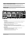
AD168 System Equipment ..............................................................................................................1-2
Equipment That Operators Use......................................................................................................1-2
Equipment That Controls AD168....................................................................................................1-3
Peripheral Equipment ....................................................................................................................1-3
CHAPTER 2: USING A KEYBOARD CONTROLLER .................................................2-1
Keyboard Layout.............................................................................................................................2-1
Keyswitch Positions .......................................................................................................................2-3
Logging on to AD168 ......................................................................................................................2-4
Using Passwords ...........................................................................................................................2-4
Partitioning ....................................................................................................................................2-4
Log On ..........................................................................................................................................2-4
Log Off ..........................................................................................................................................2-4
Basic Keyboard Operations (Keyswitch Off).................................................................................2-5
Monitor Text Overlays ...................................................................................................................2-5
Calling a Monitor to your Keyboard ................................................................................................2-6
Calling a Camera to the Monitor under Keyboard Control ..............................................................2-6
Camera Control Functions .............................................................................................................2-6
Pan/Tilt or Dome Control ...............................................................................................................2-6
Zoom Control.................................................................................................................................2-7
Focus Control ................................................................................................................................2-7
Iris Control .....................................................................................................................................2-7
Calling a Preset (Target) Camera Scene........................................................................................2-7
Activating an Auxiliary ...................................................................................................................2-7
Operating Tours.............................................................................................................................2-8
Starting a System Tour...............................................................................................................2-8
Controlling Tours ...........................................................................................................................2-8
Changing a Tour’s Direction .......................................................................................................2-8
Holding a Tour ...........................................................................................................................2-8
Calling Camera Salvos ..................................................................................................................2-9
Acknowledging Alarms...................................................................................................................2-9
Table of Contents
iii
Camera Lockout .......................................................................................................................... 2-10
APPENDIX A: AD168 SYSTEM DEFAULTS .............................................................. A-1
Keyboard Control:......................................................................................................................... A-1
Basic Programming Defaults: ....................................................................................................... A-1
Full-Scale Programming Defaults: ................................................................................................ A-2
APPENDIX B: ON-SCREEN STATUS LINE DISPLAYS ............................................ B-1
Normal System Operation............................................................................................................. B-1
APPENDIX C: PRINTER MESSAGES ........................................................................ C-1
Alarm Messages ........................................................................................................................... C-1
Alarm Status Categories............................................................................................................ C-1
Video Loss Messages ................................................................................................................... C-1
Video Status Categories............................................................................................................ C-1
Sync Status Categories ............................................................................................................. C-1
Video Loss Detection Mode....................................................................................................... C-1
Menu Access / Exit Messages....................................................................................................... C-2
Power Status Message ................................................................................................................. C-2
APPENDIX D: SPEEDDOME SERIES PROGRAMMABLE COMMANDS.................. D-1
APPENDIX E: SOFTWARE LICENSE AGREEMENT ................................................ E-1
GLOSSARY................................................................................................................. G-1
INDEX............................................................................................................................I-1
iv
AD168 System Operator’s Manual
About This Manual
The AD168 system operator’s manual provides detailed information about AD168’s features, operation,
and application. It explains step-by-step the tasks that you - the operator - will perform when using the
AD168 system. It is designed to be a continuing reference source as you use the AD168 system.
How to Use This Manual
This manual is organized as follows:
•
Chapter 1: “About the AD168 Video Switching System” describes what AD168 does and how it is
used. It also identifies the equipment installed and used with the AD168 system, and discusses your
role as a system operator.
•
Chapter 2: “Using a Keyboard Controller” discusses the use of the AD2078A keyboard to perform
AD168 operations - from camera and auxiliary output control to handling incoming alarm signals.
•
Appendix A, “AD168 System Defaults” lists the programming defaults for the AD168 system
software.
•
Appendix B, “On-Screen Status Line Displays” describes the text messages which appear on monitor
screens during normal system operations.
•
Appendix C, “Printer Messages” lists the messages available for output to a printer connected to the
AD168 central processing unit.
•
Appendix D, “SpeedDome Series Programmable Commands” lists commands applicable for AD168
systems that use SpeedDome and SpeedDome Ultra units as video inputs.
•
Appendix E, "Software License Agreement" describes the terms and conditions under which AD168
software is licensed to the customer.
•
Glossary - the glossary provides concise definitions of a range of the technical terms used in this
document. We recommend that you consult this section if you are unfamiliar with the vocabulary of
video switching technology.
Related Documents
Other sources provide supplemental information about AD168
•
AD168 Installation and Service Manual, document number 8000-0934-01
•
AD168 System Administrator’s Manual, document number 8000-0935-01
•
AD Touch Tracker® Operator’s Manual, document number 8000-1657-02
If you need additional copies of the AD168 System Operator’s Manual, or any other support
documentation, contact your AD sales representative. The document number for this manual is 80000936-01.
AD168 Support Services
AD provides a variety of support services to help you use your system most effectively. If you have a
question about AD168 operation and cannot find the answer in this document, consult your system
administrator. If your question remains unanswered, contact AD technical support at 1-800-442-2225.
System Training and Consultation Services
If you feel that you require additional training beyond that administered by your Customer Support
Specialist or Customer Engineer, contact your supervisor or local AD sales representative to learn about
supplemental training options.
About This Manual
v
vi
AD168 System Operator’s Manual
Chapter 1: About the AD168 Video Switching System
This chapter briefly discusses your role as an AD168 system operator, describes the features and
capabilities of the AD168 system, and identifies the equipment the AD168 system supports.
System Overview
AD168 is a video matrix switching system. The system is comprised of the following major components:
•
Video Inputs - These are the cameras that are installed at your facility. They keep watch on the key
security areas at your site. Some of the cameras are installed in a fixed position and provide a
single, unchanging view. Other cameras, often enclosed in domes, have the ability to move from
side to side and up and down, and can also zoom and focus. These pan/tilt cameras provide a wide
variety of viewing possibilities. They can be pre-programmed to show specific shots and viewing
patterns on immediate demand, and their movements can be controlled freely from authorized
operator keyboards. System cameras are often associated with alarm contacts and auxiliaries. The
alarm contacts respond to system events like the opening of doors or windows, or motion detected in
a restricted zone. When an alarm is activated, the associated camera alarm scene is available for
immediate viewing and response by system operators. Auxiliaries are relay switches that control the
“on” and “off” state of devices that are situated in a camera’s viewing area. System operators can
use auxiliaries to open and close doors and gates, turn lights off and on, and switch emergency
signals.
•
Video Outputs - These are the video monitors and recorders that are located in the workstations at
your facility. The monitors allow system administrators and operators to watch system events in real
time, and respond promptly with appropriate actions. VCRs provide a visible record of events that
occur over extended intervals, and back up the real time observations of system personnel.
•
The AD168 Switching Bay - The switching bay contains the brains of the AD168 system. The bay
enables any video input to be switched to any video output, such that operators can watch different
camera scenes cycle in sequence on a single monitor, or watch multiple scenes shown
simultaneously on a group of monitors. The bay’s processor enables programming of the automatic
display of various camera sequences at different times of day, along with appropriate alarm and
auxiliary responses. The bay is mounted on a rack in a centrally convenient location in your facility.
Camera and monitor cables are routed into and out of the bay, along with data cables that
communicate with other devices that aid in system monitoring and control.
•
The Workstations - The workstations are where system administrators and operators perform their
system setup, monitoring, and control functions. Using their keyboards, operators can “call” cameras
to view on workstation monitors, and control camera movements with key commands. An operator
may control video switching manually, or observe and respond to automatic video sequences. The
number of operators, keyboards, and monitors in a given workstation will vary according to system
requirements. The AD168 system can accommodate up to 168 cameras, 24 monitors, and 32
keyboards at a single site, but a workstation can be as simple as a VCR in a locked closet, recording
events during off-hours.
About the AD168 Video Switching System
1-1
AD168 System Features
The AD168 system enables you to oversee activities throughout your facility as they occur. This powerful
monitoring capability allows you to respond to events promptly, and coordinate with other personnel to
provide optimal site security.
Features available to AD168 operators include the following:
•
matrix switching - selecting workstation monitors for video display, and subsequent selection of
system cameras to view on the monitors.
•
camera control - the ability to adjust a camera’s pan and tilt movements and its lens settings with
simple commands on your keyboard.
•
preset (target) callup and viewing - the ability to callup pre-programmed camera positions for
cameras with pan/tilt and motorized lens capability.
•
tour activation and control - the ability to run pre-programmed camera sequences in forward or
reverse order. The ability to a hold a tour on a single camera, and then control the camera’s
movements for optimal response to an on-going event.
•
salvo call-up - the ability to call multiple camera scenes for simultaneous display on a group of
monitors.
•
auxiliary control - the ability to control switches that perform actions such as opening doors, closing
gates, turning lights on and off, etc. with keyboard commands.
•
pattern callup and viewing - if your system is equipped with SpeedDome series domes, you can run a
pre-programmed pattern of camera views. For example, pattern viewing allows easy observation of
someone entering through a doorway, and then tracking that person’s movements through a hallway.
•
alarm acknowledgment - the ability to recognize system alarm conditions as they occur, and the
means to clear the alarms and initiate an appropriate security response.
AD168 System Equipment
Each AD168 system is made up of a unique set of equipment determined by site requirements. Some of
the equipment discussed below is necessary, and some is optional. System equipment falls into one of
the following categories:
•
Equipment that operators use
•
Equipment that controls the AD168 system
•
Peripheral equipment
Equipment That Operators Use
As a system operator, your first concern is with the equipment you use hands-on. For the AD168 system
this equipment is the AD2078A keyboard controller and the workstation monitors.
•
The AD2078A keyboard controller is the device you use to select monitors and cameras, and control
camera movements. With the AD2078A you can make zoom, focus, and iris adjustments on system
cameras, and can call up pre-defined camera views and patterns. You can control switched outputs,
and clear alarms. The AD2078A is covered in detail in Chapter 2 of this document.
•
The workstation monitors are where the camera video signals are displayed. Monitors connected
from the system’s switching bay will have a text overlay which provides information about the
displayed video. Dedicated monitors, connected directly to cameras via coaxial cable, typically
display video alone.
•
VCRs are typically part of the workstation environment for both time-lapse and real time recording.
1-2
AD168 System Operator’s Manual
•
The AD Touch Tracker is another keyboard which can control system functions. It duplicates the
functionality of the AD2078A but has a different key layout and design. Instructions in this document
will refer to the 2078A. For information about the Touch Tracker refer to the AD Touch Tracker
Manual, document number 8000-1657-02.
Equipment That Controls AD168
The equipment that enables you to perform complex video switching functions with simple key
commands is the AD168 switching bay. The bay contains central processing and power supply circuits,
and modules that connect to the system cameras and monitors. An optional bay module is available
which connects directly to domes and pan/tilt cameras without the need for interface devices. The bay is
mounted on a rack at a centrally convenient location, and connects to all system keyboards. Connections
to, and servicing for the bay should only be performed by qualified technical personnel.
For full-scale operations, bay programming is initially set up and edited by the system administrator using
a PC and software provided by American Dynamics. Small scale operations can be programmed by the
administrator or an authorized operator directly from an AD2078A or Touch Tracker. System keyboard
programming is performed in concert with a program monitor connected to the switching bay.
The bay is connected to a system printer which automatically outputs hard copy system status
messages. Printer documentation provides an important record of system events in the order in which
they happen.
Peripheral Equipment
Other devices that may be connected to the switching bay include the following:
•
Alarm interface units
•
Auxiliary interface units
•
Code distribution, conversion, and translation devices used for the control of pan/tilt cameras and
programmable domes.
•
Port expanders which enable the connection of additional system keyboards.
•
Receiver / Drivers used for the control of pan/tilt cameras
Depending on the requirements of your facility, additional special input devices may be required. Motion
detectors, twilight sensors, and smoke detectors provide a few examples of such devices.
About the AD168 Video Switching System
1-3
1-4
AD168 System Operator’s Manual
Chapter 2: Using a Keyboard Controller
The AD168 system can be controlled by one of two keyboards: the AD2078A or the ADTT Touch
Tracker. Keyboard operation discussed in this document will be expressed in terms of the 2078A key set.
For information on the ADTT Touch Tracker, refer to document number 8000-1657-02.
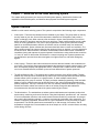
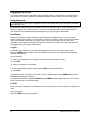
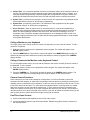
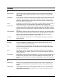
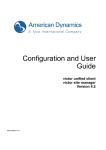
Keyboard Layout
The AD2078A keyboard is comprised of the following sections:
a)
g)
STATUS
MONITOR
CAMERA
ENTER
AUXILIARY
E
N
T
E
R
OFF
ON
PRESET
E
X
I
T
CALL
SET
LL
LL
IRIS
F1
OFF
F2
LAST
ARM
B-PAS
ACK
1
2
3
P
A
CLOSE
G
E
↑
LL
4
USER
SITE
PROG
NEXT
RUN
5
SALVO
MONITOR
CAMERA
0
CLEAR
c)
d)
e)
FAR
→
ZOOM
↑
WIDE
TELE
↓
LL
DISP
b)
NEAR
LL L
9
OFF
PROG
h)
FOCUS
←
8
LL
P
A
G
E
↓
6
HOLD
7
OPEN
f)
i)
a) Status Section The STATUS display window shows information related to satellite installations (not supported in the
current release).
The F1 and F2 keys are special function keys used to execute a set of double key commands.
The USER key is used when logging on and off.
The SITE key selects a site number in satellite switching operations.
b) Keyswitch - The keyswitch has three positions:
OFF enables the operator to perform basic system monitoring and control functions.
PROG enables the administrator to perform a limited set of programming functions.
DISP enables the administrator to perform a wider range of programming functions selected through
a monitor display.
c) Monitor Section The MONITOR display window shows the number of the monitor under keyboard control.
The OFF key disarms a monitor from providing an alarm display.
The ARM key arms a monitor for alarm display.
The PROG key creates monitor tours and accesses program menus.
The MONITOR key selects a specified monitor for control.
Using a Keyboard Controller
2-1
d) Camera Section The CAMERA display window shows the number of the camera currently shown on the monitor
under keyboard control.
The LAST key calls the last previous camera displayed in a sequence.
The B-PAS key removes a camera from a sequence.
The ACK key acknowledges (clears) alarms from monitor screens, and starts system tours.
The NEXT key calls the next camera in a sequence.
The RUN key runs a camera sequence.
The HOLD key holds a sequenced camera on the monitor screen.
The SALVO key calls a pre-programmed salvo of camera scenes.
The CAMERA key selects a specified camera for view on the monitor under control.
e) Keypad Section The ENTER display window shows values entered on the numeric keypad.
The numeric keypad is used to enter numbers representing cameras, monitors, auxiliaries, etc.
The CLEAR key clears numeric data from the ENTER display window.
f)
Dual Function Section note: the first member of each function pair is used with the keyswitch in the
OFF position. The second member of the pair is used with the keyswitch in the DISP position.
The OFF key turns off a specified auxiliary. ENTER stores data for a menu function.
ON turns on a specified auxiliary. EXIT exits a menu function.
CLOSE closes an iris to restrict light to a camera. The PAGE up arrow displays the last previous
page of a menu.
OPEN opens a camera iris to allow more light to the camera. The PAGE down arrow displays the
next page of a menu.
The NEAR key focuses the camera for near objects. The left arrow moves the cursor one character
to the left in a menu.
The FAR key focuses the camera for distant objects. The right arrow moves the cursor one character
to the right in a menu.
The WIDE key zooms out for a wide angle camera view. The up arrow moves the cursor up one line
in a menu.
The TELE key zooms in for a telephoto camera view. The down arrow moves the cursor one line in a
menu.
g) Preset Section The CALL key calls a specified preset scene (keyswitch in "off" position).
The SET key sets a particular scene as a preset (keyswitch in "prog" position).
h) Recessed Speaker - Provides an audio alarm tone.
i)
2-2
Joystick - Enables movement of cameras with pan/tilt capabilities.
AD168 System Operator’s Manual
Keyswitch Positions
The AD2078A keyboard controller allows complex video switching operations to be accomplished with a
set of relatively simple key commands. System operators will perform many of these operations in the
normal course of their shifts, depending on their scope of system access as defined by the system
administrator.
The AD2078A’s keyswitch enables three operating positions, “OFF”, “PROG”, and “DISP”. The key can
be removed only when turned to the “OFF” position. With the key removed, operators can perform the
following functions without changing system parameters originally set up by the administrator or system
installer.
•
log on and off to the AD168 system.
•
call a monitor.
•
call a camera to the monitor under keyboard control
•
control of pan, tilt, zoom, focus, and iris adjustments
•
call presets
•
activate auxiliaries
•
operate and control tours
•
call salvos
•
acknowledge alarms
The remainder of this chapter will discuss fundamental keyboard operations.
This manual covers only those keyboard functions which are performed with the keyswitch in the “OFF”
position. If authorized by a system administrator, an operator can perform certain keyboard setup and
system programming functions. For information about keyboard operation beyond the scope of this
manual, please consult your system administrator.
Using a Keyboard Controller
2-3
Logging on to AD168
This section describes how to get started using the AD168 system. It discusses the use of passwords to
gain access to the system, and how your password defines the level of access you have to the system.
Using Passwords
If your workstation does not require operators to log on to the system with unique passwords, this section
does not apply to you.
If passwords are mandatory at your workstation, you will be required to log on to your keyboard controller
before you begin to use it. When you log on, you enter a six digit passcode on the numeric keypad of
your keyboard. The passcode has been pre-assigned to you by your system administrator.
Partitioning
Depending on which one of the workstation keyboards has been assigned to you, you may not have
access to certain video monitors. On the monitors of which you have free access, some system cameras
may not be viewable. Additionally, you may be able to view certain cameras, but not control their
movements. Such monitor and camera restrictions are referred to as partitioning. Partitioning decisions
are programmed by your system administrator.
Log On
If passcode entry is required on your 2078A keyboard, the letters “UC” (user code) appear in the
keyboard CAMERA display window. This code indicates you must enter your passcode before gaining
control of the keyboard.
Log on procedure:
1) enter your pre-assigned user number (1-64) on the keyboard’s numeric keypad.
2) press ACK.
3) enter your passcode on the keypad.
If an incorrect password has been entered press CLEAR, and then repeat step 3.
4) press ACK.
If the passcode does not verify, a tone sounds, and “UC” appears again in the CAMERA display. Press
CLEAR and repeat steps 1 through 4.
If the passcode verifies, the keyboard MONITOR and CAMERA display windows will clear. This confirms
that you have access to the AD168 system.
Log Off
When your shift is completed, it is advisable to log off from the system to prevent access to unauthorized
users.
Log off procedure:
Press the USER key (log off is complete).
2-4
AD168 System Operator’s Manual
Basic Keyboard Operations (Keyswitch Off)
The following functions are performed with the keyswitch in the OFF position.
•
Calling a monitor to the keyboard
•
Calling a camera to the monitor under keyboard control
•
Controlling camera movements
•
Calling preset camera scenes
•
Activating auxiliary switches
•
Operating and controlling pre-programmed tours
•
Calling pre-programmed camera salvos
•
Acknowledging Alarms
•
Locking Out Cameras
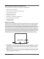
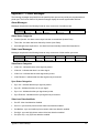
Monitor Text Overlays
The workstation monitors display the video from the cameras installed at your site. Each monitor has an
identification number associated with it based on its physical connection point on the AD168 switching
bay. In addition to the camera video, switching monitors also display a text overlay which provides
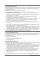
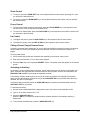
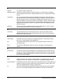
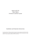
information about the camera view being displayed. The illustration below shows the basic format of the
monitor screen text overlay. The standard monitor title and time/date display has a format of two rows
with 24 characters per row. The monitor number/status section consists of 2 rows with a maximum of 7
characters per row. The camera/preset title section consists of 2 rows with a maximum of 8 characters
per row. The date and time section consists of 2 rows with a maximum of 8 characters per row. There is
always 1 blank character on both of the 2 rows inserted between the camera/preset title section and the
time/date section. The alarm title area appears above the standard display, and consists of 2 rows
having 24 characters each. All 48 character positions in the alarm title area can be used if required.
ALARM TITLE AREA
ABOVE TEXT OVERLAY
a)
b)
0001
HOLD
NORTH
HALLWAY
10:27:53
12-15-96
f)
d)
e)
c)
a) Camera Number - this identifies the camera being viewed. The number will either be a real number
corresponding to the camera’s physical connection point on the AD168 switching bay, or a pseudo
number, which is a convenient substitute for the real number that gives a clue as to the camera’s
location or functions.
b) Status Line - this shows the current status of the camera being viewed. Status information includes
camera dwell times, alarm information, tour status, etc. A complete listing of status line displays is
included in Appendix B of this document.
Using a Keyboard Controller
2-5
c) Camera Title - the camera title provides two lines of information relating to the camera’s location or
function. The camera title is pre-programmed by the system administrator using S³ software, or by
using AD168 menu programming. If a preset (target) title is programmed for a given camera, the
preset title will replace the camera title at the time that the preset scene is called to the monitor.
d) System Time - provides the current time in 24 hour format. The system time is programmed by the
system administrator using S³ or AD168 menu programming.
e) System Date - provides the current date. This information is also programmed by the system
administrator using S³ or AD168 menu programming.
f)
Alarm Title Area - When an alarm occurs on an armed monitor, it may be accompanied by a
message which will appear directly above the text overlay information discussed in a) through e)
above. The alarm message consists of two lines of text, with each line consisting of up to 24
characters of text. The alarm message will be displayed on a red background field. In order for a
message to appear with alarm video, an alarm title must be programmed through S³ setup software
by a system administrator.
Calling a Monitor to your Keyboard
To bring a system video monitor under the control of a keyboard, you must “call” the monitor. To call a
monitor to a keyboard:
1) Enter the monitor’s number on the keyboard’s numeric keypad. The number will appear in the
ENTER display window.
2) Press the MONITOR key. The monitor’s number will appear in the MONITOR display window (if a
camera has previously been called to the monitor, that camera's number will appear in the CAMERA
display window).
Calling a Camera to the Monitor under Keyboard Control
To view a system camera scene, you must call the camera to the monitor currently under the control of
the keyboard. To call a camera:
1) Enter the camera’s number on the keyboard’s numeric keypad. The number will appear in the
ENTER display window.
2) Press the CAMERA key. The camera’s number will appear in the CAMERA display window. The
camera’s video signal and corresponding text overlay will appear on the monitor screen.
Camera Control Functions
Some cameras at your site will be installed in a fixed position. You will not be able to control the
movement of these cameras, or adjust their lens settings. Cameras that have pan/tilt and motorized lens
capability can be controlled from your keyboard. To pan is to move the camera from side to side. To tilt is
to move the camera up and down. To zoom refers to the apparent action of moving closer to or farther
away from an object, as seen through the camera lens. To focus refers to the action of adjusting the
clarity of the picture on the monitor. If you wish to brighten the picture on your monitor, you will want to
open the camera’s iris to allow more light in the camera. If you wish to darken the monitor picture you will
want to close the iris to restrict the amount of light coming into the camera.
Pan/Tilt or Dome Control
1) Call a camera with pan/tilt capability to the monitor under control.
2) Use the keyboard’s joystick to pan and tilt the camera. Release the joystick when the camera is in
the desired position.
2-6
AD168 System Operator’s Manual
Zoom Control
1) To zoom in, press the ZOOM TELE key in the keyboard’s dual function section (see page 2-1) until
you achieve the desired picture.
2) To zoom out, press the ZOOM WIDE key in the keyboard’s dual function section until you achieve
the desired picture.
Focus Control
1) To focus on an object located at close range, press the FOCUS NEAR key in the keyboard’s dual
function section, until you achieve the desired clarity.
2) To focus on a distant object, press the FOCUS FAR key in the keyboard’s dual function section until
you achieve the desired clarity.
Iris Control
1) To brighten the picture, press the IRIS OPEN key on the keyboard’s dual function section.
2) To darken the picture, press the IRIS CLOSE key the keyboard’s dual function section.
Calling a Preset (Target) Camera Scene
A preset is a camera scene whose pan, tilt, zoom, and focus positions are stored in memory, and which
can be called to a monitor with simple keyboard commands. Presets are sometimes referred to as
targets.
To call a preset scene:
1) Call a camera with pan/tilt and motorized lens capability to the monitor under control.
2) Enter the preset number (1-72) on the numeric keypad.
3) Press the CALL key in the keyboard’s PRESET section. The preset scene will appear on the monitor
screen.
Activating an Auxiliary
An auxiliary is a relay switch which controls the “on/off” state of devices such as door locks, lights, and
gates. Auxiliaries are associated with cameras within the AD168 system, and can be controlled by the
AUXILIARY ON and OFF keys through the keyboard controller.
A momentary auxiliary remains active as long as its control key pressed. An example of momentary
action is a door that remains unlocked as long as the AUXILIARY ON key is pressed. When the key is
released, the door is locked again.
A latched auxiliary is activated when the AUXILIARY ON key is pressed, and de-activated when the
AUXILIARY OFF key is pressed.
To activate an auxiliary:
1) Call the camera associated with the appropriate relay to the monitor under keyboard control.
2) Type in an auxiliary number from 1 to 3.
3) Press the AUXILIARY ON key.
When the ON key is released, a latched auxiliary remains activated. A momentary auxiliary is
deactivated.
4) To de-activate a latched relay, press the AUXILIARY OFF key.
Using a Keyboard Controller
2-7
Operating Tours
A tour is a pre-programmed sequence of camera scenes that appear one after the other on monitor
screens. A monitor tour is a temporary or "scratch pad" tour programmed through the monitor section of
the keyboard controller. A system tour is a tour programmed by the system administrator as an integral
part of the system setup procedure. System tours can be called and controlled through a keyboard
controller with the keyswitch in the OFF position.
Starting a System Tour
1) Call the monitor which will display the tour.
2) Enter the system tour number (1-64) on the numeric keypad.
3) Press the RUN key in the CAMERA section of the keyboard. You are then prompted on the monitor
screen to press ACK.
4) Press the ACK key within two seconds of pressing the RUN key.
If the ACK key is not pressed within the two second interval, repeat the procedure from step 2. Note:
once a system tour is acknowledged, it becomes the current monitor tour. The tour can be modified
on the called monitor without changing the original definition of the system tour.
Controlling Tours
Once any tour is started, it is operated and controlled in the same way, regardless of its definition
(monitor or system tour), and regardless of how it was started (through an operator’s keyboard action, or
through automatic, pre-programmed system timing). The tour cycles continuously until an operator holds
the tour, or until another camera scene or tour is called to the monitor.
•
While a tour is running, the monitor status line shows the dwell time for each scene as it is shown in
the sequence. The dwell time is simply the duration of each scene in the sequence, and can vary
from scene to scene. A dwell time can range from 1 to 60 seconds. A dwell setting of 61 instructs the
tour to hold (stop) on the camera scene to which it is assigned.
•
When a tour is running in the forward direction, an “F” is displayed beside the dwell time.
•
When a tour is running in the reverse direction, an “R” is displayed beside the dwell time.
Changing a Tour’s Direction
•
Press the NEXT key in the keyboard’s section to change the tour to forward direction.
•
Press the LAST key in the keyboard’s CAMERA section to change the tour to reverse direction.
Holding a Tour
•
Press the HOLD key in the keyboard’s CAMERA section to hold (stop) a tour on the currently
displayed camera scene While a tour is held on a camera, keyboard control functions such as pan,
tilt, zoom, focus, iris, preset call, and auxiliary activation can be performed on that camera.
To remove a camera from a tour on hold:
•
Press the B-PAS key on the keyboard’s CAMERA section, and then step to the next camera in either
the forward or reverse direction.
•
Press the NEXT key on the keyboard’s CAMERA section to set the tour to the forward direction.
•
Press the LAST key on the keyboard’s CAMERA section to set the tour to the reverse direction.
•
Press the RUN key in the keyboard’s CAMERA section to resume the tour in the selected direction.
2-8
AD168 System Operator’s Manual
Calling Camera Salvos
A salvo is a group of camera scenes that can be called for simultaneous display on a contiguous group
of monitors. Salvos are programmed by the system administrator through S³ software.
To call a salvo:
1) Enter the number of the first (lowest numbered) monitor in the salvo group on the numeric keypad.
2) Press the MONITOR key in the keyboard’s monitor section. The number will appear in the monitor
display.
3) Enter the salvo number (1-64) on the keyboard’s numeric keypad.
4) Press the SALVO key in the keyboard’s CAMERA section. The salvo will appear on the appropriate
monitor group.
The on-screen status line of each monitor displaying a salvo camera scene shows the word “SALVO”. If
a salvo is called in response to a system alarm, the first monitor of the group will display the word
“ALARM” on the status line. The remaining monitors in the alarm salvo group will display the word
“SALVO” in the status line.
Acknowledging Alarms
System cameras in the AD168 system are associated with alarm contacts connected to key security
points under camera view. If an alarm is activated, the camera scene associated with the alarm will
appear on a system monitor or monitors that are armed for alarm display (alarm contacts are associated
with specific monitors through S³ system setup software). When the alarm camera scene appears on the
monitor screen, the word “ALARM” appears on the monitor’s on-screen status line. If an alarm title has
been programmed by the system administrator, the alarm title will appear in the alarm title area.
Some system monitors are armed for automatic or delayed automatic clearance. Monitors armed for
manual clearance (acknowledgment) can be cleared from a keyboard controller.
To acknowledge an alarm:
1) Call the monitor that is displaying the alarm video.
2) Press the ACK key in the keyboard’s CAMERA section.
To acknowledge an alarm salvo
1) Call the first (lowest numbered) monitor in the alarm group.
2) Press the ACK key.
If a monitor is cycling through a sequence of multiple alarm scenes:
1) Hold on or step to (press NEXT or LAST) the first alarm to be cleared.
2) Press the ACK key.
3) Repeat steps 1) and 2) for each alarm in the sequence
To acknowledge a wired set:
If a wired set (see Glossary) is associated with an alarm contact, call the monitor associated with the
alarm contact and press ACK to clear the alarm. All alarms in the wired set are cleared when this alarm
is cleared.
Using a Keyboard Controller
2-9
Camera Lockout
Cameras can be “locked out” to prevent other keyboard operators from controlling their movements. If a
camera is locked out, other operators will be able to view the camera, but will not be able to control its
pan, tilt, zoom, focus, iris, preset, and auxiliary functions. When an operator calls a camera that has
been locked out, the word “LOCK” appears on the monitor’s status line.
An operator who has the same or lower priority level than the operator who locked the camera out,
cannot control the camera.
An operator with a higher priority level than the operator who locked the camera out, can gain control of
the camera.
To lock or unlock control access to a camera:
1) Call or hold the desired camera on the monitor under your keyboard control
2) Enter either of the following F1 code combinations:
“1 F1” to unlock the camera
“2 F1” to lock the camera
2-10
AD168 System Operator’s Manual
Appendix A: AD168 System Defaults
The following default values are set at system start-up, or through the System Reset function performed
by a system administrator.
Keyboard Control:
All monitors switch to camera 0 (color bar pattern). No monitors are under keyboard control.
Basic Programming Defaults:
Note: Functions listed in the table below are programmable through AD2078A and ADTT Touch Tracker
keyboards.
Function
Default
Date Format
MM-DD-YY
Monitor Display Arrangement
Status, titles, date, and time displayed
on bottom of monitor screen.
Monitor On-Screen Display
All monitors unlocked
Camera Lockout
All cameras unlocked
Camera Video Loss Detection
All cameras set to off. Video loss
detection disabled
Monitor Tour
Monitor tour erased for all monitors
Monitor Arming
All monitors disarmed
Audio Alarm
Audio alarm enabled system wide
Appendix A: AD168 System Defaults
A-1
Full-Scale Programming Defaults:
Note: Defaults marked by an asterisk (*) accessible only through S³ software
System Options
User IDs
Menu Callup
Messages
Disabled. No passcode entry required
No camera number defined
All messages printed. No program monitor output
Time and Date
Set to the time and date of the embedded system software
Ports
Baud Rate:
Port Use
A-2
1200 bps (Ports 1-7) 38.4K bps (Port 8)
Keyboard (Ports 1-7) Terminal (Port 8)
System Tours*
Camera
Dwell Time
Preset
Auxiliary
Connect Next
0
0
0
0
No
System Salvos*
Camera
Preset
Auxiliary
Connect Next
0
0
0
No
Event Timers*
All timers = 24:00. All alarm table entries = 0. No callups set
Alarm Contacts/Cameras*
Dwell Time
Preset
Auxiliary
Connect Next
Contacts assigned in blocks of 180, up to 1024 contacts
2
0
0
No
Alarm Contacts/Monitors*
All positions set to “No”. No alarm contact / monitor association
Monitor Arming*
Arming Code
Block
Disarmed
0
Monitor Status
Tour
Tour Status
Display
None
Hold
Status. Titles, Date, and Time on.
Pseudo Numbers
one-to-one correspondence with real camera inputs (1-180)
Titles (Cameras, Presets, Alarms)
All titles blank
Users / Keyboards
Users:
Keyboards
Priority Levels
Priority level = 8. No passcodes
Priority level = 8
Level = 1, all functions except Override set to Yes
Partitioning*
Keyboard/Monitor
Keyboard/Camera View
Keyboard/Camera Control
Monitor/Camera
All positions set to “Yes”, access allowed
All positions set to “Yes”, access allowed
All positions set to “Yes”, access allowed
All positions set to “Yes”, access allowed
AD168 System Operator’s Manual
Appendix B: On-Screen Status Line Displays
Normal System Operation
The following messages appear on monitor on-screen status lines during normal system operation.
Code
Description
ALARM
Displayed when an armed alarm contact is activated. The message remains on the
monitor until the alarm is cleared.
ACK nn
Displayed when the ACK key is pressed to start a system tour. The message indicates
the tour number selected, and remains displayed until the first camera in the tour is called
to the monitor.
nnF
Displayed during system tour operation. “nn” indicates the dwell time in seconds of the
currently displayed camera, and the letter “F” for a tour running in the forward direction.
nnR
Displayed during system tour operation. “nn” indicates the dwell time in seconds of the
currently displayed camera, and the letter “R” for a tour running in the reverse direction.
HOLD
Displayed during a tour hold. The message indicates that the tour is on hold at the
currently displayed camera.
SALVO
Displayed when a system salvo has been called to the monitor.
IN USE
Displayed when a another keyboard has control of the currently displayed camera.
LOCK
Displayed when the camera has been locked out by another keyboard.
NO CTRL
Displayed when a camera has been called by a keyboard that has been partitioned such
that it cannot control the movements of the camera.
Appendix B: On-Screen Status Line Displays
B-1
B-2
AD168 System Operator’s Manual
Appendix C: Printer Messages
The following messages are printed from the parallel printer port and any serial port programmed as a
printer port. The first two fields of all printed messages display the current system date and time.
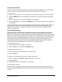
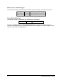
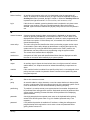
Alarm Messages
Messages are printed in the following format at every occurrence of an alarm event.
Format
Description
05-MAR-
13:23:26
CONTACT 0001
CAM 0001
CONTACT OPENED
date of the
alarm event
time of the
alarm event
alarm contact
activated
camera linked with
alarm event
alarm status
Alarm Status Categories
•
Contact Opened - the alarm contact input has been removed/reset (Instant Clear)
•
Timed Out - the alarm has been cleared by timeout (Auto Clear)
•
Acknowledged from Keyboard nn - the alarm has been manually cleared from keyboard nn
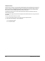
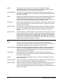
Video Loss Messages
Messages are printed in the following format at every occurrence of video and/or sync event.
Format
05-MAR-1996
13:23:26
CAM 0001
VIDEO YES
SYNC YES
SET LOW
Description
date of video
event
time of
video event
video status
camera number
video status
sync status
video loss
detection mode
Video Status Categories
•
Video Yes - indicates that the video signal is present
•
Video No - indicates that there is no video signal
•
Video Lost - indicates that the video signal was just lost
•
Video Restored - indicates that the video signal was just restored
Sync Status Categories
•
Sync Yes - indicates that the sync signal is present
•
Sync No - indicates that there is no sync signal
•
Sync Lost - indicates that the sync signal was just lost
•
Sync Restored - indicates that the sync signal was just restored
Video Loss Detection Mode
•
Set Off - video loss detection disabled
•
Set Low - sync and low picture content video loss detection enabled
•
Set Medium - sync and medium picture content video loss detection enabled
•
Set High - sync and high picture content video loss detection enabled
•
Set Sync Only - only sync loss detection enabled
Appendix C: Printer Messages
C-1
Menu Access / Exit Messages
The following messages are printed each time that an operator accesses or exits the menu system.
05-MAR-1996
13:23:26
MENUS ACCESS OCCURRED
05-MAR-1996
13:23:26
MENUS EXITED OCCURRED
Power Status Message
The following message is printed each the AD168 system is powered on.
05-MAR-1996
13:23:26
POWER RESTORED
Note: When the MESSAGES TO PROGRAM MONITOR option of the System Options function is
enabled, the messages selected in PRINTER MESSAGES are displayed on the AD168 program monitor
video output (in addition to being printed).
C-2
AD168 System Operator’s Manual
Appendix D: SpeedDome Series Programmable Commands
When used in combination with numeric keypad inputs, the F1 keys on the AD2078A and AD Touch
Tracker keyboards accomplish specific functions related to the operation of SpeedDome, SpeedDome
LT, and SpeedDome Ultra domes. Following is a list of F1 key combinations and their associated
functions.
Keys
Function
Keys
Function
19-F1
Flip Camera Position 180º
33-F1
Go to Pattern # 3
20-F1
Reset Iris
41-F1
Auto Repeat Pattern # 1
21-F1
Run Pattern # 1
42-F1
Auto Repeat Pattern # 2
22-F1
Run Pattern # 2
43-F1
Auto Repeat Pattern # 3
23-F1
Run Pattern # 3
69-F1
Return to Auto Iris / Auto Focus
30-F1
Reset Dome
70-F1
Set Auxiliary 4 OFF
31-F1
Go to Pattern # 1
71-F1
Set Auxiliary 4 ON
32-F1
Go to Pattern # 2
SpeedDome Series Programmable Commands
D-1
D-2
AD168 System Operator’s Manual
Appendix E: Software License Agreement
1.
General. Software is being licensed to the Customer pursuant to the following terms and conditions, which supplement any
purchase or lease agreement (the "Equipment Agreement") between Customer and Sensormatic Electronics Corporation ("SEC").
By accepting receipt of, or by using, such Software, the Customer agrees to be bound by the terms of this Software License
Agreement (the "License Agreement"). The term “Software” means all computer programs, instructions, data and databases, in any
form or on any media, supplied by SEC (or its suppliers) to Customer and all current and future versions, revisions, updates,
upgrades and new releases thereof. Except as otherwise provided in this License Agreement, the terms and conditions of the
Equipment Agreement apply to the Software, the related technical and user manuals ("Documentation") and the license provided
herein.
2.
License. SEC licenses the Software and the Documentation to Customer, for the license fee(s) set forth (or included in the
product prices set forth) in the Equipment Agreement and subject to the terms and conditions of this License Agreement. The
license is non-exclusive and is limited by the terms of this License Agreement. Customer may not transfer the license except to a
party to whom the equipment is transferred and then only with the written consent of SEC. The Software and Documentation are
being licensed and not sold or leased to Customer. SEC or its suppliers who have authorized SEC to sublicense certain of the
Software and Documentation retain ownership of the Software and Documentation. The Software is being licensed for use only on
(i) a single computer (A) owned or leased by Customer and identified in the Equipment Agreement or (B) otherwise identified in the
Documentation as compatible with the Software, or (ii) a back-up machine if and so long as such computer becomes temporarily
inoperable.
3.
Term. The term of the license is perpetual, except that it will terminate automatically if Customer sells or otherwise disposes of the
Software or its related equipment or Customer breaches any provision of this License Agreement or the Equipment Agreement. If
the license terminates, SEC will have the right to take possession of all copies of the Software and Documentation in the possession
of Customer or to require Customer to destroy all such copies and certify such destruction in writing to SEC.
4.
Ownership. Customer agrees and acknowledges that (i) SEC (or its suppliers) is the sole owner of the Software and
Documentation (including all copies thereof, in whatever form or media, delivered to or made by Customer) and all patent, copyright
and other intellectual property rights with respect thereto and (ii) the Software and Documentation constitute valuable trade secrets,
confidential information and proprietary properties of SEC and its suppliers. Accordingly, Customer agrees that it will have no rights
in the Software or Documentation other than those granted under this License Agreement and agrees to abide by the restrictions on
its use of the Software and Documentation set forth in Section 5 of this License Agreement.
5.
Use and Copies. Customer may use the Software and Documentation only in conjunction with the other equipment identified in
the Equipment Agreement, as part of the access control, closed circuit television or other security system being acquired from SEC
and for Customer's internal business purposes. SEC will furnish the Software to Customer solely in object code form.
Customer may make up to 2 copies of the Software solely for back-up and archival purposes. Customer will not remove or modify
the copyright and other proprietary notices and legends of SEC and its suppliers contained in the Software and Documentation and
will reproduce all such notices and legends on all copies of the Software made by Customer. Customer may not make copies of the
Documentation, but may obtain additional copies of the Documentation from SEC at its established rates. Except as permitted
above, copying of the Software and Documentation is forbidden.
Customer will not sell, assign, sublicense or transfer this license or sell or otherwise transfer the Software or Documentation (or any
portion thereof) to others. Customer will maintain the Software and Documentation in confidence and not disclose any data or other
information contained in the Software or Documentation to any party, except for Customer's employees and agents who require
access to the Software for the purposes of Customer's internal business and who use it in accordance with the terms of this License
Agreement. Customer will not use the Software for the provision of time-sharing services to others. Customer will not modify the
Software or decompile, disassemble or otherwise reverse engineer the Software and will not have the right to create derivative works
of the Software, including, without limitation, translated or localized versions of the Software. Customer will not export or re-export
the Software or the Documentation or any portion thereof without appropriate United States or foreign governmental licenses.
6.
Customer will implement appropriate measures, such as the requirement that employees and others permitted access to the
Software enter into appropriate non-disclosure agreements, to satisfy its obligations hereunder and, generally, will treat the Software
and Documentation with the same degree of care and confidentiality which Customer provides for its own confidential information.
Customer acknowledges that it may be held legally responsible for any copyright infringement or trade secret violation that is caused,
in whole or in part, by its failure to abide by the terms of this License Agreement. Since unauthorized transfer, use or disclosure of
the Software and Documentation would diminish their value to SEC and its suppliers, who would have no adequate remedy at law if
Customer breaches its obligations under this License Agreement, SEC and its suppliers (who are direct and intended beneficiaries
of this License Agreement) will be entitled to injunctive relief, in addition to such other remedies and relief that would be available to
them in the event of such a breach.
Limited Warranty; Limitation of Liability. The provisions of the Equipment Agreement respecting maintenance and warranty will
not apply to the Software or the Documentation, unless specifically stated otherwise and agreed to in writing by both parties. SEC's
sole warranties with respect to the Software and Documentation are that (i) SEC has title to the Software and Documentation and/or
the right to grant Customer the license set forth in this License Agreement and (ii) the magnetic media on which the Software is
recorded is free from defects in materials and workmanship under normal use. SEC's sole obligation under this warranty will be to
Software License Agreement
E-1
replace any defective media returned to it free of charge. The period of this warranty will be 12 months from the date of the
Equipment Agreement (the “Warranty Period”).
EXCEPT AS SET FORTH IN THIS SECTION 6, SEC DISCLAIMS ANY WARRANTY, EXPRESS OR IMPLIED, WITH
RESPECT TO THE SOFTWARE OR THE DOCUMENTATION OR THEIR OPERATION OR USE, INCLUDING, WITHOUT
LIMITATION, ANY IMPLIED WARRANTY OF MERCHANTABILITY OR OF FITNESS FOR A PARTICULAR PURPOSE OR
USE. SOME STATES DO NOT ALLOW THE EXCLUSION OF IMPLIED WARRANTIES, SO THE ABOVE EXCLUSION DOES
NOT APPLY IN SUCH STATES. THIS WARRANTY GIVES YOU SPECIFIC LEGAL RIGHTS, AND YOU MAY ALSO HAVE
OTHER RIGHTS THAT VARY FROM STATE TO STATE.
SEC AND ITS SUPPLIERS, EMPLOYEES, AGENTS AND FRANCHISEES WILL IN NO EVENT BE LIABLE FOR ANY
INCIDENTAL, CONSEQUENTIAL OR OTHER DIRECT OR INDIRECT DAMAGES (FOR LOSS OF BUSINESS INFORMATION
OR PROFITS OR OTHERWISE) SUFFERED BY CUSTOMER, ANY OF ITS EMPLOYEES OR AGENTS OR ANY OTHER
PERSON ARISING OUT OF OR IN CONNECTION WITH THE USE OR INABILITY TO USE THE SOFTWARE OR THE
DOCUMENTATION, OR THE MAINTENANCE OR SUPPORT THEREOF, EVEN IF THEY HAVE BEEN ADVISED OF THE
POSSIBILITY OF SUCH DAMAGES. SEC neither assumes nor authorizes any employee, agent or franchisee to assume for SEC
any other liability in connection with the license, use or performance of the Software or Documentation.
Customer is solely responsible for the selection of the Software to achieve Customer’s intended results, for the conformity of the
computer on which the Software is run to SEC’s specifications or requirements and for the maintenance of such computer in good
working order and repair. SEC’s suppliers do not warrant the Software, assume any liability regarding the use of the Software or
undertake to provide any maintenance, support or information regarding the Software.
7.
U.S. Government Restricted Rights. The Software and Documentation are provided with restricted rights. Use, duplication or
disclosure by the U.S. Government is subject to restrictions as set forth in subparagraphs (c)(1)(ii) of the Rights in Technical Data
and Computer Software Clause of Department of Defense Federal Acquisition Supplement (DFARS) 252.227-7013 or in
subparagraph (g)(3)(i) of Federal Acquisition Regulations (FAR) 52.227-14, Alternate III, as applicable.
8.
Indemnity. SEC will defend and hold Customer harmless from any claim, action, suit or proceeding brought against Customer to
the extent that it is based on a claim that the use of the Software, as such, in accordance with this License Agreement and not as a
result of the combination thereof with any other article, computer software or process, constitutes an infringement of any United
States patent or copyright or the violation of any trade secret, if SEC is notified thereof promptly after its commencement and is
given control of the defense thereof and any negotiations for its settlement and full cooperation by Customer.
SEC will pay all damages and costs awarded against Customer in connection with any such claim, except that SEC will not be liable
for any amounts paid under any compromise or settlement made without its consent. If the Software is either claimed or held to
infringe or violate any patent or copyright, SEC may, at its sole option and expense, and Customer will permit SEC to, procure for
Customer the right to continue using the Software or modify it so that it becomes non-infringing or replace it with a non-infringing
counterpart. If neither of such alternatives is available on terms which are reasonable in SEC's judgment, Customer will return all
copies of the Software and Documentation in the possession of Customer to SEC, at SEC's request, and SEC will refund a
reasonable portion of the license fees paid by Customer to SEC. This Section 8 sets forth SEC's entire liability regarding
infringement and the like.
E-2
AD168 System Operator's Manual
Glossary
A
alarm contact
A sensor which, when activated, signals a change from normal system operation.
Alarm contacts are associated with cameras or camera salvos in programmable
alarm tables.
alarm table
A table written in computer memory which associates alarm contacts (sensors) with
cameras or and/or camera salvos. The table includes information about camera
dwell times, preset numbers, auxiliary status, alarm title numbers, camera linking
status, and alarm scene locations.
arming
Arming is the process by which a video monitor or monitor block is associated with a
specific alarm contact, and is assigned an appropriate monitor arming code.
arming code
A monitor’s arming code defines how an alarm scene will be displayed, queued, and
cleared on the monitor. Display methods include Single, Dual, and Block. Queuing
methods include Hold and Sequence. Clearance methods include Instant, Auto, and
Manual.
auto clearance
Automatically clears the alarm camera scene 20 seconds after the associated alarm
contact is reset at its source location. If the alarm is set again within the 20 second
interval, it does not clear (for example, a door equipped with an alarm sensor is
opened, closed, and opened again within 20 seconds).
auxiliary
A relay switch which controls the “on” or “off” state of devices such as door locks,
gates, and lights.
B
baud rate
A rate of transmission measured by the number of bits per second sent over a
computer-controlled communications line.
bay
An enclosure containing the electronics modules and bus circuitry necessary to
perform switching system functions. The AD168 system is available in both single
and dual bay configurations.
block
A contiguous group of video monitors. Contiguous is defined as an uninterrupted
integer sequence. For example, monitors 1,2,3,4, and 5 are contiguous. Monitors 1,
3, 5, and 7 are not.
block display
Multiple alarm camera scenes are displayed on the block of monitors with which they
are associated. The lowest number of the block displays the first alarm scene, the
second lowest numbered monitor of the block displays the second alarm scene, and
so on.
C
camera lock
camera lock is a programmable function which prevents a user or keyboard from
controlling camera pan/tilt and lens adjustments, preset positioning, and auxiliary
actions.
connect next
“Connect Next” refers to a set of linking options used with tours, salvos and alarm
contact tables, which defines how each salvo, tour, or alarm contact table entry is
connected to the next entry.
Glossary
G-1
D
data bits
The number of bits in a data word.
dedicated monitor A monitor connected directly to a specific camera via coaxial cable. A dedicated
monitor displays the video from a single camera input only. Compare with switching
monitor.
dual display
Two or more alarm camera scenes are displayed on the two monitors with which
they are associated. The two monitors are defined, respectively, as the hold monitor,
and the sequence monitor. The hold monitor displays the first alarm received. All
subsequent alarms are queued for display on the sequence monitor. When an alarm
scene is cleared from the hold monitor, it is replaced by the alarm scene previously
displayed on the sequence monitor. The sequence monitor then displays the next
scene in its queue.
dwell time
The amount of time an individual camera scene is displayed on a monitor screen
before being replaced by the next scene in sequence.
E
event timer
A programmable time slot which associates tours, monitors, and alarm contact
tables with specific times of day and specific days of the week. 35 event times are
available in the AD168 system.
F
fixed camera
A camera which views a scene from a single perspective. A fixed camera cannot
pan or tilt, or make automatic lens adjustments.
flip
To instantaneously position a dome 180° in the opposite direction of where it is
currently pointing.
focus
The process of adjusting the clarity of a scene or an object, as seen through a
camera.
H
hold queuing
The first alarm camera scene displayed on its associated monitor is held there until
the alarm is cleared. Subsequent alarms are queued behind the first alarm, pending
its clearance. As each displayed alarm is cleared, the next scene in queue takes its
place on the monitor display.
I
input
A device such as a door contact, a smoke detector, or a twilight sensor, that, when
configured to do so, can activate an alarm when it undergoes a change of state.
instant clearance
Automatically clears the alarm camera scene immediately after the associated alarm
contact is reset at its resource location (this entails opening or closing a switch, and
can be as straightforward as closing an opened door).
iris
The camera component that determines how light enters the camera. By adjusting
the iris, you can adjust the brightness and darkness of the video on the monitor.
G-2
AD168 System Operator’s Manual
L
latched auxiliary
An auxiliary that remains active until it is deactivated using the appropriate off
switch. An example of a latched auxiliary is a light. When the keyboard controller’s
Auxiliary On button is pressed, the light is turned on. When the Auxiliary Off button
is pressed, the light is turned off. See also auxiliary and momentary relay.
log in
If this function is enabled, system keyboard access is restricted to only those users
entering a user number (1-64) and a six digit passcode. When the function is
disabled, system access is restricted only by the priority level set for the keyboard in
use.
M
manual clearance
A system operator clears the alarm scene when it is displayed on its associated
monitor by pressing the ACK key on the AD2078A or ADTT Touch Tracker. If the
displayed alarm camera scene is a member of a wired set, and is programmed with
the connect next option of “Wired Group Ack”, all members of the wired set will be
cleared simultaneously.
menu callup
The menu callup function identifies the video input that the program monitor output
is connected to. Menu callup allows an administrator to call the video input to any
system monitor. By turning the AD2078A keyswitch to the "DISP" position, the
administrator can then perform menu programming using the system monitor.
monitor
The screen where camera video is displayed.
monitor tour
A sequence of video inputs with specified dwell times that are displayed one after
the other on a monitor called manually by a system operator.
O
output
An auxiliary signal. Outputs lock and unlock doors, turn lights on and off, activate
audible alarms, etc. Outputs can also be initiated automatically in response to an
alarm.
override
If the override function is enabled for a specific priority level, a user assigned to that
priority level can override a keyboard’s camera view and control partitioning when
using that keyboard.
P
pan
Side to side camera movement
parity
An extra bit added to a byte, character, or word to ensure that there is always either
an even or odd number of bits, according to the logic of the operating system. If a bit
is lost in transmission, its loss can be detected by checking the parity.
partitioning
To partition is to restrict access to one system device from another. Keyboards can
be partitioned from calling specific monitors. Keyboards can also be partitioned from
viewing and/or controlling cameras. Monitors can be partitioned from displaying
specific cameras.
passcode
A six digit passcode that an operator must enter on the keyboard before gaining
access to the AD168 system. Note: if log in is disabled, passcode entry is not
necessary.
password
If PC password protection is enabled on S³ software, a dialog box will appear on
program startup which requires the user to enter a name and password before
gaining further access to S³.
Glossary
G-3
pattern
A sequence of pan, tilt, zoom, focus, and iris movements from a single
programmable dome. The dome “learns” these movements in real time through
keyboard programming, and can replay them automatically.
port configuration
The setting of a communications port’s baud rate, data bits, parity, stop bits, and
device type, to enable the device to communicate successfully with another device
to which it is connected.
preset
A preset is a pre-positioned camera scene which can be programmed with cameras
installed with pan/tilt and motorized lens capability. A preset can be called to a
monitor through manual keyboard control, or can appear automatically as part of a
system tour or salvo. Presets are also referred to as Targets or Shots.
priority level
priority levels are assigned to users and keyboards to either allow or restrict access
to six AD168 system functions: system reset; camera lock; override; menu access;
parameters; and add users.
program monitor
A video output on the AD168 central processing module with a resident character
generator. The program monitor output can be connected to a dedicated monitor, or
can be connected to an AD168 video input module for switching to any system
monitor.
pseudo number
A pseudo number is one substituted for a “real” camera number to provide a clue as
to the camera’s location or function. The real camera number is determined by the
camera cable’s connection point on the AD168 bay. For example, cameras installed
on the first floor of a location can be numbered 1001, 1002, 1003, etc. Cameras
installed on the second floor can be numbered 2001, 2002, 2003, and so on. AD168
accepts pseudo numbers ranging from 1 to 9999.
S
salvo
A salvo is a simultaneous display of multiple camera scenes appearing on a
contiguous set of monitors. A salvo can be called manually by a system operator, or
can appear automatically as part of a system tour or alarm call-up.
sequence queuing Multiple alarm camera scenes associated with a particular monitor are displayed in
sequence, with a pre-programmed dwell time for each scene. The scenes will
continue to cycle on the associated monitor in the order in which the alarms were
activated until each scene is cleared.
single display
An alarm camera scene is displayed only on the single monitor with which it is
associated. Multiple alarms received on the same monitor are queued as defined by
the monitor’s queuing method.
stop bit
A bit or group of bits that identifies the end of a data word, and defines the space
between data words.
switching monitor
A monitor connected to a switching bay which can display the video signals from any
camera connected to the bay. Compare with dedicated monitor.
switching system
A system in which an incoming video signal or signals are routed to a bay, and then
can be switched either manually or automatically to any one of multiple video
outputs. The AD168 switching system can accommodate up to 168 video inputs and
up to 24 video outputs.
G-4
AD168 System Operator’s Manual
T
tilt
Up and down camera movement.
toggle
To alternate the current state of an output. If the output is currently off, toggling it will
turn it on, and vice-versa.
touch tracker
One of the two keyboards that can be used in the monitoring and control of the
AD168 switching system.
tour
A tour is a sequence of camera scenes viewed on at a time on a video monitor. A
monitor tour is a temporary sequence of scenes programmed for a single monitor. A
monitor tour can contain up to 64 camera, with a dwell time for each camera. A
system tour is a pre-programmed through S³ setup software. 64 system tours can be
programmed for callup, either by an operator, or an automatic timed event, to any
system monitor at any time. Each system tour can contain up to 64 entries with dwell
time, with optional preset and auxiliary action for each camera.
U
user number
A number ranging from 1 to 64 identifying an authorized user to the AD168 system.
The user number is used in concert with a six digit passcode to access the system
from a keyboard.
W
wired set
A wired set is a set of alarm contacts such that when any one member of the set is
activated, all of the members are activated.
Z
zoom
Glossary
The action of apparently moving closer to or away from an object, as viewed through
a camera lens.
G-5
G-6
AD168 System Operator’s Manual
Index
A
alarm contact
definition, G-1
alarm table
definition, G-1
alarm titles, 2-6
alarms, 1-2
acknowledging, 2-9
arming
definition, G-1
arming code
definition, G-1
auto clearance
definition, G-1
auxiliary, 1-2
activation, 2-7
definition, G-1
B
baud rate
definition, G-1
bay, 1-1
definition, G-1
block
definition, G-1
block display
definition, G-1
C
camera control, 1-2
calling a camera to a monitor, 2-6
focus, 2-7
iris, 2-7
pan / tilt, 2-6
zoom, 2-7
camera lock, 2-10
definition, G-1
connect next
definition, G-1
customer service, v
keyboard programming, A-1
S³ programming, A-2
dome commands, D-1
dual display
definition, G-2
dwell time
definition, G-2
E
equipment, 1-2
event timers
definition, G-2
F
features, 1-2
fixed camera
definition, G-2
flip
definition, G-2
focus
definition, G-2
H
hold queuing
definition, G-2
I
input
definition, G-2
instant clearance
definition, G-2
iris
definition, G-2
K
keyboard control
calling a monitor to a keyboard, 2-6
keyboard layout, 2-1
keyswitch, 2-3
D
L
data bits
definition, G-2
dedicated monitor, 1-2
definition, G-2
defaults
latched auxiliary
definition, G-3
log in
definition, G-3
Index
I-1
log off, 2-4
log on, 2-4
R
related documents, v
M
manual clearance
definition, G-3
menu callup
definition, G-3
monitor
definition, G-3
monitor on-screen display
alarm title area, 2-6
text overlays, 2-5
monitor tour
definition, G-3
O
output
definition, G-3
override
definition, G-3
P
pan
definition, G-3
parity
definition, G-3
partitioning
definition, 2-4, G-3
passcode
definition, G-3
password, 2-4
definition, G-3
pattern, 1-2
definition, G-4
peripherals, 1-3
port configuration
definition, G-4
presets, 1-2
calling a preset, 2-7
definition, G-4
printer messages
alarms, C-1
menu access / exit, C-2
power status, C-2
video loss, C-1
priority levels
definition, G-4
program monitor
definition, G-4
pseudo number
definition, G-4
I-2
S
salvo, 1-2
salvos
calling a salvo, 2-9
definition, G-4
sequence queuing
definition, G-4
single display
definition, G-4
stop bit
definition, G-4
support services, v
switching monitor
definition, G-4
switching system
definition, G-4
system overview, 1-1
T
tilt
definition, G-5
toggle
definition, G-5
touch tracker, 1-3
definition, G-5
tour
changing a tour's direction, 2-8
definition, G-5
holding a tour, 2-8
starting a tour, 2-8
tours, 1-2
U
user number
definition, G-5
V
VCR, 1-2
video inputs, 1-1
video outputs, 1-1
W
wired set
definition, G-5
workstation, 1-1
AD168 System Operator’s Manual
Z
Index
zoom
definition, G-5
I-3
I-4
AD168 System Operator’s Manual
AMERICAN DYNAMICS
Sensormatic CCTV Systems Division
One Blue Hill Plaza • Pearl River • New York 10965
Technical Support Center 800-442-2225 • Business 914-624-7600
SENSORMATIC ELECTRONICS CORPORATION
951 Yamato Road • Boca Raton • Florida
Telephone 561-989-7000 • Telefax 561-989-7017 • Toll Free 800-241-6678
PN: 8000-0936-01, Rev. A