1
Eicon 1530 WAN Router
User’s Guide
www.eicon.com
Second Edition (December 2001)
206-391-02
Eicon, Eicon Networks, and Diva are either registered trademarks or trademarks of Eicon
Networks Corporation.
Microsoft, Windows, and Windows NT are either registered trademarks or trademarks of
Microsoft Corporation in the United States and/or other countries.
Adobe and Acrobat are either registered trademarks or trademarks of Adobe Systems
Incorporated in the United States and/or other countries.
Apple and Macintosh are trademarks of Apple Computer, Inc. in the United States and/or other
countries.
IBM is a registered trademark of IBM Corporation in the United States and/or other countries.
All other brand and product names are trademarks or registered trademarks of their respective
owners.
Changes are periodically made to the information herein; these changes will be incorporated
into new editions of the publication. Eicon Networks may make improvements and/or changes
in the products and/or programs described in this publication at any time.
Eicon Networks Corporation may use or distribute whatever information you supply in any way
it believes appropriate without incurring any obligations to you.
Eicon Networks Corporation is a business unit of i-data international a-s.
Copyright © 2001 Eicon Networks Corporation. All rights reserved, including those to
reproduce this publication or parts thereof in any form without permission in writing from
Eicon Networks Corporation.
2
Contents
Introduction .................................................................................................... 6
Overview ................................................................................................................................... 7
Package Contents..................................................................................................................... 8
Specifications............................................................................................................................ 9
Setup ............................................................................................................. 11
System Requirements............................................................................................................. 12
Connect the Cables ................................................................................................................ 13
Verify Computer TCP/IP Settings............................................................................................ 14
Log in to the Eicon 1530 ......................................................................................................... 15
Modify VHSI Settings .............................................................................................................. 17
Create a Profile ....................................................................................................................... 19
Modify LAN Settings (if required) ............................................................................................ 21
Reset the Device..................................................................................................................... 22
Test WAN Access.................................................................................................................... 23
Adjusting LAN Settings (if required)........................................................................................ 24
Changing TCP/IP Settings to DHCP....................................................................................... 25
Technical Support ................................................................................................................... 27
Using your Eicon 1530................................................................................. 28
Ports and Indicator Lights ....................................................................................................... 29
Resetting the Device via the Reset Button ............................................................................. 30
Accessing the Configuration Menu ......................................................................................... 31
Upgrading Firmware via a Web Browser ................................................................................ 35
Saving and Resetting Configuration Settings ......................................................................... 36
Changing the VHSI Port Protocol ........................................................................................... 37
Creating and Editing Profiles .................................................................................................. 39
Security ......................................................................................................... 41
Overview ................................................................................................................................. 42
Security Features Summary ................................................................................................... 43
System Password ................................................................................................................... 44
Automatic Log Out .................................................................................................................. 45
Network Address Translation (NAT) ........................................................................................ 46
Remote Management ............................................................................................................. 49
Authentication (PPP only) ....................................................................................................... 51
Manual Dialing ........................................................................................................................ 52
Custom Security Features using IP Filters.............................................................................. 53
3
Web Interface Settings Glossary ................................................................ 61
System Menu .......................................................................................................................... 62
Connection Menu.................................................................................................................... 63
Connection Menu > Connection Group (when protocol is set to PPP) ................................... 64
Connection Menu > Connection Group (when protocol is set to X.25) ................................... 65
Connection Menu > Connection Group (when protocol is set to Frame Relay) ...................... 67
Connection Menu > IP Group ................................................................................................. 68
Connection Menu > RIP Group............................................................................................... 69
Connection Menu > Authentication Group (when protocol is set to PPP)............................... 70
Connection Menu > DNS Group ............................................................................................. 71
IP Menu................................................................................................................................... 72
Routes Menu (IP Tree)............................................................................................................ 73
Filters Menu (IP Tree) ............................................................................................................. 74
NAT Mapping Menu (IP Tree).................................................................................................. 75
Time Client Menu (IP Tree) ..................................................................................................... 76
SNMP Menu (IP Tree)............................................................................................................. 77
DHCP Menu (IP Tree) ............................................................................................................. 78
LAN Menu ............................................................................................................................... 80
LAN Menu > RIP Group .......................................................................................................... 81
LAN Menu > DNS Parameters Group ..................................................................................... 82
VHSI Port Menu ...................................................................................................................... 83
VHSI Port Menu > Delays Group ............................................................................................ 85
Protocol Menu (VHSI Tree) (when protocol is set to X.25) .................................................... 86
Protocol Menu (VHSI Tree) > Virtual Circuits Group (when protocol is set to X.25) ............... 88
Protocol Menu (VHSI Tree) > Timers Group (when protocol is set to X.25) ........................... 89
HDLC Menu (VHSI/Protocol Tree) (when protocol is set to X.25)........................................... 90
HDLC Menu (VHSI/Protocol Tree) > X32 Services Group (when protocol is set to X.25) ...... 92
HDLC Menu (VHSI/Protocol Tree) > Timers Group (when protocol is set to X.25)................. 93
Protocol Menu (VHSI Tree) (when protocol is set to Frame Relay) ........................................ 94
Protocol Menu (VHSI Tree) Dynamic DLCI Group (when protocol is set to Frame Relay) ..... 96
Static DLCI Menu (VHSI/Protocol Tree) (when protocol is set to Frame Relay) ..................... 97
Dialer Menu (VHSI Tree)......................................................................................................... 98
Selecting an Interface Cable ....................................................................... 99
Interface Cables available from Eicon Networks................................................................... 100
Interface Cable Specifications............................................................................................... 101
The V.24 Interface ................................................................................................................. 102
The V.35 Interface ................................................................................................................. 104
Contents
4
Command Line Interface ........................................................................... 106
Overview ............................................................................................................................... 107
General Commands.............................................................................................................. 108
Time and Date Commands ................................................................................................... 110
Log Commands..................................................................................................................... 111
Mail Trace Commands .......................................................................................................... 112
Profile Commands ................................................................................................................ 113
Context Commands .............................................................................................................. 114
DHCP Commands ................................................................................................................ 115
Direct Commands ................................................................................................................. 118
HAYES Commands............................................................................................................... 119
V25BIS Commands .............................................................................................................. 122
DNS DOMAIN Commands.................................................................................................... 124
ETHERNET Commands ....................................................................................................... 125
Frame Relay Commands ...................................................................................................... 126
HDLC Commands................................................................................................................. 129
IP Route Commands............................................................................................................. 132
UDP and TCP Commands.................................................................................................... 133
IP Filter Commands .............................................................................................................. 134
NAT Commands.................................................................................................................... 137
IP Commands ....................................................................................................................... 138
VHSI Port Configuration Commands .................................................................................... 140
PPP Commands ................................................................................................................... 143
RIP Commands..................................................................................................................... 146
SNMP Commands ................................................................................................................ 148
TFTP Commands.................................................................................................................. 149
Time Protocol Commands .................................................................................................... 150
X.25 Commands ................................................................................................................... 151
Regulatory and Warranty Information...................................................... 157
Index............................................................................................................ 161
5
Introduction
Overview ...................................................................................................................... 7
Package Contents ........................................................................................................ 8
Specifications ............................................................................................................... 9
6
Overview
Thank you for purchasing the Eicon 1530 WAN Router.
The Eicon 1530 is an intelligent Ethernet-to-WAN router that supports PPP, Frame Relay, and
X.25 protocols. The Eicon 1530’s VHSI port can transfer data at speeds from 2400 bps to
2048 kbps, depending on the interface used.
Hardware Features
The Eicon 1530 features a 36-pin VHSI (Very High Speed Interface) port, that supports both
V.24 and V.35 interfaces. The intelligent controller on the Eicon 1530 detects the type of cable
connected to the VHSI port and the actual board configuration, and will then select the
matching interface.
The Eicon 1530 can be used on a LAN and can also be used as a DHCP server. You can also
connect the Eicon 1530 directly to a single computer (crossover cable required, sold
separately).
Upgradable Firmware
The Eicon 1530’s firmware (a set of software instructions that tells the device how to operate)
is stored in flash memory on the device. This makes it easy to upgrade the firmware when new
versions become available.
Ease of Use
Changing settings is a straight-forward process, as parameters are accessed via a web browser.
You can also make changes using the command line interface, which is accessed using a telnet
application or programs such as HyperTerminal, through the Ethernet connection.
About this Guide
This guide describes how to install and configure the Eicon 1530 on any computer capable of
support an Ethernet card and TCP/IP. The installation instructions compliment those found in
the Quickstart Guide, which is also included with your package. This guide also describes how
to make changes to certain features.
Note: This guide does not describe how to configure the device for any one particular networking situation.
For information on what any particular setting should be, consult your network administrator.
For instructions on setting up communications protocols and using applications that access the
external network, consult the documentation provided with your software.
Introduction
7
Package Contents
Your package should contain the following:
Eicon 1530
Power Adapter
Ethernet Cable (Blue)
Quickstart Guide
CD-ROM
VHSI cables are not included with your Eicon 1530. Cables can be ordered from Eicon
Networks, or you can build your own (see the User’s Guide).
Note: The blue cable is a straight-through Ethernet cable and is used to connect the Eicon 1530 to a
network hub. To connect to a single computer, a crossover cable (sold separately) is required.
About the Eicon 1530 CD-ROM
The Eicon 1530 CD-ROM contains the following:
•
•
•
•
User’s Guide in PDF and HTML formats.
Quickstart in PDF format.
Release notes in text format.
Installers for Adobe Acrobat Reader (for reading PDF files) and Microsoft Internet Explorer.
Introduction
8
Specifications
Hardware Features
•
•
•
•
•
•
•
VHSI (Very High Speed Interface) port, supports V.24 and V.35 interfaces
Ethernet 10BaseT RJ45 port
AUX port (DB9 V.24 serial interface) (currently unsupported)
Power jack
Hard Reset button
Indicators lights
Flash memory for convenient firmware upgrade (if available)
VHSI Port (Synchronous)
• 36-pin high-density D-type connector
• Auto-detection of the following interface types:
– V.24 (EIA RS232-C)
– V.35
• Speeds: 2400 bps to 2048 Kbps, depending on interface
• Protocol support: PPP, Frame Relay, X.25, Frame Relay
Indicator Lights
•
•
•
•
•
Power status
VHSI port status
AUX port status (currently unused)
Ethernet connector status (located on the connector itself)
Ethernet activity (located on the connector itself)
Protocol support
• PPP:
– PPP compression (PPP CCP, PPP LZS-STAC, MPPC, Ascend LZS)
– Security: PAP, CHAP, MS-CHAP
• X.25:
– CCITT/ITU compliance: X.25, X.32, and X.121 (1984)
– Up to eight X.25 virtual circuits (includes PVCs and SVCs)
– PVC and SVC support with inactivity timeouts
– Compression (Eicon Stacker, CISCO, Bay Networks)
• Frame Relay:
– IP over Frame Relay (RFC 2427)
– Maximum of 8 DLCI
– Routing between DLCI
– Congestion management (FECN, BENC)
– Extended LSN
– Automatic LMI detection
– Congestion control (FECN & BECN)
– Frame Relay compression (FRF.9)
Introduction
9
LAN Protocol support
•
•
•
•
•
IP routing (dynamic and static)
IP Network Address Translation (NAT)
IP spoofing and packet filtering
DHCP Server and DHCP Relay Agent
BOOTP, TFTP, Telnet, ARP, and DNS
Environmental Requirements
• Operating temperature: 0°C to +50°C
• Storage temperature: -20°C to +70°C
• Operating humidity: 0 to 90% (non-condensing)
Power Requirements
• External AC wall mount adapter providing 9-15VDC/1A
• Power consumption: 5 Watts maximum
Warranty
• Five years
Certification
•
•
•
•
CE
FCC Part 15 Class B
CSA/NRTL (UL)
Industry Canada
Management Utilities
• Web-based configuration interface
• Command line interface
Packaging Contents
•
•
•
•
•
Eicon 1530 WAN Router
Straight-through Ethernet cable (blue)
Power adapter
QuickStart Guide
Eicon 1530 CD-ROM (contains documentation)
Note: A VHSI port cable is not included, but can be ordered separately from Eicon Networks.
Introduction
10
Setup
System Requirements ............................................................................................... 12
Step 1: Connect the Cables ...................................................................................... 13
Step 2: Verify Computer TCP/IP Settings .............................................................. 14
Step 3: Log in to the Eicon 1530 .............................................................................. 15
Step 4: Modify VHSI Settings.................................................................................. 17
Step 5: Create a Profile............................................................................................. 19
Step 6: Modify LAN Settings (if required) ............................................................. 21
Step 7: Reset the Device............................................................................................ 22
Step 8: Test WAN Access .......................................................................................... 23
Adjusting LAN Settings (if required)...................................................................... 24
Changing TCP/IP Settings to DHCP ...................................................................... 25
Technical Support ..................................................................................................... 27
11
System Requirements
Before you begin, review the system requirements, as outlined below.
If you are connecting the Eicon 1530 directly to a computer, the following is required:
• A 10Base-T Ethernet network interface card, properly installed and configured to use the
TCP/IP protocol. A 100 Mbps Ethernet card can be used if the card supports auto-sensing.
• TCP/IP communications protocol configured to obtain its IP address automatically (DHCP
client), and not configured to use a DNS server.
If you are unsure about these topics, consult the documentation for your operating system or
network adapter for more information.
Web Browser Requirements
The Eicon 1530 is configured via web pages stored on the device itself. To access the web
interface, you must be have Netscape Navigator 4 or Microsoft Internet Explorer 4, or later.
Additionally, your Web browser must be configured to connect to the Internet via a local area
network (LAN) and not through a proxy server.
An installer for Microsoft Internet Explorer is included on the Eicon 1530 CD-ROM for all
Windows operating systems except Windows 3.1. Windows NT 4.0 requires SP3 or later,
available from http://www.microsoft.com/.
Setup
12
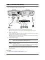
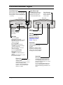
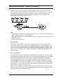
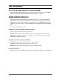
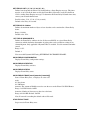
Step 1: Connect the Cables
Leave your computer on when connecting the cables.
Front of device
VHSI Port
Back of device
Ethernet Port
VHSI
Light
VHSI
cable
Blue
Ethernet
cable
(straightthrough)
Ethernet
Lights
Power
Light
Power
Ethernet Hub
Power
adapter
To modem or
leased line
1.
Connect the power adapter. The Power indicator light should turn green.
Note: For more information on indicator lights, see Ports and Indicator Lights on page 29.
2.
Connect your VHSI Cable.
Connect the appropriate end of the cable to the VHSI port of the Eicon 1530, and connect
the other end to your modem or leased line connector.
Note: VHSI cables are not included with your Eicon 1530. Cables can be ordered from Eicon Networks,
or you can build your own (see the User’s Guide).
3.
Connect the Ethernet cable.
LAN
Plug one end of the included blue Ethernet cable into your network hub, then
plug the other end into the Eicon 1530’s Ethernet port.
Note: To connect the Eicon 1530 to a single computer, a crossover cable (sold
Single
Computer separately) is required.
Plug one end of your crossover cable into the Ethernet port on your computer,
then plug the other end into the Eicon 1530’s Ethernet port.
The green light at the top left corner of the Ethernet port should turn on when the cable is
connected properly.
What’s Next?
See Step 2: Verify Computer TCP/IP Settings on page 14.
Setup
13
Step 2: Verify Computer TCP/IP Settings
The Eicon 1530 settings are changed via a series of web pages that reside on the Eicon 1530
itself. However, to access these pages, your TCP/IP settings must be configured appropriately,
as described below.
IP Address Recommendations
• Set your Ethernet card to acquire its IP address dynamically if:
– You are connecting the Eicon 1530 to a single computer.
– You are installing on a LAN and wish to use the Eicon 1530 as your DHCP server.
The Eicon 1530, which has a built-in DHCP server, will assign an IP address to your
computer’s Ethernet card. Most network cards are configured this way by default.
• Set the IP address of your Ethernet card to the address 192.168.1.2 and subnet mask to
255.255.255.0, with the default gateway left blank, if:
– Your LAN already has an existing DHCP server.
– Your LAN uses static IP addressing.
By changing your IP address and subnet mask to these values, you are ensuring that your
computer is on the same subnet as the Eicon 1530, whose IP address is 192.168.1.1 by default.
Later you will change the Eicon 1530’s IP address to one more appropriate for your LAN.
Note: For information on changing TCP/IP settings, see Changing TCP/IP Settings to DHCP, or consult
the documentation included with your operating system.
LAN Setup Notes
• Due to the wide range of networking equipment and topologies that are in use worldwide,
your configuration needs may fall outside the instructions presented here. Contact your
network administrator or other support person to help you with the installation.
• The Eicon 1530’s internal DHCP server is enabled by default. However, if the Eicon 1530
detects the presence of the an existing DHCP server, the Eicon 1530 will disable its own DHCP
server automatically. To re-enable the Eicon 1530 DHCP server, remove the other server from
the LAN and press the reset button on the Eicon 1530.
Restarting your computer
For some operating systems, you must restart your computer after changing TCP/IP settings. If
you are using the Eicon 1530 as a DHCP server on your LAN, or if you have connected the
Eicon 1530 to a single computer, restarting will force your computer to acquire a new IP
address.
If you are using Windows, you can do the following:
• Windows 95/98/Me: Click ‘Start’, ‘Run’, type ‘winipcfg’, and click ‘OK’. Click ‘Renew All’.
• Windows NT/2000/XP: Launch a command prompt, type ‘ipconfig /release’ and press Enter,
then ‘ipconfig /renew’ and press Enter.
What’s Next?
See Step 3: Log in to the Eicon 1530 on page 15.
Setup
14
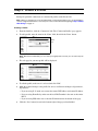
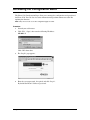
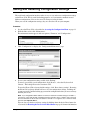
Step 3: Log in to the Eicon 1530
Whenever you wish to change settings on the Eicon 1530, you must first log in, as shown below.
1.
Launch your web browser and click ‘File’, ‘Open’.
2.
Enter 192.168.1.1 as the web page to open.
3.
Click ‘OK’. You should see the ‘Log in’ page.
Note: If you do not see the ‘Log in’ page, see Troubleshooting on the following page.
4.
Click the ‘Log in’ button.
Note: By default there is no password.
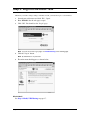
5.
The main menu should appear, as shown below.
What’s Next?
See Step 4: Modify VHSI Settings on page 17.
Setup
15
Troubleshooting
If you cannot access the ‘Log in’ page:
• Verify that the Ethernet cable is connected properly. The green light at the top left of the
Ethernet port should be on (see Ports and Indicator Lights on page 29 for more information).
• Verify that your computer’s TCP/IP settings are configured according to your situation. As
the Eicon 1530’s default IP address is 192.168.1.1, you will not be able to access the web
pages unless your computer is on the same subnet (assigned an IP address that starts with
192.168.1 and is using the same subnet mask).
• Verify that your web browser is configured to use the LAN and not a dial-up connection, and
that your browser is not set to use a proxy server. See Adjusting Browser Settings (below)
for instructions on how to do this.
If you cannot access the ‘Log in’ page over a LAN:
• Verify that your computer is on the same physical segment as the Eicon 1530.
• Verify that the Eicon 1530 is the only device on your LAN using the address 192.168.1.1. To
see if this is the case, remove the Eicon 1530 from the LAN, then PING the address
192.168.1.1. If you receive a reply, a device on the LAN already has this address. In this case,
the best solution is to connect the Eicon 1530 to a single computer as described below.
• In general, if you cannot access the ‘Log in’ page, connect the Eicon 1530 to a single computer
for configuration purposes. Later on you can reconnect the Eicon 1530 to the LAN. Note that
a crossover cable (sold separately) is required; the blue cable included with your package will
not work when connecting directly to a single computer.
Adjusting Browser Settings
If you are not able to access the configuration pages, verify your browser settings as described
below. Note that the steps may vary slightly depending on the browser version used.
• Internet Explorer version 5 or later:
– From the ‘Tools’ menu, select ‘Internet Options’, click the ‘Connections’ tab, then click
‘Setup’.
– Select the option ‘I want to set up my Internet connection manually’, then click ‘Next’.
– Select ‘I want to connect through a local area network’, then click ‘Next’.
– Clear all proxy options, then click ‘Next’.
– Clear the option ‘Connect to the Internet immediately’, then click ‘Finish’.
• Internet Explorer previous to version 5:
– From the ‘View’ menu, select ‘Internet Options’, then click the ‘Connection’ tab.
– Verify that ‘Connect to the internet using a local area network’ is enabled.
– Verify that the ‘Proxy Server’ option is disabled.
• Netscape Navigator (do one of the following):
– Under Options, click ‘Network Preferences’, then ‘Proxies’. Verify that the ‘No Proxies’
option is selected.
– Under the ‘Edit’ menu, click ‘Preferences’, ‘Advanced’, then ‘Proxies’. Verify that the
‘Direct Connection to the Internet’ is enabled.
Once finished making changes, click ‘OK’, then retry accessing the web configuration pages.
Setup
16
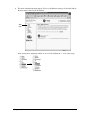
Step 4: Modify VHSI Settings
Once you have logged into the Eicon 1530 web interface, the first setting you should verify is
the choice of protocol for the VHSI port (set to ‘X.25’ by default). The protocol should be
selected first because all profile settings (which define particular connections) are deleted when
the protocol is changed.
About the Web Interface
The Eicon 1530 settings are changed via web pages that reside on the Eicon 1530 itself.
• When making changes using the web interface, make sure to click the ‘Save’ button on
each page. The ‘Save’ button is located at the bottom right of each web page. If you move to
another page without saving, your changes will not be saved to the device.
‘Save’
button
Once saved, the new settings will not take effect until you reset the device. It is not necessary
to do a reset until you have completed all the steps in this quickstart.
• The ‘Reset Form’ button, located at the bottom left of each page, reverts all settings in the
current page back to the original values when the page was opened.
‘Reset
form’
button
• Clicking a setting name displays context-sensitive help.
• Once you have finished making changes to all settings, you must click the ‘Reset’ button,
located at the top of the browser window, for the settings to take effect.
Setup
17
Choosing a VHSI Protocol
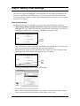
1.
From the Link List (the menu at the left of the screen), click on the small ‘+’ next to ‘VHSI
Port’ to expand the VHSI Port group, then click the ‘Protocol’ link.
‘Protocol’
link
2.
From the ‘Protocol’ drop-down menu, select a protocol.
‘Protocol’
drop-down
menu
3.
Click the ‘Save’ button, located at the bottom right of the web page, when finished.
Note: If you do not click ‘Save’, the changes will be lost when you move to another page.
Modifying Other VHSI Settings
After choosing a protocol, make changes to your VHSI settings, if required. The settings
presented will depend on the protocol chosen.
Note: You can bring up context-sensitive help for each setting by clicking on the setting name. Also, when
making changes, ensure that the new settings are consistent with those of your network provider.
• If the protocol is set to X.25 or Frame Relay:
– Verify all settings as presented on the Protocol page (this should be the current page) and
click ‘Save’.
– If required to make changes to HDLC or Static DLCI settings, click the ‘HDLC’ (for X.25)
or ‘Static DLCI’ (for Frame Relay) link (located at the top of the Protocol page), make any
required changes, then click ‘Save’.
• If the VHSI port is connected to a dial-up line, click ‘Dialer’ in the Link List. Make any
required changes, then click ‘Save’.
• Click ‘VHSI Port’ in the Link List. Make any required changes, then click ‘Save’.
What’s Next?
See Step 5: Create a Profile on page 19.
Setup
18
Step 5: Create a Profile
Settings for particular connections are contained in profiles on the Eicon 1530.
Note: When you change protocols for the VHSI interface, all profile information is lost. To avoid having to
re-enter configuration information, choose the protocol first, as described at the beginning in Step 4: Modify
VHSI Settings on page 17.
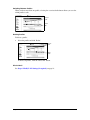
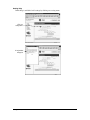
Creating a Profile
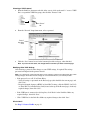
1.
From the Link List, click the ‘Connection’ link. The ‘Connection Profiles’ page appears.
2.
To add a profile, enter the name in the ‘Name’ field, then click the ‘Done’ button.
‘Name’
field
Note: With X.25 or Frame Relay, you can create up to eight profiles. For PPP, you can create only one
profile.
3.
The web page for your new profile will be displayed.
4.
To edit the profile, make sure it is selected and click ‘Edit”.
5.
Make the required changes to the profile. Be sure to scroll down and inspect all parameters.
In particular:
• If you are using X.25, make sure to enter the remote DTE address and remote IP address.
• If you are using Frame Relay, make sure the local DLCI number is the same as the remote
DLCI.
• If you are using PPP, make sure to enter the IP information at the bottom of the page.
6.
Setup
Click the ‘Save’ button (located at the bottom right of the page) when finished.
19
Switching Between Profiles
When you have more than one profile, selecting the associated radio button allows you to select
which profile to edit.
1. Select
Profile
2. Click
‘Edit”.
Deleting Profiles
To delete a profile:
1.
Select the profile and click ‘Delete’.
1. Select
profile
2. Click
‘Delete’.
To delete all profiles, click the ‘Delete All’ button.
What’s Next?
See Step 6: Modify LAN Settings (if required) on page 21.
Setup
20
Step 6: Modify LAN Settings (if required)
The following changes may be required if you are connecting the Eicon 1530 to a LAN.
Change Device IP Address
The Eicon 1530’s default IP address of 192.168.1.1 may or may not be suitable for your LAN.
If you are unsure as to whether or not the IP address should be changed, consult your support
personnel. Some guidelines are given below.
• Eicon 1530 as DHCP server: You do not have to change the Eicon 1530’s IP address.
• Existing DHCP server: You must change the Eicon 1530’s IP address so it is outside the
range of dynamically assigned ones, or you must reserve the address.
• Computers with fixed IP addresses: You must change the Eicon 1530’s IP address so that
it corresponds to what is available on your network.
To change the device IP address:
1.
From the Link List, click ‘LAN’. The Eicon 1530 displays the LAN parameters page.
2.
Modify the ‘IP address’ and ‘Subnet Mask’ settings to addresses appropriate for your LAN.
‘IP address’ and
‘Subnet Mask’
settings
3.
Click the ‘Save’ button.
Disable DHCP
If your LAN has an existing DHCP server, you should disable the Eicon 1530’s DHCP server.
Note: The Eicon 1530 automatically de-activates its own DHCP server if an existing DHCP server is
detected. To re-activate this feature, remove the existing server from the LAN and reset the Eicon 1530.
To disable the DHCP server:
1. In the Link List, click the ‘+’ next to ‘IP’, then click ‘DHCP’ from the submenu.
2. In the ‘DHCP’ page, clear the ‘Enable DHCP’ checkbox.
3. Click the ‘Save’ button.
What’s Next?
See Step 7: Reset the Device on page 22.
Setup
21
Step 7: Reset the Device
For your settings to take effect, you must reset the device by clicking the ‘Reset Device’ button
at the top of the browser window.
‘Reset Device’
button
Notes:
• Normally you are returned to the welcome page after performing a reset. However, if the LAN
IP address has been changed, you will lose contact with the Eicon 1530. If this is the case,
you should receive an error message from your browser after about 45 seconds. To re-establish
contact with the device, open the web configuration interface using the new IP address.
• If you changed the IP address of your computer in order to configure the Eicon 1530, you may
need to return these settings to their original state.
• If you are using the Eicon 1530 as your DHCP server, you may need to restart your computer
in order to acquire a new IP address from the device. If you are using Windows, you can do
the following to acquire a new IP address without restarting:
Windows 95/98/Me: Click ‘Start’, ‘Run’, type ‘winipcfg’, and click ‘Enter’. Click ‘Renew
All’.
Windows NT/2000/XP: Launch a command prompt, type ‘ipconfig /release’ and press Enter,
then ‘ipconfig /renew’ and press Enter.
What’s Next?
See Step 8: Test WAN Access on page 23.
Setup
22
Step 8: Test WAN Access
Once you have made the required changes, test that you have access to the remote device using
your WAN application. You can also ping the remote device to which you are attempting to
connect.
Troubleshooting
If you cannot access the WAN:
• Check your configuration settings (see Step 4: Modify VHSI Settings on page 17). Verify
that your settings are consistent with those of your network provider.
• Verify that your TCP/IP settings are correct for your situation (DHCP client or static IP
address) and that you have restarted your computer. If you cannot access the ‘Log in’ page
again, follow the instructions and suggestions given in Step 3: Log in to the Eicon 1530 on
page 15.
What’s Next?
• If you are using the Eicon 1530 over a LAN, see Adjusting LAN Settings (if required) on
page 24 to verify if you must modify other LAN settings.
• To learn more about your Eicon 1530, see Using your Eicon 1530 on page 28.
Setup
23
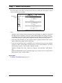
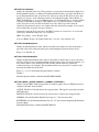
Adjusting LAN Settings (if required)
Depending on your setup, you may have to adjust some of the configuration settings on your
computers or servers in order to communicate with the Eicon 1530. Due to the diversity of
networking equipment and topologies, this section can only cover the most common setups. If
you setup is more complex, contact your network administrator (or other support personnel) to
help with the installation.
Once you make these changes, the computers on your network may need to be restarted in
order to acquire the new settings.
• If your LAN uses static addressing: Set the ‘Default Gateway’ and ‘DNS Server’ settings
of each computer to the address of the Eicon 1530. These settings are normally found in the
TCP/IP settings for your operating system.
• If your LAN has a DHCP server: Configure your DHCP server to return the address of the
Eicon 1530 as the ‘Default Gateway’ and ‘DNS Server’ to all clients.
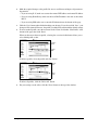
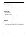
• If your LAN has a router: Most likely, your router is configured as the default gateway for
your computers. In this case, you will need to configure the routing table on your router to
re-direct the appropriate traffic to the Eicon 1530, as well as add a route on the Eicon 1530 to
direct appropriate traffic to the router.
Consider the following example:
Eicon 1530
Traffic from LAN A addressed to LAN B is forwarded by the router to LAN B.
Traffic from LAN B addressed to the external network needs to be forwarded by the router to
the Eicon 1530. This requires you to configure a route on the router.
Traffic from the external network to LAN B needs to be forwarded to the router. This requires
you to configure a route on the Eicon 1530. No route is needed for traffic to LAN A.
Setup
24
Changing TCP/IP Settings to DHCP
For most connection scenarios, your computer must have TCP/IP configured to act as a DHCP
client. This allows your computer to dynamically acquire its IP address and other settings from
the Eicon 1530.
Note: If you do not want to use the Eicon 1530’s DHCP feature, you must change the IP address of your
computer to 192.168.1.2, or 192.168.1.3, etc., as the default IP address is 192.168.1.1.
The following procedures describe how to set your TCP/IP settings for Windows 95,
Windows 98, Windows NT 4.0, Windows 2000, and Windows XP. For other platforms, consult
the documentation for your operating system.
• TCP/IP Settings for Windows 95/98/Me ............................................................ 25
• TCP/IP Settings for Windows NT 4.0................................................................. 26
• TCP/IP Settings for Windows 2000/XP.............................................................. 26
TCP/IP Settings for Windows 95/98/Me
The following procedure describes how to verify and install TCP/IP on Windows 95,
Windows 98, or Windows Me. Note that if you have more than one Ethernet adapter installed
on your system, you must only change the settings for the adapter used by the Eicon 1530.
1.
Click ‘Start’, ‘Settings’, ‘Control Panel’.
2.
Double-click the ‘Network’ icon. The ‘Network’ dialog box appears. By default, the
‘Configuration’ tab is displayed.
3.
If ‘TCP/IP’ is not listed for your network adapter in the ‘Components’ list, you must add it,
as described below.
•
•
•
•
•
•
Click ‘Add’. The ‘Select Network Component Type’ dialog box appears.
Select ‘Protocol’, then click ‘Add’. The ‘Select Network Protocol’ window appears.
In the ‘Manufacturer’ box, select ‘Microsoft’.
In ‘Network Protocols’, select ‘TCP/IP’.
Click ‘OK’. Once installation is complete, you are returned to the Network window.
Do not click the ‘OK’ button yet; next you will verify your TCP/IP settings.
4.
In the list of components, select ‘TCP/IP’ for your network card, then click ‘Properties’. The
‘TCP/IP Properties’ dialog box appears.
5.
Click the ‘IP Address’ tab and select ‘Obtain an IP address automatically’. This defines your
machine as a DHCP client.
6.
Click the ‘WINS Configuration’ tab and select ‘Use DHCP for WINS Resolution’.
7.
Click the ‘Gateway’ tab and remove all existing gateways.
8.
Click the ‘DNS Configuration’ tab and select ‘Disable DNS.’ This instructs your computer
to obtain DNS server information via DHCP.
9.
Click ‘OK’, then click ‘OK’ again.
Note: You may be asked to insert your original Windows installation CD-ROM.
10.
Setup
Click ‘Yes’ when prompted to restart your system.
25
TCP/IP Settings for Windows NT 4.0
The following procedure describes how to install TCP/IP on Windows NT 4.0. Note that if you
have more than one Ethernet adapter installed on your system, you must only change the
settings for the adapter used by the Eicon 1530.
1.
Click ‘Start’, ‘Settings’, ‘Control Panel’.
2.
Double-click the ‘Network’ icon. The Network dialog box appears.
3.
Click the ‘Protocols’ tab.
4.
If ‘TCP/IP’ is not listed, you must install it, as described below.
•
•
•
•
From the ‘Protocols’ tab, click ‘Add’.
Select ‘TCP/IP protocol’ as your network protocol, then click ‘OK’.
Click ‘Yes’ to use DHCP.
When prompted, insert the original Windows NT installation CD and enter d:\i386 (where
d: is the drive letter of your CD drive), and click ‘Continue’.
• Do not click the ‘OK’ button yet; next you will verify your TCP/IP settings.
5.
Click the ‘Protocols’ tab.
6.
Select ‘TCP/IP protocol’, then click ‘Properties’.
7.
Select ‘Obtain an IP address from a DHCP server’.
8.
Click the ‘DNS’ tab. Delete any DNS addresses are configured.
9.
Click ‘OK’.
10.
Restart your computer if requested to do so.
TCP/IP Settings for Windows 2000/XP
Windows 2000/XP automatically created a network adapter profile (named ‘Local Area
Connection’ by default) when the adapter was installed. Note that if you have more than one
Ethernet adapter installed on your system, you must only change the settings for the adapter
used by the Eicon 1530.
1.
Click ‘Start’, ‘Settings’ then ‘Network and Dial-up Connections’ (‘Network Connections’
for Windows XP).
2.
In the Network and Dial-up Connections (Network Connections for Windows XP),
right-click the appropriate adapter entry and click ‘Properties’. The properties window for
this adapter is displayed.
3.
Select ‘Internet Protocol (TCP/IP)’, then click ‘Properties’.
4.
The settings should be ‘Obtain an IP address automatically’ and ‘Obtain DNS server
automatically’.
5.
Click ‘OK’, then ‘OK’ again, then click ‘Close’.
6.
Restart your computer if requested to do so.
Setup
26
Technical Support
To obtain technical support for Eicon Networks products, visit our web site at:
http://www.eicon.com/support/
For the latest information on the Eicon 1530, visit:
http://www.eicon.com/wan1530/
For customer service, contact your Eicon Networks supplier.
Setup
27
Using your Eicon 1530
Ports and Indicator Lights ....................................................................................... 29
Resetting the Device via the Reset Button .............................................................. 30
Accessing the Configuration Menu ......................................................................... 31
Upgrading Firmware via a Web Browser............................................................... 35
Saving and Resetting Configuration Settings ......................................................... 36
Changing the VHSI Port Protocol ........................................................................... 37
Creating and Editing Profiles .................................................................................. 39
28
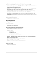
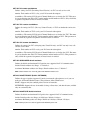
Ports and Indicator Lights
Green Ethernet Light
Amber Ethernet Light
ON: The Ethernet cable is connected properly.
OFF: The Ethernet cable is not connected, or
the wrong cable is connected (straight-through
or crossover).
FLASHING: Data is being sent or
received via the Ethernet cable.
OFF: Data is not being sent or
received via the Ethernet cable.
Front of Unit
AUX Port
Used for connecting your
Eicon 1530 to the wide
area network.
Auxiliary port (currently not used).
If you are using X.25:
ON: The X.25 layer is ready.
FLASHING: The X.25 layer is not ready.
OFF: The X.25 port is closed or the
cable is disconnected.
If you are using PPP:
ON: The PPP layer is connected.
FLASHING: The PPP layer is trying to
connect to a remote site.
OFF: The PPP layer is closed or the
cable is disconnected.
If you are using Frame Relay:
ON: The Frame Relay layer is
connected.
FLASHING: The Frame Relay layer is
opening.
OFF: The Frame Relay layer is closed or
the cable is disconnected.
AUX Light
Shows the status of the
AUX port (currently unused).
Also lights up to indicate the
status of a factory reset (see
Reset Settings to Factory
Defaults on page 30).
Reset Button
Used for resetting the Eicon 1530.
Pressing this button once resets
the device.
Warning! All configuration settings
are lost if you hold down the Reset
button for 15 seconds, which returns
all settings back to factory defaults.
Ethernet Port
Used for connecting to the Eicon 1530 to a
computer or LAN.
A straight-through cable (the blue cable) is
used for connecting to a LAN.
A crossover cable (sold separately) is
required to connect the Ethernet port
directly to a computer.
Using your Eicon 1530
Used for connecting
the Eicon 1530 to an
electrical outlet.
Back of Unit
VHSI Port
VHSI Light
Power Connector
Power Light
ON: Power adapter is properly connected.
FLASHING: Device is in boot mode. If you
are not upgrading firmware while in boot
mode, press the Reset button once to return
the device to normal.
If you are upgrading firmware while in boot
mode, do not press Reset for at least one
minute after transferring the firmware to the
device.
29
Resetting the Device via the Reset Button
The Reset button for the Eicon 1530 is shown below.
Front of Device
Back of Device
Reset
button
Normal Reset
If you press the Reset button once quickly, you will do a ‘normal’ reset. This reboots the
device, and your settings are left intact.
You can also do a normal reset using the ‘Reset’ button at the top of the browser window when
you are using the web interface.
Reset Settings to Factory Defaults
Warning: Resetting to factory defaults erases all configuration settings.
To reset to factory defaults, hold down the ‘Reset’ button for at least 15 seconds. The AUX light
will turn on, then will go off after 15 seconds, indicating the reset is complete.
Note: This procedure will return the default IP address of the Eicon 1530 to 192.168.1.1. If you changed
the IP address of the Eicon 1530 from this default setting, you will need to use the default IP address
192.168.1.1 to access the configuration menu.
You can also reset to factory defaults using the Web-based configuration interface (see Saving
and Resetting Configuration Settings on page 36) as well as the Reset Factory command (see
General Commands on page 108 for more information).
Entering Boot Monitor Mode
If you hold down the reset button for five seconds and less than 15 seconds, you will enter Boot
Monitor mode, which is used for troubleshooting purposes only. Press the ‘Reset’ button once
more to return the device back to normal operation.
Using your Eicon 1530
30
Accessing the Configuration Menu
The Eicon 1530 Configuration Pages allow you to manage the configuration and operation of
the Eicon 1530. You can also view status information and perform maintenance tasks like
updating the firmware.
Note: Only one user can access the configuration pages at a time.
Procedure
1.
Launch your web browser.
2.
Click ‘File’, ‘Open’, then enter the following IP address:
192.168.1.1
Click ‘OK’ when done.
3.
The ‘Log In’ page appears.
4.
Enter the system password, if required, and click ‘Log in’.
By default the Eicon 1530 has no password.
Using your Eicon 1530
31
5.
The main configuration menu appears. To access the different settings, click on the links in
the main menu, at the left of the window.
Main
menu
Some settings have subgroups, which are accessed by clicking the ‘+’ next to the group.
Using your Eicon 1530
32
Saving configuration settings and resetting the device
Most pages in the configuration interface have a ‘Save’ button. When you click this button,
your changes are saved to the Eicon 1530.
‘Save’ button
However, for the changes to take effect, you must reset the Eicon 1530. You can do this by
clicking the ‘Reset Device’ button on the main menu, or you can press the reset button on the
device itself (see Resetting the Device via the Reset Button on page 30 for more
information).
‘Reset Device’
button
Using your Eicon 1530
33
Getting Help
Online help is available for all settings by clicking on a setting name.
Click on a
setting name.
A help window
will appear.
Using your Eicon 1530
34
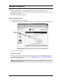
Upgrading Firmware via a Web Browser
Eicon Networks posts the latest Eicon 1530 firmware on its web site. You can automatically
update your Eicon 1530 to the latest version using the web configuration interface.
Note: Configuration settings are normally preserved during firmware updates. However, if you wish to make
a backup of your configuration before upgrading, see Saving and Resetting Configuration Settings on
page 36.
Procedure
1.
Log in to the Eicon 1530 as described in Accessing the Configuration Menu on page 31.
2.
From the main menu, click ‘Maintenance’.
The maintenance menu appears with two options, ‘Firmware’ and ‘Configuration’.
3.
Click ‘Firmware’ to display the ‘Firmware Maintenance’ page.
4.
To save a copy of the Eicon 1530’s current firmware to disk, click ‘Backup’. This is done in
case you encounter problems installing or using the new firmware.
To upgrade the firmware, click the ‘Browse’ button, then select the new firmware file. When
complete, the Eicon 1530 is automatically reset to activate the new firmware.
Using your Eicon 1530
35
Saving and Resetting Configuration Settings
The web-based configuration interface makes it easy to save and restore configuration settings
on the Eicon 1530. This is useful for backup purposes, or if you intend to maintain several
different configurations. You can also reset all settings to factory defaults.
When you save the configuration settings, they are stored in a file on your computer.
Procedure
1.
Log in to the Eicon 1530 as described in Accessing the Configuration Menu on page 31.
2.
From the links at left, click ‘Maintenance’.
The maintenance menu appears with two options, ‘Firmware’ and ‘Configuration’.
3.
Click ‘Configuration’ to display the ‘Configuration Maintenance’ page.
4.
To save your configuration settings to disk, click ‘Backup’.
To restore a previously-saved configuration, click ‘Browse’, select the file, then click
‘Restore’. The backup file uses the extension .CFG.
To reset the Eicon 1530 to factory default settings, click ‘Reset factory settings’. Resetting
the Eicon 1530 to factory defaults will erase all your configuration settings, including the
system password. Consider backing up your current configuration before you reset to factory
defaults, just in case.
Note: If you changed the LAN IP address of the Eicon 1530 from its default setting of 192.168.1.1,
you will lose contact with the web configuration interface after the reset is complete. This is because
the reset will return the Eicon 1530 to its default of 192.168.1.1. To regain access to the Eicon 1530,
open the URL http://192.168.1.1.
You can also reset the box to factory settings by holding down the device Reset button for
15 seconds. See Resetting the Device via the Reset Button on page 30 for more information.
Using your Eicon 1530
36
Changing the VHSI Port Protocol
The Eicon 1530 uses profiles to make individual connections. However, the connection profiles
depend on the protocol chosen for the VHSI port. When you change the VHSI port protocol, all
profiles associated with that protocol are erased. Therefore, it is very important to select the
VHSI port protocol first, before creating or modifying connection profiles.
If you sometimes need to use different VHSI port protocols, use the configuration backup and
restore feature as described in Saving and Resetting Configuration Settings on page 36.
Procedure
1.
Log in to the Eicon 1530 as described in Accessing the Configuration Menu on page 31.
2.
From the main menu, click ‘Protocol’.
Note: The ‘Protocol’ link is part of the VHSI Port group of protocols. If you do not see ‘Protocol’, click
on the small ‘+’ next to ‘VHSI Port’ to expand the VHSI Port subgroup.
3.
The ‘Protocol’ page appears. By default, the protocol is set to X.25.
‘Protocol’
setting
Using your Eicon 1530
37
4.
To change the protocol setting, select a new protocol from the drop-down menu.
In the following example, the protocol was changed from ‘X.25’ to ‘PPP’.
‘Protocol’ is
now set to
PPP
Note: The ‘Protocol’ page may or may not contain general protocol settings, depending on the protocol
chosen. For example, when the protocol is set to X.25, the protocol page lists several parameters that
can be modified. But when the protocol is set to PPP, no parameters are available.
5.
Click the ‘Save’ button to save this setting. You may have to scroll down in order to locate
the button.
If you change your mind and do not want to save your changes, click on any other link (such
as the ‘Home’ link). In doing so, your choice for protocol will be ignored.
Note: Once you click ‘Save’, your connection profile settings are erased. To save your configuration
information before changing the protocol, see Saving and Resetting Configuration Settings on
page 36.
6.
For your settings to take effect, click the ‘Reset’ button at the top of the window. However,
you may wish to modify other VHSI settings first, as well as create connection profiles (see
Creating and Editing Profiles on page 39 for more information).
Using your Eicon 1530
38
Creating and Editing Profiles
Settings for particular connections are contained in profiles on the Eicon 1530. However, when
you change protocols for the VHSI interface, all profile information is lost. To avoid having to
re-enter configuration information, choose the protocol first, as described in Changing the
VHSI Port Protocol on page 37.
Once your protocol is configured properly, you need to create connection profiles. The
following procedure illustrates how profiles are created and modified when the protocol is set
to X.25. The procedure is the same for other protocols.
Certain protocols allow for more than one connection profile. For example, if you have set the
VHSI interface to the ‘X.25’ protocol, you have the option of creating up to eight profiles. For
‘PPP’ however, you can only create one profile.
Procedure
1.
Log in to the Eicon 1530 as described in Accessing the Configuration Menu on page 31.
2.
From the Link List, click the ‘Connection’ link. The ‘Connection Profiles’ page appears.
3.
To add a profile, enter the name in the ‘Name’ field, then click the ‘Done’ button.
‘Name’
field
Note: With X.25 or Frame Relay, you can create up to eight profiles. For PPP, you can create only one
profile.
4.
The web page for your new profile will be displayed.
5.
To edit the profile, make sure it is selected and click ‘Edit”.
Using your Eicon 1530
39
6.
Make the required changes to the profile. Be sure to scroll down and inspect all parameters.
In particular:
• If you are using X.25, make sure to enter the remote DTE address and remote IP address.
• If you are using Frame Relay, make sure the local DLCI number is the same as the remote
DLCI.
• If you are using PPP, make sure to enter the IP information at the bottom of the page.
7.
Click the ‘Save’ button when finished making your changes. If you do not click ‘Save’, your
changes will be ignored. However, the profile you added will remain with the default settings.
8.
To create another profile, enter the new name in the ‘Name’ field under ‘New Profile’ at the
bottom of the page, then click ‘Done’.
When you have more than one profile, selecting the associated radio button allows you to
select which profile to edit.
1. Select
Profile
2. Click
‘Edit”.
To delete a profile, select the profile and click ‘Delete’.
1. Select
profile
2. Click
‘Delete’.
To delete all profiles, click the ‘Delete All’ button.
9.
For your settings to take effect, click the ‘Reset’ button at the top of the window.
Using your Eicon 1530
40
Security
Overview .................................................................................................................... 42
Security Features Summary..................................................................................... 43
System Password ....................................................................................................... 44
Automatic Log Out ................................................................................................... 45
Network Address Translation (NAT) ...................................................................... 46
Remote Management ................................................................................................ 49
Authentication (PPP only)........................................................................................ 51
Manual Dialing.......................................................................................................... 52
Custom Security Features using IP Filters ............................................................. 53
41
Overview
Connecting your computers to an external network creates a wide range of benefits, but also
exposes your computers to certain risks. To safeguard your data and systems, the Eicon 1530
provides a comprehensive range of security features. This section explains how to use and
configure each feature for optimal protection of your systems.
Security
42
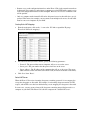
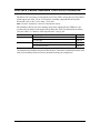
Security Features Summary
This table lists all security features offered by the Eicon 1530, and their default settings.
Feature
Default
Description
System password
None
Restricts access to the Eicon 1530 configuration interfaces.
Automatic log
out
Active
Automatically terminates idle configuration sessions.
Network address
translation (NAT)
Disabled
NAT hides the addresses of the computers on the internal
Ethernet LAN from the external network.
Remote
management
Active
Permits remote systems to log on to the Eicon 1530 web
Call
authentication
(PPP only)
Available
Lets you authenticate an incoming connection, or provide
authentication when making a connection.
Manual dialing
Disabled
Lets you manually control when the connection is
established.
Custom security
using IP filters
None
Allows you to filter specific IP datagrams for security
reasons.
Command Line
Interface
Available
The Command Line Interface allows you to change
settings via text commands.
configuration interface.
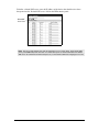
The following table lists the security features that can be applied to restrict access to the
Eicon 1530 configuration interfaces.
Source system
Connection
Security features that apply
Remote computer external
network
•
•
•
•
•
Local computer
• System password
• Automatic log out
• Custom security using IP filter
Security
Ethernet
System password
Automatic log out
Remote Management
Call authentication
Custom security using IP filters
43
System Password
The Eicon 1530 provides a system password that restricts access to the web-based
configuration interface and the CLI. This ensures that configuration changes can only be made
by authorized personnel.
By default, no password is defined.
Setting a System Password
1.
From the Link List, click ‘System’.
2.
Enter the new system password in the ‘Login Password’ and ‘Repeat Login Password’ fields.
Password
fields
3.
Click ‘Save’ then ‘Reset’.
Forgot your Password?
If you have forgotten your password, the only way gain access to the configuration pages is to
reset the Eicon 1530 to its factory defaults. See Resetting the Device via the Reset Button on
page 30 for more information.
Note: Resetting the device also returns all configuration settings, including username and password
information, to factory defaults.
Security
44
Automatic Log Out
The Eicon 1530 applies an automatic timeout to configuration sessions. When a configuration
session is idle for more than the timeout value, the Eicon 1530 automatically logs the user out.
This reduces the risk of unauthorized persons taking advantage of a logged-in computer that
has been left unattended.
The timeout values, which are not configurable, are as follows:
• Web interface: 30 minutes.
• Telnet session: 2 minutes.
Note: Changes that have not been saved are lost when the configuration session is terminated.
Security
45
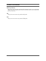
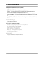
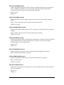
Network Address Translation (NAT)
The Eicon 1530 uses network address translation (NAT) to ‘hide’ the local LAN from all
external resources. The benefits of this are the ability for all connected computers to access the
external network using one user account, defined on the device itself. For example, when
communicating with the Internet, the four computers in the following diagram share the
dynamically assigned address ‘222.182.22.39’.
Notes
• NAT operates transparently, translating internal addresses to a single external one for all data
traffic. NAT has no effect on total throughput.
• Most applications will work with NAT. However, some programs may not work well or at all
with NAT enabled.
• NAT is disabled by default.
Security benefits
An additional benefit of NAT is increased network security. Like a firewall, NAT restricts
access to the computers that reside on the local LAN. By default, no computer on the internal
LAN is visible to the external. Computers on the internal network cannot act as FTP or web
servers, nor can they share their drives using Windows Network Neighborhood. These security
features can be weakened if you use NAT static mappings (see NAT static mappings on the
following page).
NAT static mappings
With NAT enabled, computers outside of the internal LAN do not have access (are not visible)
to any computers on the internal LAN. If you need a computer on the internal LAN to be visible
to the external network, the Eicon 1530 provides a solution through NAT static mappings.
NAT static mappings allow you to permit specific computers on the internal LAN to receive
certain incoming network traffic. For example, you could designate a computer to receive all
incoming HTTP traffic, allowing it to function as a web server. However, the actual IP address
of this computer is still hidden by NAT. Therefore, remote users must specify the address of the
Eicon 1530 to gain access to the web server.
When you create a NAT static mapping, the Eicon 1530 routes all traffic for the protocol you
specify to the designated computer. This includes traffic normally handled by the Eicon 1530
itself. This leads to the following restrictions:
Security
46
• Remote access to the configuration interfaces on the Eicon 1530 via the external network can
be disrupted. For example, if you designate a computer to receive HTTP traffic, remote access
to the web configuration interface will be disrupted. However, local access via Ethernet will
still be possible.
• Only one computer on the internal LAN can be designated to receive the traffic for a specific
protocol. This means, for example, you can cannot create multiple web servers; all web traffic
must be sent to one computer on your LAN.
Creating Static NAT Mappings
1.
From the main menu, click on the ‘+’ next to the ‘IP’ link to expand the IP group.
Then click ‘NAT static mappings’.
2.
For each server that you want to define, specify the following parameters:
• ‘Protocol’: The protocol that remote computers will use to access the server.
• ‘Server port’: The port number that the protocol will use on the server.
• ‘Server address’: The IP address of the computer that will act as the server. The server
address must be on the same LAN as the Eicon 1530 (or must be reachable via the LAN).
3.
Click ‘Save’ then ‘Reset’.
Default NAT Server
When the Eicon 1530 receives incoming datagrams containing protocols it is not supposed to
accept, the datagrams are discarded. For example, if an incoming datagram contains an FTP
request, and no FTP server has been defined using a static mapping, the datagram is discarded.
In some cases, you may want to forward all datagrams containing unspecified protocols to a
computer on your LAN. The Eicon 1530 calls this computer the ‘default NAT server’.
Security
47
To define a default NAT server, enter the IP address of the device that should receive these
datagrams into the ‘Default NAT server’ field on the IP Parameters panel.
‘Default NAT
Server’ field
Note: The Eicon 1530 handles traffic with the following protocols: HTTP, Telnet, TFTP, ECHO (UDP
port 7), and SNMP. Only traffic that does not contain these protocols will be forwarded to the default
NAT server. To forward the aformentioned protocols you must define a NAT static mapping for each one.
Security
48
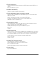
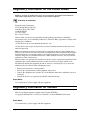
Remote Management
By default, the Eicon 1530 allows remote devices to access its configuration interfaces via the
external network. This feature can be disabled; however, this does not affect traffic on the local
LAN created by the Eicon 1530. If the local LAN is connected to other networks, these
computers will continue to have access to the Eicon 1530, even if remote management is
disabled. Consider the following topology:
In the above example, all computers on the two LANs have access to the Eicon 1530
configuration interfaces. However, remote computer A is blocked as it must go through the
external network to access the Eicon 1530.
Note: Remote security is implemented using IP filtering. In the web interface, expand the ‘IP’ section
and click ‘Filters’.
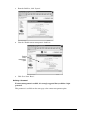
Disabling Remote Management
To disable remote management:
Security
49
1.
From the Link List, click ‘System’.
2.
Clear the ‘Enable remote management’ check box.
‘Enable
remote
management’
option
3.
Click ‘Save’ then ‘Reset’.
Defining a Password
If remote management is enabled, it is strongly suggested that you define a login
password.
This parameter is available on the same page as the remote management option.
Security
50
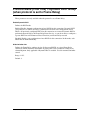
Authentication (PPP only)
Authentication works through the exchange of usernames and passwords. This process can be
one-way (either the caller or callee gets validated) or two-way (both sides validate each other).
Generally, authentication is one-way, with the incoming connection being validated. For
example, when the Eicon 1530 connects to a device on the external network, the Eicon 1530 is
authenticated by the remote device, i.e., the Eicon 1530 must supply a username and password
to log on.
To successfully use authentication, it is important that both devices are configured to support
the same authentication options.
Setting up Call Authentication
1.
From the Link List, click ‘Connection’.
2.
Scroll down to the ‘Authentication’ section of the page.
Note: This section will only appear if the protocol is set to PPP and you have created a profile.
3.
Specify the ‘Local username’ and ‘Local password’. These values will be sent to the remote
site during the authentication process.
Note: Usernames and passwords are case-sensitive.
4.
If passwords must be encrypted, enable the ‘Always use encrypted password’ option.
5.
If required, enable the ‘Always authenticate remote’ option, then enter the ‘Remote
username’ and ‘Remote password’. The remote device must supply its own username and
password in order for the connection to be completed.
6.
Click ‘Save’, then ‘Reset’.
Security
51
Manual Dialing
The Manual Dialing feature lets you manually control when the connection is to be established.
Enabling Manual Dialing
1.
From the Link List, click ‘Connection’.
2.
Scroll down to the ‘IP’ section of the page.
‘Manual
Dialing’
option
3.
Check the ‘Manual Dialing’ option.
4.
Click ‘Save’, then ‘Reset’.
Security
52
Custom Security Features using IP Filters
By using IP filters you can create your own custom security solutions. For example, you can
limit local access to the Eicon 1530 for specific computers, accept incoming traffic only from
certain remote users or networks, or drop incoming or outgoing nuisance traffic.
•
•
•
•
•
How Filtering Works............................................................................................ 53
Defining a New Filter ........................................................................................... 54
‘Edit Filters’ Page Options .................................................................................. 56
Example: Dropping incoming traffic from a specific network ........................ 59
Example: Allowing incoming traffic only from a specific network ................. 60
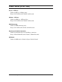
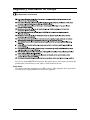
How Filtering Works
Each profile you define for a particular connection has its own set of filters (called the ‘filter
stack’). All data packets, incoming and outgoing, pass through the filter stack of the profile
being used for a particular connection. A filter stack can have up to 8 filters, allowing for
sophisticated results.
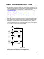
Data cascades through the filter stack as shown in the following diagram. If a packet matches
one of the filters in the stack, the filter action is performed.
Input to filter stack
Are any filters No
active?
Bypass filter stack
Yes
Send all data into filter stack
Filter #1
Apply filter
conditions
Data that matches
Data that does
not match
Filter #2
Apply filter
conditions
Data that matches
Data that does
not match
Filter #8
Apply filter
conditions
Data that matches
Data that does
not match
Action
Forward
Drop
Discard
Action
Forward
Drop
Discard
Action
Forward
Drop
Discard
Discard
Output from filter stack
Note: All incoming and outgoing data passes through the filter stack.
Once any filter is activated, data transfer will be affected.
Security
53
Important Notes on Filters
• Profile information is not retained when the protocol (PPP or X.25) is changed. Since filters
apply to individual profiles, filter information is also lost when the protocol is changed. Be
sure that you have set up the Eicon 1530 with the proper protocol, and that you have created
all the necessary profiles, before creating filters.
• If you create a new profile, then wish to add filters for the profile, you must first reset the
device. Click the ‘Reset Device’ button at the top of the browser window. You will not be able
to create filters for a new profile until the device is reset.
• Unlike other configurations settings, you do not have to reset the Eicon 1530 to make filters
operational. Once you define and enable the filter, then press ‘Save’, as described in the section
Defining a New Filter (below), the filter becomes active. This means you must take special
care in creating filters, as you could filter out your own access to the box accidentally.
Defining a New Filter
Filters become active immediately after they are defined, saved, and enabled.
1.
Start the web configuration interface and log in.
Note: If you have created a new profile since the last time the device was reset, reset the device now
by clicking ‘Reset Device’ at the top of the browser window. You must have at least one profile defined
before you can create a filter.
2.
Click the ‘+’ next to ‘IP’ in the Link List to expand the IP tree.
3.
Click ‘Filters’ to display the ‘Filter Parameters’ page.
As shown in the above screenshot, the Eicon 1530 assigns a default filter automatically. This
filter forwards all packets using any protocol, essentially letting all data pass through
unfiltered.
4.
If you have more than one profile available, select a profile from the drop-down menu (next
to ‘Edit filters for’).
Profile
list
Security
54
5.
To insert a new filter, click the ‘+’ symbol.
‘Plus’
symbol
6.
The ‘Edit Filters’ page appear.
7.
Define the settings for the filter using the drop-down menus and click ‘Done’.
The following diagram shows a quick description of what each field means. For more details
on the available options, see ‘Edit Filters’ Page Options on page 56.
Source /Destination
Action Direction
Address
8.
Location
Protocol
When finished, click the ‘Save’ button.
Note: Two other options, the ‘Select the operation...’ menu and the ‘Do it!’ button, are located at the
bottom of the ‘Edit Filters’ page. These options allow you to delete filters, or copy filters from one profile
or another, and are not used for defining a filter.
Security
55
9.
Once you click ‘Save’, you are returned to the main filter page. The new filter you just defined
is shown in the list. However, the checkbox to the left of the filter definition is empty,
indicating that the filter is not enabled.
The
new
filter
10.
Enable the filter by clicking the box that appears to the right of the ‘Edit’ button.
Checkbox
11.
Click ‘Save’. This makes the filter operational.
Note: Unlike other configurations settings, you do not have to reset the Eicon 1530 to make filters
operational.
‘Edit Filters’ Page Options
Action
• ‘Drop’: Discard data that matches the filter definition.
• ‘Forward’: Send data that matches the filter definition to the filter output.
• ‘Forward if connected’: Send data that matches the filter definition to the filter output, if a
connection is open.
Direction
• ‘incoming’: Data being received by the Eicon 1530 originating from the external network.
• ‘outgoing’: Data being sent by the Eicon 1530 to the external network.
• ‘all’: Both incoming and outgoing.
Security
56
Source / Destination
• ‘from’: Examine the source IP address of the datagram.
• ‘to’: Examine the destination IP address of the datagram.
Location
• ‘the Ethernet LAN’: Sets the filter to match datagrams with network addresses that are the
same as that of the Eicon 1530. By default, this is 192.168.1.0. A mask of 255.255.255.0 is
used to extract the network address.
• ‘the network’: Sets the filter to match datagrams with network addresses that are the same as
that the one you specify. Choosing this option requires that you supply the IP address of a
class C network in the next box. The filter uses a mask of 255.255.255.0 to extract the network
address (class C network mask).
• ‘host’: Sets the filter to match datagrams with IP addresses that are the same as the one you
specify. Choosing this option requires that you supply the IP address of the host computer in
the next box. The filter uses a mask of 255.255.255.255.
• ‘anywhere’: Sets the filter to ignore the source and destination address in the datagram.
Address
• ‘Address’: Only applies if you select the network or the host for location.
Protocol
IP datagrams can carry a wide variety of protocol traffic. The Eicon 1530 lets you filter many of
the most popular protocols. The following descriptions explain some of the options that are
available.
• ‘any’: Applies the filter to any datagram.
• ‘any well known’: Applies the filter to any protocol using TCP or UDP ports in the range 0
to 1023. See RFC 1700 for the complete list of protocols.
• ‘UNIX’: Applies the filter to any protocol using TCP or UDP ports in the range 512 to 1023.
See RFC 1700 for the complete list of protocols.
• ‘TCP’: Many protocols (such as HTTP, FTP, Telnet, News) make use of TCP. If you filter all
TCP traffic you will prevent the use of these protocols. Note that access to the web
configuration interface occurs via HTTP and access to the command line interface (CLI)
occurs via Telnet.
• ‘UDP’: Many protocols (such as SNMP, Time, TFTP, BOOTP) make use of UDP. If you filter
all UDP traffic, you will prevent the use of these protocols.
• ‘FTP’: Applies the filter to all datagrams containing the file transfer protocol.
• ‘Web (HTTP)’: If you filter all HTTP traffic, you may not be able to reach the web
configuration interface. Filtering outgoing HTTP traffic can be used to prevent users from
browsing on the Internet.
• ‘Mail (SMTP)’: Applies the filter to all datagrams containing the mail (SMTP) protocol.
• ‘Mail (POP3)’: Applies the filter to all datagrams containing the mail (POP3) protocol.
• ‘Telnet’: If you filter all Telnet traffic, you will not be able to reach the command line interface
(CLI).
Security
57
• ‘TFTP’: The Eicon 1530 can function as a TFTP server to support uploading and downloading
of configuration files. If you filter TFTP traffic, you will not be able to use this feature.
• ‘DNS’: Domain name system. Filtering DNS datagrams can cause disruptions in the ability
to access remote sites.
The following options are also available: NFS/RPC, News, Time (NTP), BOOTP, SNMP,
ICMP, Ping (ICMP), Ping Reply, ICMP Redir. For a description of these protocols, consult the
appropriate RFC at the site http://www.faqs.org/.
Warning: Be Careful when Creating Filters
The ability to create filters is a very powerful tool. However, it is quite easy to define a filter
that would essentially bar all incoming and outgoing data, including access to the Eicon 1530’s
web or command line interface to change settings.
Please read Default Filters on page 58 before experimenting with filters.
If you find you have accidentally filtered yourself out of access to the Eicon 1530, you must
reset the box to factory defaults by holding down the reset button for 15 seconds. However, you
will lose all configuration information. As a precaution, back up your configuration before
using filters.
Default Filters
When a profile has no filters defined, a default filter is automatically supplied by the
Eicon 1530, as shown below.
Default
filter
The default filter forwards all packets from anywhere. Essentially, all traffic is allowed through
unimpeded. The default filter is always the last filter in the stack and cannot be edited.
Security
58
However, the moment you create one filter, a new default is used that drops all traffic, as shown
below.
New
default
filter
This situation will usually require that you create at least one filter before the last filter. The
new filter would forward legitimate traffic; all other traffic would be dropped by the last filter.
For example, if you wanted to bar all incoming and outgoing web traffic, but allow all other
traffic, the filter stack would resemble the following:
1.
Drop all packets from anywhere using the web protocol.
2.
Forward all packets from anywhere using any protocol.
3.
Drop all packets using any protocol (default last filter).
When a packet goes through the filter stack, the Eicon 1530 would first check if the packet is
using the web protocol. If so, the packet is dropped. If not, the next filter is applied, which
essentially forwards anything. The third filter is never reached, because the second filter
catches all other traffic.
This type of filter stack is called an ‘anything but’ stack, as it lets all traffic through with
specific exceptions. The opposite of this is a ‘nothing but’ stack, which allows packets from
specific networks or protocols, but drops everything else. In this case, the second filter
(‘Forward all packets...’) is not necessary. However, this type of stack is much more restrictive.
See Example: Dropping incoming traffic from a specific network and Example: Allowing
incoming traffic only from a specific network on page 60 for more examples.
Example: Dropping incoming traffic from a specific network
This example defines a filter to make sure that no traffic is accepted from a specific network.
Assume the network has the IP address 213.112.12.0.
Security
59
After creating the first filter, the filter page should look like this:
First filter
Since the Eicon 1530 automatically changed the last filter to one that drops all traffic, you must
create a second filter (before the last one) that allows all other traffic through, as shown below.
Without the second filter, all traffic would essentially be barred.
Second
filter
Example: Allowing incoming traffic only from a specific network
This example shows how to allow the Eicon 1530 to only accept incoming data from a specific
network (112.111.212.0). Incoming data from all other networks is dropped. However,
outgoing traffic is not affected. This requires defining two filters.
• Define the first filter to forward only incoming traffic from 112.111.212.0, as shown below.
• Define the second filter to forward all outgoing traffic.The filter should state ‘Forward
outgoing datagrams being sent from anywhere that contain any protocol,’ as shown below.
The third and last filter (the default filter) will drop all traffic. Incoming data that does not
originate from 112.111.212.0 will pass through the first two filters and will be dropped by the
last filter. All outgoing data will pass through the first filter but will be caught by the second.
Security
60
Web Interface Settings Glossary
This section lists all settings available through the web interface, along with explanations as to
what each setting means. This information can also be found by clicking on the setting name
while working within the web interface.
System Menu ....................................................................................................................62
Connection Menu .............................................................................................................63
IP Menu ............................................................................................................................72
Routes Menu (IP Tree) ....................................................................................................73
Filters Menu (IP Tree) .....................................................................................................74
NAT Mapping Menu (IP Tree)........................................................................................75
Time Client Menu (IP Tree) ............................................................................................76
SNMP Menu (IP Tree).....................................................................................................77
DHCP Menu (IP Tree).....................................................................................................78
LAN Menu ........................................................................................................................80
VHSI Port Menu ..............................................................................................................83
Protocol Menu (VHSI Tree) (when protocol is set to X.25)..........................................86
HDLC Menu (VHSI/Protocol Tree) (when protocol is set to X.25) .............................90
Protocol Menu (VHSI Tree) (when protocol is set to Frame Relay) ...........................94
Static DLCI Menu (VHSI/Protocol Tree) (when protocol is set to Frame Relay) .....97
Dialer Menu (VHSI Tree)................................................................................................98
Dialer Menu (VHSI Tree)................................................................................................98
61
System Menu
System Name
Sets the domain name of the Eicon 1530. This is also the address of the home page of the
web-based configuration interface. The text ‘.wanrouter’ is appended to the name you enter.
Range: 1-64 characters, no spaces. Default: eicon1530 (‘eicon1530.wanrouter’).
Login Password
Defines the password that users need to specify when logging on. The password is
case-sensitive, which means ‘PASS’ and ‘pass’ are not the same.
Range: 0-11 characters, no spaces. Default: none (no password required to log in).
Repeat Login Password
For verification, repeat the password you entered in the ‘Login Password’ field. The password
will only be changed if both fields match.
Enable Remote Management
When enabled, allows remote computers to connect to the Eicon 1530 and access its
configuration interfaces. A remote computer is considered to be any computer that is not on the
local LAN. It is strongly recommended that you define a system password if you enable this
option.
Set Time
Sets the internal system clock.
Set Date
Sets the internal system date, in yyyy-mm-dd format.
Get Time and Date button
Gets the time and date from your computer’s clock.
Log Output
Remote IP Address
Sends event log information to the specified device. Choices:
• Disabled: Stops display of event log output, but does not stop recording of event log data.
• Send to Remote: The remote devices must implement a UNIX-compatible syslogd protocol
to successfully receive event log messages. When this setting is selected, you must also enter
the IP address of the remote device.
Web Interface Settings Glossary
62
Connection Menu
Profile Name
Defines a name for this profile. The name must not contain spaces.
Note: With X.25 or Frame Relay, you can create up to eight profiles. For PPP, you can create only one
profile.
Enable Profile
Enables/disables the current profile.
Backup Profile
Selects the backup profile to be used when this profile cannot connect. The backup profile is
only invoked when the maximum number of connection retries has been exceeded, at which
point a profile is set to a 'failed' state. The backup profile (if defined) is then used.
Web Interface Settings Glossary
63
Connection Menu > Connection Group
(when protocol is set to PPP)
Compression
Enables/disables PPP compression. When enabled, one of the following standards is
automatically negotiated:
• Ascend
• MPPC
• MS-STAC
• STAC 1
• STAC 3
Default: Disabled.
Echo Request
Enables/disables the use of PPP echo requests. Some systems do not properly respond to PPP
echo requests. To connect to such systems, PPP echo requests should be disabled.
Default: Enabled.
Idle Timer
Defines the idle timer for this profile, which controls how long a data call should stay
connected when no traffic is being sent or received. When the idle timer expires, the call is
disconnected.
Default: 120 seconds.
Range: 10-900 seconds. Specify 0 to disable automatic disconnection.
This parameter automatically changes to 900 seconds when Manual Dialing (page 68) is
enabled.
Max Retries
Defines the maximum number of connection attempts this profile is allowed to make. When
this limit is reached, the profile is placed in the ‘failed’ state. A backup profile, if defined, will
be used on the next dial-out attempt.
To automatically reset the profile, enter a Profile Restore Delay on the Profile page. To reset the
profile manually, dial it or reset the Eicon 1530.
Default: 25. Range: 0-250.
Retry Delay
Defines the amount of time in seconds to wait before allowing new attempts to connect. The
default and range depend on the country.
Range: 1-1800. Default: 30.
Restore Delay
Defines how long to wait before automatically restoring a profile from ‘failed’ state to ‘ready’.
Range: 300-65535 seconds. Specify 0 to disable automatic restore. Default: 300 seconds.
A profile fails if a connection cannot be established after the Max Retries limit (see the
Connection page) is reached.
Web Interface Settings Glossary
64
Connection Menu > Connection Group
(when protocol is set to X.25)
Remote DTE Address
Defines the remote X.25 address the Eicon 1530 calls to establish the connection.
Range: 0-15 digits.
When the X.25 connection type is set to permanent (see the ‘Connection Type’ setting), this
parameter defines the VC number used.
Compression Type
Defines the type of compression used for X.25 traffic.
• NONE: No compression.
• EICON: Compression negotiation: CCP (Compression Control Protocol). Compression
algorithm: LZS-STAC. Check mode: LCB, Sequence number, and extended mode. Not
compatible with Cisco routers.
• BAY: Compression negotiation: WCP. Compression algorithm: Magnalink. Check mode:
LCB. Dictionary size: 8K or 32K.
• CISCO: Compression negotiation: None. Compression algorithm: LZS-STAC. Not
compatible with Eicon mode.
Connection Type
Defines the type of connection that will be established with the remote device.
• TWOWAY: Both the Eicon 1530 and remote device can initiate the connection.
• INCOMING: The remote device must initiate the connection.
• PERMANENT: A PVC is permanently established between two destinations. No call setup
is required.
Facilities
Sets the X.25 facilities used to establish an X.25 call with this profile. Encode facilities as a
hexadecimal string of characters separated by commas, colons, or hyphens. Maximum length is
14 bytes. For example: 42,07,07
User Data
Specifies the call user data the device will include when establishing an X.25 call. Encode call
user data as hexadecimal digits separated by commas, colons, or hyphens. Maximum length is
16 bytes. For example: 42,07,07
Idle Timer
Defines the maximum amount of time an X.25 connection can be idle before the connection is
dropped.
Range: 1-600 seconds. Specify 0 to disable automatic disconnection.
Default: 20 seconds.
Web Interface Settings Glossary
65
Minimum Connection Time
Defines the minimum amount of time an X.25 connection must stay connected.
Range: 0-1800 seconds. Default: 30 seconds.
Max Retries
Defines the maximum number of attempts this profile makes to establish a connection with this
profile. When this limit is reached, the profile is placed in a “failed” state. To reset the profile
manually, dial it or reset the Eicon 1530.
Range: 0-250. Default: 10
Retry Delay
Defines the amount of time to wait after a failed connection attempt, before retrying.
Restore Delay
Defines how long to wait before automatically restoring a profile from ‘failed’ state to ‘ready’.
Range: 300-65535 seconds. Specify 0 to disable automatic restore.
Default: 300 seconds.
A profile fails if a connection cannot be established after the Max Retries limit is reached.
Web Interface Settings Glossary
66
Connection Menu > Connection Group
(when protocol is set to Frame Relay)
Compression enable
Enables/disables compression when Frame Relay is used.
DLCI number
Defines the DLCI number for the current profile.
A DLCI is the Frame Relay equivalent of a hardware address, associated with an established
Permanent Virtual Circuit (PVC).
Range: 16-1007.
Web Interface Settings Glossary
67
Connection Menu > IP Group
Broadcast Enable
Enables/disables support for IP broadcasting.
Default: Disabled.
NAT Enable
Enables/disables NAT (Network Address Translation). With NAT enabled, only one IP address
is used when communicating with remote sites via the external network. The real IP addresses
of computers on the local LAN are never revealed to remote sites.
Default: Disabled.
Manual Dialing
Enables/disables manual dialing of this profile. With manual dialing enabled, this profile will
NOT be automatically connected when data needs to be sent. Instead, you must manually
connect the profile.
Note: When you enable this option for PPP profiles, the value of the Idle Timer is increased from 120 to
900 seconds.
Multicast Enable
Enables/disables support for IP multicasting. When disabled, IP multicast datagrams are not
forwarded from the external network onto the internal Ethernet LAN. To allow computers on
the internal LAN to subscribe to services that use IP multicasting as a delivery mechanism, you
must enable this option.
Default: Disabled.
IP Address
Defines the IP address this connection profile should use when a static address is assigned to
the Eicon 1530. In most cases, specify 0.0.0.0 to allow dynamic negotiation when the
connection is established.
Subnet Mask
Defines the subnet mask this connection profile should use when a static address is assigned to
the Eicon 1530.
Remote IP Address
Defines the IP address of the remote device to which this profile connects. Use this only in
cases when a static IP address is assigned to the remote site. In most cases, specify 0.0.0.0 to
allow dynamic negotiation of the address when the connection is established.
Web Interface Settings Glossary
68
Connection Menu > RIP Group
RIP Version
Enables/disables support for RIP (Routing Information Protocol). When enabled, routing
information will be exchanged with other devices.
Choices:
• Version 1: Supports RIP version 1.
• Version 2: Supports RIP version 2.
• V.2, compatible to V.1: Supports RIP version 2 that is version 1 compatible (implies
broadcasting RIP-2 updates).
• Disable: Disables RIP support.
RIP Policy
Defines how route updates, requests, and responses are managed. Choices:
• Silent: RIP accepts updates from other systems, but will not respond to requests or send
updates.
• Periodic: RIP sends a complete update to all neighbors and replies to all incoming requests
(LAN only). This is how RIP operates normally.
• If Connected: Allow RIP updates only if connected.
• Snapshot Server:
• Snapshot Client:
RIP Update
Defines the amount of time to wait (in seconds) between sending updates to peers.
Default:
• 30 seconds when in LAN profile or X25 profile.
• 60 seconds when in PPP profile where POLICY is SILENT or IFCONNECTED.
• 120 seconds when in PPP profile where POLICY is PERIODIC or SNAPSHOT.
Route Merging
Enables/disables RIP route merging. When enabled, RIP merges all similar routes to reduce the
routing table size and save memory.
Default: Disabled.
Web Interface Settings Glossary
69
Connection Menu > Authentication Group
(when protocol is set to PPP)
These parameters are only available when the protocol is set to PPP.
Local Username
Defines the name used when replying to valid authentication requests.
Range: 0-31 alphanumeric characters (no spaces).
Local Password
Defines the password used when replying to valid authentication requests.
Range: 0-31 alphanumeric characters (no spaces).
Always Use Encrypted Password
Defines how authentication is handled for a call. If the remote is not using the same type of
password (encrypted/unencrypted), the call is rejected.
• ENCRYPTED: Accept calls using encrypted passwords only.
• ANY: Accept calls using either encrypted or unencrypted passwords.
Default: ANY (encrypted and unencrypted are accepted).
Always Authenticate Remote
Enables/disables password authentication when dialing out.
• If enabled, the Eicon 1530 attempts to authenticate the remote with whatever authentication
method is defined.
Default: Disabled.
Remote Username
Defines the name the remote device must supply when authentication is requested by the
Eicon 1530.
Range: 0-31 characters, no spaces.
Remote password
Defines the password the remote device must supply when authentication is requested by the
Eicon 1530.
Range: 0-31 characters, no spaces.
Web Interface Settings Glossary
70
Connection Menu > DNS Group
Domain Name
When DNS relay is enabled, each DNS request is checked against the name set with this
command. If so, a connection defined by this profile is established, and the request is
forwarded. Enter a DNS domain name (up to 32 alphanumeric characters), or use * to match
any name.
Primary Address
Defines the address of the first DNS server where DNS requests are to be sent, when DNS
Relay is enabled.
In most cases, leave this set to 0.0.0.0. This enables the Eicon 1530 to retrieve the correct
address when it connects to the remote site (your ISP for example). In some cases, your ISP
will supply you with an address to use.
Secondary Address
Defines the address of the second DNS server where DNS requests are to be sent. The
secondary server is only used when the PRIMARY does not reply.
In most cases, leave this set to 0.0.0.0. This enables the Eicon 1530 to retrieve the correct
address when it connects to the remote site (your ISP for example). In some cases, your ISP
will supply you with an address to use.
Web Interface Settings Glossary
71
IP Menu
DNS Relay
Enables DNS requests.
When enabled, all DNS requests are forwarded to a remote DNS server. This is done by
matching the requested domain against the domain name assigned to each profile. If a match is
found, the profile is connected and the DNS request is forwarded.
Default: Enabled.
TFTP Server
Enables/disables TFTP (Trivial File Transfer Protocol).
When enabled, the Eicon 1530 acts as a TFTP server and can respond to upload or download
requests from TFTP clients.
Default: Disabled.
IP Spoofing
Enables/disables spoofing. When enabled, all TCP keep-alive datagrams and all Microsoft
Server Message Block datagrams are spoofed. In addition, all NetBIOS over IP name service
traffic is dropped.
Default: Enabled.
IP Services
Defines the level of support provided for Microsoft NetBIOS services, which are integrated
into Microsoft TCP/IP. NetBIOS is required to support Microsoft Windows Network
Neighborhood, the MAP NETWORK option in Windows Explorer, and various DOS-based
networking commands (such as net use, net view, and net logon). Choices:
• All: All NetBIOS traffic is forwarded to the remote site. This may result in substantial
connection charges unless you have a flat rate connection, as outgoing calls will be made
frequently.
• Intelligent: Provides full support for all Network Neighborhood functions, but spoofs
unnecessary traffic to reduce usage.
• Minimal: Reduces NetBIOS traffic to a minimum. Does not support Network Neighborhood
functions. However, the MAP NETWORK option in Windows Explorer is supported, along
with DOS-based networking commands such as net use, net view, and net logon. This is the
most economical solution.
• None: All NetBIOS traffic is discarded.
Web Interface Settings Glossary
72
Routes Menu (IP Tree)
Network Address
Defines the IP address of a network where data should be routed. This address is compared
against the destination address of all IP datagrams that pass through the Eicon 1530. If a match
is found, the IP datagram is routed to the profile you specify under Interface.
Data is transported in frames on an Ethernet LAN or packets on an X.25 network. This is
similar to datagrams on TCP/IP networks.
Mask Length
Defines the mask associated with the network address. Mask length determines how many bits
in the address are significant for routing. Each of the four decimal numbers that make up an IP
address is represented by 8 bits. For example, if you specify the network address 213.119.13.1,
then:
•
•
•
•
an 8-bit mask routes on 213.0.0.0
a 16-bit mask routes on 213.119.0.0
a 24-bit mask routes on 213.119.13.0
a 32-bit mask routes on 213.119.13.1
Gateway Address
This setting is used only when you select LAN for the Interface parameter. It enables you to
route traffic to a device on the Ethernet LAN, instead of out to the external network via a
profile. Usually this is the address of a gateway that provides access to another network.
Interface
Defines the profile that will be used to route data. The profile you choose should establish a
connection to the proper destination so that routing is successful.
If you select LAN, data is routed to the gateway address you specify, which must be reachable
on the local Ethernet LAN created by the Eicon 1530.
Select NONE to disable the route.
Metric
Metrics determine the weight of a route.
If two identical routes exist, then the Eicon 1530 uses the route with the lower metric.
Range: 1-15. Specify 16 to indicate that the route should never be used.
Default: 1.
Web Interface Settings Glossary
73
Filters Menu (IP Tree)
See Custom Security Features using IP Filters on page 53 for information on the settings
available when creating filters.
Web Interface Settings Glossary
74
NAT Mapping Menu (IP Tree)
Default NAT Server
Defines the IP address of the device where all unresolved datagrams should be forwarded.
Protocol
Defines the protocol that is used. Choices:
• UDP: The server uses the UDP protocol.
• TCP: The server uses the TCP protocol.
Server Port
Defines the TCP or UDP port the server uses.
For example, if you are setting up an SMTP server, set Protocol to TCP and Server port to 25
(25 is the conventional SMTP port).
Server IP Address
Defines the IP address of the server.
Web Interface Settings Glossary
75
Time Client Menu (IP Tree)
Enable Time Protocol
Enables/disables the use of the time protocol. When enabled, the Eicon 1530 will periodically
contact a time server in order to set its internal clock.
Default: Enabled.
Server Address
Defines the IP address of the time server the Eicon 1530 should use when automatically
updating its internal clock. The address 255.255.255.255 will broadcast the request to all
stations on the network.
Time Zone
Defines the difference between your time zone and Greenwich Mean Time (GMT) in hours.
Range: -12 to 12. Default: 0.
Web Interface Settings Glossary
76
SNMP Menu (IP Tree)
System Name
Defines a name for the Eicon 1530. This information can be retrieved by SNMP agents.
Range: 0-29 characters.
System Description
Defines a description for the Eicon 1530. This information can be retrieved by SNMP agents.
Range: 0-39 characters.
System Contact
Defines the E-mail address of the person responsible for the Eicon 1530.
This information can be retrieved by SNMP agents.
Range: 0-39 characters.
System Location
Describes the physical location of the Eicon 1530.
This information can be retrieved by SNMP agents.
Range: 0-29 alphanumeric characters.
Community
Defines the SNMP community name for the Eicon 1530.
The community name acts as a password controlling SNMP read and write access to all
Eicon 1530 configuration settings.
Range: 0-31 characters, no spaces.
Trap Address
Defines the IP address, in dotted-decimal format, of the remote station where LAN Manager
will send SNMP traps. All standard MIB II traps are supported.
Web Interface Settings Glossary
77
DHCP Menu (IP Tree)
The parameters displayed on the DHCP page will depend on the choice of DHCP type (server,
relay, or none).
DHCP
Sets the type of DHCP services the Eicon 1530 should offer. By default, DHCP services are
enabled (see ‘DHCP Server Enabled’ below).
• NONE: No DHCP services are supplied, and DHCP requests are ignored.
• SERVER: The Eicon 1530 will act as a DHCP server and will assign IP addresses in response
to DHCP requests by network devices.
• RELAY: The Eicon 1530 will relay DHCP requests to a separate DHCP server.
DHCP Server Enabled (DHCP = Server)
When acting as a DHCP server, the Eicon 1530 is responsible for assigning IP addresses when
it receives a DHCP request from a network device. In other words, the Eicon 1530 will assign
IP addresses to each computer on the internal Ethernet LAN.
This option is enabled by default. You should not disable it unless the Eicon 1530 is connected
to a network that provides its own DHCP services. Note that if the Eicon 1530 detects an
existing DHCP server on the local network, it will de-activate its own DHCP server.
Starting IP Address (DHCP = Server)
Defines the starting IP address the Eicon 1530 uses when assigning DHCP addresses.
This address must be on the same network as the Eicon 1530's LAN IP address.
Default: 192.168.1.2
Number of Addresses (DHCP = Server)
Defines the maximum number of addresses in the dynamic DHCP address pool.
Range: 1-50. Default: 50.
Lease Duration (DHCP = Server)
Defines the length of time a client address (assigned by the Eicon 1530) is valid.
Range: 30 minutes to 30 days. Default: 1 hour.
DHCP Domain Name (DHCP = Server)
Defines the domain name returned in response to a DHCP request, when the DHCP server is
enabled.
Range: 0-31 characters, no spaces.
Web Interface Settings Glossary
78
Primary DNS (DHCP = Server)
Defines the IP address of the primary DNS server that the Eicon 1530 returns to DHCP clients,
when the DHCP server is enabled. By default, the address 192.168.1.1 is returned, which is the
default address of the Eicon 1530.
Secondary DNS (DHCP = Server)
Defines the IP address of the secondary DNS server that the Eicon 1530 returns to DHCP
clients, when the DHCP server is enabled.
Primary WINS (DHCP = Server)
Defines the IP address of the primary WINS server that the Eicon 1530 returns to DHCP
clients, when it is acting as a DHCP server.
Secondary WINS (DHCP = Server)
Defines the IP address of the secondary WINS server that the Eicon 1530 returns to DHCP
clients, when it is acting as a DHCP server.
Number of Hops (DHCP = Relay)
Defines the maximum hop count supported for DHCP relay requests. If a DHCP request is
received with a hop count greater than the value of this parameter, the Eicon 1530 discards the
request.
Range: 1-16. Default: 4.
Delay (sec) (DHCP = Relay)
Defines how long the Eicon 1530 waits before relaying a DHCP request. Since DHCP requests
and responses are broadcast to all stations on a LAN, the Eicon 1530 must check that no other
DHCP server has responded to a DHCP request before it forwards the request to the external
network.
Range: 1-30 seconds. Default: 4 seconds.
Primary / Secondary Address (DHCP = Relay)
Defines the address of the DHCP servers where DHCP requests are to be forwarded, when
DHCP relay is enabled. The secondary IP address is used if the primary server is unavailable.
Web Interface Settings Glossary
79
LAN Menu
IP Address
Defines the IP address for the Eicon 1530 on the Ethernet LAN it creates. By default, this
address is set to 192.168.1.1, and you should not change it. However, if you are installing the
Eicon 1530 on an existing LAN, you may need to change this value so that it is appropriate for
your LAN setup.
Subnet Mask
Defines the subnet mask for the Eicon 1530 on the Ethernet LAN it creates.
Default: 255.255.255.0.
Broadcast Enable
Enables/disables support for IP broadcasting.
Default: Disabled.
Multicast Enable
Enables/disables support for IP multicasting.
When disabled, IP multicast datagrams are not forwarded from the external network onto the
internal Ethernet LAN. To allow computers on the internal LAN to subscribe to services that
use IP multicasting as a delivery mechanism, you must enable this option.
Default: Enabled.
Web Interface Settings Glossary
80
LAN Menu > RIP Group
RIP Version
Enables/disables support for RIP (Routing Information Protocol). When enabled, routing
information will be exchanged with other devices.
Choices:
• Version 1: Supports RIP version 1.
• Version 2: Supports RIP version 2.
• V.2, compatible to V.1: Supports RIP version 2 that is version 1 compatible (implies
broadcasting RIP-2 updates).
• Disable: Disables RIP support.
RIP Policy
Defines how route updates, requests, and responses are managed. Choices:
• Silent: RIP accepts updates from other systems, but will not respond to requests or send
updates.
• Periodic: RIP sends a complete update to all neighbors and replies to all incoming requests
(LAN only). This is how RIP operates normally.
Route Merging
Enables/disables RIP route merging. When enabled, RIP merges all similar routes to reduce the
routing table size and save memory.
Default: Disabled.
Web Interface Settings Glossary
81
LAN Menu > DNS Parameters Group
Domain Name
When DNS relay is enabled, each DNS request is checked against this parameter. If they match,
a connection defined by this profile is established, and the request is forwarded.
Range: 0-32 characters, or use * to match any name.
Primary Address
Defines the address of the first DNS server where DNS requests are to be sent, when DNS
Relay is enabled.
In most cases, leave this set to 0.0.0.0. This enables the Eicon 1530 to retrieve the correct
address when it connects to the remote site (your ISP for example). In some cases, your ISP
will supply you with an address to use
Secondary Address
Defines the address of the second DNS server where DNS requests are to be sent. The
secondary server is only used when the PRIMARY does not reply.
In most cases, leave this set to 0.0.0.0. This enables the Eicon 1530 to retrieve the correct
address when it connects to the remote site (your ISP for example). In some cases, your ISP
will supply you with an address to use.
Web Interface Settings Glossary
82
VHSI Port Menu
Line Interface
Defines the type of line connected to the VHSI port. Choices:
• Leased: The port is connected to a null-modem cable or a modem that links to a dedicated
leased line.
• Dial: The port is connected to a modem that must be dialed to make a connection.
Duplex
Defines the type of device the VHSI port is connected to. Choices:
• Full: The port is connected to a full-duplex device. This is the most common case and is usually
the choice for an X.25/QLLC connection.
• Half: The port is connected to a half-duplex device. This is most often used on an SDLC
connection.
Multidrop
Defines the type of line connected to the VHSI port: point-to-point or multi-point.
VSHI Interface
Defines the VHSI port interface: RS-232 (V.24) or V.35. Specify ‘Autodetect’ to have the
Eicon 1530 detect the type of interface automatically.
Data Encoding
Defines the type of data encoding used on the VHSI port.
This setting must match that of the remote system.
• NRZ: Enable Non Return to Zero encoding. Can be used for internal or external clocking.
• NRZI: Enable Non Return to Zero Inverted encoding. Can be used with internal or external
clocking, and INT-DPLL (Internal Digital Phase Lock Loop) or EXT-DPLL (External Digital
Phase Lock Loop) with a line speed limit of 19,200 bps.
• FM0: Enable FM0 (also known as biphase space) encoding. Can only be used with INT-DPLL
clocking with a speed limit of 38,400 bps.
• FM1: Enable FM1 (also known as biphase mark) encoding. Can only be used with INT-DPLL
clocking with a speed limit of 38,400 bps.
Clocking
Defines how the VHSI port is clocked, which controls synchronization and the rate of data
exchange on the line.
• EXTERNAL: The port uses the clock supplied by the device it is connected to (DCE) for
receiving and transmitting.
• INTERNAL: The port generates an internal clock for receiving and transmitting, and outputs
this clock on the interface for use by the device it is connected to (DCE).
• EXTDPLL: The port employs a DPLL that uses a DCE generated clock at 32 (NRZI) or 16
(FM) times the data rate.
• INTDPLL: The port employs a DPLL that uses an internally generated clock at 32 (NRZI) or
16 (FM) times the data rate.
Web Interface Settings Glossary
83
Line Speed
Defines the speed at which the VHSI port operates, in bits per second (bps). Certain restrictions
inherent to the network to which the Eicon 1530 is connected can limit throughput. Speeds in
excess of 128 kbps are possible on dedicated lines, but public X.25 networks may be as slow as
2400 bps. This parameter is used only when Line Speed is set to INTERNAL. When external
clocking is selected, the device providing the clock sets the line speed.
Web Interface Settings Glossary
84
VHSI Port Menu > Delays Group
DCD (off) -> RTS (on) Delay
Defines the DCD(off) -> RTS(on) delay.
This is the delay before the remote is allowed to send at the end of reception. This parameter is
intended for non-standard physical interfaces, and is for half-duplex lines only.
Range: 0-9999 milliseconds.
Default: 0 (disabled).
RTS (off->on) Maximum Delay
Defines the RTS (on) -> RTS (off) maximum delay.
This is the amount of time the transmitter may be active before turning the line around. This
parameter is for half-duplex lines only.
Range: 0-9999 milliseconds.
Default: 0 (disabled).
DCD (on->off) Maximum Delay
Defines the DCD (on) -> DCD (off) maximum delay.
This is the maximum length of time the remote device is allowed to transmit data. If this limit is
exceeded the line is disconnected. This parameter is only used for half-duplex lines.
Range: 0-9999 milliseconds.
Default: 0 (disabled).
TX Idle Timeout
Defines the Tx Idle Timeout.
When the transmitter finishes sending a frame, it starts the Tx Idle Timer. If this timer expires
before another frame is available for sending, the transmitter is turned off. This parameter is
only used in half-duplex mode.
Range: 0-9999 milliseconds.
Default: 0 (disabled).
Web Interface Settings Glossary
85
Protocol Menu (VHSI Tree) (when protocol is set to
X.25)
These parameters are only available when the protocol is set to X.25.
Node Type
Defines if the Eicon 1530 functions as DTE (Data Terminal Equipment) or DCE (Data-Circuit
terminating Equipment). Consult your network subscription for the proper setting
Default: DTE.
• DTE: Use when connected to an X.25 network, or to another computer configured as DCE.
• DCE: Use when connected to another computer configured as DTE.
Local DTE Address
Defines the X.25 DTE address assigned to the Eicon 1530.
Range: 0-15 digits.
Default Window Size
Defines the default X.25 window size.
Range: 1-7. Default: 2.
Maximum Window Size
Defines the maximum X.25 window size.
Range: Default window size to 7. Default: 7.
Packet Format
Defines the type of packets supported. Consult your network subscription to see if you can
make use of Extended Packet features. This parameter affects Window size.
• BASIC: Supports only the standard packets used on all networks.
• EXTENDED: Supports the use of extended clearing, call user data, and other features available
only on certain networks.
Default Packet Size
Defines the default X.25 packet size.
Range: 64-1024 bytes. Default: 128 bytes.
Maximum Packet Size
Defines the maximum X.25 packet size.
Range: Default packet size to 1024 bytes. Default: 256 bytes.
Web Interface Settings Glossary
86
X25 Version
Defines the version of the X.25 protocol to use.
• 1984: ITU recommendation 1984
• 1988: ITU recommendation 1988
TOA/NPI Addressing
Enables/disables support for TOA/NPI addressing. This parameter only applies if the X.25
version is set to 1988.
Maximum Retry Count (N3)
Defines how many times an X.25 packet that is not successfully being received by the remote
will be retransmitted.
Range: 0-99. Default: 3.
Web Interface Settings Glossary
87
Protocol Menu (VHSI Tree) > Virtual Circuits Group
(when protocol is set to X.25)
These parameters are only available when the protocol is set to X.25.
PVC - Permanent Virtual Circuits
Defines settings for PVCs (Permanent Virtual Circuits). A PVC is permanently established
between two destinations. No call setup is required.
IVC - Incoming Virtual Circuits
Defines settings for IVCs (Incoming Virtual Circuits). An IVC can only receive calls.
TVC - Two-way Virtual Circuits
Defines the settings for TVCs (Two-way Virtual Circuits). A TVC can both make and receive
calls.
OVC - Outgoing Virtual Circuits
Defines the settings for OVCs (Outgoing-only Virtual Circuits). An OVC can only issue calls
and not receive them.
Sequential Assignment of VCs
Enables/disables sequential assignment of virtual circuits. Most X.25 networks assign virtual
circuits sequentially. However, some networks, such as British Telecom's Packet Switch
Stream, assign virtual circuits non-sequentially using Logical Channel Group numbers. If this
is the case, you must define the starting LCN (Logical Channel Number) for each group of
virtual circuits (PVC, IVC, TVO, and OVC).
Default: Enabled.
Web Interface Settings Glossary
88
Protocol Menu (VHSI Tree) > Timers Group (when
protocol is set to X.25)
These parameters are only available when the protocol is set to X.25.
T20 - Packet Level Restart Timer (Timers Group)
The Packet Level Restart timer is started when a Restart Request packet is sent. It is stopped
when a Restart Confirm or Restart Request packet is received. On expiration, the Packet Level
interface is closed.
Range: 0-999 seconds. Default: 60.
T21- Call Supervision Timer (Timers Group)
The Call Supervision timer is started when a Call Request packet is sent. It is stopped when a
Call Accepted or Call Cleared packet is received. On expiration, a Clear Request packet is sent.
Range: 0-999 seconds. Default: 60.
T22 - Reset Supervision timer (Timers Group)
The Reset Supervision timer is started when a Reset Request packet is sent. It is stopped when
a Reset Confirmed or Reset Request packet is received. On expiration, the Reset Request
packet is retransmitted.
T23 - Clear Supervision Timer (Timers Group)
The Clear Supervision timer is started when a Clear Request packet is sent. It is stopped when a
Clear Indication or Clear Confirmation is received. On expiration, the Clear Request packet is
retransmitted.
Range: 0 to 999 seconds. Default: 60.
Acknowledge Timer (Timers Group)
Defines the Acknowledge timer, which is how long, in milliseconds, the line can remain idle
before an RR (Receiver Ready) is sent to the remote. This lets the remote know that the
connection is still active. The remote will respond with an RR.
Range: 0-9999. Default: 20.
Web Interface Settings Glossary
89
HDLC Menu (VHSI/Protocol Tree) (when protocol is
set to X.25)
These parameters are only available when the protocol is set to X.25.
Maximum Frame Size N1
Defines the maximum frame size.
This parameter can generally be determined by adding 5 to the Maximum Packet Size.
However, if your Maximum Packet Size is less than 256, and you are using the Fast Select
feature, then find the size, in bytes, of the following parameters and add them together:
•
•
•
•
•
•
•
•
•
•
Direct Header (1)
HDLC Packet Header (2, or 3 for extended sequence)
X.25 Packet Header (3, or 4 for extended sequence)
DTE Address Length (1)
DTE Address (0 to 15)
Facility Length (1)
Facilities (0-63)
User Data (0-16)
Fast Select
Client Data (0-128)
If the exact value cannot be calculated, this parameter can be set to a higher value than needed.
For example, if set to 261, it will accommodate any packet size up to 256 bytes.
Connections using the X.25 protocol use the HDLC protocol at a lower level. As a result, the
valid ranges and default values may vary as follows:
HDLC only:
• Range: 1-8194.
• Default: 1504.
X.25 over HDLC:
• Range: (X.25 Max Packet Size + 5) - 1029.
• Default: 144.
Maximum Window Size K
Defines the Maximum Window Size, which is the number of frames that are to be sent before
the Eicon 1530 waits for an acknowledgment from the remote device. In certain situations, you
may wish to define a large window size (with satellite networks that have significant
transmission delays, for example). The maximum window size can never be exceeded, and it
must match on both sides of the link.
Range: 1-7, or 1-127 if Extended Sequence Mode is enabled. Default: 7
Extended Sequence Mode is defined with the ‘Sequence’ parameter.
Web Interface Settings Glossary
90
Link Setup
Defines how the HDLC Link setup procedure is handled. Applies only if a DTE port has been
configured. Default: Active.
• Active: The Eicon 1530 will initiate the setup procedure. This option is generally used with
DTE addressing.
• Passive: The Eicon 1530 will wait for the remote device to initiate the setup procedure.
Sequence
In 1984, the CCITT added an Extended Sequence definition to the X.25 specification. These
features are useful for networks with long transmission delays, such as satellite networks.
Consult your network provider to see if you can make use of Extended Sequence features. This
parameter increases the range of values available for Maximum Window Size. Default: Normal.
• Normal: Sets the range for Maximum Window Size to 1-7. Use for most networks.
• Extended: Sets the range for Maximum Window Size to 1-127. Use for networks supporting
the Extended Sequence definition.
GOSIP
Enables/disables support for the Government Open Systems Interconnect Profile (GOSIP)
requirements for data communications products.
Default: Disabled.
X32 Dialout
Enables/disables X.32 dialout. Default: Disabled.
Maximum Retry Count (N2)
Defines the Maximum Retry Count, which is the limit to the number of retries made when a
particular frame meets with repeated negative acknowledgments from the remote device.
Range: 1-99.
Default: 10.
Reject RR/RN/REJ Frames
Enables/disables rejection of RR/RNR/REJ frames that have their poll bit set to 0. Certain
networks use the HDLC poll bit in a non-standard manner and require special handling of the
three frame types:
• RR (receiver ready) frames
• RNR (receiver not ready) frames
• REJ (reject) frames
Normally, when any of these three frames are received as commands with the poll bit set to 0,
they are rejected. Non-standard networks may not want these frames to be rejected.
Web Interface Settings Glossary
91
HDLC Menu (VHSI/Protocol Tree) > X32 Services
Group (when protocol is set to X.25)
These parameters are only available when the protocol is set to X.25.
Service
Variations of the HDLC protocol expand upon the protocol to provide additional information to
the host and client systems.
Default: NONE.
• NONE: Standard implementation of HDLC.
• ERIPAX: A variation of HDLC made to work on Ericsson private networks. The ERIPAX
XID helps identify you to other network clients even when you are using a dial-up line.
• CCITT: A CCITT standard variation of the HDLC protocol providing parameters to help
identify you to other network clients even when you are using a dial-up line.
• TRANSPAC: A variation of HDLC made to work on the Transpac network in France. The
Transpac ID and SID parameters identify you to other network clients even when you are
using a dial-up line.
Web Interface Settings Glossary
92
HDLC Menu (VHSI/Protocol Tree) > Timers Group
(when protocol is set to X.25)
These parameters are only available when the protocol is set to X.25.
Checkpoint T1
Defines the Check Point Timer, which specifies how long to wait for a response from the
remote device before an attempt is made to determine its status. This parameter should be set to
slightly greater than twice the transmission time of the longest frame.
Range: 200-9999 milliseconds. Default: 2900 milliseconds.
Ack Delay T2
Defines the Ack Delay Timer.
To optimize communications efficiency, acknowledgments can be piggy-backed onto outgoing
frames rather than being sent out on their own. The Ack Delay Timer defines the length of time
the device should wait for an outgoing information frame, before sending the acknowledgement
by itself. This setting (T2) should always be much less than the Check Point Timer (T1);
otherwise, the remote device may time out and try to recover before the acknowledgment is
received.
Range: 0-9999 milliseconds. Default: 200 milliseconds.
Idle Probe T3
Defines the Idle Probe Timer, which specifies how long the link should remain idle before the
Eicon 1530 sends an RR (Receiver Ready) frame, with a P bit set, to the remote device. This is
done in order to determine its status. The remote device, if still functioning, will respond using
an RR frame with the F bit set.
Range: 0-99999 milliseconds. Default: 15000 milliseconds.
Web Interface Settings Glossary
93
Protocol Menu (VHSI Tree)
(when protocol is set to Frame Relay)
These parameters are only available when the protocol is set to Frame Relay.
Local management interface
Defines the Local Management Interface (LMI) protocol supported on the network. LMI is a
protocol and associated procedures operating on the local interface between the machine user
and the network. LMI provides management of Data Link Connection Identifiers (DLCI),
which have their endpoints and bearer capabilities defined at subscription time. Pre-ANSI LMI
is older, and ANSI T1.617 Annex D is newer. Networks usually support one or the other.
• ANNEXA: ITU-T Q.933 Annex A
• ANNEXD: ANSI T1.617 Annex D Local In-channel Signaling.
• AUTOLMI: Automatically detects which LMI protocol is in use, in the following order: Annex
D, LMI, Annex A, None.
• LMI: Pre-ANSI LMI protocol.
• NONE: No LMI protocol selected. If LMI is set to none, you are not required to configure the
settings LMIN1, LMIN2, LMIN3, and LMIT1.
Default: AUTOLMI.
Maximum number of DLCI (P1)
Defines the maximum number of Permanent Virtual Connections (analogous to X.25 PVCs)
that can be active simultaneously. Once allocated, each DLCI can be changed to reflect the
DLCI assigned at subscription time.
Range: 1-8.
Default: 1.
Information field size (dN1)
Defines the maximum number of bytes of user data that can be contained in a Frame Relay
frame.
Range: 19-4096.
Default: 1514.
Full status polling cycle (N1)
Defines the number of polling cycles before a Full Status Report is requested. A polling cycle is
a Status Enquiry and Status message exchange. This setting determines the time the user device
takes to recognize a change in status on a DLCI from the Frame Relay network. This may
include the addition or deletion of a DLCI by the network.
Range: 1-255.
Default: 6.
Web Interface Settings Glossary
94
Error threshold (N2)
Defines the maximum number of Reliability Errors and/or Protocol Errors that can occur
during a sliding Monitored Events Count, before a Frame Relay connection is declared
inactive. This parameter should always be less than or equal to the Monitored Events Count.
Range: 1-10.
Default: 3.
Monitered events count (N3)
Defines the Monitored Events Count, which is the number of successful polling cycles required
before the Frame Relay port can be declared active. If the port has been declared inactive, the
network waits the specified number of monitored events before declaring it active again.
Range: 1-10.
Default: 4.
Note: For a DLCI to be declared inactive, the amount defined for N2 (Reliability Errors and/or Protocol
Errors) must be reached within the specified number of monitored events. This prevents transient conditions from declaring a DLCI inactive.
Link integrity verification timer (T1)
Defines how frequently the Eicon 1530 WAN Router should initiate a Status Enquiry message.
This timer must be set to less than the timer used by the Frame Relay Network to verify that the
Eicon 1530 WAN Router is sending Status Enquiry messages. To determine the Frame Relay
Network timer value, contact your network administrator.
Possible values: 5, 10, 15, 20, 25, 30 (seconds).
Default: 10 seconds.
Committed information rate
Defines the Committed Information Rate (CIR) in bits per second. The CIR is the rate at which
the network transfers information under normal conditions. The service provider typically sets
pricing based on the CIR (including other criteria) with rate guarantees.
Range: 2400-2048000.
Default: 9600.
Web Interface Settings Glossary
95
Protocol Menu (VHSI Tree) > Dynamic DLCI Group
(when protocol is set to Frame Relay)
These parameters are only available when the protocol is set to Frame Relay.
Enable Dynamic DLCI
Defines the DLCI mode.
Enabled: Enables dynamic configuration of new DLCIs for this connection. Dynamic DLCI
(also referred to as "DLCI discovery") eliminates the need for static configuration of new
DLCIs. All previously configured DLCIs for this connection are removed. Dynamic DLCI is
performed automatically by the Frame Relay Bearer Service, so you do not have to configure a
separate DLCI for each Permanent Virtual Circuit in your Frame Relay network.
Disabled: Enables static configuration of new DLCIs for this connection. In this mode, each
DLCI must be defined manually.
Global window size
Defines the Frame Relay window size for all discovered DLCIs on a given Frame Relay
connection, which determines the number of packets that can be sent before waiting for an
acknowledgment. Only applicable if Dynamic DLCI is enabled. Used for transmission buffer
control.
Range: 1-255.
Default: 2.
Web Interface Settings Glossary
96
Static DLCI Menu (VHSI/Protocol Tree)
(when protocol is set to Frame Relay)
These parameters are only available when the protocol is set to Frame Relay.
Number
Defines a Data Link Connection Identifier (DLCI).
A DLCI is the Frame Relay equivalent of a hardware address, associated with an established
Permanent Virtual Circuit (PVC).
Range: 16-1007.
Window Size K
Defines the Frame Relay window size for the specified DLCI.
Range: 1-255.
Default: 2.
Web Interface Settings Glossary
97
Dialer Menu (VHSI Tree)
RI (on) -> DTR (on)
Defines the RI(on) -> DTR(on) delay.
Range: 0-9999 milliseconds. Default: 0 milliseconds.
DSR(on) -> RTS (on)
Defines the DSR(on) -> RTS(on) delay.
Range: 0-9999 milliseconds. Default: 0 milliseconds.
DSR Debouncing
Defines the DSR debouncing delay.
Range: 0-999 milliseconds. Default: 100 milliseconds.
Max Delay to Establish Connection
Defines the maximum delay for establishing a connection.
Range: 15000-65000 milliseconds. Default: 15000 milliseconds.
DSR Mode
Defines the DSR mode as Normal or Ignore. Default: Normal.
Web Interface Settings Glossary
98
Selecting an Interface Cable
The interface cable for the VHSI port is not included with your package. Cables can be ordered
separately from Eicon Networks, or you can construct one yourself using the specifications
contained in this section.
• Interface Cables available from Eicon Networks ............................................ 100
• Interface Cable Specifications........................................................................... 101
99
Interface Cables available from Eicon Networks
The Eicon 1530 can connect to Customer Service Units (CSUs) or Data Service Units (DSUs)
which support one of the V.24 or V.35 interfaces, including compatible Eicon Networks
Eiconcards (such as the C series) using a V.24 cable.
Note: Two Eicon 1530 devices cannot be connected back-to-back.
The following table lists the most common connections supported by the VHSI port, and
specifies the part number of the required Eicon Networks cable. For information on making
your own cables, see “Interface Cable Specifications” on page 101.
Interface
Connection
Part #
V.24
to V.24 DCE
to V.24 DTE
to V.35 DCE
to V.35 DCE (France)
300-077
300-078
300-076
300-083
V.35
To use an interface, simply connect the appropriate cable. The Eicon 1530 recognizes the cable
and automatically configures the port for that interface. Consult the documentation which came
with your networking software for more information about port configuration.
Selecting an Interface Cable
100
Interface Cable Specifications
This section describes the specifications for each interface supported on the Eicon 1530.
If you plan to construct your own VHSI cables, be sure to observe the guidelines given below.
Cable Specifications
Interface
Standard
Compatibility
V.24
CCITT V.24
CCITT V.28
CCITT X.21bis
EIA RS-232-C
ISO 2110
V.35
CCITT V.28
CCITT V.35
ISO 2593
Signaling
Electrical
Electrical and signaling
Electrical and signaling
Connector type for the DCE side of a V.24 VHSI
Modem Cable
Some signals for electrical
Some signals for electrical and signaling
Connector type for the DCE side of a V.35 VHSI
Modem Cable
Wire Gauge, Grounding, and Pairing
• Use 28 AWG 7-strand wire with 0.020-0.028" insulation.
• The chassis must be grounded both by a drain wire and by the braid; both must be connected
to the connector case and shell at each end of the cable. The braid must be connected through
its full circumference.
• Wires identified under the heading ‘Twisted Pairs’ must be paired. If you do not install twisted
pairs correctly, the cable will not work.
Type of Connectors
The VHSI port accepts a high density 36-pin male cable connector. The types of connectors
used on the interface-specific end of the cable are as follows:
• V.35: Type M
• V.24: DB25
Selecting an Interface Cable
101
The V.24 Interface
The V.24 interface pin-out diagram and signal definitions and names are shown below.
Selecting an Interface Cable
Pin # Signal
Name
Direction
CCITT #
1
PGND
Protective Ground
Common
101
2
TXD
Transmit Data
Output
103
3
RXD
Receive Data
Input
104
4
RTS
Request to Send
Output
105
5
CTS
Clear to Send
Input
106
6
DSR
Data Set Ready
Input
107
7
SGND
Signal Ground
Common
102
8
DCD
Data Carrier Detect
Input
109
15
TCLK
Transmit Clock (DCE)
Input
114
17
RCLK
Receive Clock
Input
115
18
TEST
Local Loopback Activation
Output
141
20
DTR
Data Terminal Ready
Output
108
21
RLB
Remote Loopback
Output
140
22
RI
Ring Indicator
Input
125
24
DTECLK
Transmit Clock (DTE)
Output
113
25
TI
Test Indicator
Input
142
102
The wiring diagram below shows the connections required to construct a VHSI-V.24 cable.
Selecting an Interface Cable
103
The V.35 Interface
The V.35 interface pin-out diagram and signal definitions and names are shown below.
Selecting an Interface Cable
Pin # Signal
Name
Direction
CCITT #
A
PGND
Protective Ground
Common
101
B
SGND
Signal Ground
Common
102
C
RTS
Request to Send
Output
105
D
CTS
Clear to Send
Input
106
E
DSR
Data Set Ready
Input
107
F
DCD
Data Carrier Detect
Input
109
H
DTR
Data Terminal Ready
Output
108
J
RI
Ring Indicator
Input
125
L
TEST
Local Loopback Activation
Output
141
N
RLB
Remote Loopback
Output
140
P
TXD+
Transmit Data
Output
103A
R
RXD+
Receive Data
Input
104A
S
TXD-
Transmit Data
Output
103B
T
RXD-
Receive Data
Input
104B
U
CLK+
Transmit Clock (DTE)
Output
113A
V
RCLK+
Receive Clock (DCE)
Input
115A
W
CLK-
Transmit Clock (DTE)
Output
113B
X
RCLK-
Receive Clock (DCE)
Input
115B
Y
TCLK+
Transmit Clock (DCE)
Input
114A
AA
TCLK-
Transmit Clock (DCE)
Input
114B
NN
TI
Test Indicator
Input
142
104
The wiring diagram below shows the connections required to construct a VHSI-V.35 cable.
Selecting an Interface Cable
105
Command Line Interface
Overview ...........................................................................................107
General Commands .........................................................................108
Time and Date Commands..............................................................110
Log Commands................................................................................111
Mail Trace Commands .....................................................................112
Profile Commands ...........................................................................113
Context Commands .........................................................................114
DHCP Commands ............................................................................115
Direct Commands ............................................................................118
HAYES Commands ..........................................................................119
V25BIS Commands ..........................................................................122
DNS DOMAIN Commands ...............................................................124
ETHERNET Commands ...................................................................125
Frame Relay Commands .................................................................126
HDLC Commands ............................................................................129
IP Route Commands........................................................................132
UDP and TCP Commands ...............................................................133
IP Filter Commands .........................................................................134
NAT Commands ...............................................................................137
IP Commands ...................................................................................138
VHSI Port Configuration Commands .............................................140
PPP Commands ...............................................................................143
RIP Commands ................................................................................146
SNMP Commands ............................................................................148
TFTP Commands .............................................................................149
Time Protocol Commands ..............................................................150
X.25 Commands ...............................................................................151
106
Overview
This section provides a description for all commands available for the Eicon 1530.
Accessing the CLI
To access the command line interface, use a telnet program (such as Telnet included with
Windows, or HyperTerminal) to telnet using the LAN IP address of your Eicon 1530. By
default this address is 192.168.1.1. For example, from within Windows, click ‘Start’, ‘Run’,
type in the following, then click ‘OK’.
telnet 192.168.1.1
A Telnet window should appear asking you for a password.
Notational Conventions
The section uses the following conventions:
Syntax Example
Description
RESET
UPPERCASE TYPE indicates keywords. The actual words
can be entered in either uppercase or lowercase.
[ /C n ]
Items enclosed in square brackets are optional. You can
either include them or not. Do not enter the brackets. If the
items are separated by vertical bars, you must choose one of
the items. Enter only one item. Do not enter the vertical bar.
numHops
Items in lowercase type are user-supplied input. Replace
these items with values appropriate to your system.
{ THIS | THAT }
Two or more items enclosed in braces and separated by a
vertical bars means you must choose one item. Enter only
one item. Do not enter the vertical bar.
Command Line Interface
107
General Commands
HELP
Displays the general help on using the CLI.
SHOW CONFIGURATION
Displays a list of all the commands that define the current configuration and their current
settings.
MONITOR
Invokes monitor mode. Monitor mode is used for uploading new firmware or for making a
dump of system memory for debugging purposes. You can set the Eicon 1530 to automatically
invoke monitor mode when a fatal error occurs with the SET ONERROR command.
PING Ipaddr [number] [size]
Lets you determine if an IP address is reachable.
Ipaddr: IP address of the device to PING.
number: Number of messages to send. Range: 1-no limit. Default: 4.
size: size of the message in bytes. Range: 1-1472. Default: 64.
RESET [FACTORY]
If no parameter is given, resets the Eicon 1530 using the current parameters.
If you specify FACTORY, this command resets the Eicon 1530 and returns all parameters to
their factory default settings. WARNING: This command deletes all user-defined profiles,
settings, and passwords.
HUB: Resets only the Ethernet Port.
LOGOUT
Closes the current configuration session.
SET ONERROR { HALT | RESET }
Defines what should happen when a fatal error is encountered and the Eicon 1530 cannot
continue to operate normally.
HALT: Activate monitor mode when a fatal error is encountered. The Power light will turn red
to indicate that monitor mode has been activated.
RESET: Reset the device when a fatal error is encountered.
SAVE [profileName]
Saves the current configuration settings to non-volatile memory on the Eicon 1530. If a SAVE
is not done, configuration changes are not kept after the device is reset or after the power is
disconnected.
Command Line Interface
108
SET PASSWORD { CLIPASS | WEBPASS } password
Defines the password that users need to specify when logging on. The password is
case-sensitive, which means ‘PASS’ and ‘pass’ are not the same.
Range: 0-11 characters, no spaces. Default: none (no password required to log in).
You can specify a separate password for the CLI and web interfaces.
CLIPASS: Defines a password for accessing the command line interface.
WEBPASS: Defines a password for accessing the web interface.
SET SYSTEM NAME name
Sets the domain name of the Eicon 1530. This is also the address of the home page of the
web-based configuration interface. The text ‘.wanrouter’ is appended to the name you enter.
Range: 1-64 characters, no spaces. Default: eicon1530 (‘eicon1530.wanrouter’).
SHOW COMMAND [ALL]
Displays a list of commands available in the current context.
All commands will be shown if ALL is specified.
SHOW LED STATUS
Displays the current status of the Eicon 1530 indicator lights.
SHOW SYSTEM STATUS
Displays system information such as firmware version.
SHOW VERSION
Displays the firmware version of your device.
SHOW ICMP STATISTICS
Displays ICMP statistics.
ENABLE REMOTE
DISABLE REMOTE
When enabled, allows remote computers to connect to the Eicon 1530 WAN Router and access
its configuration interfaces. A remote computer is considered to be any computer that is not on
the local LAN. It is strongly recommended that you define a system password if you enable this
option.
Default: Disabled.
Command Line Interface
109
Time and Date Commands
SET TIME hh:mm[:ss]
Sets the internal system clock.
hh: Hours. Range: 0-23.
mm: Minutes. Range: 00-59.
ss: Seconds. Range: 00-59.
SET DATE [yy]yy-mm-dd
Sets the internal system date, in yyyy-mm-dd format.
dd: Day. Range: 1-31.
mm: Month. Range: 1-12.
[yy]yy: Year. The year can be entered as either two or four digits. A two-digit year less than 80
is assumed to be after the year 2000.
SHOW DATE
SHOW TIME
Displays the current system date and time.
Command Line Interface
110
Log Commands
SET LOG FILTER {TRACE | DEBUG | INFO | SECURITY | WARNING }
Defines the kind of information that will be written to the Eicon 1530 event log. See SHOW
LOG for a description of the information written to the log by each setting.
ENABLE LOG MODULE {taskName | ALL}
DISABLE LOG MODULE {taskName | ALL}
Enables/disables the inclusion of firmware module messages in the log file. Each firmware
module issues status messages during the course of its operations. Use this command to set
which messages will be displayed from the log when you issue the SHOW LOG command.
taskName: Use module names as shown in SHOW LOG. For example: DHCP, DNS, PPP, IP,
IPPP.
ALL: Affects all module messages.
ENABLE LOG OUTPUT {SCREEN | REMOTE hostAddr}
Sends event log information to the specified device.
SCREEN: Every time an event is added to the log, it is also displayed on the local screen.
REMOTE: Every time an event occurs, a message is sent to the remote device. ‘hostAddr’ is
the IP address of the remote device.
DISABLE LOG OUTPUT {SCREEN | REMOTE}
Disables the output of event log messages to the specified device.
SCREEN: Disable output of event log messages to the screen.
REMOTE: Disable sending of event log messages to the remote device.
SHOW LOG [STATUS]
Displays the event log. If STATUS is specified, this command only displays status information.
Command Line Interface
111
Mail Trace Commands
SHOW MAIL TRACE [control]
Displays a mail trace.
control: [buf_size[,entry_size[,filter]]] -p -s -r
buf_size: Size of trace buffer in bytes (hexadecimal).
entry_size: Maximum size of each element to include.
filter: Type of filter.
- p: Stop/pause trace.
- s: Restart trace from paused state.
- r: Reset (clear) trace buffer.
nothing: auto-pause the mail trace and read current contents.
STOP MAIL TRACE
Stops an active mail trace.
Command Line Interface
112
Profile Commands
ADD PROFILE { PPP | X25 | FRELAY } name
Creates a new profile.
PPP: Creates a new profile using PPP over the VHSI port.
X25: Creates a new profile using X.25 over the VHSI port.
FRELAY: Creates a new profile using Frame Relay over the VHSI port.
name: Name for this profile.
Note: With X.25 or Frame Relay, you can create up to eight profiles. For PPP, you can create only one
profile.
DELETE PROFILE name
Deletes the specified profile.
DIAL
Dials out using the current profile.
HANGUP
Hangs up the connection established by the current profile.
SET PROFILE NAME name
Changes the name of the current profile. The name must not contain spaces.
ENABLE PROFILE
DISABLE PROFILE
Enables/disables the current profile.
SHOW PROFILE [ALL]
Displays the configuration settings for the specified profile, or displays the configuration
settings for al profiles if ALL is specified. In ‘General’ context, it always displays the current
state for all profiles.
Command Line Interface
113
Context Commands
PROFILE [profileName]
Changes the active context to the specified profile. If no name is specified, you are placed in the
General context. The exception to this is if you are in the Filter context, you are returned to the
profile you came from.
LAN
Changes the current context to the predefined LAN profile.
VHSI
Changes the current context to the predefined VHSI profile.
Command Line Interface
114
DHCP Commands
SET DHCP TYPE { SERVER | NONE | RELAY }
Sets the type of DHCP services the Eicon 1530 should offer. By default, DHCP services are
active.
NONE: No DHCP services are supplied, and DHCP requests are ignored.
SERVER: The Eicon 1530 will act as a DHCP server and will assign IP addresses in response
to DHCP requests by network devices.
RELAY: The Eicon 1530 will relay DHCP requests to a separate DHCP server. Use SET DHCP
SERVERADDR to define the IP address of the DHCP server where requests should be
forwarded.
SHOW DHCP STATUS
Displays the DHCP status along with a list of IP addresses that are currently defined.
SET DHCP IPRANGE startIpaddress range
Defines the pool of addresses used to assign dynamic addresses when the Eicon 1530 is
operating as a DHCP server.
startIpaddress: Starting address for the pool. This address must be on the same network as the
LAN IP address. Default: 192.168.1.2
range: Number of addresses in the pool. Range: 1-50. Default: 50.
SET DHCP LEASEDURATION duration MINS | HOURS | DAYS
Defines the length of time a client address (assigned by the Eicon 1530) is valid.
Range: 30 minutes to 30 days.
Default: 1 hour.
SET DHCP DNS { PRIMARY | SECONDARY } DNSaddr
Defines the IP address of the primary and secondary DNS servers returned to DHCP clients,
when the DHCP server is enabled.
PRIMARY: Primary DNS server.
SECONDARY: Secondary DNS server.
DNSaddr: IP address of the DNS server.
Default: 192.168.1.1 (same as default IP address for the Eicon 1530).
SET DHCP WINS { PRIMARY | SECONDARY } WINaddr
Defines the IP address of the primary and secondary WINS servers returned to DHCP clients,
when the DHCP server is enabled.
PRIMARY: The IP address that follows is for the primary WINS server.
SECONDARY: The IP address that follows is for the secondary WINS server.
WINSaddr: IP address of the WINS server being defined.
Command Line Interface
115
SET DHCP DOMAIN domain
Defines the domain name returned in response to a DHCP request, when the DHCP server is
enabled.
Range: 0-31 characters, no spaces.
SHOW DHCP CONFIGURATION
Displays the setting of all DHCP related parameters.
SET DHCP SERVERADDR { PRIMARY | SECONDARY } DHCPaddr
Defines the address of the DHCP servers where DHCP requests are to be forwarded, when
DHCP relay is enabled.
Primary: The IP address that follows is for the primary DHCP server.
Secondary: The IP address that follows is for the secondary DHCP server.
DHCPaddr: IP address of the DHCP server.
SET DHCP MAXHOPS numHops
When a DHCP request is received with a hop count greater than the number specified, the
request is discarded. Only valid when DHCP is set to relay.
numHops: Maximum hop count supported for DHCP relay requests.
Range: 1-16.
Default: 4.
SET DHCP DELAY seconds
Defines how long to wait before relaying a DHCP request. Since DHCP requests and responses
are broadcast to all stations on a LAN, the Eicon 1530 must check that no other DHCP server
has responded to a DHCP request before the request is forwarded to the external network.
seconds: Number of seconds to wait before forwarding a DHCP request.
Range: 1-30 seconds.
Default: 4 seconds.
SHOW DHCP TRACE [memsize [framesize]]
Starts a DHCP trace, or displays an active DHCP trace.
memsize: RAM reserved to store the trace on the Eicon 1530.
Range: 1-63 KB. Default: 16 KB.
framesize: The number of characters to display in each frame.
STOP DHCP TRACE
Stops an active DHCP trace.
Command Line Interface
116
ADD DHCP STATICMAP ipAddress MACaddr
Adds a new entry to the STATICMAP table. This table contains the list of static IP address
assignments used by the Eicon 1530 when it is acting as a DHCP server. Each entry defines an
IP address and IP mask for a specific MAC address.
ipAddress: IP address in dotted-decimal notation.
MACaddr: MAC (Ethernet) address of the target device. This address must be 12 hexadecimal
digits separated by colons, commas, or hyphens (11:22:33:44:55:66 for example).
SET DHCP STATICMAP ip macaddr
Modifies the definition of an existing entry in the STATICMAP table. See ADD DHCP
STATICMAP for complete details.
ipAddress: IP address in dotted-decimal notation.
MACaddr: MAC (Ethernet) address of the target device. This address must be 12 hexadecimal
digits separated by colons, commas, or hyphens (11:22:33:44:55:66 for example).
DELETE DHCP STATICMAP ip
Deletes an entry from the STATICMAP table. See ADD DHCP STATICMAP for complete
details.
ipAddress: IP address of the entry to delete.
SHOW DHCP STATICMAP
Displays the list of defined static DHCP addresses. See ADD DHCP STATICMAP for
complete details.
ENABLE DHCP STATICMAP ip
DISABLE DHCP STATICMAP ip
Enables/disables support for static address assignment when the DHCP server is enabled. See
ADD DHCP STATICMAP for complete details.
Command Line Interface
117
Direct Commands
SET DIRECT XT1 delay
Defines the RI(on) -> DTR(on) delay.
Range: 0-9999 milliseconds.
Default: 0.
SET DIRECT XT2 delay
Defines the DSR(on) -> RTS(on) delay.
Range: 0-9999 milliseconds.
Default: 0.
SET DIRECT XT9 delay
Defines the DSR debouncing delay.
Range: 0-999 milliseconds.
Default: 100.
SET DIRECT XT10 delay
Defines the maximum delay for establishing a connection.
Range: 15000-65000 milliseconds.
Default: 15000.
SET DIRECT XT12 {NORMAL | IGNORE }
Defines the DSR mode as Normal or Ignore. Default: Normal.
SHOW DIRECT CONFIGURATION
Displays the configuration settings for the direct dialer.
Command Line Interface
118
HAYES Commands
ENABLE HAYES ANSWER
DISABLE HAYES ANSWER
Enables/disables answering of incoming calls by the modem (DCE). When enabled, the
modem will automatically answer incoming calls.
ENABLE HAYES RETRY
DISABLE HAYES RETRY
Specifies if the modem should redial if a primary number is busy or otherwise does not
respond. If enabled, the secondary number, if defined, will be redialed. If the secondary number
is not defined, the primary number will be redialed
SET HAYES DATABITS DataBits
Defines the number of bits used to represent a character. Set this parameter to the same value as
on the modem connected to the port. This parameter allows for call setup commands to be
issued before a connection is established with an external modem.
Possible values: 7 or 8.
Default. 8.
SET HAYES SPEED speed
Defines the maximum rate in bits per second (bps) at which the dialer, while in command
mode, communicates with the modem connected to the port. This allows call setup commands
to be issued before a connection is established with an external modem.
Possible values for ‘speed’: 1200, 2400, 4800, 7200, 9600, 12000, 14400, 19200, 38400,
57600, 115200, 230400
Default: 115200.
SET HAYES PARITY { NONE | ODD | EVEN }
Defines the method of parity error checking used. Both ends of the connection must be set to
the same value. This allows call setup commands to be issued before a connection is
established with an external modem.
Possible values: None, Odd, Even.
Default: None.
SET HAYES NUMBER { PRIMARY | SECONDARY } number
Defines the phone numbers to dial. The primary number is dialed first. If the primary number is
busy or otherwise non-responsive, the secondary number is then dialed. If no secondary
number is defined, the primary number is used again.
PRIMARY: The first number to dial.
SECONDARY: The number to dial if the primary is non-responsive.
number: The characters ‘AT’ followed by a tone or pulse dial indicator (DT or DP), then the
telephone number. The AT prefix is a Hayes-standard way of communicating with a modem.
For example, ATDT 555-5555 dials the number 555-5555 using a tone dial. ATDP 555-5555
dials the same number using a pulse dial.
Command Line Interface
119
SET HAYES CONNDELAY ConnectionEstablishment
Defines the maximum delay permitted between dialing a number and achieving a successful
connection. This delay includes the dialing and handshake time between external modems. If
this timer is exceeded, the call is abandoned.
Range: 15-65 seconds.
Default: 30.
SET HAYES RETRY retryLimit [retryDelay]
Defines the dial retry settings.
retryLimit: Maximum number of dialing attempts to be made when a busy or unresponsive
phone number is encountered. If a secondary number is defined, the dialer will alternate
between the primary and secondary numbers until a call is successfully completed or until the
retry limit is reached. Each time the primary or secondary number is dialed counts as a retry
attempt. For example, specifying 6 allows the primary and the secondary number to be dialed a
maximum of three times each. Range: 1-9. Default: 4.
retryDelay: Delay before redialing.
Range: 0-65 seconds. Default: 5.
SET HAYES RIDTR RidtrDelay
Defines the amount of time permitted between receipt of a ring signal detection and the
issuance of Data Terminal Ready (DTR) ON. If this delay is exceeded, the call is abandoned.
This value must not exceed the value for SET HAYES RING.
Range: 0-30000 milliseconds. Default: 1000.
SET HAYES HANGUP HangupDelay
Defines the amount of time after the line is disconnected before a new command can be issued.
This is used to give the modem enough time to prepare to accept other commands.
Range: 0-65 seconds.
Default: 2.
SET HAYES DSRLOSS DSRlossDelay
Defines how long Data Set Ready (DSR) must be lost to determine that there has been a valid
loss of carrier, not just a temporary fluctuation. A valid loss of DSR usually means the modem
will hang up.
Range: 0-10000 milliseconds.
Default: 1500.
SET HAYES RING RingDelay
Defines the permitted delay between rings. If this timer is exceeded, it is assumed that the caller
has hung up.
Range: 1-9000 milliseconds.
Default: 5000.
Command Line Interface
120
SET HAYES TRANSITION TransitionDelay
Defines the maximum delay for Data Set Ready (DSR) to be set to OFF after Data Terminal
Ready (DTR) is set to OFF. Normally DTR is set to OFF upon a disconnection request.
Range: 0-65 milliseconds.
Default: 2.
SET HAYES OFFHOOK OffHookDelay
Defines the delay between switching from asynchronous to synchronous mode. When this
timer is exceeded the modem is placed off-hook.
Range: 0-4000 milliseconds.
Default: 2000.
SHOW HAYES CONFIGURATION
Displays the configuration settings for the Hayes dialer.
Command Line Interface
121
V25BIS Commands
ENABLE V25BIS ANSWER
DISABLE V25BIS ANSWER
Enables/disables answering of incoming calls by the modem (DCE) connected the port. When
enabled, the modem will automatically answer incoming calls.
SET V25BIS NUMBER { PRIMARY | SECONDARY } Number
Defines the phone numbers to dial. The primary number is dialed first. If the primary is busy or
otherwise non-responsive, the secondary number is dialed. If no secondary number is defined,
the primary number is used again.
PRIMARY: The first number to dial.
SECONDARY: The number to dial if the primary is non-responsive.
number: the characters ‘CR’ followed by a prefix and the telephone number. The choice of
prefix depends on the operation of the local Data Circuit-terminating Equipment (DCE).
Normally, the N option is used. Note that the V.25bis DCE will not dial if one of these prefixes
is not properly chosen. The following prefixes are available:
N: The primary telephone number for the modem to dial.
I: The primary number provided with an identification number.
S: The memory address to which the modem should refer.
Example: SET V25BIS NUMBER PRIMARY CRN5551234.
SET V25BIS CONNDELAY ConnectionEstablishment
Defines the maximum delay permitted between dialing a number and a achieving a successful
connection. This delay includes the dialing and handshake time between external modems. If
this timer is exceeded, the call is abandoned.
Range: 15-65 seconds.
Default: 30.
ENABLE V25BIS RETRY
DISABLE V25BIS RETRY
Enables/disables the modem to redial, if the primary number is busy or otherwise does not
respond. If you enable this option, the secondary number, if defined, will be redialed.
If the secondary number is not defined, the primary number will be redialed.
Default: Enabled.
SET V25BIS RETRY RetryLimit [RetryDelay]
Defines the dial retry settings.
RetryDelay: Delay before redialing.
Range: 0-65 seconds. Default: 5
Command Line Interface
122
SET V25BIS RIDTR RidtrDelay
Defines the amount of time between receipt of ring signal detection and the issuance of Data
Terminal Ready (DTR) on. If this delay is exceeded, the call is abandoned. This delay must not
exceed the value for SET V25BIS RING.
Range: 0-30000 milliseconds. Default: 1000.
SET V25BIS HANGUP HangupDelay
Defines the amount of time after the line is disconnected before a new command can be issued.
This is used to give the modem enough time to prepare to accept other commands.
Range: 0-65 seconds.
Default: 2.
SET V25BIS DSRLOSS DSRlossDelay
Defines how long Data Set Ready (DSR) must be lost to determine that there has been a valid
loss of carrier, not just a temporary fluctuation. A valid loss of DSR usually means the modem
will hang up.
Range: 0-10000 milliseconds.
Default: 1500.
SET V25BIS RING RingDelay
Defines the permitted delay between rings. If this timer is exceeded, it is assumed that the caller
has hung up.
Range: 1-9000 milliseconds.
Default: 5000.
SET V25BIS TRANSITION TransitionDelay
Defines the maximum delay for Data Set Ready (DSR) to be set to OFF after Data Terminal
Ready (DTR) is set to OFF. Normally DTR is set to OFF upon a disconnection request.
Range: 0-65 seconds.
Default: 2.
SET V25BIS OFFHOOK OffHookDelay
Defines the delay before going into data transfer mode.
Range: 0-4000 milliseconds.
Default: 2000.
SET V25BIS CTSON ProgMessDelay
Defines the delay between sending a command message to the V.25bis modem and its
acceptance. If this timer is exceeded then the command message is returned with an error code.
Range: 200-4000 milliseconds.
Default: 200.
SHOW V25BIS CONFIGURATION
Displays the configuration settings for the V.25BIS dialer.
Command Line Interface
123
DNS DOMAIN Commands
SET DNS DOMAIN domain[,domain[,...]]
When DNS relay is enabled, each DNS request is checked against this parameter. If they match,
a connection defined by this profile is established, and the request is forwarded.
Range: 0-32 characters, or use * to match any name.
SET DNS ADDRESS { PRIMARY | SECONDARY } dnsaddr
Defines the address of the DNS server where DNS requests are to be sent, when DNS Relay is
enabled.
PRIMARY: First DNS server where requests are to be sent.
SECONDARY: Second DNS server (used when the PRIMARY does not reply).
dnsaddr: IP address of the server.
ENABLE DNS RELAY
DISABLE DNS RELAY
When enabled, all DNS requests are forwarded to a remote DNS server. This is done by
matching the requested domain against the domain name assigned to each profile. If a match is
found, the profile is connected and the DNS request is forwarded. Default: Enabled.
SHOW DNS CONFIGURATION
Displays all DNS configuration settings.
Command Line Interface
124
ETHERNET Commands
SET ETHERNET ADDRESS hexString
Overrides ands specifies the Ethernet (MAC) address of the Eicon 1530.
This address must be 12 hexadecimal digits separated by colons, commas, or hyphens
(11:22:33:44:55:66 for example).
SHOW ETHERNET STATISTICS
Displays Ethernet statistics.
SHOW ETHERNET ADDRESS
Displays the Ethernet address of the Eicon 1530. You must be in the LAN profile to issue this
command.
SHOW ETHERNET TRACE [memsize [framesize]]
Starts an Ethernet trace, or displays an active Ethernet trace.
memsize: RAM reserved to store the trace on the Eicon 1530. Range: 1-63 KB. Default: 16
KB.
framesize: Number of characters to show for each frame.
STOP ETHERNET TRACE
Stops an active Ethernet trace.
Command Line Interface
125
Frame Relay Commands
ENABLE FRELAY COMPRESSION
DISABLE FRELAY COMPRESSION
Enables/disables compression when Frame Relay is used.
SET FRELAY CIR bitspersecond
Defines the Committed Information Rate (CIR) in bits per second. The CIR is the rate at which
the network transfers information under normal conditions. The service provider typically sets
pricing based on the CIR (including other criteria) with rate guarantees.
Range: 2400-204800.
SET PROFILE DLCI dlcinumber
Defines the DLCI number for the current profile.
A DLCI is the Frame Relay equivalent of a hardware address, associated with an established
Permanent Virtual Circuit (PVC).
Range: 16-1007.
SET FRELAY DLCI oldNum newNum
Modifies a Data Link Connection Identifier (DLCI). A DLCI is the Frame Relay equivalent of a
hardware address, associated with an established Permanent Virtual Circuit (PVC).
oldNum: The existing DLCI to be modified.
newNum: A new DLCI number to be set.
Range: 16-1007.
SET DLCI WINDOWSIZE dlciNum winSize
Defines the Frame Relay window size for the specified DLCI.
dlciNum: The existing static DLCI number.
Range: 16-1007.
winSize: The window size to be set for this DLCI.
Range: 1-255. Default: 2.
SET FRELAY DLCIMODE { DYNAMIC | STATIC }
Defines the DLCI mode.
DYNAMIC: Enables dynamic configuration of new DLCIs for this connection. Dynamic DLCI
(also referred to as \"DLCI discovery\") eliminates the need for static configuration of new
DLCIs. All previously configured DLCIs for this connection are removed. Dynamic DLCI is
performed automatically by the Frame Relay Bearer Service, so you do not have to configure a
separate DLCI for each Permanent Virtual Circuit in your Frame Relay network.
STATIC: Enables static configuration of new DLCIs for this connection. In this mode, each
DLCI must be defined manually.
Command Line Interface
126
SET FRELAY LMIN1 pollcycle
Defines the number of polling cycles before a Full Status Report is requested. A polling cycle is
a Status Enquiry and Status message exchange. This setting determines the time the user device
takes to recognize a change in status on a DLCI from the Frame Relay network. This may
include the addition or deletion of a DLCI by the network.
Range: 1-255.
Default: 6.
SET FRELAY LMIN2 error_threshold
Defines the maximum number of Reliability Errors and/or Protocol Errors that can occur
during a sliding Monitored Events Count, before a Frame Relay connection is declared
inactive. This parameter should always be less than or equal to the Monitored Events Count.
Range: 1-10.
Default: 3.
The Monitored Events Count is defined by SET FRELAY LMIN3.
SET FRELAY LMIN3 mon_event_count
Defines the Monitored Events Count, which is the number of successful polling cycles required
before the Frame Relay port can be declared active. If the port has been declared inactive, the
network waits the specified number of monitored events before declaring it active again.
Range: 1-10.
Default: 4.
Note: For a DLCI to be declared inactive, the amount defined for N2 (Reliability Errors and/or
Protocol Errors) must be reached within the specified number of monitored events. This
prevents transient conditions from declaring a DLCI inactive.
The value for N2 is defined with SET FRELAY LMIN2.
SET FRELAY LMIP1 maxdlci
Defines the maximum number of Permanent Virtual Connections (analogous to X.25 PVCs)
that can be active simultaneously. Once allocated, each DLCI can be changed to reflect the
DLCI assigned at subscription time. Range: 1-32. Default: 1.
SET FRELAY LMIPROTOCOL { ANNEXA | ANNEXD | AUTOLMI | LMI | NONE }
Defines the Local Management Interface (LMI) protocol supported on the network. LMI is a
protocol and associated procedures operating on the local interface between the machine user
and the network. LMI provides management of Data Link Connection Identifiers (DLCI),
which have their endpoints and bearer capabilities defined at subscription time. Pre-ANSI LMI
is older, and ANSI T1.617 Annex D is newer. Networks usually support one or the other.
Default value: Annex D.
ANNEXA: ITU-T Q.933 Annex A
ANNEXD: ANSI T1.617 Annex D Local In-channel Signaling.
AUTOLMI: Automatically detects which LMI protocol is in use, in the following order: Annex
D, LMI, Annex A, None.
LMI: Pre-ANSI LMI protocol.
NONE: No LMI protocol selected. If LMI is set to none, you are not required to configure the
settings LMIN1, LMIN2, LMIN3, and LMIT1.
Command Line Interface
127
SET FRELAY LMIT1 { 5 | 10 | 15 | 20 | 25 | 30 }
Defines how frequently the Eicon 1530 should initiate a Status Enquiry message. This timer
must be set to less than the timer used by the Frame Relay Network to verify that the Eicon
1530 is sending Status Enquiry messages. To determine the Frame Relay Network timer value,
contact your network administrator.
Possible values: 5, 10, 15, 20, 25, 30 (seconds).
Default value: Every 10 seconds.
SET FRELAY N1 fieldsize
Defines the maximum number of bytes of user data that can be contained in a Frame Relay
frame.
Range: 19-4096.
Default value: 1514.
SET FRELAY WINDOWSIZE k
Defines the Frame Relay window size for all discovered DLCIs on a given Frame Relay
connection, which determines the number of packets that can be sent before waiting for an
acknowledgment. Only applicable if Dynamic DLCI is enabled. Used for transmission buffer
control.
Range: 1-255.
Default: 2.
You can enable Dynamic DLCI using SET FRELAY DLCIMODE DYNAMIC.
SHOW FRELAY CONFIGURATION
Displays Frame Relay configuration settings.
SHOW FRELAY STATISTICS
Displays Frame Relay statistics.
SHOW FRELAY STATUS
Displays Frame Relay status.
SHOW FRELAY TRACE [mask [memsize [framesize]]]
Starts a Frame Relay trace, or displays an active trace.
mask:
01 Data frame
02 LMI frame
memsize: The amount of RAM reserved to store the trace on the Eicon 1530 WAN Router.
Range: 1-63 KB. Default: 16 KB
framesize: Number of characters to show for each frame.
Range: 64-1024 KB. Default: 128 KB
Note: If entered 0 or nothing the default value will be used.
STOP FRELAY TRACE
Stops an active Frame Relay trace.
Command Line Interface
128
HDLC Commands
ENABLE HDLC FRMR
DISABLE HDLC FRMR
Enables/disables rejection of RR/RNR/REJ frames that have their poll bit set to 0. Certain
networks use the HDLC poll bit in a non-standard manner and require special handling of the
three frame types:
- RR (receiver ready) frames
- RNR (receiver not ready) frames
- REJ (reject) frames
Normally, when any of these three frames are received as commands with the poll bit set to 0,
they are rejected. Non-standard networks may not want these frames to be rejected.
ENABLE HDLC X32DIALOUT
DISABLE HDLC X32DIALOUT
Enables/disables X.32 dialout. Default: Disabled.
SET HDLC T1 checkPointTimer
Defines the Check Point Timer, which specifies how long to wait for a response from the
remote device before an attempt is made to determine its status. This parameter should be set to
slightly greater than twice the transmission time of the longest frame. Range: 200-9999
milliseconds.
Default: 2900.
SET HDLC T2 AckDelayTimer
Defines the Ack Delay Timer. To optimize communications efficiency, acknowledgments can
be piggy-backed onto outgoing frames rather than being sent out on their own. The Ack Delay
Timer defines the length of time the device should wait for an outgoing information frame,
before sending the acknowledgement by itself. This setting (T2) should always be much less
than the Check Point Timer (T1); otherwise, the remote device may time out and try to recover
before the acknowledgment is received.
Range: 0-25000.
Default: 200.
SET HDLC T3 IdleProbeTimer
Defines the Idle Probe Timer, which specifies how long the link should remain idle before the
Eicon 1530 sends an RR (Receiver Ready) frame, with a P bit set, to the remote device. This is
done in order to determine its status. The remote device, if still functioning, will respond using
an RR frame with the F bit set.
Range: 0-100000 milliseconds.
Default: 15000.
Command Line Interface
129
SET HDLC N1 NumBytes
Defines the maximum frame size. This parameter can generally be determined by adding 16 to
the Maximum Packet Size, or adding 5 if the Maximum Packet Size is great than 256. However,
if your Maximum Packet Size is less than 256, and you are using the Fast Select feature, then
find the size, in bytes, of the following parameters and add them together: Direct Header (1),
HDLC Packet Header (2, or 3 for extended sequence), X.25 Packet Header (3, or 4 for extended
sequence), DTE Address Length (1), DTE Address (0 to 15), Facility Length (1), Facilities
(0-63), User Data (0-16), Fast Select Client Data (0-128). If the exact value cannot be
calculated, this parameter can be set to a higher value than needed. For example, if set to 261, it
will accommodate any packet size up to 256 bytes.
Connections using the X.25 protocol use the HDLC protocol at a lower level. As a result, the
valid ranges and default values may vary as follows:
HDLC only: Range: 1-8194. Default: 1504.
X.25 over HDLC: Range: (X.25 Max Packet Size + 5 or 16) - 1029. Default: 261.
SET HDLC N2 MaxRetryCount
Defines the Maximum Retry Count, which is the limit to the number of retries made when a
particular frame meets with repeated negative acknowledgments from the remote device.
Range: 1-99. Default: 10.
SET HDLC K MaxWindowSize
Defines the Maximum Window Size, which is the number of frames that are to be sent before
the Eicon 1530 waits for an acknowledgment from the remote device. In certain situations, you
may wish to define a large window size (with satellite networks that have significant
transmission delays, for example). The maximum window size can never be exceeded, and it
must match on both sides of the link.
Range: 1-7, or 1-127 if Extended Sequence Mode is enabled.
Default: 7.
Extended Sequence Mode is defined with SET HDLC MODE.
SET HDLC MODE { ACTIVE | PASSIVE } { NORMAL | EXTENDED }
Defines how the HDLC Link setup procedure is handled. Applies only if a DTE port has been
configured. Default: Active Normal.
ACTIVE: The Eicon 1530 will initiate the setup procedure. This option is generally used with
DTE addressing.
PASSIVE: The Eicon 1530 will wait for the remote device to initiate the setup procedure.
NORMAL: Sets the Maximum Window Size range to 1-7 (for most networks).
EXTENDED: Sets the Maximum Window Size to 1-127 (for networks supporting the Extended
Sequence Mode.
Maximum Window Size is defined with SET HDLC K.
Command Line Interface
130
SET HDLC X32SERVICE { TRANSPAC | CCITT | ERIPAX | NONE } [xid[sig]]
Variations of the HDLC protocol expand upon the protocol to provide additional information to
the host and client systems. Default: NONE.
NONE: Standard implementation of HDLC.
ERIPAX: A variation of HDLC made to work on Ericsson private networks. The ERIPAX XID
helps identify you to other network clients even when you are using a dial-up line.
CCITT: A CCITT standard variation of the HDLC protocol providing parameters to help
identify you to other network clients even when you are using a dial-up line.
TRANSPAC: A variation of HDLC made to work on the Transpac network in France. The
Transpac ID and SID parameters identify you to other network clients even when you are using
a dial-up line.
SHOW HDLC CONFIGURATION
Displays HDLC configuration settings.
SHOW HDLC STATISTICS
Displays HDLC statistics.
SHOW HDLC STATUS
Displays the current HDLC status.
SHOW HDLC TRACE [mask [memsize [framesize]]]
Starts an HDLC trace, or displays an active trace.
mask: 01 I-frames
02 RR frames
04 RNR, REJ frames
08 FRMR, SABM, DISC, UA frames
10 All other frames
memsize: The amount of RAM reserved to store the trace on the Eicon 1530 WAN Router.
Range: 1-63 KB. Default: 16 KB
framesize: Number of characters to show for each frame.
Range: 64-1024 KB. Default: 64 KB
Note: Note: If entered 0 or nothing the default value will be used.
STOP HDLC TRACE
Stops an active HDLC trace.
Command Line Interface
131
IP Route Commands
ADD IP ROUTE Ipaddr maskLen[:metric] [gwAddr]
Adds a static IP route.
Ipaddr: Defines the IP address of datagrams that should be routed.
maskLen: Defines the number of bits that are checked when comparing the address of a
datagram to that specified by the lpaddr parameter. Range: 0-32.
metric: Defines the weight of a route. If two identical routes exist, the route with the lower
metric is used. Range: 1-15. Specify 16 to indicate that the route should never be used. Default:
1.
gwAddr: Defines the IP address of the device where datagrams are to be forwarded, if a match
is found.
DELETE IP ROUTE Ipaddr
Deletes the specified IP route.
SET IP ROUTE Ipaddr metric [gwAddr]
Modifies the metric and gateway address for an existing IP route.
See ADD IP ROUTE for more information.
Ipaddr: IP address of the existing route.
metric: Determine the weight of a route.
Range: 1-16. Unchanged if zero (0) specified.
gwAddr: New gateway address.
SHOW IP ROUTE
Displays all defined static and dynamic IP routes.
Command Line Interface
132
UDP and TCP Commands
SHOW UDP STATISTICS
Displays UDP statistics.
SHOW UDP TRACE [memsize [framesize]]
Starts a UDP trace, or displays an active UDP trace.
memsize: RAM reserved to store the trace on the Eicon 1530.
Range: 1-63 KB.
Default: 16 KB.
framesize: Number of characters to show for each frame.
Range: 64-1024 KB.
Default: 64 KB.
STOP UDP TRACE
Stops an active UDP trace.
SHOW TCP STATISTICS
Displays TCP statistics.
SHOW TCP TRACE [memsize [framesize]]
Starts or displays a TCP trace.
memsize: RAM reserved to store the trace on the Eicon 1530. Range: 1-63 KB. Default: 16
KB.
framesize: Number of characters to show for each frame.
STOP TCP TRACE
Stops an active TCP trace.
Command Line Interface
133
IP Filter Commands
NEXT
Makes the next IP filter the current context. You can then edit the filter.
PREVIOUS
Makes the previous IP filter the current context. You can then edit the filter.
SET IP FILTER filterNum
Makes the specified filter the active context. You can then edit the filter.
filterNum: Number of the IP filter.
SHOW IP FILTER
Display all IP filters for the current profile. In a Filter context, displays only those filters that
are defined for the current filter.
SET TYPE { ALL | UDP | TCP | SYN | ANYICMP | ICMP [type] }
Defines the type of data to which this filter applies.
ALL: Applies to all data.
UDP: Applies to UDP data only.
TCP: Applies to TCP data only (default).
SYN: Applies to TCP connection (SYN) data only.
ANYICMP: Applies to all ICMP data.
ICMP: Applies to specific ICMP data (as set by type)
type: ICMP type to filter.
ADD IP FILTER FilterNum
Adds a new IP filter to the list at the specified position. You can insert a filter at any point in the
list.
filternum: Position where the new filter should be added.
ENABLE FILTER
DISABLE FILTER
Enables/disables IP filters. In the Profile context, this applies to all filters defined for the
profile. In the Filter context, this applies only to filters defined for the current filter.
DELETE IP FILTER filterNum
Deletes the specified IP filter.
filterNum: Number of the IP filter to delete.
Command Line Interface
134
COPY FILTER filterNumber
Copies an existing filter to the current filter. This command is only available in the filter
context.
filterNumber: Number of the IP filter to copy.
SET ACTION { DROP | FORWARD | WHENCONNECTED }
Defines the action this filter takes when it encounters data that matches the filter setting.
DROP: Discard the data.
FORWARD: Forward the data to the next filter.
WHENCONNECTED: Forward the data to the next filter, if connected.
SET DIRECTION { IN | OUT | ANY }
Specifies if the filter applies to incoming or outgoing data. Default: ANY (both incoming and
outgoing).
IN: Filter applies to incoming data only.
OUT: Filter applies to outgoing data only.
ANY: Filter applies to both incoming and outgoing data.
SET IP SOURCE Ipaddr netMask
Defines the source address and network mask for the filter. Only data which originates from the
specified address and network is processed by this filter.
Ipaddr: Source IP address of data to filter.
netMask: Source network mask of data to filter.
SET IP DESTINATION Ipaddr netMask
Defines the destination address and network mask for the filter. Only data which is destined for
the specified address and network is processed by this filter.
Ipaddr: Destination IP address of data to filter.
netMask: Destination network mask for data to filter.
SET UDP SOURCE lowPort highPort
Defines the minimum and maximum source UDP ports for which this filter will process data.
lowPort: Minimum UDP port number of data to filter. Range: 0-highPort. Default: 0.
highPort: Maximum UDP port number of data to filter. Range: lowPort-65535. Default: 65535.
SET UDP DESTINATION lowPort highPort
Defines the minimum and maximum destination UDP ports for which this filter will process
data.
lowPort: Minimum UDP port number of data to filter. Range: 0-highPort. Default: 0.
highPort: Maximum UDP port number of data to filter. Range: lowPort-65535. Default: 65535.
Command Line Interface
135
SET TCP SOURCE lowPort highPort
Defines the minimum and maximum source TCP ports for which this filter will process data.
lowPort: Minimum TCP port number of data to filter. Range: 0-highPort. Default: 0.
highPort: Maximum TCP port number of data to filter. Range: lowPort-65535. Default: 65535.
SET TCP DESTINATION lowPort highPort
Defines the minimum and maximum destination TCP ports for which this filter will process
data.
lowPort: Minimum TCP port number of data to filter. Range: 0-highPort. Default: 0.
highPort: Maximum TCP port number of data to filter. Range: lowPort-65535. Default: 65535.
Command Line Interface
136
NAT Commands
ENABLE IP NAT
DISABLE IP NAT
Enables/disables NAT (Network Address Translation) for this profile. With NAT enabled, only
one IP address is used when communicating with remote sites via the external network. The
real IP addresses of computers on the local LAN are never revealed to remote sites.
Default: Enabled.
SHOW IP NAT
Displays the IP NAT table, which contains the settings for all computers on the internal LAN
visible to the external network.
ADD IP NAT { UDP | TCP } port ipaddress
Adds a NAT entry. This allows a computer on the internal LAN to be visible to the external
network for a particular protocol. For example, if you want an internal computer to function as
an SMTP server (for e-mail), set TCP to port 25 and enter the IP address of the computer that is
to function as the server.
UDP: Use the UDP protocol.
TCP: Use the TCP protocol.
port: Port to use.
ipaddress: IP address of the computer on the internal LAN.
DELETE IP NAT { UDP | TCP } port
Deletes the specified entry in the IP NAT table.
UDP: UDP protocol.
TCP: TCP protocol.
port: Port being used.
SET IP NAT { UDP | TCP | DEFAULT} port address
Modifies an existing NAT entry. See ADD IP NAT for information on NAT.
UDP: Use the UDP protocol.
TCP: Use the TCP protocol.
DEFAULT: IP address of the device to where unresolved incoming datagrams should be
forwarded.
port: Port to use.
address: IP address of the computer on the internal LAN.
Command Line Interface
137
IP Commands
SET IP ADDRESS Ipaddr
Defines the IP address for the Eicon 1530 on the Ethernet LAN it creates. By default, this
address is set to 192.168.1.1, and you should not change it. However, if you are installing the
Eicon 1530 on an existing LAN, you may need to change this value so that it is appropriate for
your LAN setup.
SHOW IP ADDRESS
Displays the current IP addresses for the Eicon 1530. The addresses displayed might not be the
same as those defined, but rather those as negotiated. For example, if an IP address is set to 0, it
is negotiated to a new value when the connection is made. This command only displays the
addresses that apply to the current profile, or all addresses if executed from the General context.
SET IP DESCRIPTION description
Defines the description for this IP interface (up to 39 alphanumeric characters).
SET IP MASK Ipaddr
Defines the subnet mask for the Eicon 1530 on the Ethernet LAN it creates.
Default: 255.255.255.0.
SET IP BACKUP profilename
Selects the backup profile to be used when this profile cannot connect. The backup profile is
only invoked when the maximum number of connection retries has been exceeded, at which
point a profile is set to a 'failed' state. The backup profile (if defined) is then used.
SHOW IP STATISTICS
Displays statistics for the IP protocol.
SHOW IP STATUS
Displays IP status information and all configured IP addresses.
SHOW IP CONFIGURATION
Displays IP configuration settings.
SET IP REMOTE Ipaddr
Defines the IP address of the remote device to which this profile connects. Use this only in
cases when a static IP address is assigned to the remote site. In most cases, specify 0.0.0.0 to
allow dynamic negotiation of the address when the connection is established.
Note: Dynamic negotiation is not supported by the LAN profile.
Command Line Interface
138
SET IP SERVICES { ALL | INTELLIGENT | MINIMAL | NONE}
Defines the level of support provided for Microsoft NetBIOS services, which are integrated
into Microsoft TCP/IP. NetBIOS is required to support Microsoft Windows Network
Neighborhood, the MAP NETWORK option in Windows Explorer, and various DOS-based
networking commands (such as net use, net view, and net logon). Default: ALL.
ALL: All NetBIOS traffic is forwarded to the remote site. This may result in substantial
connection charges unless you have a flat rate connection, as outgoing calls will be made
frequently.
INTELLIGENT: Provides full support for all Network Neighborhood functions, but spoofs
unnecessary traffic to reduce usage.
MINIMAL: Reduces NetBIOS traffic to a minimum. Does not support Network Neighborhood
functions. However, the MAP NETWORK option in Windows Explorer is supported, along
with DOS-based networking commands such as net use, net view, and net logon. This is the
most economical solution.
NONE: All NetBIOS traffic is discarded.
ENABLE IP SPOOFING
DISABLE IP SPOOFING
Enables/disables spoofing. When enabled, all TCP keep-alive datagrams and all Microsoft
Server Message Block datagrams are spoofed. In addition, all NetBIOS over IP name service
traffic is dropped.
Default: Enabled.
ENABLE IP BROADCAST
DISABLE IP BROADCAST
Enables/disables support for IP broadcasting.
Default: Disabled.
ENABLE IP MULTICAST
DISABLE IP MULTICAST
Enables/disables support for IP multicasting. When disabled, IP multicast datagrams are not
forwarded from the external network onto the internal Ethernet LAN. To allow computers on
the internal LAN to subscribe to services that use IP multicasting as a delivery mechanism, you
must enable this option.
Default for internal LAN: Enabled. Default for each profile: Disabled.
ENABLE IP MANUALDIAL
DISABLE IP MANUALDIAL
Enables/disables manual dialing of this profile. With manual dialing enabled, this profile will
NOT be automatically connected when data needs to be sent. Instead, you must manually
connect the profile. Use the DIAL command to dial the profile manually.
ENABLE IP UNNUMBERED
DISABLE IP UNNUMBERED
Enables/disables IP Unnumbered Mode for this profile. This saves an IP address by using the
same IP address for both the external network and internal LAN. This option is valid only if
NAT is NOT enabled.
Command Line Interface
139
VHSI Port Configuration Commands
SET PORT PROTOCOL {PPP | FRELAY | X25}
Selects the protocol to be used on the VHSI interface.
PPP: Sets the VHSI interface to PPP.
FRELAY: Sets the VHSI interface to Frame Relay.
X25: Sets the VHSI interface to X25.
Note: Changing the VHSI interface deletes all currently defined profiles.
SET PORT DIALER {DIRECT | V25BIS | HAYES }
Defines the type of dialer the VHSI port should use when connected to a dial-up line (when
SET PORT LINEINTERFACE is set to DIAL).
SET PORT LINEINTERFACE {LEASED | DIAL }
Defines the type of line connected to the VHSI port.
LEASED: The port is connected to a null-modem cable or to a modem that links to a dedicated
leased line.
DIAL: The port is connected to a modem that must be dialed in order to make a connection.
SET PORT DUPLEX {FULL | HALF }
Defines the type of device the VHSI port is connected to.
FULL: The port is connected to a full-duplex device. This is the most common case and is
usually the choice for an X.25/QLLC connection. HALF: The port is connected to a
half-duplex device. This is most often used on an SDLC connection.
SET PORT MULTIDROP {POINTTOPOINT | MULTIPOINT }
Defines the type of line connected to the VHSI port: point-to-point or multi-point.
SET PORT CLOCKING {EXTERNAL | INTERNAL | EXTDPLL | INTDPLL }
Defines how the VHSI port is clocked, which controls synchronization and the rate of data
exchange on the line.
EXTERNAL: The port uses the clock supplied by the device it is connected to (DCE) for
receiving and transmitting.
INTERNAL: The port generates an internal clock for receiving and transmitting, and outputs
this clock on the interface for use by the device it is connected to (DCE).
EXTDPLL: The port employs a DPLL that uses a DCE generated clock at 32 (NRZI) or 16
(FM) times the data rate.
INTDPLL: The port employs a DPLL that uses an internally generated clock at 32 (NRZI) or
16 (FM) times the data rate.
Command Line Interface
140
SET PORT ENCODING {NRZ | NRZI | FM0 | FM1 }
Defines the type of data encoding used on the VHSI port. This setting must match that of the
remote system.
NRZ: Enable Non Return to Zero encoding. Can be used for internal or external clocking.
NRZI: Enable Non Return to Zero Inverted encoding. Can be used with internal or external
clocking, and INT-DPLL (Internal Digital Phase Lock Loop) or EXT-DPLL (External Digital
Phase Lock Loop) with a line speed limit of 19,200 bps.
FM0: Enable FM0 (also known as biphase space) encoding. Can only be used with INT-DPLL
clocking with a speed limit of 38,400 bps.
FM1: Enable FM1 (also known as biphase mark) encoding. Can only be used with INT-DPLL
clocking with a speed limit of 38,400 bps.
SET PORT SPEED Speed
Defines the speed at which the VHSI port operates, in bits per second (bps). Certain restrictions
inherent to the network to which the Eicon 1530 is connected can limit throughput. Speeds in
excess of 128 kbps are possible on dedicated lines, but public X.25 data networks may be as
slow as 2400 bps.
This parameter is used only when SET PORT CLOCKING is set to INTERNAL or INTDPLL.
When external clocking is selected, the device providing the clock sets the line speed.
SET PORT INTERFACE {AUTODETECT | RS232 | V35 }
Defines the VHSI port interface. The VHSI interface supports RS-232 (V.24) and V.35. Specify
AUTODETECT to have the Eicon 1530 detect the type of interface automatically.
SET PORT XT3 XT3Delay
Defines the DCD(off) -> RTS(on) delay. This is the delay before the remote is allowed to send
at the end of reception. This parameter is intended for non-standard physical interfaces, and is
for half-duplex lines only.
Range: 0-9999 milliseconds.
Default: 0 (disabled).
SET PORT XT5 TXIdleTimeout
Defines the Tx Idle Timeout. When the transmitter finishes sending a frame, it starts the Tx Idle
Timer. If this timer expires before another frame is available for sending, the transmitter is
turned off. This parameter is only used in half-duplex mode.
Range: 0-9999 milliseconds.
Default: 0 (disabled).
SET PORT XT6 XT6Maximum
Defines the RTS(on) -> RTS(off) maximum delay. This is the amount of time the transmitter
may be active before turning the line around. This parameter is for half-duplex lines only.
Range: 0-9999 milliseconds.
Default: 0 (disabled).
Command Line Interface
141
SET PORT XT8 XT8Maximum
Defines the DCD(on) -> DCD(off) maximum delay. This is the maximum length of time the
remote device is allowed to transmit data. If this limit is exceeded the line is disconnected. This
parameter is only used for half-duplex lines.
Range: 0-9999 milliseconds.
Default: 0 (disabled).
SHOW PORT CONFIGURATION
Displays the configuration settings for the VHSI port.
Command Line Interface
142
PPP Commands
ENABLE PPP ENCRYPTED
DISABLE PPP ENCRYPTED
Enables/disables encrypted password to be sent for authentication. If enabled, an encrypted
password is used. This can only be used if the remote supports CHAP authentication. If
disabled, unencrypted password is used and the remote can support either PAP or CHAP
authentication.
Default: Disabled.
ENABLE PPP AUTHENT
DISABLE PPP AUTHENT
Enables/disables password authentication. When enabled, the Eicon 1530 WAN Router will
authenticate the remote, using the username and password (encrypted/unencrypted) received
from the remote.
Default: Disabled (Outgoing), Enabled (Incoming).
SET PPP LPASSWORD localPassword
Defines the password used when replying to valid authentication requests.
Range: 0-31 alphanumeric characters (no spaces). Default: eicon.
SET PPP LNAME localName
Defines the name used when replying to valid authentication requests.
Range: 0-31 alphanumeric characters (no spaces). Default: eicon.
SET PPP RNAME remoteName
Defines the name the remote device must supply when authentication is requested by the
Eicon 1530.
Range: 0-31 characters, no spaces. Default: eicon.
SET PPP RPASSWORD remotePassword
Defines the password the remote device must supply when authentication is requested by the
Eicon 1530.
Range: 0-31 characters, no spaces. Default: eicon.
ENABLE PPP COMPRESSION
DISABLE PPP COMPRESSION
Enables/disables PPP compression. When enabled, one of the following standards is
automatically negotiated: Ascend, MPPC, MS-STAC, STAC 1, and STAC 3.
Default: Disabled.
Command Line Interface
143
ENABLE PPP ECHOREQUEST
DISABLE PPP ECHOREQUEST
Enables/disables the use of PPP echo requests. Some systems do not properly respond to PPP
echo requests. To connect to such systems, PPP echo requests should be disabled.
Default: Enabled.
SET PPP IDLETIME interval
Defines the idle timer for this profile, which controls how long a data call should stay
connected when no traffic is being sent or received. When the idle timer expires, the call is
disconnected.
Range: 10-900 seconds. Specify 0 to disable automatic disconnection.
Default: 120 seconds.This parameter automatically changes to 900 seconds when manual
dialing (see page 139) is enabled.
SET PPP MAXRETRY number
Defines the maximum number of connection attempts this profile is allowed to make. When
this limit is reached, the profile is placed in the ‘failed’ state.
To automatically reset the profile, use SET PPP RESTOREDELAY. To reset the profile
manually, reset the Eicon 1530.
number: Number of attempts.
Range: 0-250. Default: 25.
SET PPP RESTOREDELAY interval
Defines how long to wait before automatically restoring a profile from "failed" state to "ready".
Range: 1-65535 seconds. Specify 0 to disable automatic restore.
Default: 300 seconds.
A profile fails if a connection cannot be established after the retry limit is reached (see SET
PPP MAXRETRY).
SET PPP RETRYDELAY interval
Defines the amount of time in seconds to wait before allowing new attempts to connect. The
default and range depend on the country.
Range: 1-1800. Default: 30.
SET PPP PRIORITY interval
When more than one profile attempts to connect using the same link, a profile with the higher
priority will disconnect profiles with lower priority. For example, a profile with a priority of 0
will bump a profile with a priority of 2.
Range: 0-5 (0 being the highest).
Default for all profiles: 0.
Command Line Interface
144
SHOW PPP CONFIGURATION
Displays the current PPP configuration settings.
SHOW PPP STATISTICS
Displays PPP statistics.
SHOW PPP STATUS
Displays PPP status.
SHOW PPP TRACE [port[,mask] [memsize [framesize]]]
Starts a PPP trace, or displays an active PPP trace.
port: port number.
mask: frame or packet type that are to be traced.
01 = IP, IPCP
08 = BN, BNCP
10 = LCP
20 = PAP
40 = CLP
80 = CHAP
memsize: RAM reserved to store the trace on the Eicon 1530. Range: 1-63 KB. Default:
16 KB.
framesize: Number of characters to display in each frame. Range: 64-1024. Default: 128.
Example: SHOW PPP TRACE 0,10 24 64
STOP PPP TRACE [port]
Stops a PPP trace.
Command Line Interface
145
RIP Commands
ENABLE RIP [V1 | V2 | V2COMPATIBLE | MERGE]
Enables/disables support for RIP (Routing Information Protocol). When enabled, routing
information will be exchanged with other devices.
V1: Supports RIP version 1.
V2: Supports RIP version 2.
V2COMPATIBLE: Supports RIP version 2 that is version 1 compatible (implies broadcasting
RIP-2).
MERGE: Merge equivalent routes.
DISABLE RIP [MERGE]
DISABLE RIP disables all RIP services.
DISABLE RIP MERGE disables the merging of similar routes only.
SHOW RIP CONFIGURATION
Displays RIP configuration settings.
SHOW RIP STATISTICS
Displays RIP statistics.
SET RIP UPDATE period
Defines the amount of time to wait (in seconds) between sending updates to peers.
Default: 30 seconds.
SET RIP PASSWORD { IN | OUT } password
Defines a password that must be used by other devices before routing information is accepted
or sent out.
IN: Password is required before routing information is accepted.
OUT: Password is required before replying to routing requests.
password: Password that must be supplied by the remote. No spaces allowed.
SET RIP POLICY { SILENT | PERIODIC | IFCONNECTED | SNAPSHOT { SERVER | CLIENT } }
Defines how route updates, requests, and responses are managed.
SILENT: RIP accepts updates from other systems, but will not respond to requests or send
updates.
PERIODIC: RIP sends a complete update to all neighbors and replies to all incoming requests
(LAN only). This is how RIP operates normally.
IFCONNECTED: Allow RIP updates only if connected.
Command Line Interface
146
ADD RIP REJECT ipaddr
DELETE RIP REJECT ipaddr
ADD RIP REJECT adds an IP address to the RIP Reject table.
DELETE RIP REJECT removes an entry from the table.
RIP ignores all routing information received from a peer that has an IP address listed in the RIP
Reject table.
SHOW RIP REJECT
Displays the RIP reject table. RIP ignores all routing information received from a peer that has
an IP address listed in the RIP Reject table.
Command Line Interface
147
SNMP Commands
SET SNMP NAME name
Defines a name for the Eicon 1530. This information can be retrieved by SNMP agents.
Range: 1-29 characters.
Default: Eicon 1530 WAN Router.
SET SNMP DESCRIPTION name
Defines a description for the Eicon 1530. This information can be retrieved by SNMP agents.
Range: 0-39 characters.
SET SNMP CONTACT name
Defines the e-mail address of the person responsible for the Eicon 1530. This information can
be retrieved by SNMP agents.
Range: 0-39 characters.
SET SNMP LOCATION name
Describes the physical location of the Eicon 1530. This information can be retrieved by SNMP
agents.
Range: 0-29 characters.
SET SNMP COMMUNITY name
Defines the SNMP community name for the Eicon 1530. The community name acts as a
password controlling SNMP read and write access to all Eicon 1530 configuration settings.
Range: 0-31 characters, no spaces.
SET SNMP TRAPADDR ipaddr
Defines the IP address, in dotted-decimal format, of the remote station where LAN Manager
will send SNMP traps. All standard MIB II traps are supported.
Command Line Interface
148
TFTP Commands
ENABLE TFTP SERVER
DISABLE TFTP SERVER
Enables/disables TFTP (Trivial File Transfer Protocol). When enabled, the Eicon 1530 acts as a
TFTP server and can respond to upload or download requests from TFTP clients.
Default: Disabled.
GET TFTP FILE ipaddress localfn remotefn
PUT TFTP FILE ipaddress localfn remotefn
GET TFTP FILE gets a file from the Eicon 1530 using TFTP.
PUT TFTP FILE sends a file to the Eicon 15300 using TFTP.
ipaddress: IP address of the remote system.
localfn: Name of the file on the local system.
remotefn: Name of the file on the remote system.
Command Line Interface
149
Time Protocol Commands
SET TIMEPROTOCOL SERVER timeServer
Defines the IP address of the time server the Eicon 1530 should use when automatically
updating its internal clock. The address 255.255.255.255 will broadcast the request to all
stations on the network.
SET TIMEPROTOCOL ZONE timeZoneDiff
Defines the difference between your time zone and Greenwich Mean Time (GMT) in hours.
Range: -12 to 12. Default: 0.
ENABLE TIMEPROTOCOL
DISABLE TIMEPROTOCOL
Enables/disables the use of the time protocol. When enabled, the Eicon 1530 will periodically
contact a time server in order to set its internal clock.
Default: Enabled.
SHOW TIMEPROTOCOL CONFIGURATION
Displays the time protocol configuration settings.
Command Line Interface
150
X.25 Commands
SET X25 VERSION {1984 | 1988}
Defines the version of the X.25 protocol to use.
1984: ITU recommendation 1984.
1988: ITU recommendation 1988.
ENABLE X25 TOANPI
DISABLE X25 TOANPI
Enables/disables support for TOA/NPI addressing. This parameter only applies if the X.25
version is set to 1988.
X.25 version is defined with SET X25 VERSION.
SET X25 ADDRESS localX25addr
Defines the X.25 DTE address assigned to the Eicon 1530.
Range: 0-15 digits.
SET X25 REMOTE x25addr
Defines the remote X.25 address the Eicon 1530 calls to establish the connection.
Range: 0-15 digits.
When the X.25 connection type is set to permanent (see SET X25 CONNTYPE), this
parameter defines the VC number used.
SET X25 COMPRESSION {NONE | EICON | BAY | CISCO }
Defines the type of compression used for X.25 traffic.
NONE: No compression.
EICON: Compression negotiation: CCP (Compression Control Protocol). Compression
algorithm: LZS-STAC. Check mode: LCB, Sequence number, and extended mode. Not
compatible with Cisco routers.
BAY: Compression negotiation: WCP. Compression algorithm: Magnalink.
Check mode: LCB.
Dictionary size: 8K or 32K.
CISCO: Compression negotiation: None. Compression algorithm: LZS-STAC. Not compatible
with Eicon mode.
SET X25 CONNTYPE {TWOWAY | INCOMING | PERMANENT }
Defines the type of connection that will be established with the remote device.
TWOWAY: Both the Eicon 1530 and remote device can initiate the connection.
INCOMING The remote device must initiate the connection.
PERMANENT: A PVC is permanently established between two destinations. No call setup is
required.
Command Line Interface
151
SET PROFILE PVC num
Defines which PVC (Permanent Virtual Circuits) to be used. This is used only when you select
PERMANENT connection type. (See SET X25 CONNTYPE)
Range: 1-32. Default: First unused PVC number.
Note: Note: The maximum value should not be greater than total of PVCs.
SET X25 NODETYPE { DTE | DCE }
Defines if the Eicon 1530 functions as DTE (Data Terminal Equipment) or DCE (Data-Circuit
terminating Equipment). Consult your network subscription for the proper setting.
Default: DTE.
DTE: Use when connected to an X.25 network, or to another computer configured as DCE.
DCE: Use when connected to another computer configured as DTE.
SET X25 CUD callUserData
Specifies the call user data the device will include when establishing an X.25 call.
callUserData: Encode call user data as hexadecimal digits separated by commas, colons, or
hyphens. Maximum length is 16 bytes. For example: 42,07,07
SET X25 FACILITIES hexstring
Sets the X.25 facilities used to establish an X.25 call with this profile.
hexstring: Encode facilities as a hexadecimal string of characters separated by commas, colons,
or hyphens. Maximum length is 14 bytes. For example: 42,07,07
ENABLE X25 SEQUENTIAL
DISABLE X25 SEQUENTIAL
Enables/disables sequential assignment of virtual circuits. Most X.25 networks assign virtual
circuits sequentially. However, some networks, such as British Telecom's Packet Switch
Stream, assign virtual circuits non-sequentially using Logical Channel Group numbers. If this
is the case, you must define the starting LCN (Logical Channel Number) for each group of
virtual circuits (PVC, IVC, TVO, and OVC).
Default: Enabled.
SET X25 PVC number startAddress
Defines settings for PVCs (Permanent Virtual Circuits). A PVC is permanently established
between two destinations. No call setup is required.
number: Total number of PVCs set by your X.25 network subscription.
startAddress: The starting LCN (Logical Channel Number) to use for the first PVC. Only valid
if the sequential assignment of virtual circuits is enabled.
Command Line Interface
152
SET X25 IVC number startAddress
Defines settings for IVCs (Incoming Virtual Circuits). An IVC can only receive calls.
number: Total number of IVCs set by your X.25 network subscription.
startAddress: The starting LCN (Logical Channel Number) to use for the first IVC. This must
be greater than the sum of the PVC starting number and the number of PVCs. Only valid if the
sequential assignment of virtual circuits is enabled.
SET X25 TVC number startAddress
Defines the settings for TVCs (Two-way Virtual Circuits). A TVC can both make and receive
calls.
number: Total number of TVCs set by your X.25 network subscription.
startAddress: The starting LCN (Logical Channel Number) to use for the first TVC. This must
be greater than the sum of the IVC starting number and the number of IVCs. This parameter is
only valid if the sequential assignment of virtual circuits is enabled.
SET X25 OVC number startAddress
Defines the settings for OVCs (Outgoing-only Virtual Circuits). An OVC can only issue calls
and not receive them.
number: Total number of OVCs set by your X.25 network subscription.
startAddress: The starting LCN (Logical Channel Number) to use for the first OVC. This must
be greater than the sum of the TVC starting number and the number of TVCs. This parameter is
only valid if the sequential assignment of virtual circuits is enabled.
SET X25 WINDOWSIZE default maximum
Defines the default and maximum X.25 window sizes supported for X.25 communications.
default: Default window size. Range: 1-7. Default: 2.
maximum: Maximum window size. Range: Default window size to 7. Default: 7.
Note: Default window size cannot be greater than Maximum window size.
SET X25 PACKETFORMAT {BASIC | EXTENDED }
Defines the type of packets supported. Consult your network subscription to see if you can
make use of Extended Packet features. This parameter affects Window size.
BASIC: Supports only the standard packets used on all networks.
EXTENDED: Supports the use of extended clearing, call user data, and other features available
only on certain networks.
SET X25 PACKETSIZE default maximum
Defines the default and maximum X.25 packet sizes supported for X.25 communications.
default: Default packet size. Range: 64-1024 bytes. Default: 128 bytes.
maximum: Maximum packet size. Range: Default to 1024 bytes. Default: 256 bytes.
Note: Default packet size cannot be greater than Maximum packet size.
Command Line Interface
153
SET X25 ACKTIMER AckTimer
Defines the Acknowledge timer, which is how long, in milliseconds, the line can remain idle
before an RR (Receiver Ready) is sent to the remote. This lets the remote know that the
connection is still active. The remote will respond with an RR.
Range: 0-9999.
Default: 20.
SET X25 IDLETIMER seconds
Defines the amount of time a dial-up connection can be inactive before the link is brought
down.
Range: 1-999 seconds. Specify 0 to disable automatic disconnection.
Default: 30 seconds.
SET X25 MAXIDLETIME seconds
Defines the maximum amount of time an X.25 connection can be idle before the connection is
dropped.
Range: 1-600 seconds. Specify 0 to disable automatic disconnection.
Default: 20 seconds.
SET X25 MAXRETRY number
Defines the maximum number of attempts this profile makes to establish a connection with this
profile. When this limit is reached, the profile is the \"failed\" state. To reset the profile
manually, dial it or reset the Eicon 1530.
Range: 0-250.
Default: 10.
SET X25 RETRYDELAY interval
Defines the amount of time to wait after a failed connection attempt, before retrying.
Range: 0-1800 seconds. Default: 5 seconds.
SET X25 MINCONTIME seconds
Defines the minimum amount of time an X.25 connection must stay connected.
Range: 0-1800 seconds.
Default: 30 seconds.
SET X25 N3 MaxRetryCount
Defines how many times an X.25 packet that is not successfully being received by the remote
will be retransmitted.
Range: 0-99.
Default: 3.
Command Line Interface
154
SET X25 RESTOREDELAY interval
Defines how long to wait before automatically restoring a profile from “failed” state to “ready”.
Range: 1-65535 seconds. Specify 0 to disable automatic restore.
Default: 300 seconds.
A profile fails if a connection cannot be established after the Max Retries limit is reached.
SET X25 T20 T20Timer
The Packet Level Restart timer is started when a Restart Request packet is sent. It is stopped
when a Restart Confirm or Restart Request packet is received. On expiration, the Packet Level
interface is closed.
Range: 0-999 milliseconds.
Default: 60 milliseconds.
SET X25 T21 T21Timer
This Call Supervision timer is started when a Call Request packet is sent. It is stopped when a
Call Accepted or Call Cleared packet is received. On expiration, a Clear Request packet is sent.
Range: 0-999 seconds.
Default: 60.
SET X25 T22 T22Timer
This Reset Supervision timer is started when a Reset Request packet is sent. It is stopped when
a Reset Confirmed or Reset Request packet is received. On expiration, the Reset Request
packet is retransmitted.
Range: 0-999 seconds.
Default: 60 seconds.
SET X25 T23 T23Timer
This Clear Supervision timer is started when a Clear Request packet is sent. It is stopped when
a Clear Indication or Clear Confirmation is received. On expiration, the Clear Request packet is
retransmitted.
Range: 0 to 999 seconds.
Default: 60 seconds.
SHOW X25 STATISTICS
Displays X.25 statistics.
SHOW X25 STATUS
Displays X.25 status.
Command Line Interface
155
SHOW X25 TRACE [mask [memsize [framesize]]]
Starts an X.25 trace, or displays an active X.25 trace.
mask:
01 = Data packets
02 = RR, RNR packets
04 = Reset, Interrupt packets
08 = Call, Clear packets
10 = All other packets
memsize: RAM reserved to store the trace on the Eicon 1530. Range: 1-63 KB.
Default: 16 KB.
framesize: Number of characters to show for each frame.
Note: Note: If entered 0 or nothing the default value will be used.
STOP X25 TRACE
Stops an active X.25 trace.
SHOW X25 CONFIGURATION
Displays X.25 configuration settings.
Command Line Interface
156
Regulatory and Warranty Information
Regulatory information for the United States ...................................................... 158
Regulatory Information for Canada ..................................................................... 158
Regulatory Information for Europe ...................................................................... 159
Limited Warranty ................................................................................................... 160
157
Regulatory information for the United States
Warning: Changes or modifications to this unit not expressly approved by Eicon Networks
Corporation could void the user's authority to operate the equipment.
Declaration of Conformity
We:
Eicon Networks Corporation
2155 Chenault Drive, Suite 503
Carrollton, Texas USA 75006
1-800-80-EICON
(972) 417-5500
Fax: (972) 417-5610
Declare under our sole legal responsibility that the products listed below to which this
declaration relates, are in conformity with Part 15 of the FCC Rules. Operation is subject to the
following two conditions:
(1) This device may not cause harmful interference, and
(2) This device must accept any interference received, including interference that may cause
undesired operation.
Note: This equipment has been tested and found to comply with the limits for a Class B digital device,
pursuant to Part 15 of the FCC Rules. These limits are designed to provide reasonable protection against
harmful interference in a residential installation. This equipment generates, uses and can radiate radio
frequency energy and, if not installed and used in accordance with the instructions, may cause harmful
interference to radio communications.
However, there is no guarantee that interference will not occur in a particular installation. If this
equipment does cause harmful interference to radio or television reception, which can be
determined by turning the equipment off and on, the user is encouraged to try to correct the
interference by one or more of the following measures:
• Reorient or relocate the receiving antenna.
• Increase the separation between the equipment and receiver.
• Connect the equipment into an outlet on a circuit different from that to which the receiver is
connected.
• Consult the dealer or an experienced radio/TV technician for help.
Safety Notice
Use certified class 2 power supply with this equipment.
Regulatory Information for Canada
This Class B digital apparatus complies with Canadian ICES-003.
Cet appareil numérique de la classe B est conforme à la norme NMB-003 du Canada.
Safety Notice
Use certified class 2 power supply with this equipment.
Regulatory and Warranty Information
158
Regulatory Information for Europe
EU Declaration of Conformity
To receive a detailed R&TTE Declaration for this product please send a request specifying the
product name to the following e-mail address: [email protected].
Safety Status
No voltages within this equipment exceed SELV voltages. This equipment draws power from
an external power supply which has been separately approved.
Regulatory and Warranty Information
159
Limited Warranty
Eicon Networks Corporation warrants to the original purchaser of this Eicon Networks
Corporation Product that it is to be in good working order for a period of five (5) years from the
date of purchase from Eicon Networks Corporation or an authorized Eicon Networks
Corporation dealer. Should this Product, in Eicon Networks Corporation’ opinion, fail to be in
good working order at any time during this five year warranty period, Eicon Networks
Corporation will, at its option, repair or replace this Product at no additional charge except as
set forth below. Repair parts and replacement Products will be furnished on an exchange basis
and will be either reconditioned or new. All replaced parts and products become property of
Eicon Networks Corporation. This Limited Warranty does not include service to repair damage
to the Product resulting from accident, disaster, misuse, abuse, or non-authorized alterations,
modifications, and/or repairs.
Products requiring Limited Warranty service during the warranty period should be delivered to
Eicon Networks Corporation with proof of purchase. If the delivery is by mail, you agree to
insure the Product or assume the risk of loss or damage in transit. You also agree to prepay
shipping charges to Eicon Networks Corporation and to use the original shipping container or
equivalent.
EICON NETWORKS CORPORATION HEREBY DISCLAIMS ALL OTHER EXPRESSED
AND IMPLIED WARRANTIES FOR THIS PRODUCT INCLUDING, BUT NOT LIMITED
TO, THE WARRANTIES OF MERCHANTABILITY AND FITNESS FOR A PARTICULAR
PURPOSE. Some jurisdictions do not allow the exclusion of implied warranties, so the above
limitations may not apply to you.
IN NO EVENT WILL EICON NETWORKS CORPORATION BE LIABLE IN ANY WAY
TO THE USER FOR DAMAGES, INCLUDING ANY LOST PROFITS, LOST SAVINGS,
OR OTHER INCIDENTAL OR CONSEQUENTIAL DAMAGES ARISING OUT OF THE
USE OF, OR INABILITY TO USE, SUCH PRODUCT. Some jurisdictions do not allow the
exclusion or limitation of incidental or consequential damages for consumer products, so the
above limitations or exclusions may not apply to you.
THIS WARRANTY GIVES YOU SPECIFIC LEGAL RIGHTS, AND YOU MAY ALSO
HAVE OTHER RIGHTS WHICH MAY VARY FROM ONE JURISDICTION TO ANOTHER.
This Limited Warranty applies to hardware products only.
Regulatory and Warranty Information
160
Index
A
L
Adjusting LAN settings 24
Authentication (PPP only) 51
Automatic log out 45
LAN Menu settings 80
LAN settings, adjusting 24
Lights 29
Log out, automatic 45
B
Boot mode 30
M
C
Main menu 31
Managing remotely 49
Manual dialing 52
Cable for VHSI port interface, selecting 99
CLI commands 106
Command Line Interface 106
Configuration settings, saving and restoring 36
Configuration, accessing the main menu 31
Connecting the cables 13
Connection Menu settings 63
Creating profiles 39
N
NAT 46
NAT Mapping Menu settings 75
Network Address Translation 46
O
D
Online help 34
DHCP Menu settings 78
Dialer Menu settings 98
P
E
Editing profiles 39
F
Factory reset 30
Filters 53
Firmware, updating 35
Frame Relay protocol, setting 37
Package contents 8
Port locations 29
Port protocol, VHSI 37
PPP authentication 51
PPP protocol, setting 37
Profiles 39
Protocol Menu settings 86, 94
R
Glossary, settings found in web interface 61
Regulatory information 157
Remote management 49
Rese button 30
Restoring settings 36
Routes Menu settings 73
H
S
HDLC Menu settings 90, 97
Help, online 34
Saving settings 36
Security
Authentication (PPP only) 51
Automatic log out 45
Custom features with IP filters 53
Features 41
IP filters 53
Manual dialing 52
G
I
Indicator lights 29
interface cable, selecting 99
IP filters 53
IP Menu settings 72
161
NAT 46
Remote management 49
System password 44
Selecting an interface cable 99
Settings help, accessing online 34
Settings, explained 61
Setup 11
SNMP Menu settings 77
Specifications 9
Summary of security features 43
Support 27
System Menu Settings 62
System password 44
System requirements 12
T
TCP/IP settings 25
Technical support 27
Time Client Menu settings 76
U
Upgrading firmware 35
Using your Eicon product 28
V
VHSI Port Menu settings 83
VHSI port protocol 37
W
Warranty information 157
Web interface 31
Web settings glossary 61
Web site 27
X
X.25 protocol, setting 37
Index
162