1
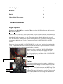
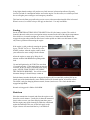
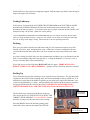
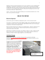
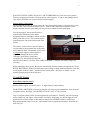
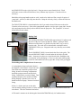
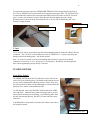
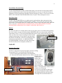
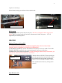
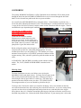
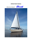
1
OPERATION MANUAL
VELOCITY
1995 Hunter 430
OWNER/HOSTS
Kirk and Lisa Knudsen
Mount Vernon. WA
2
Welcome aboard!
We are happy you have chosen Velocity for your vacation. Velocity is a Hunter 430. She was
commissioned in Seattle in 1995 and has spent much of her time in Lake Union and nearby
Puget Sound waters. Velocity was moved her to new home in Anacortes in late 2009 and now
navigates the beautiful Pacific Northwest Islands.
Velocity is currently owned by Kirk and Lisa Knudsen, and our four children, Cody (14),
Gabe (7), Samara (7), and Silas (5). It is our hope that your time aboard Velocity is both safe
and enjoyable. We are sure you will enjoy cruising the lovely islands of the Pacific Northwest
aboard Velocity.
The information provided in the manual will help you familiarize yourself with the vessel and
its systems. If you have questions concerning system operations, there is a binder located
under the Navigation station that contains individual manuals for each system on the vessel.
For any additional information feel free to shoot me an email with any question(s) you have.
We trust this manual will help you become familiar with the boat. Please remember this is a
non-smoking vessel. Always smoke outside. If you have questions about the boat or about
places to visit, please do not hesitate to ask the AYC staff.
Kirk and Lisa Knudsen
Email: [email protected]
3
VELOCITY
1995 Hunter 430
L.O.A
42’ 6”
Displacement
23,800 Lbs.
L.W.L
38’
Ballast
7,600 Lbs.
BEAM
14’
Sail Area
839 square ft
DRAFT
4’11”
Water Capacity
165 Gal
CRUISING RPM
3000
Engine
50 HP Yanmar
MAST HEIGHT
62’ 5”
Fuel
30 gallon diesel
Holding Tank
2/25 gal tanks
4
TABLE OF CONTENTS
Page
Boat Operation
Engine Inspection
Start-Up
Shutdown
Getting Underway
Docking
Fueling
5
6
6
7
7
Boat Electrical
A.C. (Shore) Systems
Inverter
D.C. (House) Systems
Batteries
8
8
9
Sanitation Systems
Marine Toilet
Holding Tank
Y-Valve
10
10
11
12
Water Systems
Fresh Water Tanks
Fresh Water Pump
Hot Water
Shower
12
12
13
13
13
Galley
Stove/Oven
Refrigeration
13
13
14
Heating Systems
Diesel Heater (DC)
14
14
Electronics
VHF Radio, Depth Sounder, Radar
GPS/Plotter
15
15
Entertainment
AM/FM Radio
CD Player
TV/DVD
15
15
15
15
Anchoring/Mooring
16
7
5
Sails/Furling Systems
17
Barbecue
17
Dinghy
18
Other: Safety/Bilge Pumps
18
Boat Operation
Engine Inspection
Remember your “WOBBS” every morning: Water (Coolant), Oil, Bilges (Inspect and Pump-out),
Belts and Sea Strainer.
Check the level of COOLANT in the expansion tank. Engine coolant is a mixture of 50% antifreeze
and water. Check the level of OIL in the engine with the dipstick located on the Port side accessible
through cabin ladder access panel. A pair of etch marks on each dipstick indicates the proper oil
level. Do not overfill! Make sure the dipstick is firmly put back in! Check the oil with a paper towel
or a rag, never the dish towel! Check the general condition of the BELTS, HOSES, and FUEL
LINES.
Ensure the valve on each RAW WATER THRU-HULL is in the ‘open’ position (lever in-line with
valve). Your thru-hull and strainer are located on the aft end of the engine compartment accessible
from the aft cabin engine compartment panel (under cabin stairs).
Observe the glass of each RAW WATER STRAINER for
debris. If necessary, close the seacock, open the strainer
cover, clean the strainer, and reassemble. Be careful to seat
the O ring properly or you will have a leak. REOPEN THE
THRU-HULL!
Fuel water Separator
Raw water strainer
Engines
Fuel filter
Velocity has a 50 horsepower diesel engine, which drives a
two-bladed propeller through a reversible transmission. The
combined shift lever and throttle control is along with the
alarms for oil and temperature, and RPM gauge. The
Oil filleraudible
cap
engine stop is located just inside the cabin hatch against the
bulkhead. The engine will propel the vessel to 7 knots in calm
water at 3000 RPM. Your best cruising is at 2400 RPM for
longer periods.
6
Using higher throttle settings will produce very little increase in forward speed but will greatly
increase fuel and oil consumption and the wear on the engine. For this reason, we ask that you limit
the use of higher power settings to real emergency situations.
This boat has a definite prop walk to the port in reverse with not much noticeable affect in forward.
When in reverse, be careful to keep a firm grip on the wheel. Use only low RPMs. .
Starting
Set the STARTER BATTERY SELECTOR SWITCH to ON (See battery section). The switch is
located in the main cabin, next to navigation station, mounted on the side of the engine compartment.
Place shift lever in neutral (straight up in center). Note there is a button under the throttle that
engages the engine when pushed in and releases it when pulled out. Make sure this button is in the
out (release) position when starting the engine.
If the engine is cold, preheat by rotating the ignition
key to “GLOW” for 10 sec. Turn the key to the
START position. After the engine catches, check
your transom for water exiting with the exhaust.
Allow the engine to warm up by idling for 10
minutes at about 1000 RPM before putting under
load.
Do not hold ignition key in START for more than
15 seconds at a time. If the engine does not start the
first time, WAIT for about 15 seconds before trying
again. NEVER TURN THE KEY OFF WHILE
THE ENGINE IS RUNNING! You will do serious
alternator damage. It should always remain on.
Push the button in under the throttle to engage the engine (still in neutral idle position) Pull up on
clutch (part of the throttle handle), move throttle forward for forward motion, or back for reverse.
The clutch is only for changing between neutral, forward, and reverse. The clutch should not be
engaged at high RPM.
Normal cruising speed is 2000 to 3000 RPM.
Shutdown
Place the transmission in neutral and allow the engine to cool
down for several minutes. Usually this is about the amount of
time it takes to secure your lines and plug into shore power.
Pull the engine stop switch located just inside the cabin hatch
against the bulkhead. This cuts off the fuel supply to the
engine. Alarms will sound until the key is switched off.
Engine shutdown switch
7
Switch off the key after engine has completely stopped. Push the engine stop back in after the engine
stops or the engine will not restart.
Getting Underway
To disconnect, first turn off the AC POWER CIRCUIT BREAKER on the ELECTRICAL PANEL.
Disconnect the POWER CORD from the boat inlet located on the stern (starboard side). Last,
disconnect the shore receptacle. To reconnect shore power, plug in cord, turn on shore breaker, and
then turn on ship’s AC breaker. Watch for reverse polarity.
Close the PORTHOLES, WINDOWS, and FORWARD HATCH. Once outside the marina, idle the engines
while crew brings in fenders and lines. Assign one crew member to be in charge of securing ports and assign
one to be in charge of the dinghy if towing. Shorten the line on all close-quartering maneuvers.
Docking
Have your crew make-ready the lines and fenders and give clear instructions on how you will be
docking. Have bow, stern, and spring lines ready. Often times it is best to lead them to the mid
section of the boat (the fattest part) where your crew member can easily step off and secure either
one.
As you are coming in to dock, have your best communicator mid ships to give you distances from the
dock. It is often hard to judge how close the dock is. Calling out distances (i.e. 20 feet, 10 feet, 4
feet etc.) will only add to a successful docking.
If you find you are too far off the dock, BACK OFF and do it again. THERE WILL BE NO
HEROIC JUMPING OF CREW MEMBERS! Disaster will hit if you loose someone overboard.
Fueling Up
You will need to fuel up before returning to your slip at the end of your charter. The fuel tank holds
50 gallons of diesel fuel. Before pumping, have an oil/fuel sorbs handy to soak up spilled fuel. You
should have a rough idea of the number of gallons you will need by the engine hour indicator. Your
vessel uses, approximately, 1.2 gal/hr. Also periodically have someone go down below to watch the
fuel gauge located below the circuit breaker panel. ENSURE THE “TANK INDICATOR”
CIRCUIT BREAKER IS ON AND THE TANK SELECTOR SWITCH IS SET TO “F”!
The fuel deck cap is located aft of the Helm, on the port
side, next to the life rail. CHECK THAT YOU HAVE THE
CORRECT DECK OPENING! Use only DIESEL! Do not
add water or pump-out at the same time you are fueling.
Tank indicator
circuit breaker
Place the DIESEL nozzle into the tank opening, pump
slowly and evenly, and note the sound of the fuel flow.
Fuel Gauge (ensure
selector is on “F”)
8
Pumping too fast may not allow enough time for air to escape, which may result in spouting from the
tank opening. As the tank fills, the sound will rise in pitch or gurgle. Pay attention to the TANK
OVERFLOW VENT on the outside of the hull on the port side. The sound may indicate that the tank
is nearly full. Top off carefully, and be prepared to catch spilled fuel. Spillage may result in a nasty
fine from law enforcement. Replace deck cap
Caution -- Clean up splatter and spillage immediately for environmental and health reasons. Wash
hands with soap and water thoroughly.
BOAT SYSTEMS
Electrical Systems
The electrical system is divided into two distribution systems: 110-volt AC and 12-volt DC.
The systems are controlled from the AC ELECTRICAL PANEL, the DC AUXILIARY PANEL, both
located above navigation station, and the BATTERY SWITCHES FOUND on the side of the engine
compartment, across from the navigation station.
When not connected to shore power, batteries are providing all power. Therefore, monitor the use of
onboard electricity carefully with your voltmeter located on the Electrical Panels, and turn off
electrical devices that are not needed.
Most breakers are labeled by colored dots. Green signifies “usually on”. Red is “usually off” Blue
dots are water pressure or water-related like pumps. Yellow signifies electronics or items to use
cautiously. No dots are breakers signify irregular use or use with discretion.
110-Volt AC System
SHORE POWER supports the water heater, refrigerator/freezer, microwave, televisions,
dehumidifier, HEATER COOLANT CIRCULATION PUMP, and receptacles on board, as well as
the battery charger.
To connect to shore power: plug the POWER
CORD into the boat and then into the dock
receptacle. Check the power rating/plug size
of the nearest dock receptacle (that is 30 amp,
20 amp, or 15 amp). If necessary, add a
CORD ADAPTER located STBD of the
boarding stairs, in the stern storage
compartment. Turn the dock power on. Cords
coming off the bow can be wrapped loosely
around the bow line. IF POWER DOES
NOT TURN ON, CHECK THE CIRCUIT
BREAKER UNDER THE AFT STBD
COCKPIT SEAT!
A/C circuit breaker &
Storage compartment for Electrical
cords and adapters.
9
At the ELECTRICAL PANEL, flip the AC CURCUIT BREAKER on. Check for reverse polarity.
Then turn on appropriate breakers for water heater, and refrigerator. If you are not getting power to
your outlets, check that one of your GFIs has not been tripped.
Inverter Power (110-volt AC)
The INVERTER provides AC power only to the 110-volt receptacle plugs (i.e. the microwave oven)
when the boat is disconnected from shore power. Shut off water heater and refrigerator circuit
breaker when the inverter is providing power to prevent your batteries from going dead.
Your inverter panel, with an on/off switch, is
located on the STBD side of the engine
compartment next to the battery selector switches.
Make certain that it is on. The actual inverter is
located under the seat on the forward end of the
aft bed.
Inverter Panel
The inverter’s power source is the DC house or
inverter batteries located at the base of the cabin
stairs, under the floor. The quantity of DC power
is limited to the capacity of these batteries...
Therefore, running hair dryers, toaster,
coffeepots, space heater, water heater,
refrigerator, etc will quickly discharge the
house/inverter batteries. Use these items VERY SPARINGLY! Monitor your battery usage very
carefully!
When connected to shore power, the inverter automatically becomes a battery charger for the 12-volt
HOUSE BATTERIES. Should you detect the inverter failing to charge the house batteries, check the
circuit breaker in the AC Panel. And the inverter control panel. Also, there is usually a circuit
breakers located on top of the inverter box.
12-volt DC System
House Battery Bank & Switch
2 battery banks support 12-volt DC power: 1) engine battery 2) house battery
The BATTERY SWITCHES are located on the port side of the engine compartment, across from the
navigation station. Normally, leave the SWITCH in the “ALL” or “ON” position.
Your 12 volt panel shows all the systems supported by your batteries. Primarily you will be turning
on the breakers for your lights, water pressure, electronics, sump pump, etc. Interior lights are also
powered from a circuit breaker on this panel but many have individual switches at each fixture.
Bilge pumps should always be left on. Your breakers such as propane should always be turned off
after every use.
10
The HOUSE BATTERY BANK provides power for all DC systems. When disconnected from shore
power, all 12-volt devices and 110-volt devices drain the house battery.
Battery systems will lose their charge while ANCHORED or MOORED. Avoid this by using power
sparingly at anchor. Turn the refrigerator off at night. Use only one or two lights at a time. Turn off
systems not in use such as instruments, VHF, stereo, etc. If you do not need the cabin heater, turn it
off. If you stay moored for more then a day, run your engines just above idle to recharge your
batteries. WATCH YOUR VOLTAGE!
Batteries are charged by the engine ALTERNATORS while underway. The engine/house batteries
are charged by the BATTERY CHARGER when connected to shore power.
There are two 12 volt auxiliary plugs – one located on the electrical panel and the other on the helm
in the cockpit. Both of these operate off battery power alone. The electrical outlets will not work
under the DC battery system.
Note -- Do not change the position of the switches while the engines are running or the alternator
diodes will be damaged. Change positions with the engines off.
Voltage (Wet Cell Battery)
12.65 volts
12.47 volts
12.25 volts
11.95 volts
11.70 volts
Battery State
100%
75%
50%
25%
0%
SANITATION SYSTEM
Marine Toilet
It is important that every member of the crew be informed on the proper use of the MARINE
TOILET. The valves, openings, and pumps are small and may clog easily. If the toilet clogs, it is
YOUR RESONSIBILITY! Always pump the head for a child so you can make sure nothing foreign
is being flushed.
Caution – Never put paper towels, tampons, Kleenex,
sanitary napkins, household toilet paper, or food into
the marine toilet. Use only the special dissolving
marine toilet tissue provided by AYC.
To use the toilet, move the PUMP LEVER to the
‘left’ (wet bowl). Lift the PUMP HANDLE 3 to 5
times to wet the bowl. After using the toilet, lift the
PUMP HANDLE to wet the bowl again. Then, move
Hand Pump
Pump Lever
11
the PUMP LEVER to the ‘right’ (dry bowl). Pump to remove water from the bowl. Flush
sufficiently to move effluent in the hoses; heavy effluent may clog hoses. Clean the toilet as
necessary.
Should the toilet pump handle squeak or stick, it needs to be lubricated. Put a couple of squirts of
‘pump lube’, salad oil, or dish soap into the toilet. Pump the toilet dry slowly, to draw the lube into
the handle unit.
The TOILET TRU-HULL is located under the sink if you need to shut off the water to the toilet.
Clean the toilet as necessary. If the toilets pump handle squeaks or sticks squirt ‘pump lube’ into the
toilet and pump the toilet slowly to draw the lube into the pump unit. The ‘pump lube’ is located
behind the mirrored cabinet.
Holding Tank
Toilet ThruHull
The sanitation HOLDING TANKS holds approximately 25 gallons each.
Be aware of the rate of waste production. (about 1 gallon per flush)
With an overfilled tank, it is possible to break a hose, clog a vent, or
burst the tank. The result will be indescribable catastrophe and an
EXPENSIVE FIX to you. Empty the tank every other day to avoid this
problem.
The aft HOLDING TANK is located under the floor in the galley. The
forward HOLDING TANK is located under the bed in the forward
cabin. Some may be subject to a visual check with a flashlight or the
“watermelon” test by thumping it. There is a tank watch warning light
located in each head but do not rely upon this as they often get clogged.
The holding tank is emptied in one of two ways:
#1 At the Marine Pump out Station, Remove
the WASTE CAPS located: Aft port side and
Fwd STBD side. Install the pump out deck
fitting, located in aft storage compartment.
Attach the pump-out nozzle onto the deck
fitting. Double-check your deck fitting! Turn
on pump and open valve located on handle.
When pumping is finished, close lever on
handle and turn off pump. Remove from deck
fitting.
“Tank watch” warning
light
If there is a fresh water hose on the dock,
rinse the tank by adding 2 minutes of water into tank. Then repump to leave the tank rinsed for the
next charter. This also eliminates head odors.
#2 The tank’s contents can be discharged with the MACERATOR only in Canadian waters.
12
To operate the macerator, open the OVERBOARD THRU-HULL for the appropriate tank (fwd or
aft). The aft THRU-HULL is located under an access panel in the galley floor. The fwd Thru-HULL
is located under the fwd bed. Then turn on the MACERATOR circuit breaker on the DC electrical
panel. Listen to the macerator’s sound. When the pitch becomes higher, the tank is empty.
Discharge may be observed on the fwd starboard side, or aft port side. It should only take a few
minutes to empty the tank.
AFT THRU-HULL
Forward THRU-HULL
Y-Valve
The Y-VALVE directs waste effluent into the sanitation-holding tank or flushes the effluent ‘directly
overboard’. The Y-VALVE is located adjacent to the aft THRU-HULL. A plastic strap keeps the
handle pointed to the holding tank – the normal position.
Note -- Y-valves are usually wire-tied to the holding tank position in respect to Coast Guard
regulations. Please leave it “as is” unless there is an emergency. Be familiar with the applicable
laws concerning dumping sewage directly overboard.
WATER SYSTEMS
Fresh Water Tank(s)
The FRESH WATER tanks hold 165 gallons in 2 tanks. Observe the
water level by the indicator gauge. Be mindful of the amount of water
you use while washing dishes and taking showers. Waste water from
the sinks and showers drains overboard through various thru-hulls and
pump out boxes usually located under the sinks.
To refill the tank, remove the WATER CAPS located on the STBD
side of the deck. Attach the hose to the dock spigot and let run for a
minute before inserting into deck fitting. Avoid flushing debris from
the deck into the tank opening. DO NOT fill water and diesel at the
same time!
A MANIFOLD to switch tanks is located in the cabinet on the side of
the navigation station.
Water Tank Selector Valve
13
Fresh Water Pressure Pump
The WATER PRESSURE PUMP is located under galley seat at aft end. Activate pump at the DC
panel by turning on the breaker. If the water pump continues to run, you are either out of water or
might have an air lock and need to bleed the system by opening up a faucet. If you run out of water
SHUT OFF YOUR HOT WATER HEATER on the AC panel. Serious damage can occur!
Hot Water Tank
The HOT WATER HEATER has a ten gallon capacity tank and heats when connected to shore
power or off the heat exchanger when the engine is running. To use in the AC mode, flip on the
water heater circuit breaker on the AC electrical panel. Do not use the water heater if the water tank
level is very low. CONTINOUS HOT WATER IS ALSO AVAILABLE WITHOUT SHORE
POWER WHILE OPERATING THE VESSEL’S HEATER. (SEE PAGE 16)
Shower
Hot water for showers is available while at the pier using shore power or at anchor while operating
the vessel’s heater (see page 16).Before taking a SHOWER, make sure water pressure and shower
sump breakers are on. To activate the hand-held wand, turn on water at back of shower head. Take
only very short “boat” showers (turning off water between
soaping up and rinsing). To keep shower tidy wipe down
Fresh water shower
the shower stall and floor. Check for accumulation of hair
in the shower and sink drains. An additional FRESH
WATER SHOWER is located at swim step. Ensure that
the faucets and nozzle are completely off after use.
GALLEY
Propane Stove/Oven
The boat is equipped a low-pressure propane system for cooking.
Your propane stove is activated by the following steps:
#1 Turn on the propane tank located in aft compartment.
#2 Turn on the DC breaker labeled “LP Gas“ and the solenoid switch
located to the left
of the circuit
breaker panel.
#3 For stove: turn
on the gas at the
stove (Press in
knob) and light
burner using black
button. You might need to hold the knob in
a couple sec to warms up.
Solenoid switch
“LP Gas” circuit breaker
For oven: turn oven knob to light. Open
oven door and light pilot using a match
while holding down the red safety button.
You might need to hold the button in a
14
couple sec to warms up.
When finished cooking turn off the switches and the bottle.
Oven knob and safety button
Oven Pilot
Refrigeration
The REFRIGERATOR operates on 120-volt power. Do not use refrigeration while using inverter
power. There is a breaker on the AC panel and a thermostat inside the refrigerator. AYC will
supplement you with 2 bags of ice.
HEATING
Hydronic Furnace (AC and DC)
AC POWER FROM INVERTER OR SHORE IS REQUIRED FOR CIRCULATION PUMP.
FURNACE WILL OVERHEAT IF PUMP IS NOT OPERATING!
The HYDRONIC FURNACE provides heat and hot water while pier side or at anchor. Turn on the
TOGGLE SWITCH located below the circuit breaker panel. Set any one of the three
THERMOSTATs to the desired temperature. If you are utilizing the furnace solely for hot water; you
must turn one of the three thermostats up to start furnace.
HEATER TOGGLE
SWITCH
Check the furnace EXHAUST located at the port
stern for any obstruction such as fenders or lines.
Do not block this opening when operating the
furnace. Heat will damage fiberglass or rubber.
Turn ‘off’ the furnace heater by turning switch
back off.
Space Heaters (AC)
15
Two 120-volt SPACE HEATERS are available when connected to shore power. Both can be found
in under the seat in the aft stateroom. FOR BACKUP USE ONLY!
ELECTRONICS
All electronic manuals are located under the navigation desk.
VHF Radio
The VHF radio is located at the helm. Make sure the VHF Radio breaker is on located at the DC
panel. Turn it on before departing the pier. Monitor channel 16 at all times.
Depth Sounder
There is 1 DEPTH SOUNDER located on the arch in the cockpit. To activate the DEPTH
SOUNDER, turn on the instrument breaker on the DC panel. The sounder should provide reliable
readings in shallow waters. If in doubt, switch it off, then turn it back on to reset sounder. If your
reading is blinking, it is a FALSE reading. False readings can occur in depths of more then 200 feet
or in areas of string currents or tides.
Global Positioning System (GPS)
A fixed mount GPS is on the arch in the cockpit. Ascertain that your breaker is on at the DC breaker panel..
Refer to the manual normally found in the navigation desk. GPS is considered a navigation aid. Do not rely on
it. Compasses, charts, and dividers are the tools to plot position, course, and speed.
Wind Speed and Surface Speed indicators
Along with the GPS and depth sounder; mounted on the cockpit arch are the wind speed and direction indicator,
and the surface speed indicator. To turn these units on: locate and close the instrument circuit breaker on the
main DC electrical panel at the navigation station.
ENTERTAINMENT SYSTEMS
AM/FM Stereo Radio
The JVC brand CD/DVD unit is located beneath the circuit breaker panel. It operates like a normal
car radio. There are 8 speakers (stereo) throughout the vessel, located in each cabin and cockpit.
Each area has a volume control. The DVD player function displays on AM/FM/DVD
the televisionSTEREO
mounted in the
main cabin.
TV/VCR
A TV in the main cabin is used in conjunction with the above AM/FM stereo to watch DVDs. A
TV/DVD is also stored in the aft cabin.
16
ANCHORING
The primary WORKING ANCHOR is a 45lb. CQR anchor and is attached to 250 ft. chain passed
through the deck from the ANCHOR LOCKER the locker can be accessed through the bow deck
hatch. Use the forward foot pedals at the bow to operate windlass.
Let out sufficient ANCHOR RODE before setting the anchor. Colored markers are placed every --feet on the chain, indicating the amount of rode. If the anchorage is crowded put down at least a 3 to
1 scope (60 feet for 20 feet of water), back the anchor in with a short burst from the engine. Then let
out additional scope dependent upon conditions.
THE WINDLASS BREAKER IS
LOCATED ON THE BATTERY
SLECTOR PANEL.
Coordinate the maneuver with the
helmsperson to remain steady above the
anchor as it is raised. As the anchor rises,
be careful not to allow it to swing against the
hull. Wash it down if you have a wash down
pump before it goes into anchor locker.
Windlass breaker
Before raising the anchor, start the engines. As the boat moves toward the anchor, press the ‘up’
control to take up slack line, rather than pulling tight line. Give the
windlass short rests as you are pulling it up. The windlass uses a large
amount of electrical power; so ALWAYS operate the windlass with the
Windlass controls
engines running. Place yourself in position to guide the anchor onto the
roller,
A SPARE 45lb. CQR ANCHOR is normally stowed with the working
anchor. The, 250 ft., SPARE ANCHOR RODE is attached to the
anchor.
Mooring Cans
The State Park Sticker on your vessel allows you to pick up the
MOORING CANS in the parks for free. You only need to register at the
kiosk usually located at the heads of the docks. Mooring cans have a
metal triangle at the top upon which is a metal ring. The metal ring is
attached to the chain which secures your boat. IT IS VERY HEAVY.
The strongest member of your crew should be picked for this job.
Come up to the CAN into the wind as you would for anchoring. Have crew members on the bow,
one with a boat hook and one with a mooring line secured like a bow line. As you are coming slowly
up to the can have the crew holding the boat hook point at the can with the hook so the skipper
always knows where it is. Hook the can and bring the ring up to the boat to allow the second crew to
thread the ring with the line. Release the hold with the boat hook. If your mooring line is led out the
17
starboard chock bring the end of the line back through the port side. You will essentially create a
bridle with about 10 feet of slack from the chalk to the can.
SAILS AND RIGGING
The 110% JIB is furled. The furling line is starboard of the cockpit. To unfurl the headsail, (a)
uncleat the furling lines, (b) wrap the sheet around the appropriate winch, (c) pull the sheet aft while
maintaining tension on the furling line, (d) cleat when desired reefing level has been achieved. To
furl the jib, apply slight tension on the jib sheet while pulling on the furling line until there are three
wraps to hold the sail.
Jib sheets are led back to the cockpit to the main winches. Use the jib sheet ‘stoppers’ as little as
possible as they tend to fray the lines badly. Adjust fairleads forward in heavy wind, aft in light wind.
The MAINSAIL has jiffy reefing that is led to the cockpit in four reefing lines. To apply a reef go
head to wind, lower the main halyard, pull in on the desired reef line sufficiently, and then raise the
halyard and resume sailing.
Jib sheets, reef lines, mainsheet, halyards, and traveler are all operated from the cockpit. There is a
soft boomvang. A lazyjack system simplifies sail handling. There is no solid boomvang, no whisker
pole, and no spinnaker setup. There is a topping lift which needs to be released after hoisting the
mainsail and reset at the mast on dropping the main.
Troubleshooting:
1. Mainsail resists being raised. Check all lines. Both reefing lines should be pulled loose and
flopping. The boomvang should be loose. The battens should not be stuck on the lazyjack. If they
are, lower the sail and be sure to be head to wind on raising the sail again.
2. Furling line gets stuck partway through the furling process. This is usually due to not applying
proper tension on lines in furling and unfurling process. Try letting the sail out and repeating the
process. Be sure you are headed into the wind to reduce pressure on the rig. If this fails you could
have an over-ride in the furling drum.
3. Unable to point with reef in place. Probably have not snugged the reef line sufficiently. Repeat
process and be sure lines are snug before raising the halyard.
4. There are so many other problems – but that’s what being a sailor is all about!
BARBECUE
The BARBECUE and MOUNTING BRACKET are stored in the aft STBD storage compartment.
Place on MOUNTING BRACKET, attached to the aft port side life rail. Reverse the procedure to
dismount barbecue. Attach a PROPANE BOTTLE to the REGULATOR. Carefully light the unit,
preferably with a long-stem butane lighter. The barbecue generates a lot of heat and cooks hot and
fast. Store the barbecue unit back in the storage compartment after cooled down. Please wipe with a
paper towel before storing to prevent grease and dirt soiling the boat.
18
Note: Propane bottles are not stocked by AYC. You will need to purchase one if extras are not found
on board.
Caution -- For safety reasons, do not store an opened propane bottle within the salon or engine
compartment. Chances are these will leak slightly once opened and propane gas could settle into
low spaces. Store these bottles in the cockpit cabinet. Ensure gasoline and flammable materials are
not near the barbecue.
DINGHY
Your 9’ BOMBARD DINGHY has a capacity of about 800 pounds (motor, equipment, and 4
people). Be sure when towing your dinghy, that one responsible individual is always keeping an eye
on its tow rope when slowing down or stopping. Bring up all the slack to prevent a wrap around the
prop.
When rowing your dinghy to shore, use EXTREME CAUTION. Choose an area free of any large
rocks that might cause harm in beaching. Lift up on the dinghy to bring it up to higher ground.
NEVER drag it! Secure it when leaving as the tides come up very quickly.
OTHER/SAFETY EQUIPMENT
SAFETY should be paramount in your daily cruising. A MAN OVERBOARD DRILL should be
discussed and perhaps even practiced with a life jacket. Remember your lifejackets are stowed under
the STBD aft cockpit seat. A few should always be out and ready. Your fares and safety equipment
are located under the cup holder at the front of the helm.
Velocity is equipped with an AUTOMATIC BILGE PUMP. The master switch is located on the DC
electrical panel. Normally, the switch will be left in the AUTO position. You may occasionally hear
the pump operate due to condensation and water from the shaft log accumulating
in the bilge.
Manual bilge pump
An AUXILIARY HAND OPERATED BILGE PUMP is operated near the
boarding stairs in the cockpit using the handle provided for that purpose (under
the port cockpit seat). This is used only in emergency situations.
A SPARE PROPELLER is found in cabinet on the side of the navigation station.
(emergency only)