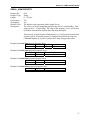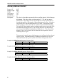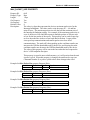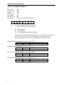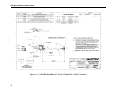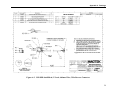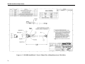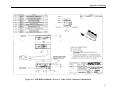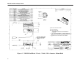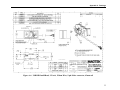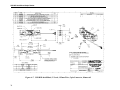
1
USB HID INTELLIHEAD
FOR SWIPE READERS
TECHNICAL REFERENCE MANUAL
Manual Part Number 99875320-5
OCTOBER 2008
REGISTERED TO ISO 9001:2000
1710 Apollo Court
Seal Beach, CA 90740
Phone: (562) 546-6400
FAX: (562) 546-6301
Technical Support: (651) 415-6800
www.magtek.com
ii
Copyright© 2008
MagTek®, Inc.
Printed in the United States of America
Information in this document is subject to change without notice. No part of this document may be
reproduced or transmitted in any form or by any means, electronic or mechanical, for any purpose,
without the express written permission of MagTek, Inc.
MagTek is a registered trademark of MagTek, Inc.
IntelliHead™ is a trademark of MagTek, Inc.
USB (Universal Serial Bus) Specification is Copyright© 1998 by Compaq Computer Corporation, Intel
Corporation, Microsoft Corporation, NEC Corporation.
REVISIONS
Rev Number
1
2
Date
28 Jan 05
10 Jun 05
3
17 Oct 05
4
5
13 Sept 07
14 Oct 08
Notes
Initial Release
Added examples to some of the commands; editorial
throughout; added 210401xx models
Updated Limited Warranty; added new models: 21044000 and
21046003 and updated other revisions
Added new model 21030042.
Added JIS type 2 decoding option; updated company address.
iii
LIMITED WARRANTY
MagTek warrants that the products sold to Reseller pursuant to this Agreement will perform in accordance with
MagTek’s published specifications. This warranty shall be provided only for a period of one year from the date
of the shipment of the product from MagTek (the “Warranty Period”). This warranty shall apply only to the
original purchaser unless the buyer is authorized by MagTek to resell the products, in which event, this warranty
shall apply only to the first repurchase.
During the Warranty Period, should this product fail to conform to MagTek’s specifications, MagTek will, at its
option, repair or replace this product at no additional charge except as set forth below. Repair parts and
replacement products will be furnished on an exchange basis and will be either reconditioned or new. All replaced
parts and products become the property of MagTek. This limited warranty does not include service to repair
damage to the product resulting from accident, disaster, unreasonable use, misuse, abuse, customer’s negligence,
Reseller’s negligence, or non-MagTek modification of the product. MagTek reserves the right to examine the
alleged defective goods to determine whether the warranty is applicable.
Without limiting the generality of the foregoing, MagTek specifically disclaims any liability or warranty for
goods resold in other than MagTek’s original packages, and for goods modified, altered, or treated by customers.
Service may be obtained by delivering the product during the warranty period to MagTek (1710 Apollo Court,
Seal Beach, CA 90740). If this product is delivered by mail or by an equivalent shipping carrier, the customer
agrees to insure the product or assume the risk of loss or damage in transit, to prepay shipping charges to the
warranty service location and to use the original shipping container or equivalent. MagTek will return the product,
prepaid, via a three (3) day shipping service. A Return Material Authorization (RMA) number must accompany
all returns.
MAGTEK MAKES NO OTHER WARRANTY, EXPRESS OR IMPLIED, AND MAGTEK DISCLAIMS ANY
WARRANTY OF ANY OTHER KIND, INCLUDING ANY WARRANTY OF MERCHANTABILITY OR
FITNESS FOR A PARTICULAR PURPOSE.
EACH PURCHASER UNDERSTANDS THAT THE MAGTEK PRODUCT IS OFFERED AS IS. IF THIS
PRODUCT DOES NOT CONFORM TO MAGTEK’S SPECIFICATIONS, THE SOLE REMEDY SHALL BE
REPAIR OR REPLACEMENT AS PROVIDED ABOVE. MAGTEK’S LIABILITY, IF ANY, TO RESELLER
OR TO RESELLER’S CUSTOMERS, SHALL IN NO EVENT EXCEED THE TOTAL AMOUNT PAID TO
MAGTEK BY RESELLER UNDER THIS AGREEMENT. IN NO EVENT WILL MAGTEK BE LIABLE TO
THE RESELLER OR THE RESELLER’S CUSTOMER FOR ANY DAMAGES, INCLUDING ANY LOST
PROFITS, LOST SAVINGS OR OTHER INCIDENTAL OR CONSEQUENTIAL DAMAGES ARISING OUT
OF THE USE OF OR INABILITY TO USE SUCH PRODUCT, EVEN IF MAGTEK HAS BEEN ADVISED OF
THE POSSIBILITY OF SUCH DAMAGES, OR FOR ANY CLAIM BY ANY OTHER PARTY.
LIMITATION ON LIABILITY
EXCEPT AS PROVIDED IN THE SECTIONS RELATING TO MAGTEK’S LIMITED WARRANTY,
MAGTEK’S LIABILITY UNDER THIS AGREEMENT IS LIMITED TO THE CONTRACT PRICE OF THE
PRODUCTS.
MAGTEK MAKES NO OTHER WARRANTIES WITH RESPECT TO THE PRODUCTS, EXPRESSED OR
IMPLIED, EXCEPT AS MAY BE STATED IN THIS AGREEMENT, AND MAGTEK DISCLAIMS ANY
IMPLIED WARRANTY, INCLUDING WITHOUT LIMITATION ANY IMPLIED WARRANTY OF
MERCHANTABILITY OR FITNESS FOR A PARTICULAR PURPOSE.
MAGTEK SHALL NOT BE LIABLE FOR CONTINGENT, INCIDENTAL, OR CONSEQUENTIAL
DAMAGES TO PERSONS OR PROPERTY. MAGTEK FURTHER LIMITS ITS LIABILITY OF ANY KIND
WITH RESPECT TO THE PRODUCTS, INCLUDING ANY NEGLIGENCE ON ITS PART, TO THE
CONTRACT PRICE FOR THE GOODS.
MAGTEK’S SOLE LIABILITY AND BUYER’S EXCLUSIVE REMEDIES ARE STATED IN THIS SECTION
AND IN THE SECTION RELATING TO MAGTEK’S LIMITED WARRANTY.
iv
FCC WARNING STATEMENT
This equipment has been tested and found to comply with the limits for Class B digital device, pursuant to Part 15
of FCC Rules. These limits are designed to provide reasonable protection against harmful interference when the
equipment is operated in a residential environment. This equipment generates, uses, and can radiate radio
frequency energy and, if not installed and used in accordance with the instruction manual, may cause harmful
interference to radio communications. However, there is no guarantee that interference will not occur in a
particular installation.
FCC COMPLIANCE STATEMENT
This device complies with Part 15 of the FCC Rules. Operation of this device is subject to the following two
conditions: (1) This device may not cause harmful interference; and (2) this device must accept any interference
received, including interference that may cause undesired operation.
CANADIAN DOC STATEMENT
This digital apparatus does not exceed the Class B limits for radio noise for digital apparatus set out in the Radio
Interference Regulations of the Canadian Department of Communications.
Le présent appareil numérique n’émet pas de bruits radioélectriques dépassant les limites applicables aux
appareils numériques de las classe B prescrites dans le Réglement sur le brouillage radioélectrique édicté par les
ministère des Communications du Canada.
CE STANDARDS
Testing for compliance to CE requirements was performed by an independent laboratory. The unit under test was
found compliant to Class B.
UL/CSA
This product is recognized per Underwriter Laboratories and Canadian Underwriter Laboratories 1950.
RoHS STATEMENT
When ordered as RoHS compliant, this product meets the Electrical and Electronic Equipment (EEE) Reduction
of Hazardous Substances (RoHS) European Directive 2002/95/EC. The marking is clearly recognizable, either as
written words like “Pb-free” or “lead-free”, or as another clear symbol (
).
v
TABLE OF CONTENTS
SECTION 1. FEATURES AND SPECIFICATIONS..................................................................................... 1 FEATURES............................................................................................................................................... 1 HARDWARE CONFIGURATIONS ........................................................................................................... 2 ACCESSORIES........................................................................................................................................ 2 REFERENCE DOCUMENTS ................................................................................................................... 2 SPECIFICATIONS.................................................................................................................................... 3 SECTION 2. INSTALLATION...................................................................................................................... 5 USB CONNECTION ................................................................................................................................. 5 WINDOWS PLUG AND PLAY SETUP..................................................................................................... 5 MOUNTING .............................................................................................................................................. 5 SECTION 3. OPERATION........................................................................................................................... 7 CARD READ............................................................................................................................................. 7 SECTION 4. USB COMMUNICATIONS...................................................................................................... 9 HID USAGES............................................................................................................................................ 9 REPORT DESCRIPTOR ........................................................................................................................ 10 CARD DATA ........................................................................................................................................... 11 TRACK 1 DECODE STATUS................................................................................................................. 11 TRACK 2 DECODE STATUS................................................................................................................. 12 TRACK 3 DECODE STATUS................................................................................................................. 12 TRACK 1 DATA LENGTH ...................................................................................................................... 12 TRACK 2 DATA LENGTH ...................................................................................................................... 12 TRACK 3 DATA LENGTH ...................................................................................................................... 12 CARD ENCODE TYPE........................................................................................................................... 13 TRACK DATA ......................................................................................................................................... 13 TRACK 1 DATA ...................................................................................................................................... 13 TRACK 2 DATA ...................................................................................................................................... 13 TRACK 3 DATA ...................................................................................................................................... 13 COMMANDS .......................................................................................................................................... 14 COMMAND NUMBER ............................................................................................................................ 14 DATA LENGTH....................................................................................................................................... 14 DATA ...................................................................................................................................................... 14 RESULT CODE ...................................................................................................................................... 15 GET AND SET PROPERTY COMMANDS ............................................................................................ 15 SOFTWARE_ID PROPERTY ................................................................................................................. 16 SERIAL_NUM PROPERTY .................................................................................................................... 17 POLLING_INTERVAL PROPERTY........................................................................................................ 18 MAX_PACKET_SIZE PROPERTY......................................................................................................... 19 TRACK_ID_ENABLE PROPERTY......................................................................................................... 20 INTERFACE_TYPE PROPERTY ........................................................................................................... 21 DECODE_ENABLE PROPERTY ........................................................................................................... 22 RESET_DEVICE COMMAND ................................................................................................................ 23 SECTION 5. DEMO PROGRAM ............................................................................................................... 25 INSTALLATION ...................................................................................................................................... 25 OPERATION........................................................................................................................................... 25 SOURCE CODE ..................................................................................................................................... 26 APPENDIX A. DRAWINGS ....................................................................................................................... 27 vi
TABLES AND FIGURES
Figure 1-1. USB IntelliHead 3-Track .......................................................................................................... viii Table 1-1. Specifications.............................................................................................................................. 3 Table 2-1. 5-Pin Connector .......................................................................................................................... 5 Figure A-1. USB HID IntelliHead, 3-Track, 125mm Wire, 5-Pin Connector............................................... 28 Figure A-2. USB HID IntelliHead, 3-Track, 440mm Wire, 5-Pin Reverse Connector ................................ 29 Figure A-3. USB HID IntelliHead, 3-Track, 125mm Wire, 4.05mm Beam Arm, 5-Pin Molex .................... 30 Figure A-4. USB HID IntelliHead, 3-Track, 6’ Cable, USB-A Connector, 100mm Black ........................... 31 Figure A-5. USB HID IntelliHead, 3-Track, 6” Cable, USB-A Connector, 100mm Black ........................... 32 Figure A-6. USB HID IntelliHead, 3-Track, 125mm Wire, 5-pin Molex connector, 43mm rail ................... 33 Figure A-7. USB HID IntelliHead, 3-Track, 125mm Wire, 5-pin Connector, 90mm rail ............................. 34 Figure A-8. USB HID IntelliHead, 3-Track, 125mm Wire, 5-pin Molex Connector, 60mm Slim Profile ..... 35 Figure A-9. USB HID IntelliHead, 3-Track, 125mm Wire, 5-pin Molex Connector, 90mm Slim Profile ..... 36 vii
Figure 1-1. USB IntelliHead 3-Track
viii
SECTION 1. FEATURES AND SPECIFICATIONS
The USB (Universal Serial Bus) HID (Human Interface Device) IntelliHead Swipe Reader is a
compact magnetic stripe card reader that conforms to ISO standards. The Reader is compatible
with any device with a USB host interface. A card is read by sliding it past the head either
forward or backward.
The Reader conforms to the USB HID Class specification Version 1.1. This allows host
applications designed for most versions of Windows to easily communicate to the device using
standard Windows API calls that communicate to the device through the HID driver that comes
with Windows.
Unlike HID keyboard emulation readers, this device does not use keyboard emulation. It
behaves like a vendor-defined HID device so that a direct communication path can be established
between the Host application and the device without interference such as keystrokes from other
HID devices. (For information on the USB KB Emulation IntelliHead, refer to Technical
Manual 99875321.)
FEATURES
Major features of the USB IntelliHead are as follows:
•
•
•
•
•
•
•
•
•
•
•
•
Powered through the USB – no external power supply required
Hardware Compatible with PC or any computer or terminal with a USB interface
Bi-directional card reading
Reads encoded data that meets ANSI/ISO/AAMVA/JIS Type 2 standards and others such
as ISO track 1 format on track 2 or 3
Reads up to three tracks of card data
Compatible with USB specification Revision 1.1
Compatible with HID specification Version 1.1
Can use standard Windows HID driver for communications. No third part device driver
is required.
Programmable USB serial number descriptor
Programmable USB Interrupt In Endpoint polling interval
Non-volatile memory for configuration storage
Ability to convert to Keyboard Emulation mode of operation
1
USB HID IntelliHead Swipe Reader
HARDWARE CONFIGURATIONS
The hardware configurations are as shown in the table below. Drawings of each model are
included in Appendix A.
Part
Description
Number
21030006 USB HID IntelliHead on spring
21030010 USB HID IntelliHead on spring
21030032 USB HID IntelliHead on spring
21030042
21040124
21040128
21044000
21045087
21046003
21047011
USB HID IntelliHead on beam
USB HID IntelliHead Black
USB HID IntelliHead Black
USB HID IntelliHead 43mm rail
USB HID IntelliHead on rail
USB HID IntelliHead 60mm Slim rail
USB HID IntelliHead Slim rail
Cable Length and
Connector Type
125mm, 5 pin Molex
440mm, 5 pin Molex
(reverse pin out)
280mm, 5 pin Molex
(reverse pin out)
125mm, 5 pin Molex
1.8m (6’), USB-A
150mm (6”), USB-A
125mm, 5 pin Molex
125mm, 5 pin Molex
125mm, 5 pin Molex
125mm, 5 pin Molex
Rail or Housing
None
None
None
4.05mm Beam Arm
100mm Black enclosure
100mm Black enclosure
43mm Black rail
90mm Black rail
60mm Black slim rail
90mm Black slim rail
ACCESSORIES
The accessories are as follows:
Part Number
21042806
21051534
99510026
Description
USB MSR Demo Program with Source Code (Disk)
Test Cable to convert from IntelliHead to USB-A (6 ft)
USB MSR Demo Program with Source Code (WEB)
REFERENCE DOCUMENTS
MagTek Magnetic Card Reader Design Kit Technical Specification (99821002)
MagTek USB KB IntelliHead for Swipe Readers, Technical Reference Manual (99875321)
Axelson, Jan. USB Complete, Everything You Need to Develop Custom USB Peripherals, 1999.
Lakeview Research, 2209 Winnebago St., Madison WI 53704, 396pp., http://www.lvr.com
USB Human Interface Device (HID) Class Specification Version 1.1
USB (Universal Serial Bus) Specification, Version 1.1, Copyright© 1998 by Compaq Computer
Corporation, Intel Corporation, Microsoft Corporation, NEC Corporation
USB Implementers Forum, Inc., www.usb.org
2
Section 1. Features and Specifications
SPECIFICATIONS
Table 1-1 lists the specifications for the USB IntelliHead.
Table 1-1. Specifications
Reference Standards
Power Input
Recording Method
Message Format
Card Speed
ISO 7810, ISO 7811, AAMVA and JIS X 6302*
5V from USB bus
Two-frequency coherent phase (F2F)
ASCII
3 to 60 ips (7.62 – 152.4 cm/s)
ELECTRICAL
Current
Normal Mode
Suspend Mode
Weight
Cable length
Connector
15mA
200 µA
MECHANICAL
1.1 oz. (31 gr.)
See related drawing in Appendix A
See related drawing in Appendix A
ENVIRONMENTAL
Temperature
Operating
-40 oC to +70 oC (-40 oF to 158 oF)
Storage
-40 oC to +70 oC (-40 oF to 158 oF)
Humidity
Operating
10% to 90% noncondensing
Storage
10% to 90% noncondensing
Altitude
Operating
0-10,000 ft. (0-3048 m.)
Storage
0-50,000 ft. (0-15240 m.)
* ISO (International Standards Organization, AAMVA (American Association of Motor
Vehicle Administrators) and JIS (Japanese Industrial Standard).
3
USB HID IntelliHead Swipe Reader
4
SECTION 2. INSTALLATION
This section describes the cable connection, the Windows Plug and Play Setup, and the physical
mounting of the unit.
USB CONNECTION
Since the USB IntelliHead is supplied as an OEM product, the installation and system integration
will be unique for each application. The reader module must be attached to an appropriate
connector which, in turn, connects to the USB port or hub. The pin numbers for the 5-pin
connector are shown in Figure 2-1.
Pin numbers and signal descriptions for the cable shown in the illustration are listed in Table 2-1.
The connector is a Molex 52021-0500; one of the recommended mating connectors is Molex
53048-0510.
Table 2-1. 5-Pin Connector
Pin Number
1
2
3
4
5
Signal
VBUS
- Data
+Data
Ground
Head Case
Cable Color
Red
White
Green
Black
Brown
WINDOWS PLUG AND PLAY SETUP
On hosts with the Windows operating system, the first time the device is plugged into a specific
USB port, Windows will pop up a dialog box, which will guide you through the process of
installing a device driver for the device. After this process is completed once, Windows will no
longer request this process as long as the device is plugged into the same USB port. The device
driver that Windows will install for this device is the driver used for HID devices and it is part of
the Windows operating system. When the dialog box pops up, follow the instructions given in
the dialog box. Sometimes Windows will find all the files it needs on its own without giving any
prompts. Other times Windows will need to know the location of the files it needs. If Windows
prompts for the file locations, insert the CD that was used to install Windows on your PC and
point Windows to the root directory of the CD. Windows should find all the files it needs there.
MOUNTING
Refer to the appropriate Appendix in this document and/or to the Magnetic Card Reader Design
Kit for complete mounting details.
5
USB HID IntelliHead Swipe Reader
6
SECTION 3. OPERATION
CARD READ
A card may be swiped past the read head at any time. The magnetic stripe must face toward the
head and may be swiped in either direction. If there is data encoded on the card, the device will
attempt to decode the data and then send the results to the host via a USB HID input report.
After the results are sent to the host, the device will be ready to read the next card.
7
USB HID IntelliHead Swipe Reader
8
SECTION 4. USB COMMUNICATIONS
This device conforms to the USB specification revision 1.1. This device also conforms with the
Human Interface Device (HID) class specification version 1.1. The device communicates to the
host as a vendor-defined HID device. The details about how the card data and commands are
structured into HID reports follow later in this section. The latest versions of the Windows
operating systems come with a standard Windows USB HID driver. Windows applications that
communicate to this device can be easily developed. These applications can communicate to the
device using standard windows API calls that communicate to the device using the standard
Windows USB HID driver. These applications can be easily developed using compilers such as
Microsoft’s Visual Basic or Visual C++. A demonstration program and its source code, written
in Visual Basic, that communicates with this device is available. This demo program can be
used to test the device and it can be used as a guide for developing other applications. More
details about the demo program follow later in this document.
It is recommended that application software developers become familiar with the HID
specification the USB specification before attempting to communicate with this device. This
document assumes that the reader is familiar with these specifications. These specifications can
be downloaded free from www.usb.org.
This is a full speed USB device. This device has a number of programmable configuration
properties. These properties are stored in non-volatile memory. These properties can be
configured at the factory or by the end user. The device has an adjustable endpoint descriptor
polling interval value that can be set to any value in the range of 1ms to 255ms. This property
can be used to speed up or slow down the card data transfer rate. The device also has an
adjustable serial number descriptor. More details about these properties can be found later in this
document in the command section.
The device will go into suspend mode when directed to do so by the host. The device will wake
up from suspend mode when directed to do so by the host. The device does not support remote
wakeup.
This device is powered from the USB bus. The vendor ID is 0x0801 and the product ID is
0x0002.
HID USAGES
HID devices send data in reports. Elements of data in a report are identified by unique identifiers
called usages. The structure of the device’s reports and the device’s capabilities are reported to
the host in a report descriptor. The host usually gets the report descriptor only once, right after
the device is plugged in. The report descriptor usages identify the devices capabilities and report
structures. For example, a device could be identified as a keyboard by analyzing the device’s
report descriptor. Usages are four byte integers. The most significant two bytes are called the
usage page and the least significant two bytes are called usage IDs. Usages that are related can
share a common usage page. Usages can be standardized or they can be vendor defined.
Standardized usages such as usages for mice and keyboards can be found in the HID Usage
Tables document and can be downloaded free at www.usb.org. Vendor-defined usages must
9
USB HID IntelliHead Swipe Reader
have a usage page in the range 0xFF00 – 0xFFFF. All usages for this device use vendor-defined
magnetic stripe reader usage page 0xFF00. The usage IDs for this device are defined in the
following table. The usage types are also listed. These usage types are defined in the HID
Usage Tables document.
Magnetic Stripe Reader usage page 0xFF00:
Usage ID
(Hex)
01
20
21
22
28
29
2A
30
31
32
38
20
Usage Name
Decoding reader device
Track 1 decode status
Track 2 decode status
Track 3 decode status
Track 1 data length
Track 2 data length
Track 3 data length
Track 1 data
Track 2 data
Track 3 data
Card encode type
Command message
Usage
Type
Collection
Data
Data
Data
Data
Data
Data
Data
Data
Data
Data
Data
Report
Type
None
Input
Input
Input
Input
Input
Input
Input
Input
Input
Input
Feature
REPORT DESCRIPTOR
The HID report descriptor is structured as follows:
Item
Usage Page (Magnetic Stripe Reader)
Usage (Decoding reader device)
Collection (Application)
Logical Minimum (0)
Logical Maximum (255)
Report Size (8)
Usage (Track 1 decode status)
Usage (Track 2 decode status)
Usage (Track 3 decode status)
Usage (Track 1 data length)
Usage (Track 2 data length)
Usage (Track 3 data length)
Usage (Card encode type)
Report Count (7)
Input (Data, Variable, Absolute, Bit Field)
Usage (Track 1 data)
Report Count (110)
Input (Data, Variable, Absolute, Buffered Bytes)
Usage (Track 2 data)
Report Count (110)
10
Value
(Hex)
06 00 FF
09 01
A1 01
15 00
26 FF 00
75 08
09 20
09 21
09 22
09 28
09 29
09 2A
09 38
95 07
81 02
09 30
95 6E
82 02 01
09 31
95 6E
Section 4. USB Communications
Item
Input (Data, Variable, Absolute, Buffered Bytes)
Usage (Track 3 data)
Report Count (110)
Input (Data, Variable, Absolute, Buffered Bytes)
Usage (Command message)
Report Count (24)
Feature (Data, Variable, Absolute, Buffered Bytes)
End Collection
Value
(Hex)
82 02 01
09 32
95 6E
82 02 01
09 20
95 18
B2 02 01
C0
CARD DATA
Card data is only sent to the host on the Interrupt In pipe using an Input Report. The device will
send only one Input Report per card swipe. If the host requests data from the device when no
data is available, the device will send a Nak to the host to indicate that it has nothing to send.
When a card is swiped, the Input Report will be sent even if the data is not decodable. The
following table shows how the input report is structured.
Offset
Usage Name
0
Track 1 decode status
1
Track 2 decode status
2
Track 3 decode status
3
Track 1 data length
4
Track 2 data length
5
Track 3 data length
6
Card encode type
7 – 116
Track 1 data
117 – 226
Track 2 data
227 - 336
Track 3 data
TRACK 1 DECODE STATUS
Bits
Value
7-1
Reserved
0
Error
This is a one-byte value, which indicates the status of decoding track 1. Bit position zero
indicates if there was an error decoding track 1 if the bit is set to one. If it is zero, then no error
occurred. If a track has data on it that is not noise, and it is not decodable, then a decode error is
indicated. If a decode error is indicated, the corresponding track data length value for the track
that has the error will be set to zero and no valid track data will be supplied.
11
USB HID IntelliHead Swipe Reader
TRACK 2 DECODE STATUS
Bits
Value
7-1
Reserved
0
Error
This is a one-byte value, which indicates the status of decoding track 2. Bit position zero
indicates if there was an error decoding track 2 if this bit is set to one. If it is zero, then no error
occurred. If a track has data on it that is not noise, and it is not decodable, then a decode error is
indicated. If a decode error is indicated, the corresponding track data length value for the track
that has the error will be set to zero and no valid track data will be supplied.
TRACK 3 DECODE STATUS
Bits
Value
7-1
Reserved
0
Error
This is a one-byte value, which indicates the status of decoding track 3. Bit position zero
indicates if there was an error decoding track 3 if this bit is set to one. If it is zero, then no error
occurred. If a track has data on it that is not noise, and it is not decodable, then a decode error is
indicated. If a decode error is indicated, the corresponding track data length value for the track
that has the error will be set to zero and no valid track data will be supplied.
TRACK 1 DATA LENGTH
This one-byte value indicates how many bytes of decoded card data are in the track 1 data field.
This value will be zero if there was no data on the track or if there was an error decoding the
track.
TRACK 2 DATA LENGTH
This one-byte value indicates how many bytes of decoded card data are in the track 2 data field.
This value will be zero if there was no data on the track or if there was an error decoding the
track.
TRACK 3 DATA LENGTH
This one-byte value indicates how many bytes of decoded card data are in the track 3 data field.
This value will be zero if there was no data on the track or if there was an error decoding the
track.
12
Section 4. USB Communications
CARD ENCODE TYPE
This one-byte value indicates the type of encoding that was found on the card. The following
table defines the possible values.
Value
0
1
2
Encode Type
ISO/ABA
AAMVA
CADL
3
4
Blank
Other
5
Undetermined
6
None
7
JIS Type 2
Description
ISO/ABA encode format
AAMVA encode format
CADL encode format. Note that this reader can only read track
2 for this format. It cannot read tracks 1 and 3. However, this
format is obsolete.
The card is blank.
The card has a non-standard encode format. For example,
ISO/ABA track 1 format on track 2.
The card encode type could not be determined because no
tracks could be decoded.
No decode has occurred. This type occurs if no magnetic stripe
data has been acquired since the data has been cleared or
since the device was powered on. This device only sends an
Input report when a card has been swiped so this value will
never occur.
JIS Type 2 encode format. Before this encode type can be
decoded, decoding must be enabled with the decode enable
property. The JIS type 2 decoding option was not added until
firmware with software ID 21042812K01 was release in October
2008.
TRACK DATA
If decodable track data exists for a given track, it is located in the track data field that
corresponds to the track number. The length of each track data field is fixed at 110 bytes, but the
length of valid data in each field is determined by the track data length field that corresponds to
the track number. Track data located in positions greater than the track data length field
indicates are undefined and should be ignored. The HID specification requires that reports be
fixed in size, but the number of bytes encoded on a card may vary. Therefore, the Input Report
always contains the maximum amount of bytes that can be encoded on the card and the number
of valid bytes in each track is indicated by the track data length field. The track data is decoded
and converted to ASCII. The track data includes all data starting with the start sentinel and
ending with the end sentinel.
TRACK 1 DATA
This field contains the decoded track data for track 1.
TRACK 2 DATA
This field contains the decoded track data for track 2.
TRACK 3 DATA
This field contains the decoded track data for track 3.
13
USB HID IntelliHead Swipe Reader
COMMANDS
Most host applications do not need to send commands to the device. Most host applications only
need to obtain card data from the device as described previously in this section. This section of
the manual can be ignored by anyone who does not need to send commands to the device.
Command requests and responses are sent to and received from the device using feature reports.
Command requests are sent to the device using the HID class specific request Set_Report. The
response to a command is retrieved from the device using the HID class specific request
Get_Report. These requests are sent over the default control pipe. When a command request is
sent, the device will Nak the Status stage of the Set_Report request until the command is
completed. This insures that, as soon as the Set_Report request is completed, the Get_Report
request can be sent to get the command response. The usage ID for the command message was
shown previously in the Usage Table.
The following table shows how the feature report is structured for command requests:
Offset
0
1
2 – 23
Field Name
Command Number
Data Length
Data
The following table shows how the feature report is structured for command responses.
Offset
0
1
2 – 23
Field Name
Result Code
Data Length
Data
COMMAND NUMBER
This one-byte field contains the value of the requested command number. The following table
lists all the existing commands.
Value
(Hes)
00
01
02
Command Number
Description
GET_PROPERTY
SET_PROPERTY
RESET_DEVICE
Gets a property from the device
Sets a property in the device
Resets the device
DATA LENGTH
This one-byte field contains the length of the valid data contained in the Data field.
DATA
This multi-byte field contains command data if any. Note that the length of this field is fixed at
22 bytes. Valid data should be placed in the field starting at offset 2. Any remaining data after
the valid data should be set to zero. This entire field must always be set even if there is no valid
14
Section 4. USB Communications
data. The HID specification requires that Reports be fixed in length. Command data may vary
in length. Therefore, the Report should be filled with zeros after the valid data.
RESULT CODE
This one-byte field contains the value of the result code. There are two types of result codes:
generic result codes and command-specific result codes. Generic result codes always have the
most significant bit set to zero. Generic result codes have the same meaning for all commands
and can be used by any command. Command-specific result codes always have the most
significant bit set to one. Command-specific result codes are defined by the command that uses
them. The same code can have different meanings for different commands. Command-specific
result codes are defined in the documentation for the command that uses them. Generic result
codes are defined in the following table.
Value
(Hex)
00
01
02
Result Code
Description
SUCCESS
FAILURE
BAD_PARAMETER
The command completed successfully.
The command failed.
The command failed due to a bad
parameter or command syntax error.
GET AND SET PROPERTY COMMANDS
The Get Property command gets a property from the device. The Get Property command
number is 0x00.
The Set Property command sets a property in the device. The Set Property command number
is 0x01.
The Get and Set Property command data fields for the requests and responses are structured as
follows:
Get Property Request Data:
Data Offset
0
Value
Property ID
Data Offset
0–n
Value
Property Value
Data Offset
0
1–n
Value
Property ID
Property Value
Get Property Response Data:
Set Property Request Data:
Set Property Response Data:
None
15
USB HID IntelliHead Swipe Reader
The result codes for the Get and Set Property commands can be any of the codes list in the
generic result code table.
Property ID is a one-byte field that contains a value that identifies the property. The following
table lists all the current property ID values:
Value
(Hex)
00
01
02
03
04
10
1A
Property ID
Description
SOFTWARE_ID
SERIAL_NUM
POLLING_INTERVAL
MAX_PACKET_SIZE
TRACK_ID_ENABLE
INTERFACE_TYPE
DECODE_ENABLE
The device’s software identifier
The device’s serial number
The interrupt pipe’s polling interval
The interrupt pipe’s packet size
Allows tracks to be disabled
Type of USB interface
Enables decoding for certain formats
The Property Value is a multiple-byte field that contains the value of the property. The number
of bytes in this field depends on the type of property and the length of the property. The
following table lists all of the property types and describes them.
Property Type
Byte
String
Description
This is a one-byte value. The valid values depend on the property.
This is a multiple-byte ASCII string. Its length can be zero to a
maximum length that depends on the property. The value and
length of the string does not include a terminating NUL character.
SOFTWARE_ID PROPERTY
Property ID:
Property Type:
Length:
Get Property:
Set Property:
Description:
0x00
String
Fixed at 11 bytes
Yes
No
This is an 11-byte read only property that identifies the software part number
and version for the device. The first 8 bytes represent the part number and the
last 3 bytes represent the version. For example this string might be
“21042812D01”. Examples follow:
Example Get Software ID property Request (Hex):
Cmd Num
00
Data Len
01
Prp ID
00
Example Get Software ID property Response (Hex):
Result Code
00
16
Data Len
01
Prp Value
32 31 30 34 32 38 31 32 44 30 31
Section 4. USB Communications
SERIAL_NUM PROPERTY
Property ID:
Property Type:
Length:
Get Property:
Set Property:
Default Value:
Description:
0x01
String
0 – 15 bytes
Yes
Yes
The default value is no string with a length of zero.
The value is an ASCII string that represents the device’s serial number. This
string can be 0 – 15 bytes long. The value of this property, if any, will be sent
to the host when the host requests the USB string descriptor.
This property is stored in non-volatile memory, so it will persist when the unit
is power cycled. When this property is changed, the unit must be reset (see
Command Number 2) or power cycled to have these changes take effect.
Example Set Serial Num property Request (Hex):
Cmd Num
01
Data Len
04
Prp ID
01
Prp Value
31 32 33
Example Set Serial Num property Response (Hex):
Result Code
00
Data Len
00
Data
Example Get Serial Num property Request (Hex):
Cmd Num
00
Data Len
01
Prp ID
01
Example Get Serial Num property Response (Hex):
Result Code
00
Data Len
03
Prp Value
31 32 33
17
USB HID IntelliHead Swipe Reader
POLLING_INTERVAL PROPERTY
Property ID:
Property Type:
Length:
Get Property:
Set Property:
Default Value:
Description:
0x02
Byte
1 byte
Yes
Yes
10
The value is a byte that represents the devices polling interval for the Interrupt
In Endpoint. The value can be set in the range of 1 – 255 and has units of
milliseconds. The polling interval tells the host how often to poll the device
for card data packets. For example, if the polling interval is set to 10, the host
will poll the device for card data packets every 10ms. This property can be
used to speed up or slow down the time it takes to send card data to the host.
The trade-off is that speeding up the card data transfer rate increases the USB
bus bandwidth used by the device, and slowing down the card data transfer
rate decreases the USB bus bandwidth used by the device. The value of this
property, if any, will be sent to the host when the host requests the device’s
USB endpoint descriptor.
This property is stored in non-volatile memory, so it will persist when the unit
is power cycled. When this property is changed, the unit must be reset (see
Command Number 2) or power cycled to have these changes take effect.
Example Set Polling Interval property Request (Hex):
Cmd Num
01
Data Len
02
Prp ID
02
Prp Value
0A
Example Set Polling Interval property Response (Hex):
Result Code
00
Data Len
00
Data
Example Get Polling Interval property Request (Hex):
Cmd Num
00
Data Len
01
Prp ID
02
Example Get Polling Interval property Response (Hex):
Result Code
00
18
Data Len
01
Prp Value
0A
Section 4. USB Communications
MAX_PACKET_SIZE PROPERTY
Property ID:
Property Type:
Length:
Get Property:
Set Property:
Default Value:
Description:
0x03
Byte
1 byte
Yes
Yes
8
The value is a byte that represents the devices maximum packet size for the
Interrupt In Endpoint. The value can be set in the range of 1 – 64 and has
units of bytes. The maximum packet size tells the host the maximum size of
the Interrupt In Endpoint packets. For example, if the maximum packet size is
set to 8, the device will send HID reports in multiple packets of 8 bytes each
or less for the last packet of the report. This property can be used to speed up
or slow down the time it takes to send card data to the host. Larger packet
sizes speed up communications and smaller packet sizes slow down
communications. The trade-off is that speeding up the card data transfer rate
increases the USB bus bandwidth used by the device, and slowing down the
card data transfer rate decreases the USB bus bandwidth used by the device.
The value of this property will be sent to the host when the host requests the
device’s USB endpoint descriptor.
This property is stored in non-volatile memory, so it will persist when the unit
is power cycled. When this property is changed, the unit must be reset (see
Command Number 2) or power cycled to have these changes take effect.
Example Set Max Packet Size property Request (Hex):
Cmd Num
01
Data Len
02
Prp ID
03
Prp Value
08
Example Set Max Packet Size property Response (Hex):
Result Code
00
Data Len
00
Data
Example Get Max Packet Size property Request (Hex):
Cmd Num
00
Data Len
01
Prp ID
03
Example Get Max Packet Size property Response (Hex):
Result Code
00
Data Len
01
Prp Value
08
19
USB HID IntelliHead Swipe Reader
TRACK_ID_ENABLE PROPERTY
Property ID:
Property Type:
Length:
Get Property:
Set Property:
Default Value:
Description:
id
0x04
Byte
1 byte
Yes
Yes
0x95
This property is defined as follows:
0
T3
T3
T2
T2
T1
T1
Id
0 – Decodes standard ISO/ABA cards only
1 – Decodes AAMVA and 7-bit cards also
T#
00 – Track Disabled
01 – Track Enabled
10 – Track Enabled/Required (Error if blank)
This property is stored in non-volatile memory, so it will persist when the unit is
power cycled. When this property is changed, the unit must be reset (see
Command Number 2) or power cycled to have these changes take effect.
Example Set Track ID Enable property Request (Hex):
Cmd Num
01
Data Len
02
Prp ID
04
Prp Value
95
Example Set Track ID Enable property Response (Hex):
Result Code
00
Data Len
00
Data
Example Get Track ID Enable property Request (Hex):
Cmd Num
00
Data Len
01
Prp ID
04
Example Get Track ID Enable property Response (Hex):
Result Code
00
20
Data Len
01
Prp Value
95
Section 4. USB Communications
INTERFACE_TYPE PROPERTY
Property ID:
Property Type:
Length:
Get Property:
Set Property:
Default Value:
Description:
0x10
Byte
1 byte
Yes
Yes
0 (HID)
The value is a byte that represents the devices interface type. The value can
be set to 0 for the HID interface or to 1 for the keyboard emulation interface.
When the value is set to 0 (HID) the device will behave as described in the
HID manual. When the value is set to 1 (keyboard emulation) the device will
behave as described in the keyboard emulation manual. This property should
be the first property changed because it affects which other properties are
available. After this property is changed, the device should be power cycled
before changing any other properties.
This property is stored in non-volatile memory, so it will persist when the unit
is power cycled. When this property is changed, the unit must be reset (see
Command Number 2) or power cycled to have these changes take effect.
Example Set Interface Type property to Keyboard Emulation Request (Hex):
Cmd Num
01
Data Len
02
Prp ID
10
Prp Value
01
Example Set Interface Type property Response (Hex):
Result Code
00
Data Len
00
Data
Example Get Interface Type property Request (Hex):
Cmd Num
00
Data Len
01
Prp ID
10
Example Get Interface Type property Response (Hex):
Result Code
00
Data Len
01
Prp Value
01
21
USB HID IntelliHead Swipe Reader
DECODE_ENABLE PROPERTY
Property ID:
Property Type:
Length:
Get Property:
Set Property:
Default Value:
Description:
Bit
Position
Decode
Type
0x1A
Byte
1 byte
Yes
Yes
0x00
This property is defined as follows:
7
6
5
4
3
2
1
0
Reserved
Reserved
Reserved
Reserved
Reserved
Reserved
Reserved
JIS Type 2
When a decode type bit is set to 1 (true), the decode type represented by that bit is
enabled. When a decode type bit is set to 0 (false), the decode type represented
by that bit is disabled. The reserved decode type bits should always be set to zero.
This property is stored in non-volatile memory, so it will persist when the unit is
power cycled. When this property is changed, the unit must be reset (see
Command Number 2) or power cycled to have these changes take effect.
Note
The JIS type 2 decoding option was not added until firmware with software ID
21042812K01 was release in October 2008.
Example Set property Request (Hex):
Cmd Num
01
Data Len
02
Prp ID
1A
Example Set property Response (Hex):
Result Code
00
Data Len
00
Data
Example Get property Request (Hex):
Cmd Num
00
Data Len
01
Prp ID
1A
Example Get property Response (Hex):
Result Code
00
22
Data Len
01
Prp Value
01
Prp Value
01 (enable JIS Type 2
decode type)
Section 4. USB Communications
RESET_DEVICE COMMAND
Command number: 0x02
Description:
This command is used to reset the device. This command can be used to
make previously changed properties take affect without having to unplug and
then plug in the device. When the device resets, it automatically does a USB
detach followed by an attach. After the host sends this command to the device
it should close the USB port, wait a few seconds for the operating system to
handle the device detach followed by the attach and then re-open the USB
port before trying to communicate further with the device.
Data structure:
No data is sent with this command
Result codes:
0 (success)
Example Request (Hex):
Cmd Num
02
Data Len
00
Data
Data Len
00
Data
Example Response (Hex):
Result Code
00
23
USB HID IntelliHead Swipe Reader
24
SECTION 5. DEMO PROGRAM
The demo program, which is written in Visual Basic, can be used to do the following:
•
•
•
Read cards from the device and view the card data
Send command requests to the device and view the command responses
Guide application developers in their application development by providing examples, in
source code, of how to properly communicate with the device using the standard Windows
APIs
The part numbers for the demo program can be found in this document in Section 1 under
Accessories.
INSTALLATION
To install the demo program, run the setup.exe file and follow the instructions given on the
screen.
OPERATION
To operate the demo program perform the following steps:
•
•
•
•
•
•
•
•
•
•
Attach the device to a USB port on the host.
If this is the first time the device has been plugged into the host, then follow the instructions
on the screen for installing the Windows HID device driver. This is explained in more detail
in the installation section of this document.
Run the demo program.
To read cards and view the card data, click on the Read Cards button and swipe a card when
prompted to do so.
When finished reading cards, close the dialog box.
To send commands to the device, click on the send commands button.
Enter a command in the Message edit box. All data entered should be in hexadecimal bytes
with a space between each byte. Enter the command number followed by the command data
if there is any. The application will automatically calculate and send the command data
length for you. For example, to send the GET_PROPERTY command for property
SOFTWARE_ID enter 00 00.
Press Enter or click on Send message to send the command and receive the result.
The command request and the command result will be displayed in the Communications
Dialog edit box.
The Clear Dialog button clears the Communication Dialog edit box.
25
USB HID IntelliHead Swipe Reader
SOURCE CODE
Source code is included with the demo program. It can be used as a guide for application
development. It is described in detail, with comments, to assist developers. The book USB
Complete by Jan Axelson is also a good guide for application developers, especially the chapter
on Human Interface Device Host Applications (see “Reference Documents” in Section 1).
26
APPENDIX A. DRAWINGS
The following drawings are provided in this section:
Part Number Title
21030006
21030010
21030042
21040124
21040128
21044000
21045087
21046003
21047011
USB HID IntelliHead, 3-Track, 125mm wire, 5-Pin Molex Connector
USB HID IntelliHead, 3 Track, 440mm wire, 5-Pin Molex (Reverse pin out)
USB HID IntelliHead, 3 Track, 4.05mm Beam Arm, 5-Pin Molex
USB HID IntelliHead, 3-Track, 6’ Cable, USB-A Connector, 100mm Black body
USB HID IntelliHead, 3-Track, 6” Cable, USB-A Connector, 100mm Black body
USB HID IntelliHead, 3-Track, 125mm wire, 5-pin Molex Connector, 43mm rail
USB HID IntelliHead, 3 Track, 125mm wire, 5-Pin Molex Connector, 90mm
body
USB HID IntelliHead, 3-Track, 125mm wire, 5-pin Molex Connector, 60mm
Slim Profile
USB HID IntelliHead, 3-Track, 125mm wire, 5-Pin Molex Connector, 90mm
Slim Profile
27
USB HID IntelliHead Swipe Reader
Figure A-1. USB HID IntelliHead, 3-Track, 125mm Wire, 5-Pin Connector
28
Appendix A. Drawings
Figure A-2. USB HID IntelliHead, 3-Track, 440mm Wire, 5-Pin Reverse Connector
29
USB HID IntelliHead Swipe Reader
Figure A-3. USB HID IntelliHead, 3-Track, 125mm Wire, 4.05mm Beam Arm, 5-Pin Molex
30
Appendix A. Drawings
Figure A-4. USB HID IntelliHead, 3-Track, 6’ Cable, USB-A Connector, 100mm Black
31
USB HID IntelliHead Swipe Reader
Figure A-5. USB HID IntelliHead, 3-Track, 6” Cable, USB-A Connector, 100mm Black
32
Appendix A. Drawings
Figure A-6. USB HID IntelliHead, 3-Track, 125mm Wire, 5-pin Molex connector, 43mm rail
33
USB HID IntelliHead Swipe Reader
Figure A-7. USB HID IntelliHead, 3-Track, 125mm Wire, 5-pin Connector, 90mm rail
34
Appendix A. Drawings
Figure A-8. USB HID IntelliHead, 3-Track, 125mm Wire, 5-pin Molex Connector, 60mm Slim Profile
35
USB HID IntelliHead Swipe Reader
Figure A-9. USB HID IntelliHead, 3-Track, 125mm Wire, 5-pin Molex Connector, 90mm Slim Profile
36