1
Frequently Asked Questions - Contents
General Topics (for multiple models)
Calibration Certificate
No Date on Calibration Certificate
Calibration Time Interval
Line Voltage Options
Line Cord Information
Single-Phase Power From a 3-Phase Line
Switching and Linear Power Products
Cooling Requirements
Internal Memory
Constant Current Operating Mode
Current Sinking
Down Programming
The Difference Between Watts and VA
How Watts, VA, Power Factor, and Efficiency are Related
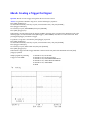
The Difference Between P-P Voltage Noise and Rms Noise
Current Overshoots Above the Current Limit Setting
Driving Inductive Loads
Remote Sensing
Floating the Output Above Ground
Series/Parallel Output Connections
Remote Inhibit Capability
Remote Inhibit is Pulled Low
Voltage Programming With an External Signal Source
Superimposing Noise on the Output
Synchronizing Output Turn-On and Turn-Off
Software Driver Information
Errors When Programming Over the GPIB
Readback is Intermittently Corrupted or Empty
3
4
5
6
7
8
9
11
12
13
14
15
16
17
18
19
20
21
22
23
24
25
26
27
28
29
30
31
603xA models
603xA: Secondary Address
603xA: Programming Language
32
33
6050A and 6060B models
605xA And 606xB: Electronic Loads in Series/Parallel
605xA And 606xB: Electronic Loads Below 3 Volts
605xA And 606xB: Electronic Load Power-On State
605xA And 606xB: Electronic Load Resistance Accuracy
605xA And 606xB: Electronic Load Constant Resistance Resolution
605xA And 606xB: Electronic Load Slew Rate
34
35
36
37
38
39
661xC and 663xB models
6612C: Compatibility With the 6612b
661xC And 663xB: Current Measurement Ranges
661xC And 663xB: Output Transition Time
663xB: Programmable Current Sinking
663xB: Compatibility With the "A" Version Units
40
41
42
43
44
668xA models
668xA: Sharing Current at Low Output in Auto-Parallel Mode
45
68xxA models
68xxA: Programming DC Output Voltage
68xxA: Creating a Trigger Out Signal
47
48
66000A models
66000A: Setting the Dwell Time in List Mode
49
E36xxA models
E36xxA: Rack Mounting
E36xxA: Setting the Line Voltage
E36xxA: Output Control Using Resistors
E36xxA: Making Adjustments With the Output Disabled
E36xxA: Remote Programming
E36xxA: Software Drivers
E36xxA: Internal Memory
E36xxA: Clearing the Contents of Power Supply Memory
E36xxA: Reading the Calibration Date
E36xxA: Instrument Repair Procedures
50
51
52
53
54
55
56
57
58
59
E3631A and E3632A models
E3631A and E3632A: Disabling the Control Knob
E3631A and E3632A: Output 'Off' State
60
61
E363xA and E364xA models
E363xA And E364xa: Compatibility With National Gpib I/F Card
E364xA: Fan Cooling
E364xA: Flashing Digit on the Display
E364xA: Settling Time
E364xA: Bench-Top/System Applications
E364xA: Returning The Unit to the State it was in Before Power was Removed
E364xA: Alternative Programming Language
62
63
64
65
66
67
68
Calibration Certificate
Question: Do all Power Products ship with a calibration certificate?
Answer: Criteria have been established to determine which products get or do not get a calibration certificate from
the factory. A product with a product number does not automatically qualify for a calibration certificate.
Products which meet the following 3 criteria will ship with a calibration certificate.
1. The product must have published specifications.
2. The product must be calibrated: specifications are checked and metrology is in place.
3. There is a likelihood the product will be recalibrated in the field at the recommended calibration intervals to
qualify for a calibration certificate.
Currently, four Power Products that are not shipped with a calibration certificate are the 6050A, 6051A, 66000A,
and the N3300A. Each of these is a mainframe power unit which houses separate plug-in modules. There are no
specifications to be checked on these products, and they do not have a recommended calibration interval in the field.
Therefore, there is no need for a calibration certificate for these products.
No Date on Calibration Certificate
Question: Why does Agilent currently ship Power Supplies with calibration certificates that are not dated?
Answer: The calibration date is dated on the Certificate of Calibration next to the signature of Electrical Inspector.
And the blank Calibration label (sticker) is stapled with the certificate of calibration.
There are no components used in Power Products which have a specific shelf life. Therefore, the calibration period
of this instrument begins on the date that the product is first put into service by the customer. The recommended
calibration interval for most Power Products is 12 months. Please check your User’s Guide to verify the specific
interval for your product. Once the product has been put into service, fill in the appropriate dates for recalibration on
the calibration label (sticker).
All Agilent Power Products will meet their published specifications for 1 year after the customer puts the product
into service.
Calibration Time Interval
Question: How long is the calibration time interval?
Answer: Agilent recommends 1 year as the calibration interval for all its power supplies.
Line Voltage Options
Question: How do I determine the correct line voltage option to order for my power supply?
Answer: Some power products use lots of power, far beyond the range of typical electronic products with which we
are familiar. This makes choosing the correct line voltage option more challenging. Also, power distribution systems,
regulations, and connection techniques vary greatly among geographic regions as a result of local electrical
standards. Many times, higher powered products require the help of a site electrician to provide the appropriate
power distribution, especially for products requiring 3-phase power.
Most Agilent power products have field-changeable line voltages; a few do not, and must be ordered with extra care
to avoid mistakes. However, even those that are field changeable may require more than changing the position of a
rear panel selector switch. In some cases, internal jumpers must be moved to accomplish the change. Thus, to assure
that your power product can be put into service with a minimum of effort on-site, it is important to use care in
ordering the product and in preparing the site.
The Power Products Catalog includes a section on selecting the correct line cord and line voltage for most
situations. Also, be sure to consult with your on-site electrician if there is any doubt about the correct method of
providing power to your product.
Line Cord Information
Question: Why doesn’t my power supply come with the right line cord?
Answer: Some power products use lots of power, far beyond the range of typical electronic products with which we
are familiar. This makes it difficult to identify and provide the correct line cord and plug in all situations. Many
times, higher powered products require the help of a site electrician to provide the appropriate power distribution. In
particular, 3-phase products are typically provided with an unterminated line cord, that is appropriate for the
destination country.
In other cases, the required line voltage and current dictates the line cord that is supplied. For example, the standard
voltage for the 2KW 667xA products is 230 Vac. These products can not be powered off a 120 Vac line because of
the high current required. Another example is the 601xA and 603xA families of autoranging power supplies. While
these can be powered from a 120 Vac circuit, they require currents in excess of 15 A, therefore they are shipped with
a line cord intended for operation on a 30 A 120 Vac circuit.
The Power Products Catalog includes a section on selecting the correct line cord and line voltage for these and
many other situations.
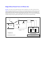
Single-Phase Power From a 3-Phase Line
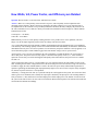
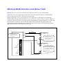
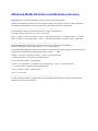
Question: Can I operate a power product that requires 220vac single-phase, from a 208vac 3-phase power line?
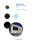
Answer: The figure below shows how you can draw close to the required voltage from a 3-phase power line. This
will work satisfactorily when the power line is reasonably close to nominal value. However, it is possible that the
power product may not be able to produce full power when the 208 Vac line is at the low end of its tolerance. For
example if the 208 Vac line were –10%, the resultant input voltage would be 187 Vac. This is below the minimum
acceptable voltage for the power product, which would be 191 Vac for a 220 Vac input line setting.
A
B
phase
phase
Earth
(Safety Ground)
208 Volts (typ)
120 Volts (typ)
N
C
L
phase
Note: Connections are made from
line to line.
Assume V(nominal) = 208 Vac
208 V @ 8% low = 191 V
208 V @ 12% high = 233 V
Rear of Instrument
(Instrument operates between 191 & 250 Vac)
Instrument requires an a.c.input voltage
instrument will not operate on a 120 Vac line
in the window 191 - 250 Vac
Switching and Linear Power Products
Question: Which power supplies are switchers, and which are linears?
Answer: Some people avoid switching power supplies because they have a poor reputation for performance,
specifically high p-p noise on the output, in addition to higher radiated and conducted EMI. However, Agilent
pioneered switching supplies such as the 6670 series which offered the performance of linears with the advantages of
switchers. Today, all Agilent power supplies offer very low p-p ripple and noise specifications, and very low radiated
and conducted EMI. The reputation for superior performance of products such as the Agilent 6670 and 6680 series is
well established. The 5kW 6680 series offers peak-peak noise as low as 10 mV and output programming response
times as low as 9 ms. In fact, Agilent switchers can be quieter than some linears! Poorly designed linears can have
commutating spikes when their bridge rectifier diodes turn off. These spikes occur at two times the power line
frequency, but the sharp edges radiate noise in the megahertz range and above. Agilent design engineers have gone
to a lot of effort to make both our linear and switching power supplies as noise-free as possible!
However, many switching supplies are still available from other manufacturers that do not offer this level of
performance. So as not to unfairly prejudice customers on the performance of these supplies, we have avoided
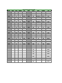
blatantly labeling them as switchers. The list on the following page indicates the type of each model of power supply
that Agilent has offered recently.
** Note: The "Hybrid" technology utilizes either primary or secondary 60 Hz SCR phase control switching followed
by a Linear regulator on the DC secondary side.
Switcher/Linear Type for Power Supplies
MODEL
6010A
6011A
6012B
6015A
6023A
6028A
6030A
6031A
6032A
6033A
6035A
6038A
6114A
6115A
6177C
6181C
6186C
6205C
6209B
6227B
6228B
6253A
6255A
6260B
6268B
6269B
6274B
6281A
6282A
6284A
6286A
6289A
6291A
6294A
WATTS
1000
1000
1000
1000
200
200
1000
1000
1000
200
1000
200
40
40
25
25
30
24
32
100
100
120
120
1000
120
2000
900
38
100
60
200
60
200
60
VOLTS
200
20
60
500
20
60
200
20
60
20
500
60
40
100
50
100
300
40/40
320
25/25
50/50
20/20
40/40
10
40
40
60
7.5
10
20
20
40
40
60
CURRENT
17
120
50
5
30
10
17
120
50
30
5
10
2
0.8
0.5
0.25
0.1
0.6/0.6
0.1
2-Feb
1-Jan
3-Mar
1.5/1.5
100
30
50
15
5
10
3
10
1.5
5
1
TYPE
Switcher
Switcher
Switcher
Switcher
Switcher
Switcher
Switcher
Switcher
Switcher
Switcher
Switcher
Switcher
Linear
Linear
Linear
Linear
Linear
Linear
Hybrid
Linear
Linear
Linear
Linear
Hybrid
Hybrid
Hybrid
Hybrid
Linear
Hybrid
Linear
Hybrid
Linear
Hybrid
Linear
MODEL
6612B
6621A
6622A
6623A
6624A
6625A
6626A
6627A
6628A
6629A
6632B
6633B
6634B
6641A
6642A
6643A
6644A
6645A
6651A
6652A
6653A
6654A
6655A
6671A
6672A
6673A
6674A
6675A
6680A
6681A
6682A
6683A
6684A
6612A
6296A
180
60
3
Linear
6813A
6299A
75
100
0.75
Linear
6814B
6541A
200
8
20
Linear
6834B
6542A
6543A
6544A
6545A
200
200
200
200
20
35
60
120
10
6
3.5
1.5
Linear
Linear
Linear
Linear
6825A
6826A
6827A
6841A
WATTS
40
160
160
160
160
75
150
160
100
200
100
100
100
200
200
200
200
200
500
500
500
500
500
2000
2000
2000
2000
2000
5000
5000
5000
5000
5000
750 VA/
1-ph
1750 VA/
1-ph
3000 VA/
1-ph
3000 VA/
3-ph
40
50
50
750 VA/
1-ph
VOLTS
20
20/20
50/50
20/20/50
20/20/50/50
50/50
50/50/50/50
50/50/50/50
50/50
50/50/50/50
20
50
100
100
20
35
60
120
8
20
35
60
120
8
20
35
60
120
5
8
21
32
40
300 Vac
CURRENT
2
10-Oct
4-Apr
37386
5/5/2/2
0.5/1
0.5/0.5/1/1
2/2/2/2
1-Jan
1/1/1/1
5
2
1
1
10
6
3.5
1.5
50
25
15
9
4
220
100
60
35
18
875
580
240
160
128
6.5
300 Vac
13
150/300 Vac
20/10
150/300 Vac
5-Oct
+/-20
+/-50
+/-100
300 Vac
+/-2
+/-1
+/-0.5
6.5
TYPE
Linear
Linear
Linear
Linear
Linear
Linear
Linear
Linear
Linear
Linear
Linear
Linear
Linear
Linear
Linear
Linear
Linear
Linear
Linear
Linear
Linear
Linear
Linear
Switcher
Switcher
Switcher
Switcher
Switcher
Switcher
Switcher
Switcher
Switcher
Switcher
Switcher-AC
Source
Switcher-AC
Source
Switcher-AC
Source
Switcher-AC
Source
Linear-Bipolar
Linear-Bipolar
Linear-Bipolar
Switcher-AC
Source
Cooling Requirements
Question: How much cooling do I need for my power supply?
Answer: Users frequently rack power supplies into an enclosure to supply power to some remotely located external
load. Under these conditions, to properly determine the cooling requirements, the systems integrator needs thermal
data from the manufacturer for the specific enclosure in question. This data is generally in the form of a curve which
relates the rise of the enclosure's internal air temperature to the amount of power (or BTU'S) dissipated within the
enclosure.
The difference between the maximum power demanded by the external load, and the ac power demanded by the
power supply to support the load's needs, is the power dumped into the internal air of the enclosure. Using this
number and data for the enclosure, the internal rise can be determined. The internal rise added to the external
ambient temperature will determine the temperature of the environment for the power supply. This must be within
the ratings of the product or premature failure will occur.
A valuable conversion factor between Watts and BTU's is listed below:
1 BTU/Hr = 0.293 Watt
Internal Memory
Question: How much volatile or non-volatile memory is available in Agilent Power Products?
Answer: The number of store/recall states for power products varies for different series.
DC power supply models:
6030A, 6031A, 6032A, 6033A, 6035A and 6038A have 16 volatile memory storage locations available to the user in
either Compatible or SCPI language mode. The user cannot pre-define the power on state.
6632A, 6633A and 6634A have no memory available to the user. The user cannot per-define the power on state.
66312A, 66332A, 6612B, 6632B, 6633B and 6634B have 4 non-volatile memory storage locations available to the
user in SCPI mode including one for power-on state. There is no memory available in COMPability mode. Consult
Users Guide or Programming Guide to pre-define the power on state.
664xA, 665xA, 667xA have 5 non-volatile memory storage locations available to the user in SCPI mode including
one for power-on state. There are 16 volatile memory locations available to the user in COMPatible mode. Consult
Users Guide or Programming Guide to pre-define the power on state.
668xA have 4 non-volatile memory storage locations available to the user in SCPI mode including one for power-on
state. There are 16 volatile memory storage locations available in COMPatible mode. Consult Users Guide or
Programming Guide to pre-define the power on state.
6610xA modules have 5 non-volatile memory storage locations available to the user including one for power-on
state. Consult the Users Guide to pre-define the power on state.
Electronic Loads:
The Electronic Load single input models 6060B and 6063B and module models 60501B, 60502B, 60503B, 60504B
and 60507B have 1 non-volatile and 5 volatile memory storage locations available to the user. Consult Programming
Guide to change power on state. The Electronic Load mainframe models 6050A and 6051A have no memory
available to the user.
AC Sources:
AC power source models 681xA, 681xB, 684xA have 16 non-volatile memory storage locations available to the user
including one for power-on state. Consult Users Guide or Programming guide to pre-define the power on state.
Constant Current Operating Mode
Question: How do I put the power supply in the constant current mode?
Answer: The power supply cannot be "put" into the constant current mode. The output settings of the power supply
combined with the ohmic value of the particular load determine whether or not the power supply is in constant
current.
For example: The power supply inherently resides in the constant voltage mode. If the output voltage were set to 24
volts and a 6Ω load were placed across the output terminals, Ohm's Law would require that 4 amps would flow
(24V/6Ω). This presumes that the constant current setting of the power supply were set to a value greater than 4
amps; lets say 5 amps. Now, if the 6Ω load were replaced by a 2Ω load, Ohm's Law would suggest that 12 amps
(24V/2Ω ) would flow. However, the power supply is set to go into constant current at 5 amps. Therefore, the actual
output voltage would be 10 volts (2Ω x 5A). The power supply will now remain in constant current for values of
load = 0≤ R < 4.8? . Once the ohmic value of the load becomes greater than 4.8Ω (24V/5A), the power supply will
again revert to constant voltage operation at the value of 24 volts.
Current Sinking
Question: Can Agilent power supplies sink current?
Answer: Yes! Sinking, or downprogramming, is the ability of a power supply to pull current into the positive power
terminal. Sinking is necessary to discharge the power supply's own output capacitor, or the capacitors that are part of
an external load.
Sinking is particularly important, for example, in printed circuit board test systems. The relays in test board systems
typically must be switched only when the power supplies have discharged to zero volts, to avoid arcing and burn-out
of the relay contacts. Sinking allows the power supply outputs to go to zero quickly, thus providing faster test times,
an important factor for reducing overall test cost.
The value of the sink current is fixed and is not programmable, with the exception of the 663xB Series, where sink
current is set to the same value that is programmed for source current.
In general, sinking is provided to improve a power supply's transition time from a higher to a lower constant voltage
operating level, and is not intended to be a steady-state operating condition.
Products
Current Sinking Capability
661x Series 40 Watt
60% of source current rating
6621A, '22A, '23A, '24A, '27A Multiple Output
110% of source current rating
6625A, '26A, '28A, '29A Precision Output
110% of source current rating
663x Series 100 Watt
110% of source current rating
603x Series Autorangers
50 W/actual output voltage in volts or
actual output voltage volts/0.05 ohms, whichever is less
664x Series 200 Watt
25% of source current rating
665x Series 500 Watt
20% of source current rating
667x Series 2000 Watt
50 W/actual output voltage in volts
or actual output voltage in volts/0.05 ohms, whichever is less
668x Series 5000 Watt
50 W/actual output voltage in volts
or actual output voltage in volts/0.05 ohms, whichever is less
Down Programming
Question: What is down programming?
Answer: When a power supply with current sink capability is programmed to a voltage level less than that actually
at the output terminals it will automatically begin to sink current. The downprogrammer can be thought of as an
internal load across the power supply's output terminals that helps bring the output voltage down quickly.
This is particularly useful in automated test of a device at several voltage or current levels, or in high volume testing.
The primary function of the down programmer is to discharge the power supply's output capacitor but in some cases
this feature may be used as a load to the device under test. The supply might be used to both charge and discharge a
device such as a capacitor or a battery.
Supplies vary in the level and other characteristics of current they sink. Some supplies such as the 603xA, 664xA and
665xA sink a fixed current equal to about 10% of their rated output current while the 667xA series sink a constant
power (as the output voltage falls the supply sinks more current). The 662xA series have fixed dual range sink
capability similar to their output ranges and the 663xA/B series supplies are programmable. See the Operating
manuals to determine the characteristics of each model.
The Difference Between Watts and VA
Question: Why are the required Watts and VA so different?
Answer: Watts is a scalar quantity which is frequently used to measure system efficiency. It is the energy supplied
by the utility company over a given period of time and is commonly referred to as power. Except for heavy industrial
users, the utility company only bills users for the watts consumed. Watts are directly convertible into mechanical
work or BTUs (British Thermal Units) of heat. Wasted power is paid for a second time in terms of additional loading
on the user's air-conditioning system. Mathematically, it is a scalar quantity resulting from the vector product of two
vector quantities (volts and amps). It is NOT the simple algebraic product of the rms volts times rms current.
VA on the other hand IS the scalar quantity resulting from multiplying the magnitudes (rms) of the vector quantities
(volts and amps). This resulting quantity will never be smaller than the watts demanded by an instrument.
Uninformed users incorrectly use VA to assess the device's over-all efficiency and power demands. VA is most
frequently and correctly used by electricians to determine proper ac mains conductor gage and circuit breaker sizing.
How Watts, VA, Power Factor, and Efficiency are Related
Question: How are Watts, VA, Power Factor, and Efficiency related?
Answer: "Watts" is a scalar quantity, often referred to as power, and is frequently used in conjunction with
measuring system efficiency. Watts is the energy supplied by the utility company over a given period of time to
accomplish work for the consumer. Except for heavy industrial consumers, the utility company only bills users for
the watts consumed (not VA). Watts are directly convertible into mechanical work (horsepower) or BTUs (British
Thermal Units) of heat.
1 Horsepower = 746 Watts;
1 BTU/Hr = 0.293 Watts
Mathematically, a watt is a scalar quantity resulting from the vector product of two vector quantities (volts and
amps). It is not the simple algebraic product of the rms voltage times the rms current.
"VA" on the other hand is the scalar quantity resulting from multiplying the rms magnitude of the vector quantities,
volts and amps. This resulting quantity will never be smaller than the watts demanded by an instrument. Uninformed
individuals incorrectly use VA to assess a product's over-all efficiency and power demands. Correctly applied, VA is
used to determine proper ac mains conductor gage and circuit breaker sizing as well as "power factor".
"Power factor" is, for a given set of conditions, the watts consumed by a product divided by the VA necessary to
deliver that power. The power factor will only equal 1.0 when the load is purely resistive; i.e., watts consumed
equals the VA necessary. In real life this happens infrequently. More times than not, the power factor is a number
less than 1.0.
As the load becomes more reactive, a greater number of VA is required to deliver the same number of watts to the
load. Assuming the rms mains voltage remains fixed, the decreased power factor necessitates a larger rms current be
available to supply the same nominal number of watts to the load. The power utility and distribution grid must be
capable of generating and distributing this disproportionately high level of current. This is why the utility companies
are desirous of power factors near 1.0 for products.
"Efficiency", is simply the work done by a system divided by the work supplied to the system. For an electrical load
under a given set of conditions, this is usually the output power divided by the input power. The resulting number is
always less than 1.0. The difference between the output power and the input power is the number of watts lost from
the system in the form of heat. Lost watts can be converted into BTU's/Hr and equates to the amount of heat which is
released into the ambient surroundings.
The Difference Between P-P Voltage Noise and RMS Noise
Question: What is the difference between voltage P-P noise and RMS noise specifications?
Answer: Both Vp-p and Vrms are measures for the unwanted ac components of a dc power supplies output. Peakto-peak noise is measured from the maximum positive point on the waveform to the most negative voltage point.
This measurement is particularly important for applications where noise spikes could be detrimental to accurate
measurements on a sensitive load, such as r.f. circuitry.
RMS is an abbreviation for root mean square, and it’s accurate measurement requires a true-RMS responding
voltmeter. This measurement is not an ideal representation of dc power supply noise, since fairly high output noise
spikes of short duration could be present in the ripple, and not appreciably increase the RMS value.
Current Overshoots Above the Current Limit Setting
Question: Why does the power supply allow transient current overshoots above the current limit setting?
Answer: Agilent power supplies can operate in either constant voltage (CV) or constant current (CC) over the rated
output voltage and current. However, most are designed as constant voltage sources. This means that these units turn
on in constant voltage mode. There is no command for constant current operation. Whether you set the current (Iset)
to 0 or any other value, the dc source operates in the CV mode first, and will generate maximum voltage set by
voltage (Vset) until the operating mode of the unit is determined by the voltage setting, the current setting, and the
load resistance. Thereafter, the power supply will automatically transition back and forth between CV and CC mode
as necessary based on changes in the load resistance, the voltage setting, or the current setting.
Furthermore, the transition from CV to CC is not instantaneous. The power supply’s internal control loop has a finite
slew rate characteristic, which introduces a time delay in mode crossover. Switching power supplies respond more
slowly (typically 100’s of milli-seconds) than linear supplies (typically 100’s of micro-seconds). During this
transition period, the current can exceed the current limit by a significant amount.
This should not be surprising. The output capacitor, present on every power supply, is outside the control loop, and
is capable of supplying very large currents into the load as a result of resistance changes. This type of situation is
possible with most power supplies to a greater or lesser extent. To prevent this characteristic from becoming a
problem, there are a few precautions you should observe.
First choose the smallest power supply that will reasonably do the job. If possible, use a linear rather than a switcher.
Choosing a larger supply than necessary may provide flexibility, but it also increase the potential for problems.
Next, don’t “hot switch” the device under test (DUT) onto a power supply output that is already at working voltage,
especially if the DUT represents a capacitive load. Instead, first program the power supply to 0.0amps, then connect
the DUT, then re-program the supply to the desired current limit.
Lastly, don’t turn the power supply output on with a sensitive load connected. The power supply will initially turn on
in the CV mode. The only way to turn the unit on in CC mode is by placing a short across the output and then
enabling or turning the output on, and finally removing the short.
Driving Inductive Loads
Question: How can I drive an inductive load or a large electro-magnet with a power supply?
Answer: One of the popular uses of Agilent power supplies is driving large magnets. Magnets are commonly used in
several industries including nuclear fusion research and magnetic resonance imaging. However, there are a couple of
problems that can arise in these applications.
Power supply oscillation can occur when driving an inductive load or magnet.
It may be difficult to ramp the current through the magnet fast enough (especially withcryogenic magnets).
Since a magnet is basically a large inductor, the power supply must be stable when driving a large inductive load.
Inductive loads present no stability problems in the CV mode, however, in the CC mode a parallel resonant network
is formed by the inductance of the load and the output capacitance of the power supply. This can cause ringing, or
even oscillation at a frequency given by the formula:
Frequency of oscillation = 1 / [(2)(3.1416)(LC)^.5]
Also, the rate of current flow through a magnet is determined by the formula: di/dt = L/V
The larger the magnet, the higher the voltage must be to drive it at a given ramp rate. The power supplies maximum
voltage ratings may be insufficient for these applications. In other cases, a higher current may be needed than one
power supply can provide. Paralleling power supplies to get more current for driving magnets increases the
possibility of oscillation problems, which can destroy the DUT (Device Under Test).
The solution to these problems is to use a power supply that has stability for inductive loads either built-in, or
provided as a special option. Here are some examples:
6680A and 6681A (5 kW): have internal stabilization for loads up to 7 Henrys
6010A*, 6011A, 6012B*, 6030A, 6031A, 6632A and 6038A* have special options available:
Option J01 - stabilization for loads up to 10 Henrys
Option J02 - stabilization for loads of 10 to 25 Henrys ( * = J02 not available for these supplies)
For driving inductive loads when using the 664x, 665x, 667x and 668x supplies, refer to their Operating Manuals to
understand power supply stability. Contact your local Sales Office for information about specials for these and/or
other Agilent power supplies.
Remote Sensing
Question: How can I offset the voltage drop caused by long cable lengths from my dc power supply to the device
under test (DUT)? What is remote (error) sensing? When is it needed?
Answer: Normally, Agilent power supplies are delivered configured to deliver their full specs at the output
terminals. In some application, where long lead lengths to the DUT are unavoidable, the regulation of the power
supply at the DUT can be significantly improved by using remote sensing. The sense leads effectively connect the
inputs to the power supply control loop directly to the DUT. Since there is negligible current in these sense leads, the
exact voltage at the DUT is communicated back to the power supply. Now any resistance in the load leads is
essentially brought inside the power supply control loop, and is effectively “eliminated”.
The amount of drop in the load leads that the sense leads can correct for is limited. In general, most Agilent dc power
supplies can handle up to 2 volts in each load lead. Some power supplies are available which can drop up to half the
rated output in each lead. Of course, the total drop in the load leads subtracts from the rated voltage available for the
DUT. Refer to the Power Products Catalog for the remote sensing specifications for the power supply of interest.
PROCEDURE:
For the 661xB/C, 663xB, 664xA, 665xA, Electronic Loads, 66111A, 66311A, 66312A, 66332A, 6610xA, E3614A,
E3615A, E3616A, E3617A:
Make the sense wire connections (+S to +; -S to the -)
Ensure that the Remote/Local switch on the back of the unit is set to “Remote”
Note: front panel binding posts do not have remote sense capability
For the 667xA, 668xA, E3632A (no Remote/Local switch):
Remove the jumpers connecting +S and +, and connecting -S and Make the sense wire connections (+S to +; -S to the -)
For 681xA, 6814B, 6834B and 6843A ac sources (no Remote/Local switch):
ALWAYS make the sense wire connections (+S to +; -S to the -)
Also, in applications requiring relays, the 59510A/11A Relays automatically switch and sequence both load and
sense leads. When used with Agilent system power supplies that have been configured appropriately, the relays can
be controlled through the power supply GPIB port. Please refer to the Operating Manuals elsewhere on this website
for more complete information on remote sensing .
Floating the Output Above Ground
Question: Can I “float” the power supply above ground?
Answer: The chassis of the power product must always be referenced to earth ground, for safety reasons. However,
the output is isolated and may be connected to a point other than ground. It is most common for the output to be
connected to circuit common, but in some applications it is advantageous to have the power supply output referenced
to some voltage above (or below) ground.
For most Agilent Power Products, the maximum floating voltage is +/- 240 volts from chassis ground. However, the
following products have different isolation voltages as indicated:
6015A/6035A: +/-550 volts
68xxA: 300 vrms
66312A: +/- 50 volts
E3631A 6 volt output: +/-25 volts
Floating a power supply can represent a hazard to people and equipment. Be aware of the following considerations
when floating a power product.
Digital I/O ports are referenced to ground, regardless of where the power product output is referenced.
A grounded analog programming source may short out the current sense resistor causing uncontrolled output currents
or blown tracks on the power supply circuit board. Be sure the programming source is fully isolated. Think through
all connections carefully.
Multiple grounds in the system can cause ground loops resulting in extra noise, and possible dc measurement errors.
Be sure to consult the Application Information section of the Power Products Catalog for more information on
these and other applications.
Series/Parallel Output Connections
Question: Can I connect dc power supplies in series or in parallel to obtain higher currents or voltages?
Answer: Yes, in many cases this can be done, however there are some specific cautions. The resultant voltage for
series connections cannot exceed the maximum floating voltage allowed for any of the component power supplies.
While this is typically +/-240 volts dc, there are some supplies as low as +/-25 volts dc, and others as high as +/-550
volts dc. For best results, only supplies of equal output voltage ratings should be paralleled and only supplies of
equal current ratings should be placed in series.
Some Agilent dc power supplies have the capability for auto-parallel operation, which increases the convenience of
controlling the resultant configuration. In this case, only one unit has to be controlled (manually or by computer
control) to take advantage of the full power of all supplies. For more information, refer to the Power Products
Catalog.
Remote Inhibit Capability
Question: I want to put a microswitch on the safety cover so that lifting the cover will program my ATE power
supplies to zero volts. Do Agilent power supplies have this capability?
Answer: Yes, all of the GPIB programmable supplies in the 603xA, 664xA, 665xA, 667xA and 668xA series as
well as the 68xxA series ac sources have this capability called remote inhibit built-in at no extra cost. Remote Inhibit
is available as an option at extra cost on the 662xA and 663xA series. A contact closure or TTL low signal applied to
the INH line programs the output of the supply to zero volts. The power supply can also be programmed to generate
a service request (SRQ) via the GPIB in the event that the INH line is pulled low.
Remote Inhibit is Pulled Low
Question: Why is INH pulled low to disable the 66xxA power supply or 68xxA ac source?
Answer: It might appear more logical to have a contact opening represent the disabled state in a "fail-safe" manner
than contact closure. That way, the source would go into the disabled state in the event that the connector falls off or
a wire breaks, or a micro-switch opens. However, the disadvantage of this approach is that it complicates
communication between multiple supplies in a system.
Pulling the INH line low to disable the source makes it possible to "wire-or" together the FLT (fault) output signals
for a group of power supplies and ac sources. Thus, an INH input signal (remote inhibit) to any of the units can be
used to shut down all others in the system. Internal circuitry latches the INH line low until, keeping all supplies
disables until they are deliberately reset.
An additional reason for choosing the low state to disable the output is that it simplifies normal operation for users
who do not need to use the disable capability. Thus, those users who are not using this capability do not have to
remember to connect the required jumper wire, or plug in a connector with the shorting jumper. Otherwise, where a
positive connection is required to establish normal operation, users frequently mistakenly conclude that the unit has
failed, and that the output is dead.
Voltage Programming With an External Signal Source
Question: Can Agilent power supplies be programmed from 0 to full output voltage using a 0 to 10V signal source?
Answer: Yes, many Agilent power supplies feature remote voltage programming or analog programming capability.
However, there is a potential danger in analog programming any power supply, especially a high voltage supply. If
the 0 to 10 V programming source is a typical, non-isolated, low-cost, digital-to-analog converter (DAC), it is
probably grounded through its digital inputs and/or through the computer’s internal power supplies, which are
grounded through the computer’s power cord. It’s easy to overlook this, and the mistake can be very expensive.
If the DAC is non-isolated, (or isolated only up to 42 V above ground), and one of the output terminals of the power
supply is grounded, either directly or through the UUT, the output capacitor of the power supply can discharge
through the computer backplane, motherboard, and the I/O common through the computer power cord ground. The
resulting high current may even last long enough to vaporize the thin ground tracks on some or all of the printed
circuit boards in the PC.
Be sure the programming source is electrically isolated, is operated from isolated power supplies, and is rated for
floating voltages up to the full output voltage of the programmed supply. This is necessary so no one is hurt, and no
equipment is damaged, no matter which output terminal of the power supply or UUT is grounded.
Refer to the topic on Constant Voltage Programming with Variable Voltage Gain in the application section of the
Power Products Catalog for more detailed information.
Superimposing Noise On the Output
Question: How can I superimpose noise on the output of a dc power supply?
Answer: Agilent power supplies are designed to have the lowest noise that is practically possible. For some
application it is desirable to simulate the effect of noise on the output, for example to test system immunity to power
line disturbances. Many Agilent power supplies have an analog programming input which can be used to modulate
the output with a signal typically 0.0 to 5.0 volts. This can provide a satisfactory solution for some cases, however,
the bandwidth is limited with this approach, generally to less than 10KHz.
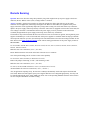
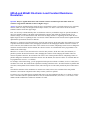
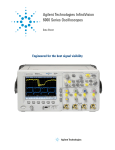
For applications where it is necessary to simulate higher frequency noise, the solution involves using a current
coupling transformer in series with the output. The desired signal, presumably from a suitable signal generator, is
connected to primary of the transformer (refer to the figure below). Information on the specifications of a suitable
transformer are included. Note that for some applications a wideband power amplifier may be necessary to avoid
excessive loading on the noise source.
NOTES: Core on transformer is critical to
performance of system.
Low noise, Linear Power Supply
E/I steel or tape wound: 5Hz - 20Kz noise
Operated in CONSTANT VOLTAGE
Tape wound toroid: 20Kz - 120Khz noise
Powered Iron/Ferrite: 120Khz - 300Khz noise
+
Ferrite: 300Khz - 1Mhz noise
-
Air core: >1Mhz noise
Under some conditions a wideband power amplifier
may be required between the noise source and
Noise
the current coupling transformer.
Source
500 - 1000 turns
+
1 turn
DUT
-
Synchronizing Output Turn-On and Turn-Off
Question: How can I synchronize different power supply outputs to turn on and off at the same time?
Answer: This can be a challenging problem because the products that could potentially be grouped together have
been designed over a period of 20 years. The availability of “hooks and handles” varies somewhat by series of
products. Also, there are some inherent limits as to how “simultaneously” products can react due to different power
supply topologies have different slew rates (i.e. the speed with which the output can change). Linear supplies
typically have slew rates in the 100’s of microseconds, while switching supplies respond in 100’s of milliseconds.
In the most general case, the majority of Agilent power products offer RI/DFI (remote inhibit/discrete fault
interrupt). This feature can be used to turn products off simultaneously, either as a result of a specific power supply
fault, using the DFI signal, or due to some external event, by pulling the RI contact low. Refer to the manual for your
product for additional information on how to accomplish this. On most products, the RI contact is a latching
function. Therefore to turn the products on, once RI has been activated, RI needs to be converted to non-latching.
While this capability is standard on the 661xA and 663xB products, it requires a special option, S50, on other series.
Contact your Field Engineer to find out about the availability of this option for your product. External components
such as relays, or FET switches are also required to control multiple power supplies.
For groups of products which all have SCPI command language, the group execute trigger (GET) command can be
used. However, timing accuracy is limited by command processing time which can be up to 50 milliseconds.
Furthermore, this approach cannot be used with power products that offer sub-addressing. See the programming
guide for your product family (available elsewhere on this website) for more information on <*TRG> and
commands. Also, refer to “IEEE Standard Codes, Formats, Protocols, and Common Commands”, IEEE STD 488.21992 available from the IEEE.
One more alternative is available for systems composed of 66000 modular power system modules and 68xxB ac
sources. These products have expanded feature sets, which include “list and trigger” capabilities. These features
make it easier to synchronize or sequence power products. For more information, refer to Product Notes 5091-2497
and 5963-7044 for 66000 and 68xxA products respectively, which can be found using the search button in the upper
left corner of this website.
Software Driver Information
Question: Where can I find a software driver for my Agilent power product?
Answer: The VXI plug&play drivers can be found at <
http://www.tm.agilent.com/tmo/software/English/PowerSupplyDrivers.html >. Copy this URL into your
browser. From this page you may select the driver for the specific product of interest.
The plug&play drivers found here will work in the LabView environment, however, if you are also using a National
Instruments GPIB card, you will need the VISA library. This VISA library must be installed with the plug&play
driver, and it can be located on National Instruments website. Copy this URL into your browser: <
ftp://ftp.natinst.com/support/visa/drivers/win32/2.0/ >. Then select the file named visa20.zip.
National Instruments also has a library of drivers for many different products, both those developed by National
Instruments, and those contributed by third parties. Note: These drivers are not supported by Agilent. The library
can be found at < http://www.natinst.com/idnet/idl.htm >.
Errors When Programming Over the GPIB
Question: Why doesn’t my system power supply accept commands over the GPIB? Why do I keep getting an error
when I try to communicate with my system power supply over the GPIB?
Answer: If you are getting either error 11 or error 113 when you try to send GPIB commands to your system supply,
it may be that you are using the wrong command language. Many Agilent power supplies have two different sets of
programmable commands, especially if they were introduced prior to 1989 when SCPI (Standard Commands for
Programmable Instruments) became available. The reason for this feature is to offer customers the choice of
preserving compatibility with existing software programs written for these products some time ago, or allowing new
software programs to be written using the industry standard SCPI codes and formats. Because the supplies can accept
commands only in the language they are set for, sending a command in the “inactive” language will cause an error.
When shipped from the factory, the default language differs depending on the model, as follows :
Compatibility mode for: 6632B, 6633B, 6634B, 603xA
SCPI mode for : 6631B, 661xB, 664xA, 665xA, 667xA, 668xA, 6631xA, 66332A
The procedure for changing command language mode varies depending on the specific product involved. In general,
to change to a different command language mode, enter the following command:
To change to the SCPI command language:
If the customer has: 661xB, 663xxA, 663xB
Enter the command: SYST:LANG SCPI
If the customer has: 664xA, 665xA, 667xA, 668xA, 603xA
Enter the command: SYST:LANG TMSL
To change to the compatibility language:
For all products
Enter the command: SYST:LANG COMP
Note that the current active language setting is stored in non-volatile memory. This mode is retained when the power
supply is shut off. When the power supply is subsequently powered on, it will be set for whichever language was
used last.
For more complete information on changing the command language mode, please refer to the operating manual for
your product. For the 603xA Series products, see also the FAQ entitled: “603xA: How do I change the programming
language?”.
Readback is Intermittently Corrupted or Empty
Question: Why is the readback from my power supply intermittently corrupted or empty?
Answer: This problem frequently occurs on the second of two queries. While this is most common with the 662xA
family of supplies, it can occur on other system power products, but generally only if they are being used in
compatible language mode. This may occur with a recent purchased supply while others of the same type which have
been in the system for some time operate satisfactorily.
This problem arises from an internal difference in GPIB chips from certain suppliers. The problem is that the newer
design GPIB chip may cause a line feed character to remain in the output buffer after the readback query. Normally,
the power product firmware will clear the leftover bit out of the buffer when it prepares a response to the next query.
However, if the second query comes in too quickly, the leftover “line feed” is returned and may appear as a null
string.
For a temporary workaround, make sure every query is terminated with a or EOI . Make sure that all characters in the
buffer are read back before initiating another query. To accomplish this, insert a wait statement of at least 200 ms
after any query before beginning to read back the characters.
For products which display this problem, there is a firmware fix that can be implemented at the Service Center.
Contact your local Sales Office or Call Center, for more information. Click on the "Assistance" button in the upper
left corner to obtain the number of the office nearest you.
603xA: Secondary Address
Question: How can you change or view the secondary address in the 6030A, 6031A, 6032A, 6033A, 6035A, or
6038A power supplies?
Answer: These products have been retrofitted with SCPI language capability, in addition to the original or
compatibility mode. Secondary addressing of these products is only available in SCPI mode. These products are
shipped from the factory in the COMPatible Language Mode with their hardware address set to "Adr 5". Secondary
addressing is NOT available in COMPatible mode.
To change the programming language to SCPI Mode send string "SYST:LANGTMSL" using an GPIB controller. In
the SCPI Mode, either by cycling the ac line or by holding in the [ LCL ] front panel button. The display will first
show "Adr 5", the primary address, for 2 seconds, then "SEC xxx" the secondary address until the [ LCL ] button is
released. The primary Address is set using the rear panel address switch. All instruments connected directly to the
GPIB interface must have a unique primary address. With the [ LCL ] button depressed, and the display showing
"SEC xxx", the rotary pulse generator can be used to change the xxx portion from "---" (null) to an integer number
between "0" and "15".
A display of "Adr 5" followed by "SEC ---" designates the the instrument to be a stand alone instrument and must be
talked to by using address 705. A display of "Adr 5" followed by "SEC 0" designates the instrument as the direct
instrument in a possible chain of instruments and must be talked to by using address 70500. (This instrument must be
the instrument connected to the controller via the GPIB cable). In either case ("SEC ---", or "SEC 0"), the display
"Adr 5" is still viewable when the ac power is cycled or when the [ LCL ] button is initially depressed. A display of
"Adr ---", primary address a null, followed by "SEC 1","SEC 2", or "SEC nn" when the ac line is cycled or the [
LCL ] button is depressed is a linked instrument. Instruments where the "SEC nn" is a number = or > 1 are linked
instruments, and can only be talked to by a direct instrument. Linked instruments can never be talked to directly from
the controller.
If a unit is in the SLAVE or LINK mode and you wish to convert it to a MASTER, follow this procedure:
Set the GPIB address to a reserved address "31".
Turn the unit off, then turn it on again.
Set the address to "5" or any valid address number.
Cycle the power again and the unit will now be set as a MASTER.
NOTE: The choice of programming language is stored in the instrument's nonvolatile ROM and remains the
language of choice until deliberately changed by the user. Reference the 603xA family Operating Manual, p/n 59593342. Errors reported as "8" or "-113" are characteristic of using a programming syntax which is inconsistent with
the product's setting/expectations.
603xA: Programming Language
Question: How do you change the programming language expected by the the 6030A, 6031A, 6032A, 6033A,
6035A, or 6038A power supplies?
Answer: These products are shipped from the factory in their native language (called Compatible Language Mode)
with their hardware address set to "Adr 5". The programming language can only be changed to SCPI Mode via a
controller by sending the string "SYST:LANGTMSL". The programming language can be returned to COMPatible
language mode via a controller by sending string "SYST:LANGCOMP" or by Setting the rear panel address switch
to "31". Cycle the AC power and observe that the display will read "ERR 8". Reset the rear panel address switch to
"5" Cycle the AC power again and observe that the display will read "Adr 5". The instrument is now in its native
(COMPatible) language.
Here’s how to determine which language the power supply is set to. From a controller send command string
"SYST:LANG?" Alternatively, from the front panel press and hold [ LCL ] button. (For the following, x is a number
greater than or equal to 1). If the front panel display reads "Adr x" for 2 seconds, then returns to a volt/amp meter
display the instrument is in COMPatible language mode. If the front panel display reads "Adr x", then "SEC xxx",
the instrument is in SCPI language mode."SEC xx" is a secondary address available only in the SCPI mode.
Note that the choice of programming language is stored in the instrument's nonvolatile memory and remains the
language of choice until deliberately changed by the user. Refer to the 603xA Family Operating Manual, p/n 59593342 Appendix C, paragraph titled LANGUAGE SWITCHING.
605xA and 606xB: Electronic Loads in Series/Parallel
Question: Can I use Agilent Electronic Loads in series and in parallel?
Answer: Agilent electronic loads ARE designed to be operated in parallel for more current, but NOT in series for
more voltage. Loads are fully protected against damage from current overloads, but will be damaged by voltage
above the maximum voltage rating.
605xA and 606xB: Electronic Loads Below 3 Volts
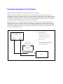
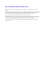
Question: Is there a way I can use an 606xB or 605xA Electronic load below 3 volts without derating?
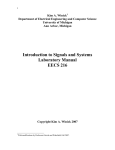
Answer: Yes. Use a boost supply in series with the UUT. The load will now meet all its specs with no derating,
because it always operates above 3 volts (refer to the figure below).
The boost supply can be a low-cost fixed output 3 V or 5 V supply with a current rating at least as high as the
maximum peak load current needed. The 6641A (8 V, 20 A), 6651A (8 V, 50 A), 6671A (8 V, 220 A), or 6681A (8
V, 580 A) are all excellent choices. The voltage setting of a programmable boost supply should be set to 3 volts, and
the current limit set to full scale. Select a boost power supply with low peak-peak (p-p) ripple and noise. The
constant current load will compensate for low frequency p-p ripple and noise below a few kHz, but high frequency
ripple and noise from the boost will appear across the UUT.
I LOAD
+
Electronic Load
+
+S
Operated in constant voltage
or constant current
-
DC Boost
Supply
Boost supply operates in
-S
constant voltage at ~3.5 volts;
-
must be able to handle UUT's
I(max) discharge current
+S
-S
IM
VM
+
UUT
+S
A COM
Unit under test must be attached
EXT PRG
to the negative terminal of the
Load for the remote voltage sensing
A5
to function correctly.
FLT
PORT
D COM
-S
-
605xA and 606xB: Electronic Load Power-On State
Question: When powered on, what is the wake-up voltage and current setting of the 606xB and the modules
installed in the Agilent 605xB Series electronic loads?
Answer: The 606xB and the modules installed in the 605xA mainframe have 7 user-definable recall states which
allow saving the settings of the load for later recall. One of these states, location 0 is non-volatile; this is called the
wake-up state. The 606xB and the modules installed in the 605xA will be set to the state stored in location 0 at
power turn-on. If no state has been saved to location 0, then it will still contain the factory-default state. The factory
default state normally would be 0 V and 0 A. See *SAV in Programming Manual 06060-90005.
605xA and 606xB: Electronic Load Resistance Accuracy
Question: How do I determine Resistance Accuracy in the Electronic Load Family?
Answer: The 6060B specifications will be used for this example. The resistance accuracy of other models can be
determined by substituting the accuracy specifications of the other model in the example below.
____________________________________________________________
For the 6060B low range and a desired resistance of 1 ohm, the calculations are:
Low range accuracy specification is +/-0.8% + 0.008 ohms
Ohms + [( Ohms * accuracy percentage ) + offset ] = high specification point 1+((1*0.008)+0.008) = 1.016 ohms
Ohms - [( Ohms * accuracy percentage ) + offset ] = low specification point 1-[(1*0.008)+0.008] = 0.984 ohms
____________________________________________________________
For the 6060B middle and high ranges, and a desired resistance of 50 ohms the calculations are:
Middle and high range accuracy specification is +/-0.3% + 0.008 Seimens.
The middle and high range specifications are in Seimens so the ohmic value must be changed to Seimens before the
calculations are performed, then changed back to ohms. Seimens = 1 / Ohms
Seimens + [( Seimens * accuracy percentage ) + offset ] = high Seimens point
1 / high Seimens point = low resistance specification point
1/50+((1/50*0.003)+0.008) = 0.028 Seimens
1/0.028 = 35.6 ohmsSeimens - [( Seimens * accuracy percentage ) + offset ] = low Seimens point
1 / low Seimens point = high resistance specification point
1/50-[(1/50*0.003)+0.008] = 0.0119 Seimens
1/0.0119 = 83.75 ohms
____________________________________________________________
For more detailed information, read Appendix A in the 606xB Operating Manual or 605xA Operating Manual,
which can be found on this CD-ROM.
605xA and 606xB: Electronic Load Constant Resistance
Resolution
Question: Why are Agilent Electronic Loads constant resistance resolution speced in ohms on the low
resistance range, but in mSiemens on the two higher ranges?
Answer: In general, Agilent Electronic Loads are not a conventional "resistor". The loads consist of IC's, capacitors,
resistors, FETs, etc. They were designed with two major circuits, a cv and cc circuit. These circuits are used to
simulate resistance on the two upper ranges.
First, it is necessary to understand why there is a difference in the way in which the ranges are specified (mohms or
mS). The constant resistance (CR) mode in the load actually operates using either the constant current (CC) or
constant voltage (CV) circuits inside the load. The lowest CR range uses the CV regulating circuits, while the two
higher ranges use the CC regulating circuits. It is because of these differences in the circuits used to regulate the load
input that the specifications need to be different.
When the CV circuits are used, the load can be viewed as many resistors, all the same value (the resolution), in series
to produce the desired resistance. Then, changing the resistance is like changing the number of discrete resistors in
series. Therefore, the resolution is the value of one of these series resistors, and putting resistors in series changes the
resistance measured in ohms. For the 60501B, the "discrete resistor" or resolution that can be programmed is 0.54
mohms in the 2 ohm range.
When the CC circuits are used, the load can be viewed as many resistors, all the same value (the resolution), in
parallel to produce the desired resistance. Then, changing the resistance is like changing the number of discrete
resistors in parallel. Therefore, the resolution is the value of one of these parallel resistors, and putting resistors in
parallel changes the conductance measured in siemens. For the 60501B, the "discrete resistor" or resolution that can
be programmed is 0.14 mS (=7.14 kohms).
For example, in the 2 kohm range, you can program the load input from 2 ohms to 2 kohms (0.5 S to 0.5 mS) with a
resolution of 0.14 mS. This would be the equivalent of starting with about 3568 7.143 kohm resistors in parallel with
each other, and in parallel with a 2 kohm resistor, and removing one at a time until you had only the 2 kohm resistor
left.
Note that the resolution of the conductance is constant at 0.14 mS, however, the resolution of the total parallel
resistance is not constant. It depends on how many resistors you have in parallel.
If you have two 7.143 kohm resistors in parallel and remove one, the resolution looks like 3571.5 ohms. If you have
3568 7.143 kohm resistors in parallel and remove one, the resolution looks like (7143/3567) - (7143/3568) = 0.561
mohms. But the conductance resolution is constant at 0.14 mS.
605xA and 606xB: Electronic Load Slew Rate
Question: What are the units used when setting the slew rate on the electronic loads?
Answer: When setting the slew rate from the front panel of the load, the units used are A/us. When setting the slew
rate over the GPIB, the units used are also A/s.
The range of slew rate that can be programmed varies depending on which output range (high or low input current),
and the model. As an example for the 6060B, on the low range (0-6A), slew rate can be programmed from 1A/ms
(0.001A/us) to 5A/us. On the high range (0-60A), slew rate can be programmed from 0.1A/ms (0.0001A/us) to
0.5A/us. The ranges of slew rate for all electronic load products can be found in the Supplemental Characteristics
section of the electronic load pages of the Power Products Catalog.
6612C: Compatibility With the 6612B
Question: Does the 6612C have the same programming language as the 6612B version, SCPI or VXI plug&play
drivers? Will it interface to other products? How compatible are these?
Answer: The short answer is yes! All of the models in this family (661xC) have two command sets: SCPI; and
Compatibility (663xA-type). The language format can be changed either by s/w command or from the front panel.
When the unit is turned off, the current language mode is stored in non-volatile memory. As a result, the unit will
wake up in whatever language was used last. This makes it easy to replace a B-version with the new C-version. The
same application program that was used with the B-version will work for the C-version.
661xC and 663xB: Current Measurement Ranges
Question: Do the 661xC and 663xB Series power supplies have more than one current measurement range? What is
the current measurement resolution? How do I switch between them?
Answer: Yes, these models feature TWO 16-bit current measurement ranges. The high range covers the full output,
with an LSB ranging from approximately 20 uA for 1A output to 436 uA for the 10A output.
Model
6611C
6612C
6613C
6614C
6631B
6632B
6633B
6634B
Max Current
5A
2A
1A
0.5 A
10 A
5A
2A
1A
Resolution
213 uA
74 uA
37 uA
20 uA
436 uA
213 uA
74 uA
20 uA
All models have a low range of 20.0 mA full scale, with an LSB of 0.6 uA. You can select either the high or low
range, or autoranging between the two. With autoranging, range switching is triggered whenever the current crosses
above/below 20.0 mA.
661xC and 663xB: Output Transition Time
Question: How fast can the 661xC and 663xB Series supplies respond to a command and generate a full scale
output?
Answer: The output transition time is comprised of two parts: command processing time (before the output starts to
change voltage), and the output programming response time (essentially the time it takes the output to go from 10%
of the voltage to 90%). Adding both figures will give a good estimate of the output transition time.
For both series of products, the command processing time has been reduced to <4ms.
The 663xB Series products have two operating modes, with a fast/normal mode switch on the rear panel. In the fast
mode, the output can slew from 10% to 90% within 400 us. In the normal mode the output slews in 2 ms. Note, use
of the fast mode will degrade noise performance somewhat (from 3 mV to 10 mV on the 6632B).
The 661xC models do not offer a fast/normal mode switch, however their output programming response time is
approximately 2 ms.
663xB: Programmable Current Sinking
Question: Can the current sinking limit be programmed on Agilent power supplies?
Answer: In general, current sinking is a fixed value at some percentage of the full scale current output.
However, there is an exception for one series of Agilent power supplies. On the 663xB series, the
maximum negative current tracks the value programmed for the positive current limit. This capability
allows the 663xB units to function as a constant current load in some applications, such as battery
cycling and test.
663xB: Compatibility With the "A" Version Units
Question: Do the 6632B, 6633B and 6634B have the same programming language as the A version, SCPI or VXI
plug&play drivers? Will it interface to other products? How compatible are these?
Answer: All of the models in this family have two command sets: SCPI; and Compatibility (663xA-type). The
language format can be changed either by s/w command or from the front panel. When the unit is turned off, the
current language mode is stored in non-volatile memory. As a result, the unit will wake up in whatever language was
used last. This makes it easy to replace an A-version 663x Series with the B-version 663x Series. Software written
for the A-version will work with the B-version if the B-version’s language format is set for Compatibility mode.
668xA: Sharing Current at Low Output in Auto-Parallel Mode
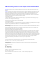
Question: Why don't my 668xA 5 kW power supplies share current at low output current when operated in autoparallel?
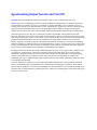
Answer: It's normal. They will share current at full load. Here's a complete explanation. Using 668xA Series power
supplies in auto-parallel, a maximum of five 668xA Series power supplies, with the same model number, may be
configured for auto-parallel operation. The 668xA power supplies were designed with a deliberate external
programming offset so the master will output current before the slaves output current. Therefore, slave(s) supplies
will always sink current when low output current values are desired.
Auto-parallel procedure:
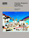
Connect the 668xA power supplies with Im from the master going to +Ip of each slave and comP going to -Ip of
each slave (refer to the figure on the next page).
Each load lead (wire) should be same wire gauge and length.
Turn on all power supplies.
Program each slave supply for zero output current either by pressing [CURRENT] [0] [ENTER] from the front panel
keypad or sending the command "CURR:LEV 0" via the GPIB. See note 2 and 3.
Program each slave supply's output voltage to a value at least 2 volts greater than the programmed output voltage of
the master supply.
Program the master supply's output current to one-half the total output current if there is one slave supply or onethird the total output current if there are two slave supplies.
Enable all power supplies by pressing [Output On/Off] key.
Increase the master supplies output voltage. At low output currents the slave(s) will sink current. This is normal. At
low output current the master will be supplying all the load current and sink current to the slave(s). At maximum
output current each supply will be delivering an equal amount of current. It is normal when operating at less than
maximum current to have unequal current sharing between the master and slave supplies. The master supply provides
more current at low output currents but current sharing will become equal when they reach maximum output current.
If remote sensing, only the master supply +S/-S lines are connected remotely. The slave supplies should be
connected for local sensing, connected at the rear of their respective output terminals.
Notes:
The current division between the master and slave(s) can be determined from the following formula:
Iout = Im [ 1 + Ns ( 1 + 0.127V / 5V ) ] - Ns Ifs ( 0.127V/ 5V )
The amount of current the master must output before the slave(s) outputs current can be determined from the
following formula.
Ns * Ifs ( 0.127V / 5V )
where
Im = master current
Ns = number of slaves
Ifs = full scale current
Example: 1 master 2 slaves Model hp6680A 5V 875A
Iout = Im ( 3.0508 ) - 44.4A
Master current limit must be set above 44.4A / 3.0508 = 14.55A to obtain any output current.
For no-load condition:
Master current = 14.55A
Each slave current = -14.55A / 2 = -7.28A
Iout = 0A
All 668xA power supplies have an output current programmed at ac power-on. The default current value
programmed at power-on can be found in table 3-1 of Programming Guide 5960-5597. See *RST and *SAV in the
programming guide to change the power-on current value.
A current programmed via the rear panel +Ip / -Ip inputs will be summed with a current programmed via the front
panel keypad or GPIB. When programming slave supplies via the rear panel +Ip / -Ip inputs all slave supply current
programming values must be zero ( 0 ).
Q Analog Connector
R Slave Supply
S Master Supply
TProgram only the master. Set slave output and OVP voltage slightly higher than the master to ensure that slave stays in
CC mode
U Load
V Load Connection
A Only local sensing permitted
B Connect for remote sensing (optional)
68xxA: Programming DC Output Voltage
Question: How do I program a DC voltage from an AC power source?
Answer: DC voltage can only be programmed from AC source models 6811A, 6811B, 6812A, 6812B, 6813A,
6813B, 6841A and 6842A. To program a DC voltage perform the following steps using the front panel keypad.
Press [ Shift ] key then [ Output ] key. Display will read "OUTP:COUP AC".
Press down triangle on function keypad once, display reads "*RST". press [ Enter ]. AC power source is now in a
known factory default power on state.
The right side of the front panel display should now be: METER This means the metering circuit will readback both
AC AC+DC and DC components of the AC source output signal. OUTPUT This signifies the output of the AC
source will only AC contain an AC component.
Press [ Shift ] [ Output ] key, display reads "OUTP:COUP AC".
Press down arrow on the Entry keypad until the display reads "OUPT:COUP DC", press [ Enter ].
The right side of the front panel display under the OUTPUT annunciator should now read: OUTPUT This signifies
the output of the AC source will contain AC+DC both an AC and DC component.
Press [ VOLT ] display reads "VOLT 0.00" Note: VOLT determines magnitude of AC rms output voltage
programmed, OFFSET determines magnitude of DC output voltage programmed. If no AC component is desired
leave VOLT set to 0.00.
Press down or up triangle on function keypad until display reads "OFFSET 0.00".
Enter desired DC output voltage from entry keypad, ie: if 25 Vdc is desired press [ 2 ] [ 5 ]. Display now reads
"OFFSET 25", press [ Enter ].
Press [ Output On/Off ] key, output terminals will now have 25 Vdc present.
The DC voltage on the phase 1 output terminal can be programmed either positive or negative with respect to the
COM output terminal. To program a negative DC output voltage press [ Shift ] then the decimal key on the entry
keypad. Note the minus sign is the shifted decimal key.
68xxA: Creating a Trigger Out Signal
Question: How do I create a trigger out signal on the rear of an AC source?
Answer: To generate a SINGLE "Trig OUT", use the following key sequences:
Press [shift] [Output] keys;
Use the function and entry scroll keys to pick {TTLT:STATE "ON"} then press [ENTER] ;
Press [Trigger Control] key;
Use scroll keys to pick {INIT:IMMED} then press [ENTER];
Press [shift] [Trigger] keys.
This initiates a one-time trigger from the Trigger Out BNC connector on the rear panel of the instrument (refer to the
following figure). In order to initiate subsequent triggers, {INIT:IMMED} must first be re-entered each time. Then
pressing [shift][Trigger] will initiate a trigger.
To generate a "Trig OUT" each time the [shift][Trigger] is pressed:
Press [shift] [Output] key;
Use the function and entry scroll keys to pick {TTLT:STATE "ON"} then press [ENTER];
Press [Trigger Control] key;
Use scroll keys to pick {INIT:CONT ON} then press [ENTER];
Press [shift] [Trigger] keys.
This initiates a trigger from the Trigger Out BNC connector on the rear panel of the instrument each time [shift]
[Trigger] is pushed.
Sample program for generating
a trigger over the GPIB:
10 OUTPUT 705; "OUTP ON"
20 OUTPUT 705; "OUTP:TTLT ON"
30 OUTPUT 705; "INIT:IMM:NAME TRAN"
40 OUTPUT 705; "TRIG:TRAN:SOUR BUS"
50 OUTPUT 705; "TRIG:IMM"
60 END
66000A: Setting the Dwell Time in List Mode
Question: How do I set the dwell time in the List mode on the 66000A series power supplies?
Answer: The List mode can contain up to 20 Voltage, Current or Dwell steps if controlled over the GPIB, or up to 8
steps if controlled from the optional keyboard. Each dwell point specifies the time, in seconds, that the output will
remain at the corresponding voltage/current combination in the list. The dwell time can be set any value from 10
msec to 65 sec, however due to the clock frequency the time will be resolved to the nearest 1 msec increments.
The command is LIST:DWEL 1,1.5,3,1.5
(where each number is an example of time expressed in seconds)
More detailed info can be found on p. 38 of the 661xxA Programming Guide, p/n 5959-3362. Some programming
examples can be found in the Product Note, p/n 5091-2497E.
E36xxA: Rack Mounting
Question: How do I rack mount the E36XXA manual and programmable power supply?
Answer:
The following rack mount kits are available (select the appropriate model number):
For the E3610A, E3611A, and E3612A: These are three inch manual DC Power Supplies, which were not originally
intended to be rack mounted. If you have a need to install one or more in a rack, order rack mount kit 5063-9767.
This kit contains a support shelf, a half-width filler panel, a full-width blank panel, mounting hardware and left and
right flanges.
For the E3614A, E3615A, E3616A, E3617A and E3620A, E3630A: Three inch manual DC Power Supplies.
For the E3640A, E3641A, E3642A, E3643A, E3644A, E3645A: Three inch programmable DC Power Supplies.
To rack mount one instrument, order adapter kit 5063-9240.
To rack mount two instruments side-by-side, order lock-link kit 5061-9694 and flange kit 5063-9212.
To rack mount one or two instruments in a sliding support shelf, order shelf 5063-9255 and slide kit 1494-0015 (for
a single instrument, also order filler panel 5002-3999).
For the E3631A, E3632A, E3633A, E3634A, E3646A,E3647A, E3648A, E3649A: Five inch programmable DC
Power Supplies.
To rack mount a single instrument, order adapter kit 5063-9243.
To rack mount two instruments side-by-side, order lock-link kit 5061-9694 and flange kit 5063-9214.
To rack mount one or two instruments in a sliding support shelf, order shelf 5063-9256 and slide kit 1494-0015 (for
a single instrument, also order filler panel 5002-4002).
Support rails are required for all of the above models except for the manual models: E3610A, E3611A, E3612A
only. These support rails are required when mounting one or two instrumnets. Support rail : E3663AC.
E36xxA: Setting the Line Voltage
Question: How do I change the power-line voltage setting for an E36xxA Series power supply?
Answer: Certain model families have different methods for changing the line voltage as listed below. Always make
sure that the correct fuse is installed before powering up after changing the line voltage. For more information, see
"Line Voltage conversion" in the manual. Also check the manual for the correct fuse values. Before attempting to
change the line voltage value, always make sure that the unit is unplugged first.
For the E3610A, E3611A, and E3612A:
It is not possible to change the line voltage setting on these supplies.
For the E3614A, E3615A, E3616A, E3617A, E3620A, and E3630A:
The power line voltage selection switch is located on the inside of the unit. First open the top cover of the power
supply. Then change the voltage setting using the selection switch located on the PC board.
For the E3631A and E3632A:
The power line voltage selector is located on the rear panel of the instrument. Remove the power line module from
the rear panel (located near the ac receptacle). Rotate the power line voltage selector until the correct voltage
appears. Replace the power line module in the rear panel.
For the E364x:
The line selection switch located inside the unit allows the line voltage to be changed. To change the line voltage,
open the top cover of the instrument and configure the selection switch located on the PC board.
E36xxA: Output Control Using Resistors
Question: How can I control the output from the E3614A/15A/16A/17A power supplies using resistors?
Answer: Remote programming with resistors allows you to control the E3614A/15A/16A/17A output voltage or
current by means of remotely varying resistors. The sum of the two programming resistors should be greater than 40
kohms. This disables the voltage control on the front panel. The switches on the rear must be in the proper sequence
and the resistors must be connected to the proper terminals in the back for this feature to work correctly. There are
more details in the manual.
E36xxA: Making Adjustments With the Output Disabled
Question: How do I adjust the voltage or current settings when the Output is disabled on an E36xxA-Series power
supply?
Answer: When the Output is disabled, press the 'Display Limit' button on the front panel to place the power supply
in the limit mode. Then, set the desired limit values for the output voltage and/or current. Press the 'Output Off'
button again to enable the power supply's output.
E36xxA: Remote Programming
Question: Which of the E36xxA power supplies can be controlled from the remote interface?
Answer: The E3631A and E3632A power supplies are fully programmable and you can program them from the
RS-232 or GPIB (IEEE-488) interface. Both remote interfaces are included standard with these two power supplies.
The Agilent E3614A, E3615A, E3616A, and E3617A power supplies have voltage programming capability. A dc
voltage (0V to 10V) can be placed on the appropriate rear-panel terminal connectors. As the applied dc voltage
changes, a proportional change is made in the power supply output.
You can perform remote-voltage programming in both the constant voltage and constant current modes with these
power supplies.
E36xxA: Software Drivers
Question: Are there software drivers available for the E36xxA power supplies?
Answer: Yes! There are VXI plug and play drivers that support Agilent VEE, NI Labview, and Labwindows for the
E363xA and E364xA families of power supplies. Users of Windows 98 and Windows Millennium Edition should
use the Windows 95 drivers.
The drivers are located as follows:
E3631A driver:
Win 3.x : http://ftp.agilent.com/pub/mpusup/vxipnp/win/supported/e3631a.exe
Win 95, NT: http://ftp.agilent.com/pub/mpusup/vxipnp/winnt/supported/e3631a.exe
E3632A, E3633A, E3634A driver:
Win 95, NT: http://ftp.agilent.com/pub/mpusup/vxipnp/winnt/supported/e363xa.exe
E364xA driver:
Win 95, NT: http://ftp.agilent.com/pub/mpusup/vxipnp/winnt/supported/e364xa.exe
E36xxA: Internal Memory
Question: How much internal memory is available to the user in the E363xA and E364xA power supplies?
Answer: The E3631A, E3632A, E3633A, and E3634A have 3 non-volatile recall states for the output parameters,
each of which can store the voltage, current limit, and over-voltage protection setting .
The E364xA series supplies have similar capabilities. The only difference is that they have 5 non-volatile recall
states instead of 3.
E36xxA: Clearing the Contents of Power Supply Memory
Question: How can I clear the content of power supply memory for programmable E36xxA power supplies?
Answer: There is no way to clear the contents of the store/recall states. They can be overwritten as many times as
desired but there is not an explicit way to delete a saved state.
The specific details of store/recall operations will differ according to the series of product. For additional details
refer to the Users Guide for your specific product. The information can be found in Chapter 3 Front-Panel Operation
and Features, under “Storing and Recalling Operating States”.
E36xxA: Reading the Calibration Date
Question: How can I read the calibration date for an E363xA or an E364xA power supply?
Answer: The calibration message containing the factory calibration date can be retrieved by using the
"CALibration:STRing?" command. After the calibration is completed, the date can be changed with the
"CALibration:STRing <string>" command.
The E364xA family has a way to read the calibration string through the front panel. Press the view button, rotate the
knob until "CAL STRING" is displayed, and then press view again. The calibration string will appear on the front
panel.
The user must use the " CALibration:STRing <string>" command to modify the calibration message, or else the
factory calibration date will be returned when it is queried.
E36xxA: Instrument Repair Procedures
Question: My E36xxA DC Power Supply is broken; How can I get it fixed?
Answer: If your E36xxA fails within three years of the original purchase, Agilent will repair or replace it free of
charge. If the instrument fails after the three-year warranty has expired, Agilent will provide a quote to repair or
replace it at customers expense. The decision to repair or replace the instrument will be made locally by Agilent.
In the United States, there are two separate repair strategies that you can use, depending on your individual
circumstances.
Agilent Express. With this option, you simply call a toll-free telephone number (800-258-5165) to arrange for
immediate replacement of your failed unit with a new unit. For more details, refer to Chapter 6 in the Agilent
E36xxA Service Guide. Please note that with this procedure the
replacement instrument will have a different serial number than your original instrument. If you are required to retain
your original serial number, you should use the Standard Repair Service described below.
Standard Repair Service. With this option, you can return your failed instrument to the nearest Agilent Service
Center. Depending on the nature of the failure, the Service Center will arrange to either repair or replace the
instrument.
Outside of the United States, the Standard Repair Service option is the only solution currently available; Contact
your nearest Agilent Service Center for the most current information.
E3631A and E3632A: Disabling the Control Knob
Question: How do I disable the control knob on the Agilent E3631A/32A power supplies?
Answer: To disable the front-panel control knob, scroll the flashing digit on the front-panel display to the right or
left using the selection keys (<) or (>) until the flashing digit disappears.; Notice that the control knob and all
front-panel keys are now disabled while in the remote interface mode. The disabled state of the control knob is NOT
stored with a 'store/recall' operation.;
E3631A and E3632A: Output 'OFF' State
Question: What is the voltage/current level when the 3631A is in the output off state?
Answer: The answer to this question varies depending on the firmware version installed in the power supply. The
firmware revision can be viewed by using the "*IDN?" command. The query returns in the format:
"HEWLETT-PACKARD,E3631A,0,1.1-X.X-X.X" (1.1 is the firmware revision)
For units with firmware revision 1.4 or less in the output off state, values of less than 0.6 V of opposite polarity with
no load or less than 60 mA of opposite direction with a short circuit may appear at the output. To get zero volts, the
power supply must be programmed to zero volts.
For units with firmware revisions greater than 1.4 in the output off state, the power supply will output values of
voltage and current of zero (within the programming accuracy specification of the DC Power Supply).
E363xA and E364xA: Compatibility With National GPIB I/F
Card
Question: Will the E363xA and E364xA series supplies work with National Instruments GPIB I/F card for PCs?
Answer: Yes, the National Instruments GPIB board is very configurable. However, this can cause some problems.
The National Instruments card comes set up with EOI as the termination character. This can cause problems with
instruments that use a line feed as the termination character. Commands sent to the instrument are fine, however a
timeout can occur during read-back of data. This can be fixed by changing the termination character to a line feed
character, which is the IEEE488 standard.
Another possible problem occurs with REN (Remote ENable). It does not send REN, when it talks to an instrument.
With some commands, you may get an error that says the instrument must be in remote before you can send the
command. This error will normally happen only in when using RS232, since RS232 requires a command to put the
instrument in remote. This problem can be fixed by using the National configuration software utility (ibconf), and
placing a check in the box called “assert REN when SC”. For more information about this issue, please contact
National instruments.
If you are using the pci-gpib card, bus mastering must be enabled on that slot. If you do not enable bus mastering,
the handshake will not work on GPIB communications.
E364xA: Fan Cooling
Question: Do the E364xA power supplies have fan cooling?
Answer: Yes. The fan speed in the E364xA series supplies is controlled automatically for reduced acoustic noise
when the ambient temperature and power supply load is such that the full cooling capability is not required.
E364xA: Flashing Digit on the Display
Question: How can I eliminate the flashing single digit in the front-panel display?
Answer: The flashing digit indicates the digit of the output parameter displayed that can be changed by turning the
front panel knob. Use the resolution selection key (<) or (>) to move the flashing digit to the left or right until the
flashing stops. Note that the knob, the flashing digit, and the resolution selection are disabled while in the remote
interface mode. The position associated with the resolution selection key is not stored/recalled with the 'store/recall'
functions.
E364xA: Settling Time
Question: What is the settling time for the E364xA power supplies?
Answer: For the E364xA series, Settling Time is defined as the maximum time required for the output voltage to
change from 1% to 99% (or vice versa) following receipt of a VOLTage or APPLy command from the GPIB or RS232 interface. The settling time is <90 msec for Agilent E364xA instruments.
E364xA: Bench-Top/System Applications
Question: Are these power supplies targeted for bench-top or system applications?
Answer: These power supplies have all the features and performance necessary for both bench-top and system
ATE applications where throughput is not critical, at a surprisingly low price. These units provide useful features for
bench users such as front panel control of all power supply settings, front panel binding posts and small footprints.
In addition, they have features such as rear terminal output, standard GPIB and RS-232 interfaces to provide superior
convenience for system operation as well.
E364xA: Returning the Unit to the State it was in Before
Power was Removed
Question: Can the E364xA be configured to return to the state it was in before line power was removed?
Answer: No. The E364xA is NOT capable of recalling the power-down settings. These power supplies are
designed to conform to SCPI (Standard Commands for Programmable Instruments). The SCPI standard states that
every source instrument, including power supplies, should be powered on with the output OFF state. To avoid the
accidental loss of setting values, it is recommended that you use 'store and recall' for frequently-used operating states.
The instrument has five non-volatile memory locations reserved for storing and recalling the power supply settings.
E364xA: Alternative Programming Language
Question: Does the E364xA offer any alternative programming languages?
Answer: The E364xA's programming language is compatible with SCPI (1998) and IEEE 488.2. No other
programming languages are available.