1
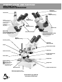
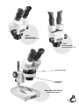
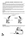
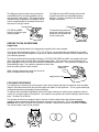
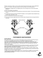
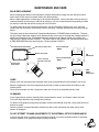
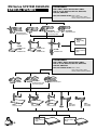
CONTENTS NOMENCLATURE AND FUNCTION UNPACKING, ASSEMBLY, PREPARATION FOR USE 2-3 4 Unpacking Assembly OPERATING PROCEDURES How to Operate Illuminators Focusing Capability Precise Focus On Specimen 5-7 5 5-6 6 Focusing Procedure 6-7 PHOTOGRAPHY AND TELEVISION 7-8 Photography 7 Camera Operation 8 Television 8 MAINTENANCE AND CARE 9 Bulb Replacement Care Cleaning SYSTEM DIAGRAM 10 - 13 EMZ Series INSTRUCTION MANUAL 1 NOMENCLATURE AND FUNCTION MEIJI EMZ Series ZOOM STEREO MICROSCOPE Eyepieces with Eyeshield Photo Tube Diopter Adjustment Ring Eyepieces with Eyeshield Lever for switching the image from one of the binocular eyepieces vertically up to the film plane Diopter Adjustment Ring Photo Tube EMZ-5TR Trinocular Zoom Stereo Body Eyetube Inclination : 45 。 Zoom Control Knob EMZ-8TR Trinocular Zoom Stereo Body Eyetube Inclination : 45 。 Diopter Adjustment Ring Focusing Knob Eyepieces with Eyeshield Clamp Zoom Control Knob Objectives Collar Set Screw Incident Illuminator Lamp Cover Pillar Collar Stage Clips Selector Switch ( Ⅰ ) :Incident Light ( T ) :Iransmitted Light (ⅠT) T) :Incident and Stage Plate Transmitted Lights simultaneously Dimmer Switch Stage Plate Set Screw Base with Transformer and Transmitted Illuminator built in 2 Model EMZ-5 with SWF10X mounted on PBH Stand EMZ-9 Zoom Stereo Body 。 Eyetube Inclination : 60 Z-7100 Zoom Stereo Body 。 Eyetube Inclination : 90 Zoom Control Ring Clamp Screw Set Screw Model EMZ-2 with SWF10X mounted on P Stand 3 UNPACKING, ASSEMBLY, PREPARATION FOR USE UNPACKING All MEIJI TECHNO microscopes are usually supplied in an expanded polystyrene, 2-part case and this should be used for storage, possible transport in the future, etc. If your order includes a wooden storage cabinet, release the fixing screws holding the limb and base into the cabinet and withdraw. Unpack the microscope and its parts carefully. Do not discard any boxes or packing materials until the contents of the shipping container have been checked against the packing list sent and your order. If an EMZ Zoom stereo microscope has been shipped, base, limb and zoom stereo body will be shipped together as a unit. Remove from the styrofoam back, holding the base in one hand and supporting the zoom stereo body with the other. Place the microscope and parts on a sturdy table or desk which gives firm and stable support. This should be located where the atmosphere is as clean as possible, avoiding places where there is excessive dust, moisture, heat or fumes. ASSEMBLY When in place, insert eyepieces in the eyetubes of the binocular body. Zoom stereo body are already in place on the limb, as shipped. Cover with the plastic dust cover supplied until ready for adjustment and use. If you ordered zoom stereo body and stand separately, loosen the set screw and insert the zoom body into the holder then tighten the set screw after setting at the desired position. Insert the eyepieces into eyetube Zoom body can rotate 360 degree on the holder Set screw Holder IMPORTANT! Before plugging the illuminator into any electric outlet, make sure that transfomers and illumination bases supplied to you are suitable to the current available. (When shipped, these will be labelled as to mains voltage and cycles specification.) Main voltage label 4 MAINS AC100V-120V OPERATION PROCEDURES HOW TO OPERATE ILLUMINATORS How to use selector switch Focusing stands, PB and ABZ, are using 6V 1.2A (7W) tungsten filament bulb with suitable transformer built-in base and selector switch on the base. Turn the selector switch knob to indicate [ I ] for oblique illumination, to indicate [T] for transmitted illumination and [IT] for simultaneous illumination by oblique and transmitted lights. The selector switch has OFF position at the both right and left ends. Selector Switch OFF I T IT OFF How to use selector switch and dimmer switch Focusing stands, PBH, ABZH and ABE, are using 6V 10W Halogen lamps with suitable transformers builtin base and a selector switch and a dimmer switch on the base. Select an illuminator to use, either incident or transmitted, by the selector switch in the way described above. Then, turn the dimmer switch knob slowly to clockwise to turn the dimmer switch ON and to increase brightness. Turn the knob to counterclockwise to decrease the brightness and to turn OFF. Selector Switch OFF I T IT OFF Dimmer Switch FOCUSING CAPABILITY The Pole-type focusing stands have a double focusing capability, i.e. Rough Focus (by sliding the whole focus assembly and zoom body up and down on the pillar, fixing the clamp screw when in approximate focus on your specimen), Precise Focus (by using the rack and pinion focusing knob). The focusing stands, P, PL, PX, PC, PB, PBH and BX are the Poletype. Focusing assembly Focusing Knob Clamp Screw Pillar collar and clamp Screw Before moving the whole focus assembly up and down for rough focus, loosen pillar collar once and make sure to reset after the rough focusing is done. 5 The Rigid arm type focusing stands (except the model ABE) have a focusing capability only by rack and pinion adjustment. This means that the available range of specimen sizes/depths which can be accommodated is somewhat less than in the case of Pole-type stands. The Rigid arm type ABE focusing stand is with integral focus block and extendable working distance. Provides transmitted and incident halogen illumination. Clamp Screw Focusing Screw AZ, ABZ and ABZH stands are rigid arm type focusing stands. To extend working distance, loosen the clamp screw and extend the arm upward and set the screw back. ABE Extendable PRECISE FOCUS ON SPECIMEN Stage Plates You should now decide which of the stage plates supplied will be most suitable. The focusing stands with plain bases, P, PL, PX, PC and A, are supplied with reversible black and white stage plates. Your selection depends on which side, black or white, gives the best contrast conditions with your selected specimen. The focusing stands with transmitted illuminators, PB, PBH, ABZ, ABZH and ABE, are supplied with clear glass stage plates and reversible black and white stage plates. If the specimen is semi-transparent, the glass stage plate shoud be used with transmitted illumination switched on. If the specimen is opaque, use the black/white stage. Your selection depends on which side, Black and White black and white, gives the best contrast. Stage Plate When replacing stage plate loosen the set screw which is visible infront of the stage. Stage plate set screw FOCUSING PROCEDURE The whole point of stereoscopic microscopes is that, when properly adjusted, the observer sees the object image in three dimensions and can perceive height and depths on the specimen. This is a great advantage in material examination and quality control techniques. To achieve these desirable height/depth effects the images coming from the binocular eyepieces must be "fused" into a single image by the observer - this requires some practice and careful setting of the binocular body. Procedure is as follows:The operator should move eyepiece tubes in and out to find the place where the distance between eyepiece centers matches the distance between the pupils of his own eyes. This is the interpupillary distance and will vary somewhat from operator to operator. When these distances are equal (or match), one central image is seen by the operator. 54-74mm "Fused" 6 Finally it is necessary to adjust, so focus remains sharp through the whole range of zoom magnification and so that the image is seen equally sharply focused in both right and left-hand eyepieces. (1) Set microscope magnification to the highest power 4.5X by turning the zoom control knob counterclockwise. (2) Then focus sharply on the specimen. (3) Set to the lowest magnification by turning the zoom control knob clockwise. Do not touch the focusing controls. (4) Looking with the right eye through the right-hand eyepiece, turn the eyepiece’s dioper adjustment ring until the image is precisely in focus. (5) Do the same with the left eye and left-hand eyepiece. (6) The fused microscope image should now be uniformly sharp throughout the zoom range and without refocusing. Zooming control knob 4.5X 0.7X Eyepiece Diopter PHOTOGRAPHY AND TELEVISION PHOTOGRAPHY Photographic documentation of microscope visual images is most conveniently achieved by using the trinocular (photo-binocular) bodies offered for use with MEIJI TECHNO microscpoes. In the case of the EMZ-TR Zoom Stereo series a trinocular is supplied with lever-switching of the image from one of the binocular eyepieces vertically up to the film plane of a 35mm SLR camera with adaptor mounted on the vertical photo tube. Visual observation can be simultaneously carried out, using the other eyepiece. In this system the MA150/50 and MA150/60 Camera Attachment should be used with the SLR camera model of your choice. Please note that one of the large range of T2 Adaptor Rings suiting to your camara should have been ordered and supplied. These adaptor rings are intended to compensate for the small differences in effective distance of the film plane in your camara - so as to ensure that photographs are optimally sharp, and achieved without wastage of film in trial shots and experimentation. In addition special low-power camara eyepieces (2.5X, 3.3X and 5X) are available and recommended - these will give you maximum field coverage on your speciment while using the convenient and economical 35mm film format 7 35mm SLR Camera Body CAMERA OPERATION (1) Fix your 35mm SLR camera on the MA150/50 or MA150/60 Camera Attachment, then mounting this assembly on the straight tube of the trinocular body. (2) Pull out the lever on your trinocular body so as to send the image both to the camara and the visual eyepiece. (3) Rotate the adjustment ring on the straight tube so as to set the red indicator line on the upper tube portion at the top edge of the lower tube. Then fix in place with the clamp screw. You now should be set correctly for optimum conditions of simultaneous visual observation and photography. Lever Switching T2 Adapter T2-1 Canon T2-2 Minolta T2-3 Pentax K Pentax S T2-4 T2-5 Nikon T2-6 Olympus T2-7 Contax, Yashica Konica T2-8 T2-9 Canon EOS T2-10 Minolta α/ Maxim 2000 MA150 / 60 Camera Attachment w/finder eyepieces MA150 / 50 Camera Attachment Photo Eyepieces MA512 2.5 X MA500 3.3 X MA508 5.0 X EMZ Series TRINOCULAR VIEWING HEADS EMZ-5TR, EMZ-5TRD, EMZ-2TR, EMZ-8TR, EMZ-8TRD TELEVISION For television the MA 151/5N (EMZ-TR) "C" Mount Adaptor should be used, threaded into your TV camera, then placed and adjusted on the upper portion of your trinocular body. Adjustment can then proceed a per paragraph (3) above. You should understand that the comparatively large magnification factors inherent in most TV camera/monitor systems will restrict your fields of view (while blowing up total magnification). A correct optical set-up and adjustment is, of course, crucial to obtaining a good TV monitor image, but keep in mind that the monitor controls for brightness and contrast adjustment are also important and should also be experimented with in order to obtain the best monitor image. CK3900N or CK3900P CCD Camera MK300N or MK300P B/W CCD Camera CK3900N or CK3900P CCD Camera "C"Mounts with Lens MA151/35/03 0.3 X MA151/35/04 0.4 X MA151/35/15 1.0 X MA151/35/20 0.7 X MA151/35/25 2.5 X Lever Switching 8 EM Series TRINOCULAR VIEWING HEADS ZOOM HEADS (TRINOCULAR) EMZ-5TR, EMZ-2TR, EMZ-8TR, EMZ-12TR MK300N or MK300P B/W CCD Camera "C"Mounts* MA151/5N *Existing photo tube should be removed before mounting MA151/5N "C" mount MAINTENANCE AND CARE BULB REPLACEMENT When changing light bulbs in the illuminators, always disconnect the plug from the electrical source. Never work on the electrical system without first disconnecting. When a bulb replacement is necessary in the Incident Illuminator, remove the lamp cover by turning it counterclockwise and remove the old bulb by twisting it 1/3 turn counterclockwise by pushing it toward the socket so that the bulb will be sprung out from its socket. To replace the bulb of the Transmitted Illuminator, lay the instrument carefully over on its side and remove the four set screws in the bottom cover of the base. Replace the old bulb in the same way as above. The bulbs used for the Incident and Transmitted Illuminators of PB/ABZ stand are different. The bulb for the Incident Illuminator employs a flat filament facing to the head of the bulb and Catalog Number is MA560 and the bulb for the Transmitted Illuminator employs a flat filament facing to the side of the lamp and the Catalog Number is MA561. The bulbs used for the Incident and Transmitted Illuminators of PBH/ABZH/ABEstand are same halogen. Catalog number is MA570. bulb replacement Set screw in rubber foot ●For Incident light MA560 Bottom cover plate 26mm ●For Turn to unscrew the lamp cover here Transmitted light MA561 ●Incident bulb replacement ●Transmitted PB ABZ Stands 26mm ●For Both light MA570 PBH ABZH ABE Stands 25mm CARE Always cover the instrument with the plastic dust cover provided when the microscope is not in use. Keep the eyepieces in the microscope body at all times in order to prevent dust from falling on the internal optics. Store the microscope in a safe, clean place when not in use for an extended period of time. CLEANING Clean exposed lens surfaces carefully with a pressurized air source, soft brush or clean soft cloth. Too much finger pressure may damage lens coatings. To remove oil fingerprints and grease smudges, moisten the cleaning cloth with a very small amount of alcohol or xylene. Painted or plastic surfaces should be cleaned only with a cloth moistened with water and a small amount of detergent. DO NOT ATTEMPT TO MAKE ADJUSTMENTS TO THE INTERNAL OPTICS OR MECHANICS!! If the microscope does not seem to be functioning properly or you have questions about its operation, call your supplier (or an authorized repair service) for advice. 9 EM Series SYSTEM DIAGRAM ZOOM MODELS MA550 Polarizing filter (Analyzer) Photo/Video attachments are show in Page 13 MA531 Protective glass Auxiliary lenses MA530 0.3X MA525 0.44X EMZ-1 MA517 0.5X MA526 0.75X EMZ-2 MA507 1.5X MA511 2.0X EMZ-5 EMZ-5D EMZ-2TR STAND PBH Pole type PB Pole type w/halogen 6V 10W w/tungsten 6V 7W trans/incident trans/incident lights PC Plain Pole PX Pole type PL Pole type w/coaxial focusing w/illuminator port w/illuminator port 10" Piller P Plain Pole type AZ Plain Rigid-arm MA568 B/W Plastic stage plate MA551 Extension pole MA551 Extension pole MA551 Extension pole MA551 Extension pole MA551 Extension pole MA551 Extension pole MA567 Acrylic frosted stage plate MA567 Acrylic frosted stage plate MA568 B/W Plastic stage plate MA568 B/W Plastic stage plate MA568 B/W Plastic stage plate MA568 B/W Plastic stage plate MA569 Clear glass stage plate MA569 Clear glass stage plate MA667 Polarizing Plate (Polarizer) 10 MA564/05 Graduated mechanical stage with clear glass plate MA565/05 Ungraduated mechanical stage with clear glass plate MA565 Ungraduated mechanical stage MA564 Graduated mechanical stage EYEPIECES, Paired MA501 SWF5X MA502 SWF10X MA520 SWF12.5X MA503 SWF15X MA535 HSWF15X Auxiliary lenses EMZ-8TR EMZ-8TRD ABZ Rigid-arm w/tungsten 6V 7W trans/incident lights EMZ-6 MA521 SWF30X MA519* SWF10X-F *(Piece) Auxiliary lenses MA791 MA792 MA794 MA795 0.28X 0.35X 0.5X 1.5X EMZ-5TR EMZ-5TRD MA504 SWF20X Auxiliary lenses MA545 MA558 MA546 MA547 MA548 MA549 0.3X 0.44X 0.5X 0.75X 1.5X 2.0X EMZ-9 EMZ-10 Z-7100 ABZH Rigid-arm w/halogen 6V 10W trans/incident lights ABE Extendable w/halogen 6V 10W trans/incident lights BX Stand w/mirror for B/D (light not included) MA567 Acrylic frosted stage plate MA567 Acrylic frosted stage plate MA567 Acrylic frosted stage plate MA551 Extension pole MA569 Clear glass stage plate MA569 Clear glass stage plate MA569 Clear glass stage plate MA567 Acrylic frosted stage plate EMZ-12 EMZ-12D MA600 EYESHIELD MA652 MA796 0.7X 0.57X EMZ-12TR EMZ-12TRD KBL Pole type w/illuminater port on flat base EMZ-12 FL150 and FL150/12 MA551 Extension pole MA569 Clear glass stage plate KBE Rigid-extendable arm on flat base MA564/05 Graduated mechanical stage with clear glass plate MA565/05 Ungraduated mechanical stage with clear glass plate MA667 Polarizing Plate (Polarizer) 11 EM Series SYSTEM DIAGRAM SPECIAL STANDS ZOOM HEADS EMZ-1, EMZ-2, EMZ-5, EMZ-5D, EMZ-6, EMZ-9, EMZ-10, Z-7100, EMZ-2TR, EMZ-5TR, EMZ-5TRD, EMZ-8TR, EMZ-8TRD EMF, EMT VIEWING HEADS: EMF-1, EMF-2, EMT-1, EMT-2, EMT-3, EMT-4, EMTR-1, EMTR-2, EMTR-3, EMTR-4, FS Holder w/illuminator port for bonding machine F Holder FC Holder w/coaxial coares and fine focusing block FX Holder w/illuminator port MA574 Large Sliding Stage S-4300 w/400mm Pole S-4400 w/610mm Pole S-4100 w/400mm Pole S-4200 w/610mm Pole MA575 Medium Sliding Stage S-4500 w/400mm Pole ZOOM HEADS EMZ-1, EMZ-2, EMZ-5, EMZ-5D, EMZ-6, EMZ-9, EMZ-10, Z-7100, EMZ-2TR, EMZ-5TR, EMZ-5TRD, EMZ-8TR, EMZ-8TRD EMF, EMT VIEWING HEADS: EMF-1, EMF-2, EMT-1, EMT-2, EMT-3, EMT-4, EMTR-1, EMTR-2, EMTR-3, EMTR-4, F Holder SBU Universal Stand 12 FC Holder w/coaxial coares and fine focusing block UL Universal Stand MA574 Large Sliding Stage FX Holder w/illuminator port MU Universal Stand FA-1 Articulated Arm Stand MA575 Medium Sliding Stage FA-2 Articulated Arm Stand EM Series SYSTEM DIAGRAM VIDEO MICROSCOPY CK3900N or CK3900P CCD Camera MK300N or MK300P B/W CCD Camera "C"Mount "C"Mount with lens MA151/10 MA151/8TR 0.6X CK3900N or CK3900P CCD Camera MA151/35/03 MA151/35/04 "C"Mounts with Lens MA151/35/15 MA151/35/20 MA151/35/25 MK300N or MK300P B/W CCD Camera 0.3 X 0.4 X 1.0 X 0.7 X 2.5 X "C"Mounts* MA151/5N *Existing photo tube should be removed before mounting MA151/5N "C" mount EMZ Series TRINOCULAR VIEWING HEADS EMZ-5TR, EMZ-5TRD, EMZ-2TR, EMZ-8TR, EMZ-8TRD EMZ-8TR EMZ-8TRD EMT VIEWING HEADS (TRINOCULAR) 35mm SLR Camera Body T2 Adapter MA150 / 50 Camera Attachment T2-1 Canon T2-2 Minolta T2-3 Pentax K T2-4 Pentax S T2-5 Nikon T2-6 Olympus T2-7 Contax, Yashica T2-8 Konica T2-9 Canon EOS T2-10 Minolta α/ Maxim 2000 MA150 / 60 Camera Attachment w/finder eyepieces NIKON, OLYMPUS, FUJI, DIGITAL Camera DIGITAL Camera adapter Photo Eyepieces MA512 2.5 X MA500 3.3 X MA508 5.0 X EMZ Series TRINOCULAR VIEWING HEADS EMZ-5TR, EMZ-5TRD, EMZ-2TR, EMZ-8TR, EMZ-8TRD EMT VIEWING HEADS (TRINOCULAR) EMTR-1, EMTR-2, EMTR-3, EMTR-4 DIGITALCAMERAS EM Series SYSTEM DIAGRAM PHOTO MICROSCOPY MICROSCOPES EMTR-1, EMTR-2, EMTR-3, EMTR-4 Fits a 23.2mm I.D./25.2mm O.D. Eye tube or Fits a 30.5mm I.D./34.0mm O.D. Eye tube of: EMZ-TR ZOOM TRINOCULAR HEADS: EMZ-2TR, EMZ-5TR, EMZ-5TRD, EMZ-8TR. EMZ-8TRD, EMZ-12TR, EMZ-12TRD EMZ ZOOM HEADS: EMZ-1, EMZ-2, EMZ-5, EMZ-6, EMZ-9, EMZ-10, EMZ-12, Z-7000 EMTR HEADS: EMTR-1, EMTR-2, EMTR-3, EMTR-4 EMT,EMF HEADS: EMF-1, EMF-2, EMT-1, EMT-2, EMT-3, EMT-4, NIKON Coolpix 950 990 995 MA151/30/50 MA151/45/50 NIKON Coolpix 5000 MA151/30/70 MA151/45/70 Olympus Camedia C-3040 Zoom MA151/30/60 C-4040 Zoom C-3100 Fuji Finepix S602 MA151/30/80 4900Z 6900Z MA151/45/60 MA151/45/80 EMZ ZOOM Series BINOCULAR HEADS EMZ-1, EMZ-2, EMZ-5 13 322-1,Chikumazawa Miyoshi-machi, Iruma-gun Saitama 354-0043, Japan E-mail : [email protected] Phone : (0)49-259-0111 Fax : (0)49-259-0113 2186 Bering Drive San Jose, CA., 95131, USA E-mail : [email protected] Phone : 408-428-9654 Fax : 408-428-0472 Toll free : 800-832-0060 http :/ /w w w .m e ijit e c hno.c om 03.09.2,000 V1 Printed in Japan


![訟 NA TW]N](http://vs1.manualzilla.com/store/data/006574871_2-701642caad671571359886c7e3222bf0-150x150.png)