1
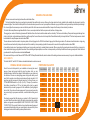
)))
XENITH
SERIES
AMPLIFIER INSTALLATION GUIDE
Thank you for purchasing this Cadence Xenith Series amplifier.
Cadence has been producing quality car audio electronics for more than 16 years and while so many car audio brands have
come and gone, Cadence has withstood the test of time which is a testament to our success. But we know that our success
couldn’t have been achieved with out you our customer whose faith in our brand has taken us so far.
As with all Cadence amplifiers, you will be amazed at the quality and power that these new Xenith amplifiers offer. You will "BoomHarder!" with Cadence Xenith amplifiers.
No expense has been spared in the designing and testing of these amplifier. Our goal was to achieve the most rugged, reliable,
powerful and best performing amplifiers. In fact we are so sure of the quality we backup every Xenith Series amplifier with our
exclusive two-year warranty which exemplifies our commitment to excellence in car audio musical reproduction. (See enclosed
warranty card for details.)
Please read this installation guide carefully for proper use of your Cadence power amplifier. Should you need technical
assistance during or after your installation please call our technical-line between 9:30 am and 5:00 PM EST at 732/370-5400.
Read this entire guide fully before attempting your installation. You can also get technical help via e-mail at
[email protected]. Kindly allow us 24-48 hours to respond to e-mail technical assistance.
WARNING: BE AWARE! Use of this amplifier at extreme high volumes for extended periods of time may cause hearing loss and
or hearing damage. During periods of prolonged high volume levels it is recommended that you use ear safety devices. Playing
Cadence amplifiers at high volume levels while driving will impair your ability to hear necessary traffic sounds. While driving
always keep your sound volume at reasonable levels. The folks at Cadence want you listening for many years to come.
)))
When installing the amplifier, secure it tightly. An unmounted amplifier in your car can cause serious injury to passengers and
damage to your vehicle if set in motion by an abrupt driving maneuver or short stop.
2
XENITH
)))
XENITH
POWER AND PROTECTION CIRCUITRY:
Xenith Series amplifiers feature our unique IC controlled protection circuitry. This sophisticated circuit constantly monitors the heat sink internal temperature and various voltages,
adjusting the amp automatically and protecting it from dangerous conditions. The 2 LED’s located on top side of the amplifier provide indication of the amplifier status, the Power LED will
light when the amplifier is receiving proper power, ground and remote voltages and the IC monitoring sequence indicates the amp is functional. In case the amplifier encounters a
diagnostic condition as listed below, the second LED will light indicating a Diagnostic condition. When a diagnostic condition is sensed the amplifier will then turn in to a self preservation
mode and if the cause of the diagnostic condition is not corrected will eventually shut down. There are certain critical diagnostic conditions which will turn the amplifier off immediately.
1. Speaker short circuit. / 2. Input Overload. / 3. Thermal overload. / 4. Reverse Polarity.
To reset the amplifier, you must first diagnose what caused the problem, correct the fault and restart the system. See the Trouble Shooting page for further details.
MUTE CIRCUIT:
The Xenith Series amplifiers feature an anti-thump, mute and delay circuit. This eliminates irritating speaker damaging turn-on and turn-off transients normally experienced with
less expensive amplifiers.
BASS EQUALIZATION CIRCUITRY:
All Xenith mono block amplifiers feature a narrow "Q" shelving equalization circuit. The equalization system is preset at 45Hz. The boost control allows you to +6dB or +12dB of Bass EQ
effect. Utilize the Bass EQ to tailor your bass response to your systems needs. Please keep in mind that by adding Bass EQ you are adding stress on your speakers. Make sure your
speakers can handle the extra power output! It would be foolish to add 12dB of gain to low excursion 8" and 10" Sub woofers or mid ranges and tweeters. It’s a sure way to blow your
speakers. The Bass EQ was designed for High Power sub woofers. The audio output section of the Xenith Series amplifiers feature Japanese studio grade, high current Bi-Polar audio
transistors. Unlike other manufacturers who use a host of different type transistors, not originally designed for audio output, i.e.: power supply transistors, motor control transistors to
produce the audio signal, (you can only begin to imagine what they sound like.) Cadence uses only true audio transistors in the audio section of their amplifiers. These transistors were
designed and engineered to produce music. That’s why Cadence amplifiers clearly sound better. They are cleaner with lower distortion, higher current capable and more reliable. We
challenge you to test listen a Cadence amplifier and hear the difference yourself.
WIRELESS PCB DESIGN
Cadence Xenith amps, feature black pcb designs with a clear solder mask. All circuitry has been designed on to the PCB and all high current traces are provided through heavy duty bus
bars or secondary pc boards. You wont find any wires looping around a Xenith amp typical of cheap amplifier designs. By engineering all circuitry directly to the PCB we are able to
produce a more powerful amp, that is more efficient and has lower distortion rates.
BATTERY VOLTAGE:
Cadence Xenith Series amplifiers are rated and regulated to 13.8 volts and below. Increasing voltage to 14.4 volts will increase the power output of the amplifier in the same proportion.
Maximum input voltage is 14.4 volts while the minimum voltage is 12 volts.
DO NOT EXCEED 14.4 INPUT VOLTAGE.
Though capable of high power reproduction, Cadence Xenith Series amplifiers are not competition style amplifiers! They were designed for audiophile sound reproduction.
3
PROTECTION CIRCUITRY:
Cadence amplifiers incorporate many outstanding protection circuits to help protect the amplifier from being damaged during operating conditions.
Thermal Protection: When the amplifier reaches an unsafe operating temperature of 80 degrees Celsius the amplifier will turn off. Once the amplifier cools down, simply reset the
amplifier by its Remote connection, (turn the amplifier off and then on again once you have given the amplifier a chance to cool down) and the amp will once again begin to play.
If you live in a hot climate we suggest installing additional cooling fans in your trunk to exhaust the hot air which can build up in the trunk this will help keep the ambient temperature in the
trunk as low as possible so that your amps work flawlessly and without any musical interruption.
Speaker Short Circuit Protection: Should your speakers short circuit due to voice coil burn out, or should the amplifier sense an impedance too low to handle, the Protection LED will light,
indicating a diagnostic condition. Turn off your system, disconnect one speaker at a time and try to determine which speaker might be faulty. Correct the condition and restart the amplifier.
You must reset the amplifier by turning it OFF and then ON again by the Remote power connection after correcting a diagnostic condition. (Turn your radio off and then on again.)
Clipping or total shutdown may also be a result of a bad ground connection or loose ground. If you find that your speakers and speaker wires are not shorted, please check your ground
connection.
Input Overload Protection: This circuit will either shutdown the amplifier completely or make the amplifier spurt on and off indicating that it is in a diagnostic condition. Turn the system off
and reduce the gain on the amplifier or volume from your head unit, this should result in a corrected condition.
DC Offset Protection: Should any DC voltage try to enter the amplifier via the speaker terminals it will cause the amplifier to shut down and not operate until this condition is remedied. This
circuit will also protect damaging high DC voltages from reaching your speakers should your amplifier ever malfunction.
INSTALLATION BASICS:
Before you begin with your installation, disconnect the NEGATIVE (-) terminal from your car's battery. This safety precaution will avoid possible short circuits while wiring your amplifier.
Cadence amplifiers operate on 12-volt negative ground systems only.
It is recommend that you layout your sound system design on paper first. This will help you during the installation so that you will have a wiring flow chart and not miss-wire any of your
components.
Mount the amplifier in the trunk or hatch area of your vehicle. Never install an amplifier in the engine compartment or on the firewall. Please be sure to leave breathing room around the
amplifier heat sink so that it can dissipate the heat it produces efficiently. The amplifier can be installed either horizontally or vertically. When mounting the amplifier on the trunk floor, be
sure to watch for your gas tank, gas lines and electrical lines. Do not drill or mount any screws where they might penetrate the gas tank of your car.
POWER/GROUND WIRING:
The Xenith Series amplifiers are supplied with built-in fuses, never replace the fuse that the amp came with, with one of a larger value.
)))
We suggest you construct a Red wiring harness with 2 additional fuse. One fuse should be located near the car battery. This fuse near the battery offers protection against damage from
short circuits to the car chassis between the battery and the amplifier. A second fuse closer to the amplifier offers additional safety to the amplifier itself. This fused red power wire should
be attached to the amplifier power terminal marked 12V+.
4
XENITH
)))
XENITH
The wire harness should be made of red primary cable of at least 8 gauge for the Xa125.2 and at least 4 gauge for all other larger models. The harness should terminate in a
large ring terminal for connection directly to the positive terminal of the car battery. Use a spade plug to attach the wire, which connects to the amplifier location marked 12V+.
A second black color wire of equal gauge should be used as a ground connection to a welded chassis member. When connecting the ground wire make sure that there is no paint or
other insulator blocking a good ground connection. When installing multiple amplifiers, mount them in close proximity so that they can all share the same ground point. Attach the black
ground wire to the amplifier screw terminal marked Ground.
We recommend that you use the Cadence AMP1000 or AMP1500 amplifier installation kits, which contains all the cabling and accessories necessary for a good, reliable installation.
Over the years we have received amplifiers back to our service department with melted power/ground terminals. The cause of this is a bad ground connection. When there is a lack of
good ground, heat builds up at the weakest point which happens to be the contact screw of the amplifier terminal. Over time the heat generated will begin to melt the terminal. It is a good
practice to feel the power and ground wires with your hands, near their amplifier connection after having played the amp for a while. If the wires feel hot to the touch you probably have a
bad or loose connection. If you are sure of your connections and the wires still feel hot to the touch, you should upgrade the gauge of wire to next heaviest gauge.
REMOTE TURN ON CONECTION:
The remote turn on connection is located on the barrier strip next to the power and ground connections. This connection is responsible for turning the amplifier on and off with the rest of
the system. A smaller gauge wire can be used to make this connection to your radio's power antenna lead. Should your system not have any turn on leads, you can wire the remote
terminal to an accessory lead, which turns on, with your cars ignition.
SETTING THE CONTROLS
AUDIO PREAMP INPUT
The Xenith Series amplifiers feature RCA pre amp inputs. Run RCA cables from your sound source to the inputs of the amplifier. We suggest the use of high quality shielded RCA patch
cords to help reduce and eliminate unwanted electrical noise to your system.
Be sure to run the RCA cables on the opposite side of the vehicle that you used to carry the power and ground leads of the amplifier.
USING THE BUILT-IN LOW PASS ELECTRONIC CROSSOVER
All the Xenith Series amplifiers feature 12dB per octave fully adjustable low-pass and high pass electronic crossovers.
For Low Pass sub woofer systems, set the CROSSOVER MODE switch to LOW PASS. Now the knob marked FREQUENCY will control the low pass frequencies from 40Hz to 160H on
stereo amplifiers and 40Hz to 250Hz on mono block amplifiers. A frequent error made is setting the low pass frequency too low, especially when using vented sub woofer enclosures.
We recommend that for most installations you do not set the frequency knob lower than 80 - 100Hz (the 12 o’clock position).
When using the amplifiers for component speakers or co-axials, you will want to set the CROSSOVER MODE switch to HIGH PASS. The FREQUENCY control knob adjusts the high
pass frequencies between 40Hz and 6000Hz. Do not attach tweeters directly to the amplifier, (even in the high pass mode) without a secondary passive crossover to protect
them.Typically 600Hz high pass is not ahigh enough cut-off frequency for tweeters.
SUBSONIC FILTERING
For sub woofer installations with a passive LP crossove installed on the woofer, you can set the amplifier’s CROSSOVER MODE selector to HIGH PASS while setting the FREQUENCY
KNOB to 40Hz, this will act as SUBSONIC FILTER for all signals below 40Hz. This is especially useful for vented enclosures where the port tuning frequency falls below the sub woofer
tuning frequency to protect against sub woofer unloading.
5
ADJUSTING THE SYSTEM
Once the system is operational, the first thing to do, is set all crossover points to approximate settings. In the case of the basic sub woofer system Low Pass filter crossover at 100 Hz or
so. Set the Bass Boost equalizer controls to 0 dB ( Flat Switch Position.)
Now you should set the amplifiers Input Sensitivity adjustment. The knob accessible on the side of the amplifier marked INPUT GAIN adjusts the input sensitivity from 200mV to 8Volts.
To adjust the input sensitivity, turn the control using a small flat head screwdriver fully counter clock wise to the minimum position. Do not apply any pressure while turning as this might
break the control unit. Adjust your radio volume level to maximum volume. Now turn the level control on the amplifier clockwise towards the Maximum marking until audible distortion
occurs. When you begin to hear any distortion in the sound, back down one notch and your amp is set. It is helpful to have a second person to help you set the gain.
When setting up a multi-amp system, set each amplifier’s gain separately. Start off with the bass amplifier, then adjust the highs amplifier’s level control to match.
Once you are satisfied with the level control settings, use any equalizer controls to adjust the system tonal level for personal preference. Keep in mind that after equalizing, you may
have to go back and reset the amplifiers level controls.
The level control of any car amplifier should not be mistaken for a volume control. It is a sophisticated device designed to match the output level of your source unit to the
input level of the amplifier. Do not adjust the amplifier gain to maximum unless your input level requires it.
If your unit has been professionally installed please do not change the gain settings set by the installer, he is the professional!
Your system can also be extremely sensitive to noise when the LEVEL is set to maximum and does not match your input signal. The gain adjustments need to be made only once when
first setting up the system.
USING THE ELECTRONIC CROSSOVER - 4 CHANNEL MODEL
The four channel models feature separate crossovers for channels 1-2 and 3-4. All the Xenith Series amplifiers feature 12dB per octave fully adjustable low-pass and high pass
electronic crossovers.
FOUR CHANNEL AMPLIFIER CONFIGURATIONS.
1. All four channels High Pass for internal component speakers in doors and rear decks.
2. Channels 1 and 2 High Pass for front component speakers, while channels 3 and 4 are wired to sub woofers.
3. Bridge channels 1 and 2 for single high power sub woofer channel. Bridge channels 3 and 4 for second high power sub woofer channel.
For Low Pass systems, set the CROSSOVER MODE switch to LOW PASS. Now the knob marked FREQUENCY will control the low pass frequencies from 40Hz to 160Hz. A frequent
mistake made is setting the low pass frequency too low, especially when using vented sub woofer enclosures. We recommend that for most installations you do not set the frequency
knob lower than 100Hz (the 12 o’clock position).
)))
When using the amplifiers for component speakers or coaxial, you will want to set the CROSSOVER MODE switch to HI PASS. The FREQUENCY control knob adjusts the high pass
frequencies between 40Hz and 600Hz. Do not attach tweeters directly to the amplifier even in the high pass mode without a secondary passive crossover to protect them. 600Hz high
6
XENITH
)))
XENITH
MOUNTING THE AMPLIFIER:
Choose a convenient mounting location with unobstructed airflow.
The Xenith amplifiers feature four mounting holes located at the amplifiers four corners. Remove the 4 caps which are factory installed in the amplifier side trim panels. Insert the
screws and tighten. You should first drill a pilot hole in the location where you wish to mount your amplifier so that when you go install the mounting screws they install easily and straight.
Do not over tighten the screws as you can crack the trim panel. After all 4 screws are mounted reinstall the 4 caps so that the amp is trimmed nicely from above.
The Xenith Series amplifiers are supplied with built-in fuses, never replace the fuse that the amp came with, with one of a larger value.
We suggest you construct a Red wiring harness with 2 additional fuse. One fuse should be located near the car battery. This fuse near the battery offers protection against damage from
short circuits to the car chassis between the battery and the amplifier. A second fuse closer to the amplifier offers additional safety to the amplifier itself. This fused red power wire should
be attached to the amplifier power terminal marked 12V+.
The wire harness should be made of red primary cable of at least 8 gauge for the FX2060 and at least 4 gauge for all other larger models. The harness should terminate in a large ring
terminal for connection directly to the positive terminal of the car battery. Use a spade plug to attach the wire, which connects to the amplifier location marked 12V+.
A second black color wire of equal gauge should be used as a ground connection to a welded chassis member. When connecting the ground wire make sure that there is no paint or
other insulator blocking a good ground connection. When installing multiple amplifiers, mount them in close proximity so that they can all share the same ground point. Attach the black
ground wire to the amplifier screw terminal marked Ground.
We recommend that you use the Cadence AMP1000 or AMP1500 amplifier installation kits, which contains all the cabling and accessories necessary for a good, reliable installation.
BASS REMOTE.
The Xenith Xa400.1 and XA175.2 feature a standard dashboard mount bass remote.
POWER & GROUND CABLE GAUGE:
One of the most critical points of your installation is choosing the correct
gauge of power and ground cable By using the above chart, you can
calculate based on the total fuse ratings of the amplifiers in your system and
the distance of the wire run, what gauge power and ground cable you will
need. So for example in a multi amp system where the sub amp has 2 x 30
amp fuses and the component 4 channel amp has 2 x 25 amp fuses, your
TOTAL AMPERAGE would be (2 x30) + (2 x 25) = 110 amps. If your wire run
from battery to amplifiers is 7-10 feet, by looking at the chart you would
determine that you need 4 gauge wire for ths installation. (See highlighted
box in chart.) You must use the same gauge wire for your ground connection
as you are using for your power connection, no matter how short the ground
run is.
We strongly suggest that after playing your system for 30-60 minutes that
you touch the wire insulation close to the battery terminal and the amplifier
positive and ground terminals.(MAKE SURE YOUR CAR IS OFF WHEN
YOU DO THIS!) If they are hot to the touch you should increase the gauge of
your wire and also double check your connections to make sure that you are
making good contact with the battery and amplifier terminals.
POWER CABLE CALCULATOR
TOTAL AMPERAGE
0-4 FT
4-7 FT
7-10 FT
10 -13 FT
13-16 FT
16-19 FT
19-22 FT
22-28 FT
0 – 20
14
12
12
10
10
8
8
8
20 – 35
12
10
8
8
6
6
6
4
35 – 50
10
8
8
6
4
4
4
4
50 – 65
8
8
6
4
4
4
4
2
65 – 85
6
6
4
4
2
2
2
0
85 – 105
6
6
4
2
2
2
2
0
105 – 125
4
4
4
2
0
0
0
0
125 – 150
2
2
2
0
0
0
0
0
7
)))
MOUNTING DIAGRAM
8
XENITH
9
POWER / GROUND / REMOTE WIRING - MONO BLOCK SUBWOOFER
Xenith Mono Block amplifiers are 2 ohm
stable mono blocks. For installation ease
we have provided two sets of terminals,
but these terminals are wired in parallel
inside the amp. Therefore when wiring two
woofers, each woofer should never be less
than 4 ohm per terminal. When using one
2 ohm woofer you can use any single + and
- terminal.
Remote turn on from head unit.
remote
+12 volts
+
30
A
4-ohm
-
2 ohm
+
4-ohm
-
)))
ground
XXaENITH
400.1
30
A
Fuse near amplifier
Fuse at battery
Chassis Ground
Battery
Chassis Ground
Two 4 ohm Subwoofers
-ORSingle 2 ohm Subwoofer.
2-CHANNEL AMPLIFIER APPLICATIONS
remote
+12 volts
30
A
STEREO SPEAKERS
4 ohm mono bridged
left + right
+
-
)))
ground
XENITH
Xa 125.2
2-ohm stereo
4-ohm mono
maximum
impedance
COMPONENTS
BRIDGED SUBWOOFER
Bridged 4 ohm Subwoofer
full
low
pass
high
pass
crossover
selector
10
2-ohm or 4-ohm
Stereo Speakers or
Stereo Woofers
lowpass
crossover
full
low
pass
high
pass
crossover
selector
40Hz
160Hz
lowpass
crossover
4 ohm Component Kit with
Passive Crossovers.
full
low
pass
high
pass
crossover
selector
full
low
pass
high
pass
crossover
selector
40Hz
160Hz
11
4-CHANNEL AMPLIFIER APPLICATIONS
4 ohm mono bridged
+12 volts
+
40
A
xa 175.4
40
A
left
-
+
4 ohm mono bridged
right
+
-
left
+
-
right
CHANNELS 3 - 4
remote
CHANNELS 1 -2
ground
COMPONENTS + STEREO SPEAKERS
BRIDGED SUBWOOFERS
2-ohm or 4-ohm
Component Kits with
Passive Crossovers
or
Multi-Element
Coaxial Type Speakers.
Two Bridged 4 ohm Subwoofers.
crossover
selector
channels 1-2
full
8Volt
200mV
input
level
40Hz
l-pass
600Hz
highpass
crossover
h-pass
40Hz
160Hz
lowpass
crossover
40Hz
l-pass
160Hz
lowpass
crossover
full
h-pass
40Hz
600Hz
highpass
crossover
crossover
selector
channels 1-2
channels 3-4
full
2-ohm or 4-ohm
Component Kits with
Passive Crossovers
or
Multi-Element
Coaxial Type Speakers.
8Volt
200mV
input
level
8Volt
200mV
input
level
40Hz
l-pass
600Hz
highpass
crossover
h-pass
40Hz
160Hz
lowpass
crossover
channels 3-4
full
40Hz
l-pass
160Hz
lowpass
crossover
h-pass
40Hz
600Hz
highpass
crossover
8Volt
200mV
input
level
R
I
G
H
T
8Volt
200mV
input
level
40Hz
l-pass
600Hz
highpass
crossover
h-pass
40Hz
160Hz
lowpass
crossover
input
channels 3-4
full
40Hz
l-pass
160Hz
lowpass
crossover
L
E
F
T
h-pass
40Hz
600Hz
highpass
crossover
8Volt
CHANNELS 3 - 4
xa 175.4
full
output
crossover
selector
channels 1-2
CHANNELS 1 -2
diagnostic
output
L
E
F
T
R
I
G
H
T
200mV
input
level
)))
input
power
XENITH
4-CHANNEL AMPLIFIER APPLICATIONS
THREE CHANNEL
SYSTEM.
crossover
selector
channels 1-2
full
8Volt
200mV
)))
input
level
12
XENITH
2-ohm or 4-ohm
Component Kits with
Passive Crossovers
or
Multi-Element
Coaxial Type Speakers.
Bridged Woofer 4 ohm.
40Hz
l-pass
600Hz
highpass
crossover
h-pass
40Hz
160Hz
lowpass
crossover
channels 3-4
full
40Hz
l-pass
160Hz
lowpass
crossover
h-pass
40Hz
600Hz
highpass
crossover
8Volt
200mV
input
level
)))
XENITH
XENITH
xa 175.4
CHANNELS 1 -2
diagnostic
R
I
G
H
T
full
8Volt
200mV
input
level
40Hz
output
crossover
selector
channels 1-2
l-pass
600Hz
highpass
crossover
h-pass
40Hz
channels 3-4
full
160Hz
lowpass
crossover
40Hz
l-pass
160Hz
lowpass
crossover
40Hz
600Hz
highpass
crossover
input
lowpass
crossover
power
input
level
LEFT
input
L
E
F
T
h-pass
8Volt
R
I
G
H
T
200mV
input
level
CHANNELS 3 - 4
output
L
E
F
T
)))
input
power
XENITH
MULTI-AMP PRE-AMP DAISY CHAINING
output
LEFT
diagnostic
a 400.1
flat
bass remote
control
6db
12db
bass eq
40Hz
250Hz
8Volt
200mV
RIGHT
RIGHT
)))
When installing a multi-amp system with a full range stereo amp + and mono subwoofer amplifier, make the stereo amplifier is the first connection
from your head unit via RCA cables. Then utilizing the available RCA PREAMP LINE-OUT connections, run RCA cables from the stereo amp to your
mono subwoofer amp LINE INPUT jacks. If your head unit has only 1 pair of RCA output jacks and you wish to use a 4 channel amplifier, you will need
to use RCA “Y” adaptor cables to split the head units 2 channel output to the amplifiers 4 channel input.
13
4 X DUAL VC 8 OHM SPEAKERS WITH
SERIES VOICE COILS, ALL IN PARALLEL
SERIES:
DUAL VOICE COIL
SPEAKERS
+
2 OHM
TO
AMPLIFIER
4+4
OHM
4+4
OHM
4+4
OHM
Please note that the minimum impedance load for
Cadence Xenith series stereo amplifiers is 2 ohm
stereo
and 4 ohm mono bridged. Mono blocks are 2 ohm
mono
stable.
4+4
OHM
-
Lower impedance loads will cause overheating
and may damage the amplifiers.
+
8 OHM
TO
AMPLIFIER
4+4
OHM
Do not mix different impedance speakers in series
and/or parallel combinations, as unequal power
sharing and acoustic outputs will result.
-
SERIES:
SINGLE VOICE COIL
SPEAKERS
2 OHM
PARALLEL: SINGLE VOICE COIL SPEAKERS
+
+
+
2 OHM
TO
AMPLIFIER
4 OHM
TO
AMPLIFIER
4 OHM
4 OHM
2+2
OHM
2 OHM
TO
AMPLIFIER
-
-
-
+
PARALLEL:
DUAL VOICE COIL
SPEAKERS
4 OHM
TO
AMPLIFIER
-
2 X DUAL VC 2 OHM SPEAKERS WITH
SERIES VOICE COILS, ALL IN PARALLEL
2 OHM
)))
+
14
XENITH
2 OHM
TO
AMPLIFIER
-
1+1
OHM
+
2 OHM
TO
AMPLIFIER
-
2+2
OHM
2+2
OHM
4+4
OHM
)))
XENITH
AMPLIFIER SPECIFICATIONS
Specifications
Type
Xa300.1
Xa400.1
Xa125.2
Xa175.2
Xa125.4
Xa175.4
2-Channel
2-Channel
4-Channel
4-Channel
Mono
Mono
Maximum Power-Watts
600
850
500
700
1000
1400
4 ohm RMS Watts
N/A
N/A
80 x 2
110 x 2
80 x 4
110 x 4
2 ohm RMS Watts
300
425
125 x 2
175 x 2
125 x 4
175 x 4
4 ohm RMS Bridged Mono
N/A
N/A
250
350
250 x 2
350 x 2
<0.1%
<0.1%
<0.1%
<0.1%
<0.1%
<0.1%
N/A
N/A
>50dB
>50dB
>50dB
>50dB
10Hz-250Hz
10Hz-250Hz
10Hz -40KHz
10Hz -40KHz
10Hz-40KHz
10Hz-40KHz
>97dB
>100dB
>97dB
>97dB
>97dB
>97dB
Minim um THD
Channel Separation
Frequency Response
Signal-Noise Ratio
Damp ing Factor @ 100Hz
Input Voltage
Fuse Rating
>100
>160
>114
>136
>198
>198
200mV-8Volt
200mV-8Volt
200mV-8Volt
200mV-8Volt
200mV-8Volt
200mV-8Volt
2 x 40 Amp
1 x 40 Amp
2 x 30 Amp
1 X 30 Amp
1 x 40 Amp
2 x 30 Amp
High Pass Ocatve Slope
N/A
N/A
12dB
12dB
12dB
12dB
HP Crossover Range
N/A
N/A
40Hz-600Hz
40Hz-600Hz
40Hz-600Hz
40Hz-600Hz
Low Pass Octave Slope
12dB
12dB
12dB
12dB
12dB
12dB
40Hz-250Hz
40Hz-250Hz
40Hz-160Hz
40Hz-160Hz
40Hz-160Hz
40Hz-160Hz
Bass Equalization @ 45Hz
0/+6dB/+12dB
0/+6dB/+ 12dB
N/A
N/A
N/A
N/A
Dash Bass Remote Control
N/A
YES
N/A
YES
N/A
N/A
9.75" / 245mm
13.25" / 335
14.4" / 365
LP Cro ssover Range
Dimensions: Length
9.75" / 245mm 12.75 / 325mm 8" / 205mm
Width / Height All Models 10" Wide x 2.6" High / 255mm Wide x 66mm High
15
COPYRIGHT CADENCE ACOUSTICS LTD.
Design & specifications subject to change without prior notice.