1
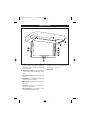
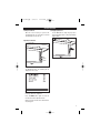
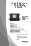
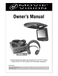
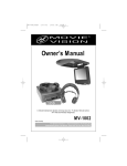
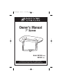
MV750-UM.qxp
6/15/07
11:44 AM
Page 1
Owner's Manual
7'' Screen
AV
AV
MENU
Model: MV750G (Gray)
MV750T (Tan)
For operational or technical assistance, after reading this manual,
please call us toll free at (800) 638-3600 or visit www.magnadyne.com
MV750-UM.qxp
6/15/07
11:44 AM
Page 2
Monitor Functions
9
8
1
7
6
AV
2
AV
MENU
5
4
3
1. 3.5mm Headphone Jack: Plug in headphones
to listen to audio output. Note: Headphones
with built-in volume control are required for
proper operation.
2. Audio/Video (2) Input: Use the supplied cable
to connect to an external audio/video source
(AV2).
3. Screen Release Lever: Press it to release the
monitor.
4. DOWN Button: The DOWN button adjust the
monitor’s level in menu mode.
5. MENU Button: Activates the monitor adjustment menu.
6. UP Button: The UP button adjusts the monitor’s level in menu mode.
7. AV Input Button: Press this button to select
between Audio/Video Input 1 and 2.
2
8. Dome Light Switch: Use this switch to select if
the dome lights are: off, automatically turn on
when the door is opened or on.
9. Dome Lights
MV750-UM.qxp
6/15/07
11:44 AM
Page 3
Screen Functions
Turning the Unit On:
Changing Input Source
When the screen housing is open the unit
automatically turns on. Closing the screen will
automatically turn the unit off.
Use the AV button to change the play source
between Auxiliary Input 1 (AV1) and Auxiliary
Input 2 (AV2).
Adjusting the Monitor:
Up
Menu
Down
Press the MENU button to activate the monitor adjustment menu. The following will be
displayed on the screen:
Use the UP and DOWN buttons on the screen
housing to adjust the brightness.
Press the MENU button again to select the
next desired monitor adjustment item.
Wait 10 seconds and the menu will automatically disappear.
3
MV750-UM.qxp
6/15/07
11:44 AM
Page 4
Screen Functions
Screen’s Remote Eye:
Screen’s Dome Light:
Point your DVD player's remote control at the
MovieVision screen's remote eye to control
player. The screen will receive the signal and
send it directly to the player. *Screen's remote
eye output cable must be connected to DVD
player to enable this feature.
Dome Light
Switch
Remote Eye
Dome Light Switch: The dome light switch is a 3position switch: Off, domelight turns On when
the door is opened and On.
On
Screen’s Wireless Transmitter Module:
Screen’s Wireless
Transmitter Module
Optional IR
Headphone
Model: HP-400
4
Door
Off
MV750-UM.qxp
6/15/07
11:44 AM
Page 5
Wiring Diagram
Audio Output (Female RCA)
Male-to-Male Cable
(Not Supplied)
Optional FM Transmitter
(Model: MV-TX2)
or other
Transmitter Device
Audio/Video Input 1 (Female RCA)
Yellow (VIDEO IN)
White (L-AUDIO IN)
Red (R-AUDIO IN)
Audio/Video Input 2* (Female RCA)
Yellow (VIDEO IN)
White (L-AUDIO IN)
Red (R-AUDIO IN)
or
Audio/Video Input 2* (Female RCA)
Yellow (VIDEO IN)
*Note: If external cable is used
for Audio/Video Input 2 the
internal Audio/Video Input 2
RCA’s will not function.
Red Wire - Ignition
White (L-AUDIO IN)
Red (R-AUDIO IN)
1A
Black Wire - Ground
Yellow Wire - Battery
3A
White Wire - Negative Domelight Door Trigger
Remote Eye Connection
DVD PLAYER
(Cable Supplied)
(Not Supplied)
Note: When creating passage holes for the power wires, use grommets to eliminate any sharp edges
made during drilling. This will protect the wires from being nicked, causing a short circuit.
5
MV750-UM.qxp
6/15/07
11:44 AM
Page 6
Installation
1
Ceiling Support
Beam
2a
Roofmount without Intsallation Shroud
Side st
This ts Again g
Moun of/Ceilin
Ro
AV
MODE
Mount support bracket using screws (not
supplied) with the “This Side Mounts
Against Roof/Ceiling” label against ceiling
support beam(s).
Warning: Take extra care to not penetrate
the roof of your car.
2b
Long screw (actual size)
Attach the screen housing to the metal
support bracket using the screws
provided.
Roofmount with Intsallation Shroud
Standoff screw
Insert the standoff screw into the metal
support bracket.
Long screw (actual size)
AV
MODE
6
Attach the screen housing to the metal
support bracket using the screws
provided.
MV750-UM.qxp
6/15/07
11:44 AM
Page 7
Wiring
Power Harness Wiring:
The 3 wire harness provides battery and ignition 12 volts as well as a chassis ground.
Route the power harness to the point in the
vehicle that you will make the connections.
Red Wire: The red wire in the harness should
be connected to a +12 volt power wire that
is turned On and Off by the position of the
ignition key.
Yellow Wire: The yellow wire in the harness
should be connected to a constant +12 volt
wire that is NOT turned On and Off by the
position of the ignition key.
Door Trigger for Dome Light:
Connect the white wire on the to the common
(-) door pin trigger wire that normally activates the factory dome light when any door
is opened. This wire can usually be located at
the dome light harness in the vehicle ceiling.
Other connection points could be as follows:
• At the vehicle door pin (diodes may be
required to tie all door pin wires to make a
common wire)
• At a light in the door or under the dashboard that is on when any door is opened.
Black Wire: The black wire in the harness
should be connected to the chassis of the
vehicle using a ring terminal and self tapping screw or bolt and nut.
Use this Product Safely
Proper Power Supply
This product is designed to operate with a 12
Volt DC, negative ground battery system.
Do not operate screen in manner other than
described in this manual. Doing so may damage
it and may void your warranty.
WARNING: FOR REAR SEAT VIEWING ONLY!
Do not install on dashboard or anywhere else
that would permit monitor to be viewed by the
driver. Screen must never be used in any manner that will distract driver or interfere with the
driver's safe operation of the motor vehicle.
Battery:
Be careful not to run down the car battery while
using the monitor while the car is stopped.
Modify:
Do not disassemble or modify the monitor. Doing
so may damage it and voids your warranty.
Heat/Cold Exposure:
Do not let the monitor become hot. If temperature in the car is high or the monitor bas been
exposed to direct sunlight and is hot, lower the
temperature before using it.
In extreme cold temperatures. the movement of
the picture may become slow and the picture
may be dark, but this is not a malfunction. The
set will work once the temperature increases.
Cleaning
Use a soft cloth with some purified water to
clean the screen. Do not use any cleaner or
chemical to clean the screen. Usually, a dry
cloth will do.
Warning
Be careful not to drop or apply undue pressure to
the front panel of monitor. If the screen cracks
due to misuse, the warranty will be voided!
Moisture:
Keep drinks and all liquids away from monitor.
Water may damage the internal circuitry.
7
MV750-UM.qxp
6/15/07
11:44 AM
Page 8
Troubleshooting
Only qualified service personnel can remove
the cover or service this player. Otherwise the
warranty will become invalid.
No Power:
• Check to see if the player is set to “On”.
• Check to see that the power plug of the main
unit is properly connected.
• Check to see if that power to the outlet is
properly working.
No Picture:
• Close the screen, then open it again to turn
“On” the unit.
• Check that the correct Audio/Video input is
selected by pushing the AV button.
• Check the video connection.
No Sound:
• Check audio connections.
• If using a Hi-Fi amplifier, try another sound
source.
Warranty
ONE (1) YEAR LIMITED WARRANTY
Magnadyne Corporation or its authorized agents will within 1 year from the date of sale to you, repair,
replace or refund the retail sales price of said product or any part thereof, at the option of the
Magnadyne Corporation or its authorized agents, if said product or part is found defective in
materials or workmanship, when properly connected and operating on the correct power
requirements designated for the specific product. This warranty and Magnadyne Corporation or its
authorized agents obligations hereunder do not apply where the product was; damaged while in the
possession of the consumer, subjected to unreasonable or unintended use, not reasonably
maintained, utilized in commercial or industrial operations, or serviced by anyone other than
Magnadyne Corporation or its authorized agents, or where the warning seal on the product is broken
or the power and/or plugs are detached from the unit. Magnadyne Corporation or any of its
authorized agents will not assume any labor costs for the removal and re-installation of any product
found to be defective, or the cost of transportation to Magnadyne Corporation or its authorized
agents. Such cost are the sole responsibility of the purchaser.
This warranty does not cover the cabinet appearance items or accessories used in connection with
this product, or any damage to recording or recording tape, or any damage to the products resulting
from improper installation, alteration, accident, misuse, abuse or acts of nature.
MAGNADYNE CORPORATION OR ITS AUTHORIZED AGENTS SHALL NOT BE LIABLE TO ANYONE
FOR CONSEQUENTIAL OR INCIDENTAL DAMAGES OR CLAIMS EXCEPT THOSE ACCORDED BY
LAW. NO EXPRESSED WARRANTY OR IMPLIED WARRANTY IS GIVEN EXCEPT THOSE SET FORTH
HEREIN. NO IMPLIED WARRANTY SHALL EXTEND BEYOND 1 YEAR FROM THE DATE OF SALE.
This warranty extends only to the original purchaser of the product and is not transferable.
Some states do not allow limitations on how long an implied warranty lasts and some states do not
allow the exclusion or limitation of incidental or consequential damages, so the above limitations or
exclusion may not apply to you. This warranty gives you specific legal rights and you may have other
rights that vary from state to state.
Defective merchandise should be returned to the original point of purchase or secondly, to
Magnadyne Corporation, 1111 W. Victoria Street, Compton CA 90220. Return Authorization must be
obtained before sending, or merchandise may be refused.
© Copyright 2007
Magnadyne Corporation
MV750-UM
Rev. A 06-15-07