1
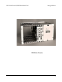
User Manual
Canoga Perkins
2201 Rack Chassis
2200R Redundant
Modem Card
Canoga Perkins
2201 Rack Chassis/2200R Redundant Card
NOTICE
Canoga Perkins reserves the right to change or update the contents of this manual
and to change the specifications of its products at any time without prior notification.
Every effort has been made to keep the information in this document current and
accurate as of the date of publication or revision. However, no guarantee is given or
implied that the document is error free or that it is accurate with regard to any specification.
Canoga Perkins has prepared this manual for use by customers and Canoga Perkins
personnel as a guide for the proper installation, operation and/or maintenance of
Canoga Perkins equipment. The drawings, specifications and information contained
in this document are the property of Canoga Perkins and any unauthorized use or
disclosure of such drawings, specifications and information is prohibited.
Canoga Perkins Corporation
An Inductotherm Company
20600 Prairie Street
Chatsworth, CA 91311-6008
(818) 718-6300
FAX: (818) 718-6312
Web Site: www.canoga.com
e-mail: [email protected]
Copyright 1994, 1995, 1996, 1997, 1999, 2001 Canoga Perkins
All Rights Reserved
2201 Rack Chassis
2200R Redundant Modem Card
User Manual
Part Number 6910040
Rev. F 06/2001
2
2201 Rack Chassis/2200R Redundant Card
Canoga Perkins
2201 Rack Chassis
3
Canoga Perkins
2201 Rack Chassis/2200R Redundant Card
Caution!
This product may contain a laser diode emitter operating at a wavelength of 1300nm 1600nm. Use of optical instruments (for example: collimating optics) with this product
may increase eye hazard. Use of controls or adjustments or performing procedures
other than those specified herein may result in hazardous radiation exposure.
Under normal conditions, the radiation levels emitted by this product are under the
Class 1 limits in 21 CFR Chapter 1, Subchapter J.
ATTENTION!
Cet équipement peut avoir une diode laser émettant à des longueurs d’onde allant de
1300nm à 1600nm. L’utilisation d’instruments optiques (par exemple : un collimateur
optique) avec cet équipement peut s’avèrer dangereuse pour les yeux. Procéder à des
contrôles, des ajustements ou toute procédure autre que celles décrites ci-après peut
provoquer une exposition dangereuse à des radiations.
Sous des conditions normales, le niveau des radiations émises par cet équipement est
en dessous des limites prescrites dans CFR21, chapitre 1, sous chapitre J.
Notice!
This device contains static sensitive components. It should be handled only with
proper Electrostatic Discharge (ESD) grounding procedures.
NOTE!
Cet équipement contient des composants sensibles aux décharges électro-statiques. Il
doit absolument être manipulé en respectant les règles de mise à la terre afin de
prévenir de telles décharges.
4
2201 Rack Chassis/2200R Redundant Card
Canoga Perkins
Table of Contents
1. Description ................................................................................... 7
1.1 2201 Rack Chassis ....................................................................... 7
1.2 2200R Redundant Modem Card ................................................... 7
2. Installation ................................................................................... 8
2.1 2201 Rack Chassis ....................................................................... 8
2.1.1 BR-23 Extender Bracket ......................................................... 10
2.1.2 2201 Power Supplies .............................................................. 11
2.1.3 2201 Chassis Ground Option ................................................... 11
2.2 2200R Redundant Card .............................................................. 12
2.2.1 2200R Remote Control and Failure Alarm ................................ 13
2.2.2 Redundant Card Operation ...................................................... 17
2.2.2.1 2200R Indicator Lights ......................................................... 18
3. Troubleshooting ......................................................................... 19
3.1 2201 Main Power Supply Fuse ................................................... 19
3.2 2201 Secondary Voltage Check .................................................. 19
3.3 2201 Secondary Circuit Fuses .................................................... 20
3.4 2201 Monitor Board .................................................................. 20
3.4.1 Single Power Supply Failure Alarm .......................................... 20
3.4.2 Dual Power Supply Failure Alarm ............................................ 21
3.4.3 Power Supply Remote Failure Alarm Contact ........................... 21
4. Diagnostic Procedures ............................................................... 22
5. Technical Specifications ............................................................ 24
5.1 Power Requirement .................................................................... 24
5.2 Physical Dimensions .................................................................... 24
5.3 Unit Shipping Weights ................................................................. 24
5.4 Operating Environment ............................................................... 24
5
Canoga Perkins
2201 Rack Chassis/2200R Redundant Card
A. Appendix - Limited Warranty ...................................................... 25
List of Figures
2-1 Front View of 2201 Rack Chassis with Modems Installed ............. 8
2-2 Rear View of 2201 Rack Chassis with Modems Installed .............. 9
2-3 BR-23 Extender Bracket and 2201 Rack chassis ........................ 11
2-4 Chassis Ground Option for 2201 ................................................ 12
2-5 2200R Card Positioning ............................................................. 13
2-6 Redundant Modem Card Ribbon Cable Routing ......................... 13
2-7 Alarm Connector Pin Assignments ................................................ 15
2-8 Factory Settings for Internal Jumpers and Switches ..................... 15
3-1 2201 Secondary Power Connector and Slot Assignments ............ 19
List of Tables
2-A 2201 Rack Chassis Factory Settings .......................................... 10
2-B 2200R Redundant Card Factory Settings ................................... 14
6
2201 Rack Chassis/2200R Redundant Card
Canoga Perkins
1. Description
This manual describes the 2201 Rack Chassis used to house card versions of the
2200-series modems and the 2200R Redundant Modem Card, used to facilitate a redundant modem link.
1.1 2201 Rack Chassis
The 2201 Rack Chassis is designed to accommodate up to ten 2200-series modem
cards. However, if MC1 and MC2 interface cards are installed, the 2201 can only
accommodate five modem cards. When full redundant modem links are set up, the
chassis will accommodate three complete links.
The 2201 offers a variety of features and accommodates redundant modem cards with
automatic switchover, local audible/visible and remote power failure alarms, optional
redundant power supplies, and the ability to remove modems from the rack without
powering down the entire system. See Section 2.1 for on installation details
1.2 2200R Redundant Modem Card
The 2200R Redundant Modem Card fits into the 2201, allowing users to configure a
fully redundant fiber optic link. The 2200R is equipped with modem interface extender
cards for easy installation. (See Section 2.2 for installation information.)
7
Canoga Perkins
2201 Rack Chassis/2200R Redundant Card
2. Installation
2.1 2201 Rack Chassis
The 2201 Rack Chassis (see Figure 2-1) is designed for installation in a standard 19inch wide equipment rack. Tabs for standard spacing are provided on each side of the
unit and are predrilled.
The blank panels, modem front panels, power monitor front panel, and power supply
front cover are all equipped with Nylatch retainers.
When installing a modem or panel, the Nylatch should be in an outward or released
condition. Slide the modem card into the rack until it engages fully with the PC board
edge connector, then push the Nylatch retainers in.
To remove a panel or modem, simply pull out on each Nylatch slightly until it clicks;
then, holding onto both retainers, slide the modem from its card guides. The modem
cards and power monitor circuit boards may be removed or installed while the power
supplies are switched on.
The power supplies slide into their compartments in the 2201 from the front of the unit,
after the access cover is removed. On the rear of the power supply is a 10-position
connector which provides the power supply output connection to the backplane
circuit boards (refer to Section 3 for pin configuration).
Figure 2-1.
Front View of 2201
Rack Chassis with
Modems Installed
8
2201 Rack Chassis/2200R Redundant Card
Canoga Perkins
Each supply is held in position with a short extension at the front, which in turn is held
in place with a finger-tightened Allen type bolt. Position “A” (bottom) should be used
when only one supply is being employed.
It will be necessary to first plug the power supply output cables into their respective
sockets on the backplane circuit board. Then the 115/230VAC or ±48VDC power
source should be connected into the rear of each supply.
The power supply monitor card must be installed in the card position farthest to the
right when viewing from the front of the unit (closest to the power supply). A modem
card cannot be installed in this card position, as the interface to the backplane is
different (see Figure 2-2).
The supply-select slide switch (A / A + B) on the circuit board should be positioned
for the number of power supplies used. (For each modem installed in the 2201 Rack
Chassis, a compatible communication cable will be needed, as well as appropriate
fiber optic cables terminated with the appropriate type connectors. Refer to Table 2-A
for factory settings.)
Figure 2-2.
Rear View of 2201
Rack Chassis with
Modems Installed
9
Canoga Perkins
2201 Rack Chassis/2200R Redundant Card
Unit
Setting
Chassis Backplane
W1: Installed
Power Monitor Board
S2: A if single power supply
A+B if redundant power supply
W2: Installed
W4: Installed
2.1.1 FX-23 Extender Bracket
The Canoga Perkins Extender Bracket, FX-23, enables the 2201 Rack Chassis to be
installed in a 23-inch equipment rack. Figure 2-3 shows the FX-23 Extender Bracket
and the rack assembly.
To install the bracket, use the following steps :
Step 1:
Attach the FX-23 Extender Bracket on the left side of the rack assembly
(as viewed from the front) with the appropriate screws. (The FX-23 must
be installed on the opposite side of the power supplies due to weight
considerations.)
Step 2:
Attach the rack assembly to the equipment rack frame with the appropriate screws.
10
Table 2-A.
2201 Rack Chassis
Factory Settings
2201 Rack Chassis/2200R Redundant Card
Canoga Perkins
Figure 2-3.
FX-23 Extender
Bracket and 2201
Rack Chassis
2.1.2 2201 Power Supplies
The 2201 employs either one or two 250 Watt power supplies. They are available in
either 115, 230VAC or ±48VDC configurations.
The optional second power supply (in the B or Upper position) for the 2201 is redundant with, or a backup for, the standard supply and is a duplicate in terms of power
output. When dual power supplies are employed, both supplies provide power to the
modem PC cards at the same time. This reduces the operating load on each supply. If
one power supply fails, the other will continue to power the system and an audible
and/or visual alarm will come on the Power Monitor Card.
2.1.3 2201 Chassis Ground Option
The chassis ground is provided by the AC inlet center pin or the DC input terminal,
labeled GROUND.
The power supply signal ground circuit can be tied together with the 2201 chassis
ground by applying a jumper plug at position W2 on the power distribution circuit
board (see Figure 2-4).
11
Canoga Perkins
2201 Rack Chassis/2200R Redundant Card
Figure 2-4.
Chassis Ground
Option for 2201
2.2 2200R Redundant Card
NOTE: The 2200R can be used with all 2200 series modems except
the 2245 and 2262 modem cards. When used with the 2270 or
2290, flow control operation is not possible.
Redundant fiber-optic links can be established with any of the applicable modem
types. Two modem cards are interconnected to a third plug-in card called the 2200R
Redundant Modem Controller Card (see Figure 2-5). Special Interface boards, Redundant Paddle Boards (Model designation RPB for 2260s, 2270s and 2290s; 4PB for
2240s), are substituted for the normal I/O boards in the two modems. These RPBs
simply buffer the I/O signals between each modem and the 2200R board. The I/O
board which would otherwise have been plugged into the modem is instead mounted
in the 2200R card. Thus, while the fiber-optic link is redundant, the I/O card function
is not. The 2200R Modem Controller card connects to the two modem cards through
the edge connector on the RPB interface cards via ribbon cables. See Figure 2-6. The
2200R Modem Controller Card provides all the multiplexing, buffering and switchover
logic to implement the redundant fiber optic link. (Refer to Table 2-B for 2200R factory
settings.)
When using the 2200R in the 2201, up to three redundant fiber optic links can be used.
For each fiber redundancy, two modem cards and one 2200R card are required. Modems must be installed adjacent to the 2200R being used in that link and the 2200R in
a slot between the two modem cards it serves. Keyed ribbon cables are provided for
modem connection.
12
2201 Rack Chassis/2200R Redundant Card
Canoga Perkins
Figure 2-5.
2200R Card
Positioning
Figure 2-6.
Redundant Modem
Card Ribbon Cable
Routing
13
Canoga Perkins
SW2-1
SW2-2
SW2-3
SW2-4
W2:
W3:
W8:
2201 Rack Chassis/2200R Redundant Card
SIMPLEX
EXT CLK
SYNC
SP1
2240
OTHER
MODEMS
OPEN
OPEN
CLOSED
OPEN
OPEN
OPEN
OPEN
OPEN
INSTALLED
INSTALLED
INSTALLED
INSTALLED
INSTALLED
INSTALLED
The primary modem should be connected to the J-1 ribbon cable, and the secondary
modem should be connected to the J-2 ribbon cable.
The ribbon cables are keyed to provide proper pin alignment. They will connect
properly with folds, and can be tucked between cards.
Connect the fiber optic cables from the local primary transmitter to the remote primary
receiver and from the remote primary transmitter to the local primary receiver. Do the
same for the secondary modem optics.
2.2.1 2200R Remote Control and Failure Alarm
The remote alarm connector (J5) provides both remote control switching and optical
link failure alarm contacts (see Figure 2-7). The automatic mode can be remotely
overridden between the primary and secondary link by utilizing these contacts.
Two jumpers are provided (W1 through W4) for configuring different alarm modes
(see Figure 2-8). W2 and W3 are factory installed for a normal alarm condition and
reflect either a fiber or modem failure. This jumper combination sets the alarm relay
into a normally open condition. It will close on alarm or power loss.
If a switchover occurs while in automatic mode, the alarm indicator on the modem
front panel will light. The jumper combination of W1 and W3 will configure the alarm
relay into a “normally closed” condition. A contact for a remote indication of this
condition is supplied at positions J5-1 and J5-2.
14
Table 2-B.
2200R
Redundant Card
Factory Settings
2201 Rack Chassis/2200R Redundant Card
Canoga Perkins
Figure 2-7.
Alarm Connector
Pin Assignments
To reset the alarm, switch to the active link (Pri or Sec) and switch it back to the AUTO
Mode position.
Switch SW2 is used to configure the redundant switching logic to deal with various
modes of system operation.
Figure 2-8.
Factory Settings for
Internal Jumpers and
Switches
15
Canoga Perkins
2201 Rack Chassis/2200R Redundant Card
SW2-1 (SIMPLEX)
This switch is only closed when the system is set up for
Simplex operation (data transmission in one direction
only). Only the switch at the transmit end is closed.
SW2-2 (EXTCLK)
This switch determines whether both directions of data
flow will be switched together or not. When SW2-2 is
OPEN, both directions of data flow switch together
(operations on both primary modems or both secondary
modems). With the switch closed, the primary modems
can be sending data in one direction while the secondary modems are sending data in the other direction. If
the modems are configured for INTERNAL CLOCK,
SW2-2 must be open. Either position of this switch may
be used for EXTERNAL CLOCK operation with the
resulting switching differences described above. For the
sake of simplicity, it is recommended that this switch be
left in the OPEN position.
SW2-3 (SYNC)
This switch must be set to the OPEN position for all
modem types except the 2240. For use with 2240s,
SW2-3 must be CLOSED.
SW2-4 (SP-1)
This is a spare switch.
NOTE: For Models 2270 and 2290, if the internal clock mode is
configured, the flow control option on the modems must be en
abled. The flow control operation of the modem is required for
proper redundant switching.
Two jumpers are provided, W7 and W8, for configuring chassis ground connections.
Jumper W7 connects signal ground to chassis ground. Jumper W8 allows the signal
ground to float. Note that the W2 jumper on the power distribution board can override
the W7/W8 jumper. Refer to Section 2.1.2 for more information.
16
2201 Rack Chassis/2200R Redundant Card
Canoga Perkins
2.2.2 Redundant Card Operation
The 2200R Series Redundant Card allows a single data electrical interface to be shared
between two fiber links.
This model can be operated in three modes: Remote control, Manual control, and
Automatic. In the Remote control mode, two inputs are provided to permit forcing the
modems to receive on either the primary or secondary link. Transmission occurs only
over the selected link.
The Remote control mode will override either the Manual or Automatic mode. If
Remote operation is not desired, leave the remote inputs unconnected.
To force operation to the primary link, connect the secondary input LOW (LOW =
short to ground, TTL low or RS-232 OFF [negative voltage]) while leaving the primary
input HIGH (HIGH = leave floating, TTL high or RS-232 ON [positive voltage]). To
force operation to the secondary link, connect the primary input LOW, while leaving
the secondary input HIGH.
When not in the Remote control mode, the operating mode is selected by a three
position switch: Primary, Secondary, and Automatic.
The “Primary” and “Secondary” switch positions represent the Manual mode,
which functions exactly as does the Remote control mode. In the Manual mode, the
modem will transmit and receive only on the link selected.
The “Automatic” switch position forces the Automatic mode of operation, the default
operating mode.
17
Canoga Perkins
2201 Rack Chassis/2200R Redundant Card
NOTE: For use with the Model 2240 Modem only, the Automatic mode
requires the CD/DCD switch on the Modem card to be OFF
and the CD/SYNC to be ON. These are the factory defaults for
the 2240.
In this mode transmit optical energy is applied to both links while the link chosen for
reception is arbitrary, as the active link is determined by the last link selected in the
Manual or Remote control modes immediately before switching to the Automatic
mode.
Thereafter, each end will independently switch links (receive only if EXTCLK [SW22] = CLOSED and modem is in EXTCLK mode) when its Carrier Detect signal turns off
(indicating a link failure). If SW2-2 is in the OPEN position, both directions of the link
will switch. If SW2-2 is in the CLOSED position, only the receive link will switch. The
carrier detector is a function of receive optical power and presence of clock from the
other end. If both links exhibit significant interruptions of Carrier Detect, the modems
will switch back and forth between the primary and secondary links until one modem
turns on its Carrier Detect.
2.2.2.1 2200R Indicator Lights
Four LEDs are provided on the 2200R to indicate the activity state of the redundant
link.
Pwr
The first LED is Power ON.
Aut
The second LED is an operating mode indicator. “ON” indicates
operation in the Auto mode. When this LED is off, the mode is
indicated by the mode select switch position.
Sec Rcv
The third LED defines the link being used for receiving (Secondary
receiver “ON” represents the secondary link).
Alm
The fourth LED is an alarm indicator and is turned ON if an automatic switchover occurs while the 2200R is in the Automatic mode.
This implies trouble on the other link. A dry relay contact for a
remote alarm is also provided to indicate this occurrence. This LED
and alarm relay contact are reset whenever the modem is switched
into the Remote control or Manual mode.
18
2201 Rack Chassis/2200R Redundant Card
Canoga Perkins
3. Troubleshooting
The following procedures are intended for use in the event of a system failure, not
during the initial installation of a Modem optical link. For initial installation checkout,
refer to Section 2 of this manual. Refer also to Section 4 for detailed diagnostics.
3.1 2201 Main Power Supply Fuse
To replace the main power supply fuse, remove the unit’s Main power cord from its
socket or terminal block at the base of the supply. The fuse cartridge is located
directly above the low voltage output cable. It is of the bayonet type, so a slight
inward pressure and a counter clockwise twist will release the fuse. Replace a blown
main power supply fuse with a same rate “Slo-Blo” type as indicated by the fuse
rating label on the blown fuse holder.
3.2 2201 Secondary Voltage Check
When making a voltage check of the supply’s secondary circuit, use the AC setting
for AC power supply or DC setting for DC power supply on your voltage meter. See
Figure 3-1 for secondary power connector and slot assignments. The measured voltage between the two contacts for a specific group of card slots, positions 3 and 4 for
example, should be 18VAC or 18VDC. The measured voltage between pin 1 (or pin 9 or
pin 10), the return circuit, and any other pin position should be 9VAC , +9VDC or 9VDC. All the measured voltages can be within ±10%.
Figure 3-1.
2201 Secondary
Power Connector
and Slot Assignments
19
Canoga Perkins
2201 Rack Chassis/2200R Redundant Card
NOTE: On older units, only eight pins (pin 1-8) were used. However,
old connectors are compatible with new plugs, and vice versa,
due to the location of the key.
3.3 2201 Secondary Circuit Fuses
There are six fuses employed inside each rack chassis power supply. Each protects
one of the secondary circuits leading to the modem positions.
WARNING!
Be certain that the main power cord is disconnected when
accessing the internal fuses.
To access these fuses, remove the retaining screws that hold the power supply cover
in position. The fuses are positioned on each side of the supply in groups of three.
They may be removed for inspection, and/or replacement. Replace with the same
rating of fuses.
3.4 2201 Monitor Board
3.4.1 Single Power Supply Failure Alarm
If the 2201 employs only one power supply monitor board (in the A or Lower position),
and one of its output circuits fails, an audible warning will sound. This will cause the
failure indicator for power supply “A” to light.
The audible warning will continue until the “Alarm Reset” button is pressed. This
does not cure the problem, so the power supply should be repaired or replaced. The
failure indicator will continue to be lit until the supply failure is corrected.
When the above type failure occurs, the entire system may be partially affected. Note
which modems in the rack do not have “Power On” indicators lit then identify the card
positions. Every power supply contains three secondary output circuits to feed the
2201 backplane (card positions 1, 2 and 3 are on one circuit; 4, 5 and 6 on another; and
positions 7 through 10 are on yet another).
If the 2201 has empty card positions, modems residing in the affected positions may
be moved to non-affected positions. If extra card positions are not available, the
modems affected should be put out of service until the supply is replaced.
20
2201 Rack Chassis/2200R Redundant Card
Canoga Perkins
3.4.2 Dual Power Supply Failure Alarm
When dual power supplies are employed in the 2201, the backup supply will continue
to power the modems after a failure of the other supply. Press the “Alarm Reset”
button to disable the audible alarm; the “Unit A Fail” or “Unit B Fail” indicator will
stay lit until the defective power supply is removed from the system and replaced.
The failed supply may be removed from the 2201 and replaced without taking the
modems out of service. The power supply line cord must be removed, as well as the
secondary supply lines to the power supply monitor PC card. The failed power
supply may then be removed from the front of the rack mount unit.
3.4.3 Power Supply Remote Failure Alarm Contact
The 2201 provides an external alarm contact. This floating relay contact is incorporated into the power supply monitor PC card. Access to this circuit is via a twoposition pluggable terminal strip directly below the power input connectors on the
2201 backplane circuit board.
The standard factory configuration for this alarm relay is a “normally open” condition. There is a jumper setting on the power supply monitor board to provide a “normally closed” condition (W1 for “normally closed,” W2 for “normally open”).
The standard factory setting of the remote alarm function is to activate the relay
contacts whenever a power supply (either “A” or “B”) has failed, or if power is
completely lost. This relay will not return to normal until the problem is corrected.
21
Canoga Perkins
2201 Rack Chassis/2200R Redundant Card
4. Diagnostic Procedures
The following diagnostic procedures assume that at least one modem is installed in
the 2201 to be able to troubleshoot and isolate a defective modem, power supply or
monitor card.
Required Equipment
• Multimeter - (for voltage, resistance and continuity tests)
Step
Symptom
Possible Cause(s)
Action
1
No power indicator
on front panel(s).
Power indicator
out on R/M supply.
No Main power
Check Main power
source.
2
Same as Step 1
Blown Main fuse
Remove power and
check Main fuse at
rear of power
supply.
3
No power indicator
on front panel(s).
Power indicator
lit on R/M supply.
Failure indicator
lit on 2201 Power
Monitor Board.
Blown secondary
fuses
Check secondary
fuses. See section
3.3.
4
Same as Step 3, but
fuses are good.
Low voltage output
Go to Step 7.
5
If any fuse is bad, replace it with a good fuse of the proper rating. If the
power supply still blows the fuse, unplug all the cards from the chassis,
replace the defective fuse, and turn on the power. If the fuse still blows,
replace the chassis.
22
2201 Rack Chassis/2200R Redundant Card
Canoga Perkins
Step
Symptom
Possible Cause(s)
Action
6
Replace any bad fuses with good fuses of the proper rating. With the
power on, insert the cards into the chassis, one at a time. Replace any
cards that cause the power supply to fail. Replace power supply fuses as
necessary. Proceed to Step 7.
7
Check the secondary power supply voltages as described in Section 3.2 of
the manual. If anyvoltage is bad, replace the power supply.
8
Same as Step 4, but
output voltage is
normal.
Bad modem
Return modem for
repair.
9
Failure indicator lit
on 2201 power monitor
card. All front panel
power indicators lit.
All units functioning.
Low input voltage
Check main power
source.
10
"
"
"
Output low voltage
caused by bad modem.
Perform Step 6.
11
"
"
"
2201 monitor card
switch set wrong
12
"
"
"
Bad monitor card
Replace supply
monitor card.
23
Canoga Perkins
2201 Rack Chassis/2200R Redundant Card
5. Technical Specifications
5.1 Power Requirement:
2201 Rack Chassis
115VAC +10%, 2.2 Amps, 47-63Hz
Optional:
• 230VAC +10% @ 1.1 Amps,
47-63Hz
• ±48VDC, 5Amps
5.2 Physical Dimensions:
2201 Rack Chassis Enclosure
19” W x 12.8” D x 8.8” H
5.3 Unit Shipping Weights:
2201 Power Supply Monitor Card
2201 AC Power Supply
2201 DC Power Supply
2201 Rack Chassis
0.50 pounds
9.00 pounds (each)
3.00 pounds (each)
7.70 pounds (empty)
5.4 Operating Environment:
Temperature
Humidity
24
0° to 50° C
0 to 95% (non-condensing)
2201 Rack Chassis/2200R Redundant Card
Canoga Perkins
Appendix A
Limited Warranty
A.1
Products
Canoga Perkins warrants that, at the time of sale, its products will be free
from defects in material and workmanship, and if properly installed and
used will substantially conform to Canoga Perkins’ published specifications.
Subject to the conditions and limitations set forth below, Canoga Perkins
will, at its opinion, either repair or replace any part of its product(s) that
prove defective by use of improper worksmanship or materials. This
warranty does not cover any damage to products that have been subjected
to lightning damage or other Acts of Nature, misuse, neglect, accident,
damage, improper installation or maintenance, or alteration or repair by
anyone other thanCanoga Perkins or its authorized representative. Customer must notify Canoga Perkins promptly in writing of any claim based
on warranty. Canoga Perkins is not liable for, and does not cover under
warranty, any costs associated with service and/or the installation of its
products of for any inspection, packig or labor costs in connection
withreturn of goods. In the event Canoga Perkins breaches its obligation of
warranty, customer sole and exclusive remedy is limited to replacement,
repair, or credit of the purchase price, at Canoga Perkins’ option.
A.2
Duration of Warranty
Three-year Warranty: This product is covered by this warranty for a period
of three (3) years from the date of shipment.
A.3
Limitations
Canoga Perkins may at its sole discretion modify its Limited Warranty at
any time and from time to time.
25
Canoga Perkins
2201 Rack Chassis/2200R Redundant Card
Other than those expressly stated herein, THERE ARE NO OTHER
WARRANTIES OF ANY KIND, EXPRESSED OR IMPLIED, AND
SPECIFICALLY EXCLUDED BUT NOT BY WAY OF LIMITATION,
ARE THE IMPLIED WARRANTIES FOR FITNESS FOR A PARTICULAR PURPOSE AND MERCHANTABILITY. IT IS UNDERSTOOD
AND AGREED CANOGA PERKINS' LIABILITY WHETHER IN
CONTRACT, IN TORT, UNDER ANY WARRANTY, IN NEGLIGENCE OR OTHERWISE SHALL NOT EXCEED THE AMOUNT OF
THE PURCHASE PRICE PAID BY THE PURCHASER AND UNDER
NO CIRCUMSTANCES SHALL CANOGA PERKINS BE LIABLE
FOR SPECIAL, INDIRECT, INCIDENTAL OR CONSEQUENTIAL
DAMAGES. THE PRICE STATED FOR THE EQUIPMENT IS A
CONSIDERATION IN LIMITING CANOGA PERKINS' LIABILITY.
NO ACTION, REGARDLESS OF FORM, ARISING OUT OF THE
TRANSACTIONS OF THIS AGREEMENT MAY BE BROUGHT BY
PURCHASER MORE THAN ONE YEAR AFTER THE CAUSE OF
THE ACTION HAS ACCRUED. CANOGA PERKINS' MAXIMUM
LIABILITY SHALL NOT EXCEED AND CUSTOMER'S REMEDY IS
LIMITED TO EITHER (i) REPAIR OR REPLACEMENT OF THE
DEFECTIVE PART OF PRODUCT, OR AT CANOGA PERKINS'
OPTION (ii) RETURN OF THE PRODUCT AND REFUND OF THE
PURCHASE PRICE, AND SUCH REMEDY SHALL BE
CUSTOMER'S ENTIRE AND EXCLUSIVE REMEDY.
A.4
Customer Service Department Repair Warranty
Repairs performed by the Canoga Perkins Customer Service Department
will be free from defects in material and workmanship for a period of ninety
(90) DAYS from the date the repaired product is shipped, or until the
expiration of the original factory warranty, whichever is longer.
Shipping charges to Canoga Perkins will be at customer's expense. Units
will be returned to the customer FOB origin. Repaired units will be returned
to the customer by standard ground shipment unless otherwise specified,
with any additional costs for customer specified expedited delivery at the
customer’s expense.
26
2201 Rack Chassis/2200R Redundant Card
A.5
Canoga Perkins
Return Policy
Customer must obtain an RMA (Return Material Authorization) number
from the Canoga Perkins Customer Service Department (818) 718-6300
prior to returning a product for service or repair.
If the product's warranty has expired, customer must provide the Canoga
Perkins Customer Service Representative with a Purchase Order to
authorize the repair.
Whenever possible, products should be returned in the original shipping
carton or packaging with a description of the failure and results of any
diagnostic testing included.
CANOGA PERKINS CORPORATION
Customer Service Department
20600 Prairie Street
Chatsworth, California 91311-6008
Business (818) 718-6300
(Monday through Friday 7 a.m. - 3:30 p.m. Pacific Time)
FAX (818) 718-6312 (24 hrs.)
24 Hour Emergency Repair Hot Line
(800) 360-6642
27