1
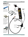
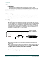
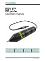
Corrosion testing probes
ROV-II™
CP probe
Operation manual
Twin reference
electrodes for
online calibration
Can be used with
ROVs or as a
diver-held probe
Works as either
a contact or
proximity probe
Use with Polatrak
Deep C Meter™
for subsea readout
Deepwater Corrosion Services Inc. | 10851 Train Court, Houston, TX 77041 USA +1 (713) 983 7117 | Email: [email protected] | polatrak.com
©
2013 Deepwater Corrosion Services Inc. Specifications subject to change without notice
Document 354-MN01-ENG Rev. C
ROV-II operation manual
Table of contents
1. ROV-II components
3
2.1 MSDS sheets
4
4. Installation procedure
4
4.2 ROV installation
5
5. Calibration
6
5.2 Using calibration for troubleshooting
6
5.4 Subsea calibration
7
6. Operation
8
6.2 Recording cathodic protection potentials
8
8. Data interpretation
9
2. Reference documents
4
3. Health and safety
4
4.1 Dive spread
4
4.3 Cautionary notes
5
5.1 General
6
5.3 Topside/bucket calibration
6
5.5 Proximity mode ground check
8
6.1 Wet check
8
7. Taking cathodic protection potential readings
9
9. Maintenance and repair
10
9.2 Reference electrode element replacement
10
9.1 Tip replacement
10
10.Troubleshooting
11
List of figures
Figure 1 Soft-splicing the whip onto the comms cable
Figure 2 SEA CON® RMG-3FS connector pin diagram
Figure 4 Calibration vs. zinc coupon
12
Figure 6 Calibration vs. master Ag/AgCl electrode
14
Figure 8 Wiring schematic for Deep C Meter™ readout
16
4
7
Figure 3 Identifying a failed reference electrode
8
Figure 5 Calibration cell-to-cell
13
Figure 7 Wiring schematic for diver-assisted platform survey
15
List of tables
Table 1 Normal cathodic protection ranges for bare carbon steel in seawater
9
Table 2 Troubleshooting quick guide
11
www.polatrak.com | 10851 Train Court, Houston, TX 77041 USA | Telephone: +1 (713) 983 7117 | Email: [email protected]
©
2013 Deepwater Corrosion Services Inc. Specifications subject to change without notice
2
Document 354-MN01-ENG Rev. C
ROV-II operation manual
ROV-II™
Tip
Components
Nose cone
assembly
An offshore case is
provided with the ROV-II.
The case can be filled
with seawater so that the
probe can be calibrated.
Housing
Reference
electrode
element
Whip
SEA CON®
RMG-3FS
connector
T-handle probe mounts
are available for use with
ROVs. There’s a stainless
steel version (above right)
with a shock absorber
to protect the probe
during stabbing, and
another made of Delrin
so inspection-class ROVs
can handle their weight.
Both are available with
fish-tail handles.
Serial
number
Reference
electrode
element
Tail assembly
Hex screws
The Deep C Meter™ LED
readout can be used with
the ROV-II to record readings without utilizing the
ROV’s umbilical.
www.polatrak.com | 10851 Train Court, Houston, TX 77041 USA | Telephone: +1 (713) 983 7117 | Email: [email protected]
©
2013 Deepwater Corrosion Services Inc. Specifications subject to change without notice
3
Document 354-MN01-ENG Rev. C
ROV-II operation manual
2. Reference documents
2.1MSDS sheets
2.1.1 Dow Corning – 4 Electrical Insulating Compound MSDS – connector sealant
http://www.dowcorning.com/applications/search/products/details.aspx?prod=01903128&type=prod
PLEASE CONTACT YOUR POLATRAK REPRESENTATIVE FOR ANY QUESTIONS AND/OR ISSUES
REGARDING THIS MANUAL.
3. Health and safety
It is the intention of Deepwater Corrosion that all test and inspection procedures are carried out in
a safe manner in accordance with the Health and Safety At Work Act and any other relevant legislation. If required by the client, Deepwater personnel will attend any site safety induction courses
before carrying out work on-site.
4. Installation procedure
4.1 Dive spread
4.1.1 When used with diving operations, assemble a cable with a SEA CON® RMG-3FS connector at the subsea end. In our experience, the most suitable cable is the four (4) conductor armored
spiral comms cable used by most divers for diver communications; it has two twisted pairs and
is very rugged. A whip with this connector is provided with the probe and should be soft-spliced
onto the end of the comms cable (see Fig. 1). Ensure that the connection is taped back to the
armored wire to provide strain relief to the subsea connector.
Figure 1 - Soft-splicing the whip onto the comms cable
Comms cable
To topside digital voltmeters or LED readout
SEA CON® RMG-3FS
connector
Soft splice
Tail assembly
6’ Whip
ROV-II
4.1.2 If required, Deepwater Corrosion can provide a complete assembly on a 500-foot-long
umbilical cable.
4.1.3 The appropriate length of cable should be married into the dive hose, leaving 4-6 feet (1.2m
– 2m) of slack at the subsea end and at least 50 feet (15m) at the topside end. Always install
the dummy plug on the connector when the probe is not attached.
4.1.4 The topside end of the cable will be run to the dive control area along with the platform
ground cable and any ground from pipeline risers. The connections can be made to a pair of digital multimeters (refer to fig. 6, wiring schematic for diver-assisted platform survey.)
www.polatrak.com | 10851 Train Court, Houston, TX 77041 USA | Telephone: +1 (713) 983 7117 | Email: [email protected]
©
2013 Deepwater Corrosion Services Inc. Specifications subject to change without notice
4
Document 354-MN01-ENG Rev. C
ROV-II operation manual
4.2 ROV installation
4.2.1 The probe is best installed in or on a manipulator but may be attached directly to the ROV
frame if there is no manipulator available. (This should be done when only proximity readings are
required).
4.2.2 The recessed grooves in the probe body may be used to accommodate stainless steel
hose clamps for attachment. We recommend installing neoprene rubber pads between the probe
and the mounting surfaces and attaching a safety line to the probe. This will provide a better attachment and some degree of compliance.
4.2.3 A male SEA CON® RMG-3FS connector on a 6’ (2m) whip is provided to facilitate splicing
into the ROV junction box.
4.2.4 Routing the two reference electrode wires in a shielded twisted pair in the ROV umbilical is recommended. The tip wire can be connected to a coaxial cable or any other cable that is
straight-through to the control van with no breaks.
4.2.5 Topside, the system can be wired directly to a pair of digital multimeters (Fig. 7) or a Polatrak Deep C Meter (Fig. 8). It can also be wired directly into a video annotator with an input impedance of at least 1 MΩ
4.3 Cautionary notes
Polatrak sintered silver / silver chloride reference electrode elements are designed to be rugged, but
they are consumables that have a given operational life. The life of these electrodes can be extended
to several seasons if the following care is taken:
4.3.1 Never allow the electrode elements to be directly shorted to ground or any other metallic
object when immersed in seawater.
4.3.2 Never use the electrode subsea with the underwater connector un-mated.
4.3.3 Never read the ROV-II probe with an analog voltmeter. Ensure that high-input impedance
digital equipment is used.
4.3.4 Never handle the bare reference electrode element (small gray pellet) with bare hands.
4.3.5 Do not use any type of solvent or detergent on the probe. Rinse only in fresh water after
every operation.
4.3.6 Never immerse the electrode in anything but fresh water or seawater.
4.3.7 Never allow a connector or bulkhead to be immersed unless it is mated or has a sealing
dummy plug inserted.
4.3.8 Never read the electrode on a multimeter scale other than DC Volts.
4.3.9 When not in use, store the probe in the provided container filled with seawater or tap
water. Probe can be stored dry between jobs but should be soaked in fresh water for at least one
hour before storage.
4.3.10 Do not attempt to field-repair any wires on the probe or inside the probe and never attempt
to modify the probe tip in any way.
www.polatrak.com | 10851 Train Court, Houston, TX 77041 USA | Telephone: +1 (713) 983 7117 | Email: [email protected]
©
2013 Deepwater Corrosion Services Inc. Specifications subject to change without notice
5
Document 354-MN01-ENG Rev. C
ROV-II operation manual
5. Calibration
5.1 General
As with any subsea measurement device, it is important to calibrate the ROV-II probe to ensure that
the reference electrodes are working properly and that there is no damage to the probe. If the probe
is not calibrated, readings may be incorrect and the dive may have to be repeated.
Since the ROV-II probe uses two reference electrodes, the user always has two independent voltage
readings of the tip contact. This provides an advantage over probes that use a single reference electrode because the cell-to-cell value can be checked at any time during operation to verify the probe
is calibrated and working properly. The cell-to-cell value is simply the difference in voltage between
the two readings; this value should never exceed 5 mV topside and 10mV subsea. For example, if
both voltage readings are the same, the cell-to-cell value is 0 (zero) mV.
5.2 Using calibration for troubleshooting
Certain problems could cause the probe to be out of calibration. A common cause, particularly on
diver surveys, is damage to the cable insulation. This causes an offset in the voltage readings, which
would usually be interpreted as inadequate protection levels. Other causes include one or more
defective reference cell electrodes, wire damage within the probe or mud that has gotten inside the
probe. Calibration can be used to quickly diagnose a defective reference electrode or cable damage
and should be performed before, during, and after every use.
NOTE: Company calibration specifications must be met, but we strongly advise also using the attached procedures.
5.3 Topside/bucket calibration
There are two types of bucket calibrations that can be performed:
• Zinc coupon calibration
• Cell-to-cell calibration
Wiring schematics for these two bucket calibrations are shown in Figures 4-5.
CAUTION:
Never use a metallic container for storage or for performing calibrations.
5.3.1 Fill a non-metallic bucket or container approximately 18 in. (45 cm) deep with seawater or
simulated solution with a specific gravity between 1.021 and 1.028.
5.3.2 Place the probe in the bucket, allowing the body to fill with seawater. The entire probe,
including the tip, must be immersed.
CAUTION:
DO NOT immerse the Seacon RMG-3FS connector in water unless it is mated with the
dummy plug.
5.3.3 Wait 30 minutes for the electrode elements to reach equilibrium (first time use only).
5.3.4 To perform a zinc coupon calibration:
• Immerse the zinc calibration coupon. Stab the probe tip firmly onto the zinc coupon.
• Using a digital voltmeter set on 2.00 V DC scale, contact pin socket #1 (the large socket; refer
to Figure 2) with the positive voltmeter lead. This pin socket measures the probe tip.
• At the same time, contact pin socket #2 (first clockwise of the large pin socket) with the nega-
www.polatrak.com | 10851 Train Court, Houston, TX 77041 USA | Telephone: +1 (713) 983 7117 | Email: [email protected]
©
2013 Deepwater Corrosion Services Inc. Specifications subject to change without notice
6
Document 354-MN01-ENG Rev. C
ROV-II operation manual
tive lead and note the reading. Then take the negative lead and contact pin socket #3; note the
reading.
• Figure 4 shows the correct wiring schematic and the expected results. The two readings
should not be more than 5 mV apart.
• Remove the probe tip from the zinc coupon. The reading should revert to a voltage within the
range of (-) 0.200 to (-) 0.400 V DC.
5.3.5 To perform a cell-to-cell calibration:
• Using a digital voltmeter set on 200 mV DC scale, contact pin socket #2 with the positive voltmeter lead and pin socket #3 with the negative voltmeter lead. Note the reading.
• Figure 5 shows the correct wiring schematic and the expected results. The reading should be
between ±5 mV.
Figure 2 - SEA CON® RMG-3FS connector pin diagram
Pin socket 1: Contact tip
Pin socket 2: Reference electrode #1 (R1)
Pin socket 3: Reference electrode #2 (R2)
5.4 Subsea calibration
The cell-to-cell value can be checked at any time while the ROV-II probe is deployed subsea.
Subsea calibration should be performed with the entire cable immersed, as it will quickly detect
any cable damage. Diver surveys using the ROV-II probe should have two topside multimeters
connected to the dive cable. ROV-assisted surveys should have the Polatrak Deep C Meter alongside the probe to provide a subsea LED readout of the voltages. Wiring schematics for these two
options can be seen in Figures 7-8.
CAUTION
NEVER submerge any unmated Seacon connectors.
5.4.1 While the probe is free-flying subsea without contacting any metal, the voltage readings
will vary depending on ROV/diver speed, time of immersion and whether the tip contact has
recently stabbed a structure or pipe. Normally, the voltage readings will be in the range of (-) 200
to (-) 400 mV.
5.4.2 Both voltage readings should never be more than 10 mV apart while the probe is subsea.
Remember, this difference between voltage readings is the cell-to-cell value. If the cell-to-cell
value is greater than 10 mV, the cause may be:
• Lead wire is damaged, exposing copper to seawater.
• A connection is not properly mated or is leaking.
• One or more reference electrode elements has failed.
5.4.3 If it becomes apparent in the middle of an operation that one reference electrode element
has failed, it is possible to complete the dive. Follow these steps to isolate the bad reference
electrode:
www.polatrak.com | 10851 Train Court, Houston, TX 77041 USA | Telephone: +1 (713) 983 7117 | Email: [email protected]
©
2013 Deepwater Corrosion Services Inc. Specifications subject to change without notice
7
Document 354-MN01-ENG Rev. C
ROV-II operation manual
• Stab the probe onto the structure and determine which reading displays the most positive
voltage; this is normally the failed reference electrode. The good reference electrode will have the
most negative reading.
For example, (-) 900 mV is more negative than (-) 800 mV. (-) 900 mV would indicate the good
reference electrode; (-) 800 mV would indicate the failed reference electrode.
• Record the cell-to-cell value.
• Only use the voltage readings from the good reference cell for the rest of that dive.
Figure 3 - Identifying a failed reference electrode
Most negative reading:
Indicates good electrode
Most positive reading:
Indicates failed electrode
5.5 Proximity mode ground check
When the probe is being used in proximity mode, the user needs to verify that the platform ground
wire and probe tip will yield the same reading at any point on the main structure.
• Stab the steel structure with the probe and record the voltage reading.
• Take the reading again using the platform reference ground wire instead of the probe tip. The
readings should be identical.
If the readings vary by more than 3 mV, check the platform ground wire connection.
6. Operation
Most companies have their own survey procedures to follow. The following guidelines are given as
guidance only.
6.1 Wet check
6.1.1 When interfaced to an ROV, it’s important to perform a wet check before every dive. Signal errors caused by umbilical power cable interference could introduce reading errors.
6.1.2 With the probe wired to the ROV, immerse the system to a depth of at least –30 feet (–10
m), and with the vehicle still in its Tether Management System (TMS), bring up one electrical system at a time and note the potential of the tip. (It will vary some depending on immersion time).
If there is a problem, the potential will change rapidly or will spike when the circuit is powered.
Repeat for all electrical and hydraulic systems. If a problem is detected, it should be fixed. Usually, the cause is a poor ground connection or a faulty leaking underwater connector. The system
at fault can be switched off if it will not hinder operation.
6.2 Recording cathodic protection potentials
If wired correctly, the cathodic protection potentials should have a negative polarity. Accurate readings will be steady as long as the probe is not moving. If readings are erratic, this is a sign of a connection problem and the cause should be isolated and fixed.
www.polatrak.com | 10851 Train Court, Houston, TX 77041 USA | Telephone: +1 (713) 983 7117 | Email: [email protected]
©
2013 Deepwater Corrosion Services Inc. Specifications subject to change without notice
8
Document 354-MN01-ENG Rev. C
ROV-II operation manual
7. Taking cathodic protection potential readings
Stab the tip-contact probe onto the point on the structure where the reading is required. When a
good contact is made, the displays will show a steady reading.
CAUTIONS
• Avoid stabbing painted or coated surfaces whenever possible. Try to take readings on
bare steel or on spots specially designated for cathodic protection measurement.
• If necessary, anodes can be stabbed. However, it is best to stab the anode band if possible.
• Avoid trying to stab through heavy, hard marine growth.
• The probe unit should be kept out of the mud, which will contaminate the electrodes.
• If the readings are not steady or do not match the criteria in Table 1, the cause is probably due to a high-resistance contact. DO NOT RECORD THESE NUMBERS. Continue to
stab until readings are within the range specified in Table 1. See troubleshooting section if
problems persist.
• NEVER operate the system with any of the connectors un-mated unless the dummy
plugs are installed.
8. Data interpretation
For carbon steel structures in seawater, the readings obtained should be within the ranges in Table
1. Exceptions may occur if the probe is stabbed onto an isolated section of a corrosion-resistant
alloy such as stainless steel, copper or nickel. In these cases, readings less negative than the indicated range may be noted. If so, ensure that the readings are steady and within the ±5 mV allowable
tolerance.
Table 1 - Normal cathodic protection ranges for bare carbon steel in seawater
Range (mV)
Interpretation
Action
-500 or more positive
Error
Remake contact & verify
Measure two other points around the
component
Abort & refer to troubleshooting section
-501 to -649
Isolated from cathodic protection
-650 to -799
Not cathodically protected
-800 to -849
Marginal cathodic protection
-850 to -1049
Cathodically protected
-1050 to -1149
Anode potential
-1150 or more negative
Remake contact & verify
Record data
Record data
Remake contact & verify.
Measure two other points around the
component
Abort & refer to troubleshooting section
Error
www.polatrak.com | 10851 Train Court, Houston, TX 77041 USA | Telephone: +1 (713) 983 7117 | Email: [email protected]
©
2013 Deepwater Corrosion Services Inc. Specifications subject to change without notice
9
Document 354-MN01-ENG Rev. C
ROV-II operation manual
9. Maintenance and repair
This section covers general operational maintenance. Do not attempt any task not described in this
section, as it may damage the system.
9.1 Tip replacement
From time to time it will be necessary to replace tips. Remove the old tip with a 7/16 in. wrench (flats
are best). Avoid using an adjustable wrench if possible. Ensure that the new tip is tight.
CAUTION: The contact tip has been machined to a very sharp point to enable easier readings through coatings. This point can also easily cut or poke through human skin. Please
handle with care.
9.2 Reference electrode element replacement
Spare plug-in electrode elements are available for the ROV-II probe. These elements will also work in
the Polatrak CP Gun. If one element or more needs to be changed, follow this procedure:
9.2.1 Remove the probe from the ROV and un-mate the connector. Install the provided
dummy plug onto the exposed flying lead connector.
9.2.2 Perform a zinc coupon bucket calibration as described in section 5.3.4. The faulty electrode will be the one that gives the more positive reading.
9.2.3 Ensure that the probe is drained of seawater.
9.2.4 Take the probe unit to a clean area.
9.2.5 DO NOT handle the small electrode pellet with bare hands.
9.2.6 Remove the two screws securing the tail unit and gently pull out the tail unit to expose
the electrode elements. Try to avoid un-mating the tip connector.
9.2.7 Visually inspect to ensure that the wire is not damaged and the connector is properly
mated.
9.2.8 Remove the bad electrode and discard according to appropriate local environmental
procedures.
9.2.9 Take the new electrode and carefully place a small amount of insulating compound on
the sealing section of the electrode connector. Please refer to the MSDS in appendix before
handling sealant. All appropriate Personal Protective Equipment (PPE) shall be worn, including
safety glasses, as a minimum.
9.2.10 Plug in the new electrode.
9.2.11 Check that all connectors are fully mated, then carefully put the electrodes back into the
housing and re-attach the tail unit and nose cone.
9.2.12 Repeat calibration as described above. (Note that a new dry element may take up to 30
minutes to reach equilibrium)
Caution: NEVER immerse an electrode element in water with the connector pin exposed.
www.polatrak.com | 10851 Train Court, Houston, TX 77041 USA | Telephone: +1 (713) 983 7117 | Email: [email protected]
©
2013 Deepwater Corrosion Services Inc. Specifications subject to change without notice
10
Document 354-MN01-ENG Rev. C
ROV-II operation manual
10. Troubleshooting
10.1 The cell-to-cell value is greater than 5 mV topside or 10 mV subsea
The problem could be one of the following:
• One reference electrode has failed.
Repeat the bucket calibration (section 5.3). The electrode with the more positive reading is probably in error. Replace the reference electrode element (section 9.2).
• There is damage to the tail assembly cable or umbilical cable.
When recovering the ROV-II Probe from the dive, any cable damage can be quickly located and
repaired. Monitor the cell-to-cell value as the cable comes out of the water. If the problem is cable
damage, the cell-to-cell value will revert to the acceptable range (10 mV or less) as soon as the
damaged area of cable clears the water.
10.2 Both displays reading low (more positive) voltages
If both electrodes read low during a stab (more positive than (–)500 mV), the problem is probably
with the contact tip wire attached to the nose cone assembly. If the tip wire is damaged, a temporary
soft-splice repair can be made using ScotchKote® sealant (not included) and splicing tape. However, prolonged operation in this manner is not recommended. Order a new nose cone assembly as
soon as possible.
10.3 Recalibration
After any replacement or repair, recalibrate the instrument by performing a bucket calibration as
described in section 5.3.
Table 2 - Troubleshooting quick guide
Symptom
Instrument will not calibrate
Both electrodes reading low
Possible problem
Action
One electrode is bad
See section 9.2
Zinc coupon is passivated
Remove zinc and clean with rasp
Electrodes are dry
Soak in seawater for 30 minutes and retry
Tip wire damaged
Remove probe tail unit, unplug tip wire,
remove nose cone, inspect tip wire and
repair with ScotchKote as temporary
measure. Order replacement nose cone.
Readings are not steady and Voltmeter batteries are low
continue to change.
Poor structure contact
One reading suddenly goes
less negative
Deep C Meter LED readouts
are blank
Replace voltmeter batteries
Re-stab to ensure contact.
Connector is flooded
Check connectors
Lead wire (flying lead) is nicked.
Inspect and repair / replace as necessary
Not enough light to photo-cell
Increase light intensity and re-direct to
center of lens.
Batteries are dead
Replace batteries
Pressure housing is flooded
Go to backup; return unit to Polatrak.
10.5 If a problem persists or is not listed, please call our hotline at (713) 983-7117 and ask for PolaTrak technical support.
www.polatrak.com | 10851 Train Court, Houston, TX 77041 USA | Telephone: +1 (713) 983 7117 | Email: [email protected]
©
2013 Deepwater Corrosion Services Inc. Specifications subject to change without notice
11
Document 354-MN01-ENG Rev. C
ROV-II operation manual
Figure 4
Cell to Zn coupon
ROV-II calibration wiring schematic
Calibration
voltmeter display
at 2 Volts DC setting
Seawater solution
Non-metallic bucket
Zn calibration coupon
Step
+VE
—VE
DC scale
Expected result
01
Tip / Pin 1
Reference electrode 2 / Pin 3
2V
–1.030 to –1.070
02
Tip / Pin 1
Reference electrode 1 / Pin 2
2V
–1.030 to –1.070
(Readings should
be within ±0.005V
of each other)
www.polatrak.com | 10851 Train Court, Houston, TX 77041 USA | Telephone: +1 (713) 983 7117 | Email: [email protected]
©
2013 Deepwater Corrosion Services Inc. Specifications subject to change without notice
12
Document 354-MN01-ENG Rev. C
ROV-II operation manual
Figure 5
Cell to cell
ROV-II calibration wiring schematic
Calibration
voltmeter display
at 200 mV DC setting
Seawater solution
Non-metallic bucket
Step
+VE
—VE
DC scale
Expected result
01
Pin 3
Reference electrode 1 / Pin 2
200 mV
±5.0 mV
02
Pin 2
Reference electrode 2 / Pin 3
200 mV
±5.0 mV
www.polatrak.com | 10851 Train Court, Houston, TX 77041 USA | Telephone: +1 (713) 983 7117 | Email: [email protected]
©
2013 Deepwater Corrosion Services Inc. Specifications subject to change without notice
13
Document 354-MN01-ENG Rev. C
ROV-II operation manual
Figure 6
Cell to Ag/AgCI master
ROV-II calibration wiring schematic
Note:
This calibration
procedure is
only performed
by qualified
Polatrak
technicians
before
shipment or
during repair.
Calibration
voltmeter display
at 200 mV DC setting
Seawater solution
Non-metallic bucket
Ag/AgCI master
electrode
Step
+VE
—VE
DC scale
Expected result
01
Master
Reference electrode 1 / Pin 2
200 mV
0 mV ± 5.0 mV
02
Master
Reference electrode 2 / Pin 3
200 mV
±5.0 mV
03
Master
Tip / Pin 1
2V
-3 V ± 0.1 V
www.polatrak.com | 10851 Train Court, Houston, TX 77041 USA | Telephone: +1 (713) 983 7117 | Email: [email protected]
©
2013 Deepwater Corrosion Services Inc. Specifications subject to change without notice
14
Document 354-MN01-ENG Rev. C
ROV-II operation manual
Figure 7
Wiring for diver-assisted platform survey
ROV-II wiring schematic
Survey
voltmeter display
at 2 Volts DC setting
www.polatrak.com | 10851 Train Court, Houston, TX 77041 USA | Telephone: +1 (713) 983 7117 | Email: [email protected]
©
2013 Deepwater Corrosion Services Inc. Specifications subject to change without notice
15
Document 354-MN01-ENG Rev. C
ROV-II operation manual
Figure 8
Wiring for Deep C Meter™ readout
ROV-II wiring schematic
SEA CON®
connector
Pin 1:
Contact tip
Pin 2:
Reference electrode #1 (R1)
Pin 3:
Reference electrode #2 (R2)
www.polatrak.com | 10851 Train Court, Houston, TX 77041 USA | Telephone: +1 (713) 983 7117 | Email: [email protected]
©
2013 Deepwater Corrosion Services Inc. Specifications subject to change without notice
16
Document 354-MN01-ENG Rev. C