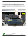
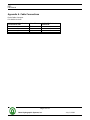
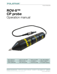
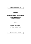
1
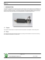
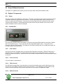
Digibar V
USER MANUAL
Version: 0.1
Odom Hydrographic Systems, Inc.
1450 Seaboard Avenue
Baton Rouge, Louisiana
USA
70810-6261
Telephone: (225) 769-3051
Fax: (225) 766-5122
[email protected]
http://www.odomhydrographic.com
Number of pages: 165
Date: July 21, 2008
ES3
User Manual
Revision History
Version
0.1
Date
07-21-2008
07-22-2008
Author
S. Apsey
R. Byrd
Remarks
Initial version – draft
Draft description of mounting options
© ODOM HYDROGRAPHIC SYSTEMS, INC. 2008
All rights are reserved. Reproduction in whole or in part is prohibited without the prior written consent of the copyright owner.
The information presented in this document does not form part of any quotation or contract, is believed to be
accurate and reliable and may be subject to change without notice. The publisher will not accept any liability for
any consequence of its use. Publication thereof does not convey nor imply any license under patent- or other
industrial or intellectual property rights.
Page 2 of 16
Odom Hydrographic Systems, Inc.
July 21, 2008
ES3
User Manual
CONTENTS
1
Introduction...................................................................................................................................................... 4
1.1
1.2
2
Purpose ....................................................................................................................................................... 4
Scope .......................................................................................................................................................... 4
Product description......................................................................................................................................... 5
2.1
Digibar V General Specifications ................................................................................................................ 5
2.2
PROBE........................................................................................................................................................ 5
2.3
DBV J-Box................................................................................................................................................... 5
2.4
Scope Of Material Included......................................................................................................................... 6
2.5
Digibar V Components ................................................................................................................................ 6
2.5.1
Probe.................................................................................................................................................... 6
2.5.2
Junction Box ........................................................................................................................................ 6
2.5.2.1
Power Switch ................................................................................................................................ 6
2.5.2.2
Probe Connector........................................................................................................................... 6
2.5.2.3
USB Connector............................................................................................................................. 6
2.5.2.4
RS232 Connector ......................................................................................................................... 6
2.5.3
Cables .................................................................................................................................................. 7
3
Installation........................................................................................................................................................ 8
3.1
USB Driver Installation ................................................................................................................................ 8
3.2
Communication Testing .............................................................................................................................. 9
3.3
Configuring the Digibar V Output String.................................................................................................... 11
3.3.1
Units of Operation .............................................................................................................................. 11
3.3.2
Data Output Rate ............................................................................................................................... 11
3.3.3
Data Output String ............................................................................................................................. 11
3.4
Probe Installation ...................................................................................................................................... 12
4
TroublEshooting............................................................................................................................................ 14
Appendix A. Cable Connections .......................................................................................................................... 15
Appendix B. Output Strings ................................................................................................................................. 16
Page 3 of 16
Odom Hydrographic Systems, Inc.
July 21, 2008
ES3
User Manual
1 INTRODUCTION
The Digibar V was designed to continuously measure sound velocity near the transducer array of Multibeam echo
sounders. The Digibar V uses a 2 MHz transducer and time of flight circuitry sounding across a know distance to
measure the sound velocity directly. The housing of the Digibar V was designed to allow for flexible attachment
options in order to place the velocimeter near the Multibeam echo sounder’s transducer array.
1.1
Purpose
The purpose of this document is to explain the features and operation of the Digibar V sound velocity probe.
1.2
Scope
The scope and content of this document is focused on providing useful information to the end-user concerning
both installation and operation of the instrument.
Page 4 of 16
Odom Hydrographic Systems, Inc.
July 21, 2008
ES3
User Manual
2 PRODUCT DESCRIPTION
2.1
Digibar V General Specifications
2.2
PROBE
Body Dimensions:
•
22.5 cm in length
•
4.5 cm square
Sounding Chamber:
•
Path Length – 63.5 mm
•
Head Material – 316 Stainless
•
Spacers – 316 Stainless
•
Reflector Plate – 316 Stainless
•
Acoustic Frequency – 2MHz
Communications:
•
RS232, 19.2 k Baud
Temperature Range (operation)
•
1°C to 45°C (typical, other ranges available)
Velocity Range:
•
1400 – 1600 m/sec
Sample Rate:
•
> 100 Hz
Output Rate:
•
Selectable up to 10 Hz
Resolution:
•
0.1m/sec
Accuracy:
•
±0.2m/sec
Submersion Depth:
•
50 m max.
2.3
DBV J-Box
Communications:
•
RS232 19.2 k Baud (2 ports)
•
USB (1 port)
Power:
•
USB 5 VDC, <5 Watts
Page 5 of 16
Odom Hydrographic Systems, Inc.
July 21, 2008
ES3
User Manual
2.4
Scope Of Material Included
The Digibar V is supplied with the probe, junction box, probe cable, USB cable and RS232 cable.
2.5
Digibar V Components
2.5.1
Probe
The main component of the Digibar V is the probe. The probe is connected to the junction box with the supplied
underwater connector through the Seacon connector. The connector should have a silicon lubricant on it to
ensure it connects and seals properly. The probe uses a time-of-flight technique to determine sound velocity
using the 2 MHz transducer. Care should always be taken with the acoustic chamber of the probe as it will
require recalibration should it become dislodged.
2.5.2
Junction Box
The junction box supplies power to the Digibar V probe and converts the RS232 data from the probe to USB so
that it can interface to the pc. The junction box can also supply RS232 data to the pc. The junction box is
powered up with the USB connector. If the USB port is not used to interface with a pc a USB power supply can
be used to power up the junction box.
2.5.2.1
Power Switch
Once the junction box is plugged into a pc the power switch will power up the probe. While the junction box is
plugged into the pc the junction box is always powered up to keep its port enumerated on the pc. The power
switch only powers up the probe. There is an LED in the middle of the power switch to indicate whether the probe
is turned on.
2.5.2.2
Probe Connector
The probe cable is connected here.
2.5.2.3
USB Connector
The USB cable is plugged here to provide power to the junction box/probe and to transfer USB data to the pc.
This port is the only means of powering up the junction box/probe. If the USB port is not being used for data
transfer it can be connected to a pc to power up the probe or connected to AC/USB power supply.
2.5.2.4
RS232 Connector
Page 6 of 16
Odom Hydrographic Systems, Inc.
July 21, 2008
ES3
User Manual
The RS232 connector is used to transfer data from the probe should the USB port not be used. Both ports can be
used simultaneously. Data is transmitted at 19,200, N, 8, 1.
2.5.3
Cables
The Digibar V is supplied with a serial cable, USB cable and probe cable.
Page 7 of 16
Odom Hydrographic Systems, Inc.
July 21, 2008
ES3
User Manual
3 INSTALLATION
This section contains information necessary to install the USB drivers and install the Digibar V probe.
3.1
USB Driver Installation
The USB port of the Digibar V junction box uses a virtual serial port driver to send and receive data to the
computer. Once the USB drivers are installed, the application that is going to use the Digibar V will treat the port
like a normal serial port.
1. Install the software BEFORE plugging the Digibar V to the computer.
2. Insert the USB driver disk that is included with the Digibar V in the computer. If the disk is not available,
download the program from our web site.
3. Run the CP210xVCPInstaller.exe file.
4. Once the program has installed plug in the Digibar V junction box to the computer using the included USB
cable. Plug in the Digibar V probe to the junction box using the probe cable
5. Go to Device Manager on the computer and expand the Ports (COM & LPT) section. The USB drivers
will enumerate the Digibar V to the next available com port. The com port will be labelled “CP210x USB
to UART Bridge Controller (COM X)” where X is the com port number that the application should use to
communicate with the Digibar V. In the example below the Digibar V has enumerated to COM18.
Page 8 of 16
Odom Hydrographic Systems, Inc.
July 21, 2008
ES3
User Manual
3.2
Communication Testing
To test the Digibar V use the TTY.exe program that is included on the CD with the USB drivers. The TTY.exe
program can also be downloaded from the Support->Utilities portion of our web site.
Make sure the Digibar V is connected to the junction box and the junction box is connected to the computer.
Power up the Digibar V. The LED on the power switch should turn red. To test the Digibar V, it is permissible to
have the probe out of the water.
Start the TTY program. Go to Settings…. Set the Port to the COM port indicated in Device Manager. Set the
Baud Rate to 19.2k. Make sure RTS/CTS is unchecked and New Line is unchecked. Click Ok.
Page 9 of 16
Odom Hydrographic Systems, Inc.
July 21, 2008
ES3
User Manual
Go to Action->Connect and data should start scrolling down the screen.
Page 10 of 16
Odom Hydrographic Systems, Inc.
July 21, 2008
ES3
User Manual
3.3
Configuring the Digibar V Output String
The are a number of parameters that can be changed on the Digibar V. These include the:
Units of Operation
Data Output Rate
Data Output String
All changes to the configuration of the Digibar V are made through either the RS232 I/O port or the USB port.
The TTY program included with the installation disk or any other terminal program can be used. Refer to section
3.2 on how to set up the TTY program. Once data is scrolling up the screen in TTY use the following commands
to change the parameters.
3.3.1
Units of Operation
Using the keyboard on the computer type in:
@t<SP>(M or F)<ENTER>
SP = space key
ENTER = Enter key
Use:
M for Meters/sec
F for Feet/sec
3.3.2
Data Output Rate
Using the keyboard on the computer type in:
@j<SP>(0.1 to 9.9)
SP = space key
ENTER = Enter key
Notes:
0.1 sets the output rate to 0.1 times/second (very slow)
9.9 sets the output rate to 9.9 times/second (fastest)
Any value between 0.1 and 9.9 can be used but must be two digits. So for 1 time/second use 1.0 as the value to
enter.
3.3.3
Data Output String
@f
Selects the Odom string (velocity only)
@e
Selects to NMEA string
Page 11 of 16
Odom Hydrographic Systems, Inc.
July 21, 2008
ES3
User Manual
3.4
Probe Installation
The Digibar V is designed so that the sampling chamber is oriented 90 degrees with respect to the long axis of
the probe body. Ideal mounting would position the probe so that the rounded nose of the probe and the wide
opening of the sampling chamber face into the flow of water. This orientation aids the smooth flow of water
through the chamber and even allows accurate sound velocity measurements with a flow velocity in excess of 10
knots.
The probe transducer housing provides six thread holes (two holes on each of three sides) to accommodate M4
screws for attaching the unit to a flat plate. In addition, the body can be mounted to a “non-flat” surface using the
two “notched” areas in the body. One notch is near the transducer housing and the second near the power/data
connector. Heavy duty Ty-Wraps or hose clamps can be used to bind the probe to an irregular surface and to
provide additional support down the length of the probe body to both stabilize the unit and to protect the
Power/Signal cable from strumming.
The objective of choosing the mount position is to see that the probe samples the same or very nearly the same
water that the beam steering multibeam transducer array encounters.
Threaded
Mounting Holes
Notches
Digibar V Simplified
Diagram
Page 12 of 16
Odom Hydrographic Systems, Inc.
July 21, 2008
ES3
User Manual
The picture below shows the Digibar V installed on a flat plate adjacent to an ES3 multibeam (in its optional
streamlined fairing), which in turn is mounted on a Stainless Steel pipe over the side of a small survey boat. The
unit is secured to the plate by two M4 screws and the power/signal cable is strapped to the body by the three Tywraps. The cable must be protected in order to avoid the vibration/strumming caused by the flow of water over
the assembly.
Water Flow
Ty-wraps securing the
underwater cable to
the probe body.
Mounting
Screw
Digibar V and ES3
Over the side
Page 13 of 16
Odom Hydrographic Systems, Inc.
July 21, 2008
ES3
User Manual
4 TROUBLESHOOTING
•
The Digibar V should be calibrated on an annual basis to make sure that is stays within specifications.
•
The surface of the Digibar V must always be clean and free of oils. If the Digibar V is not outputting
correct sound velocities then clean the face of the transducer with some liquid detergent.
•
A quick test of whether the Digibar V is working properly is to put the probe in a bucket of fresh water and
let it sit there for five minutes. Measure the temperature of the water and compare the sound velocity in
the chart below at the temperature measured with the sound velocity the Digibar V is outputting.
Temperature
4.00
4.50
5.00
5.50
6.00
6.50
7.00
7.50
8.00
8.50
9.00
9.50
10.00
10.50
11.00
11.50
12.00
12.50
13.00
13.50
14.00
14.50
15.00
15.50
16.00
16.50
17.00
Sound Velocity
1421.62
1423.90
1426.15
1428.38
1430.58
1432.75
1434.90
1437.02
1439.12
1441.19
1443.23
1445.25
1447.25
1449.22
1451.17
1453.09
1454.99
1456.87
1458.72
1460.55
1462.36
1464.14
1465.91
1467.65
1469.36
1471.06
1472.73
Temperature
17.50
18.00
18.50
19.00
19.50
20.00
20.50
21.00
21.50
22.00
22.50
23.00
23.50
24.00
24.50
25.00
25.50
26.00
26.50
27.00
27.50
28.00
28.50
29.00
29.50
30.00
Sound Velocity
1474.38
1476.01
1477.62
1479.21
1480.77
1482.32
1483.84
1485.35
1486.83
1488.29
1489.74
1491.16
1492.56
1493.95
1495.32
1496.66
1497.99
1499.30
1500.59
1501.86
1503.11
1504.35
1505.56
1506.76
1507.94
1509.10
Page 14 of 16
Odom Hydrographic Systems, Inc.
July 21, 2008
ES3
User Manual
Appendix A. Cable Connections
Probe Cable Connector
P/N JMS3116J10-6P
JMS3116J10-6P Pin Number
Junction Box Side
A
B
C
D
Color Wire
Red
Green
White
Black
MCBH-5FS Pin Number
Probe Side
1
2
3
4
Page 15 of 16
Odom Hydrographic Systems, Inc.
July 21, 2008
ES3
User Manual
Appendix B. Output Strings
Odom Velocity Only String (AML)
<space>1477.40<CR><LF> in Meters/Sec
<space>4847.40<CR><LF> in Meters/Sec
NMEA String
$PSSV,1499.2,.0,<checksum>
All data is ASCII 19200,N,8,1.
Page 16 of 16
Odom Hydrographic Systems, Inc.
July 21, 2008