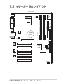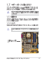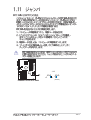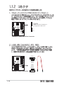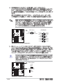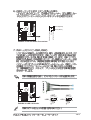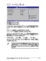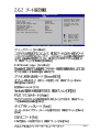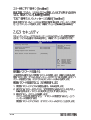
1
P4G800-V
Motherboard
®
Checklist
ii
iii
Features
Safeguards
iv
Federal Communications Commission Statement
This device complies with FCC Rules Part 15. Operation is subject to the
following two conditions:
•
•
This device may not cause harmful interference, and
This device must accept any interference received including interference
that may cause undesired operation.
This equipment has been tested and found to comply with the limits for a
Class B digital device, pursuant to Part 15 of the FCC Rules. These limits
are designed to provide reasonable protection against harmful interference
in a residential installation. This equipment generates, uses and can radiate
radio frequency energy and, if not installed and used in accordance with
manufacturer’s instructions, may cause harmful interference to radio
communications. However, there is no guarantee that interference will not
occur in a particular installation. If this equipment does cause harmful
interference to radio or television reception, which can be determined by
turning the equipment off and on, the user is encouraged to try to correct the
interference by one or more of the following measures:
• Reorient or relocate the receiving antenna.
• Increase the separation between the equipment and receiver.
• Connect the equipment to an outlet on a circuit different from that to
which the receiver is connected.
• Consult the dealer or an experienced radio/TV technician for help.
The use of shielded cables for connection of the monitor to the
graphics card is required to assure compliance with FCC regulations.
Changes or modifications to this unit not expressly approved by the
party responsible for compliance could void the user’s authority to
operate this equipment.
Canadian Department of Communications Statement
This digital apparatus does not exceed the Class B limits for radio noise
emissions from digital apparatus set out in the Radio Interference
Regulations of the Canadian Department of Communications.
This class B digital apparatus complies with Canadian ICES-003.
v
vi
vii
viii
®
®
®
®
ix
x
®
®
®
®
®
®
1-2
®
®
®
1-3
1
2 3
4
5
6
7
15
14
8
13
12
11
16
10 9
18
17
19
20
21
26
1-4
25
24
23
22
1
2
®
3
®
®
®
4
5
6
7
8
9
10
11
12
13
14
1-5
15
16
17
18
19
20
21
22
23
24
25
26
1-6
24.5cm (9.6in)
PS/2
0 1 2 3
CHA_FAN1
PCI 1
PCI 2
Audio
Codec
PCI 3
AUX IN
PCI 4
BUZZ1
BATTERY1
Realtek
RTL8101L
FLOPPY1
4 5 6 7
Accelerated Graphics Port
Intel
P31
ICH5
P30
4Mb
BIOS
30.5cm (12.0in)
Top:Line In
Center:Line Out
Below:Mic In
SECONDARY IDE
865G
GMCH
PRIMARY IDE
Intel
ATX12V1
ATX Power Connector
Top:
USB3 RJ-45
USB4
DDR DIMM4 (64-bit, 184-pin module)
Bottom:
P4G800-V
USB12
DDR DIMM3 (64-bit, 184-pin module)
VGA
DDR DIMM2 (64-bit, 184-pin module)
PARALLEL PORT
CPU_FAN1
DDR DIMM1 (64-bit, 184-pin module)
Socket 478
COM1
Super
I/O
T: Mouse
B: Keyboard
J19
CD IN
USB2
USB1
PCI 5
PCI 6
HPANEL1
1-7
1-8
1-9
®
®
®
1-10
®
90 - 100
1-11
P4G800-V
104 Pins
1-12
DIMM4
DIMM3
DIMM2
P4G800-V 184-Pin DDR
DIMM Sockets
DIMM1
80 Pins
800 MHz
PC3200/PC2700*/PC2100
400/333*/266 MHz
533 MHz
PC2700/PC2100
333/266 MHz
400 MHz
PC2100
266 MHz
1-13
256MB
256MB
256MB
512MB
128MB
256MB
128MB
1-14
Apacer
SAMSUNG
Winbond
ATP
NANYA
TwinMos
Infineon
77.10636.465
M368L3223ETM-CCC
W9425GCDB-5
AG32L64T8SQC4S
NT128D64SH4b1G-5T
M2G9I08AFATT9F081AA4T
HYS64D16301GU-5-B
SAMSUNG
SAMSUNG
Winbond
SAMSUNG
NANYA
TwinMos
Infineon
SS K4H560838D-TCC4
SS K4H560838E-TCCC
SS W942508CH-5
DS K4H560838D-TCC4
SS NT5DS16M16BT-5T
SS TMD7608F8E50D
SS HYB25D256160BT-5B
A
PCI
PCI
PCI
PCI
PCI
PCI
AGP
B
C
D
E
F
G
H
1
2
3
4
5
6
USB
USB
USB
USB
USB 2.0
LAN
HC0
HC1
HC2
HC3
PCI
ì
2
IRQî
IRQ
PCI
1-15
P4G800-V
P4G800-V Accelerated Graphics Port (AGP)
1-16
P4G800-V
J19
1 2 3
1 2 3
Clear CMOS
Normal
(Default)
P4G800-V Clear RTC RAM
1-17
FLOPPY
P4G800-V
NOTE: Orient the red markings on
the floppy ribbon cable to PIN 1
PIN 1
P4G800-V Floppy Disk Drive Connector
GND
RSATA_RXP2
RSATA_RXN2
GND
RSATA_TXN2
RSATA_TXP2
GND
P4G800-V
P31
GND
RSATA_RXN2
RSATA_RXP2
GND
RSATA_TXN2
RSATA_TXP2
GND
P30
P4G800-V SATA Connectors
1-18
SECONDARY IDE
PIN 1
P4G800-V IDE Connectors
PRIMARY IDE
P4G800-V
NOTE: Orient the red markings
(usually zigzag) on the IDE
ribbon cable to PIN 1.
PIN 1
1-19
P4G800-V
ATX12V1
GND
+12V DC
GND
+12V DC
P4G800-V ATX Power Connector
P4G800-V
GND
+12V
Rotation
CPU_FAN1
CHA_FAN1
GND
+12V
Rotation
P4G800-V 12-Volt Cooling Fan Power
1-20
ATXPWR1
+12.0VDC
+5VSB
PWR_OK
COM
+5.0VDC
COM
+5.0VDC
COM
+3.3VDC
+3.3VDC
+5.0VDC
+5.0VDC
-5.0VDC
COM
COM
COM
PS_ON#
COM
-12.0VDC
+3.3VDC
1
5
6
10
USB1
USB+5V
LDM2
LDP2
GND
USB2
USB+5V
LDM4
LDP4
GND
P4G800-V USB 2.0 Header
USB+5V
LDM1
LDP1
GND
NC
USB+5V
LDM3
LDP3
GND
NC
P4G800-V
Left Audio Channel
Ground
Right Audio Channel
P4G800-V
AUX IN(White)
CD IN (Black)
P4G800-V Internal Audio Connectors
1
5
6
10
1-21
ATX Power
Switch*
P4G800-V
PLED+
PLEDPWR
GND
Power LED
HDLED+
HDLEDGround
Reset
HPANEL1
HDLED
P4G800-V Front Panel Audio Connector
1-22
Reset SW
2-2
i
A:\>afudos /ip4g800v.rom
AMI Firmware Update Utility - Version 1.10
Copyright (C) 2002 American Megatrends, Inc. All rights reserved.
Reading file ..... done
Erasing flash .... done
Writing flash .... 0x0008CC00 (9%)
A:\>afudos /ip4g800v.rom
AMI Firmware Update Utility - Version 1.10
Copyright (C) 2002 American Megatrends, Inc. All rights reserved.
Reading file ..... done
Erasing flash .... done
Writing flash .... 0x0008CC00 (9%)
Verifying flash .. done
A:\>
2-3
User recovery requested. Starting BIOS recovery...
Checking for floppy...
User recovery requested. Starting BIOS recovery...
Checking for floppy...
Floppy found!
Reading file “p4g800v.rom”. Completed.
Start flashing...
Flashed successfully. Rebooting.
2-4
2-5
System Time
System Date
Legacy Diskette A
Primary IDE Master
Primary IDE Slave
Secondary IDE Master
Secondary IDE Slave
Third IDE Master
Fourth IDE Master
IDE Configuration
System Information
2-6
[11:10:19]
[Thu 05/27/2003]
[1.44M, 3.5 in]
:[ST320413A]
:[ASUS CD-S340]
:[Not Detected]
:[Not Detected]
:[Not Detected]
:[Not Detected]
Use [ENTER], [TAB]
or [SHIFT-TAB] to
select a field.
Use [+] or [-] to
configure system time.
+Tab
F1
F10
ESC
Select Screen
Select Item
Change Field
Select Field
General Help
Save and Exit
Exit
System Time
System Date
Legacy Diskette A
Primary IDE Master
Primary IDE Slave
Secondary IDE Master
Secondary IDE Slave
Third IDE Master
Fourth IDE Master
IDE Configuration
[11:10:19]
[Thu 05/27/2003]
[1.44M, 3.5 in]
:[ST320413A]
:[ASUS CD-S340]
:[Not Detected]
:[Not Detected]
:[Not Detected]
:[Not Detected]
System Information
Use [ENTER], [TAB]
or [SHIFT-TAB] to
select a field.
Use [+] or [-] to
configure system time.
+Tab
F1
F10
ESC
Advanced PCI/PnP settings
WARNING: Setting wrong values in the sections below
may cause system to malfunction.
Plug and Play OS
PCI Latency Timer
Allocate IRQ to PCI VGA
Palette Snooping
PCI IDE BusMaster
[No]
[64]
[Yes]
[Disabled]
[Enabled]
IRQ3
IRQ4
IRQ5
IRQ7
IRQ9
IRQ10
IRQ11
[Available]
[Available]
[Available]
[Available]
[Available]
[Available]
[Available]
Select Screen
Select Item
Change Field
Select Field
General Help
Save and Exit
Exit
NO: Lets the bIOS
configure all the
devices in the system.
YES: Lets the
operating system
configure Plug and
Play (PnP) devices not
required for boot if
your system has a Plug
and Play operating
system.
+F1
F10
ESC
Select Screen
Select Item
Change Option
General Help
Save and Exit
Exit
2-7
System Time
System Date
Legacy Diskette A
Primary IDE Master
Primary IDE Slave
Secondary IDE Master
Secondary IDE Slave
Third IDE Master
Fourth IDE Master
IDE Configuration
System Information
2-8
[11:10:19]
[Thu 05/27/2003]
[1.44M, 3.5 in]
:[ST320413A]
:[ASUS CD-S340]
:[Not Detected]
:[Not Detected]
:[Not Detected]
:[Not Detected]
Use [ENTER], [TAB]
or [SHIFT-TAB] to
select a field.
Use [+] or [-] to
configure system time.
+Tab
F1
F10
ESC
Select Screen
Select Item
Change Field
Select Field
General Help
Save and Exit
Exit
Primary IDE Master
Select the type
of device connected
to the system.
Device
: Hard Disk
Vendor
: ST320413A
Size
: 20.0GB
LBA Mode
: Supported
Block Mode
: 16 Sectors
PIO Mode
: 4
Async DMA
: MultiWord DMA-2
Ultra DMA
: Ultra DMA-5
SMART Monitoring: Supported
Type
LBA/Large Mode
Block (Multi-sector Transfer)
PIO Mode
DMA Mode
Smart Monitoring
32Bit Data Transfer
[Auto]
[Auto]
[Auto]
[Auto]
[Auto]
[Auto]
[Disabled]
+F1
F10
ESC
Select Screen
Select Item
Change Option
General Help
Save and Exit
Exit
2-9
IDE Configuration
Onboard IDE Operate Mode
Enhanced Mode Support On
IDE Detect Time Out (Sec)
[Enhanced Mode]
[S-ATA]
[35]
+F1
F10
ESC
2-10
Select Screen
Select Item
Change Option
General Help
Save and Exit
Exit
2-11
AMI BIOS
Version
: 08.00.09
Build Date : 05/27/03
Processor
Type
Speed
Count
: Intel(R) Pentium(R) 4 CPU 2.53GHz
: 2530 MHz
: 1
System Memory
Size
: 256MB
+F1
F10
ESC
2-12
Select Screen
Select Item
Change Option
General Help
Save and Exit
Exit
CPU Configuration
Chipset
Onboard Devices Configuration
PCI PnP
USB Configuration
Configure CPU.
Select Screen
Select Item
Enter Go to Sub-screen
F1
General Help
F10
Save and Exit
ESC
Exit
Configure advanced CPU settings
Manufacturer
Brand String
Frequency
: Intel(R)
: Intel(R) Pentium(R) 4 CPU 2.53GHz
: 2530 MHz
Ratio Status : Locked
Ratio Actual Value : 18
Hyper Threading Technology
[Enabled]
+F1
F10
ESC
Select Screen
Select Item
Change Option
General Help
Save and Exit
Exit
2-13
Advanced Chipset settings
WARNING: Setting wrong values in the sections below
may cause system to malfunction.
2-14
Configure DRAM Timing by SPD
[Enabled]
Graphic Adapter Priority
Onboard Video Memory
Graphics Aperture Size
Spread Spectrum
[AGP/Int. VGA]
[Enabled, 8MB]
[ 64 MB]
[Enabled]
Boot Display Device
Flat Panel Type
TV Standard
[Auto]
[640x480 LVDS]
[Auto]
MPS Revision
[1.4]
Set the CPU external
frequency for next
boot.
+F1
F10
ESC
Select Screen
Select Item
Change Option
General Help
Save and Exit
Exit
2-15
OnBoard Audio
OnBoard LAN
OnBoard LAN Boot ROM
[Auto]
[Enabled]
[Disabled]
Serial Port1 Address
Parallel Port Address
Parallel Port Mode
ECP Mode DMA Channel
Parallel Port IRQ
[3F8/IRQ4]
[378]
[ECP]
[DMA3]
[IRQ7]
+F1
F10
ESC
2-16
Select Screen
Select Item
Change Option
General Help
Save and Exit
Exit
2-17
Advanced PCI/PnP settings
WARNING: Setting wrong values in the sections below
may cause system to malfunction.
Plug and Play OS
PCI Latency Timer
Allocate IRQ to PCI VGA
Palette Snooping
PCI IDE BusMaster
[No]
[64]
[Yes]
[Disabled]
[Enabled]
IRQ3
IRQ4
IRQ5
IRQ7
IRQ9
IRQ10
IRQ11
[Available]
[Available]
[Available]
[Available]
[Available]
[Available]
[Available]
IRQ11
IRQ14
IRQ15
[Available]
[Available]
[Available]
DMA
DMA
DMA
DMA
DMA
DMA
Channel
Channel
Channel
Channel
Channel
Channel
0
1
3
5
6
7
Reserved Memory Size
2-18
[Available]
[Available]
[Available]
[Available]
[Available]
[Available]
[Disabled]
NO: Lets the bIOS
configure all the
devices in the system.
YES: Lets the
operating system
configure Plug and
Play (PnP) devices not
required for boot if
your system has a Plug
and Play operating
system.
+F1
F10
ESC
Select Screen
Select Item
Change Option
General Help
Save and Exit
Exit
+F1
F10
ESC
Select Screen
Select Item
Change Option
General Help
Save and Exit
Exit
2-19
USB Configuration
Module Version
Enables USB host
controllers.
: 2.22.4-5.3
USB Devices Enabled : None
USB Function
Legacy USB Support
USB 2.0 Controller
USB 2.0 Controller Mode
[8 USB Ports]
[Auto]
[Enabled]
[HiSpeed]
USB Mass Storage Device Configuration
+F1
F10
ESC
2-20
Select Screen
Select Item
Change Option
General Help
Save and Exit
Exit
USB Mass Storage Device Configuration
USB Mass Storage Reset Delay
[20 Sec]
No USB Mass Storage device detected
Device #1
Emulation
Device #2
Emulation
Device #3
Emulation
Device #4
Emulation
Device #5
Emulation
Device #6
Emulation
Type
Type
Type
Type
Type
Type
N/A
[N/A]
N/A
[N/A]
N/A
[N/A]
N/A
[N/A]
N/A
[N/A]
N/A
[N/A]
Number of seconds
POST waits for the USB
mass storage device
after that start unit
command.
+F1
F10
ESC
Select Screen
Select Item
Change Option
General Help
Save and Exit
Exit
2-21
Suspend Mode
Repost Video on S3 Resume
ACPI 2.0 Support
ACPI APIC Support
BIOS -> AML ACPI table
[Auto]
[No]
[No]
[Enabled]
[Enabled]
Configure CPU.
APM Configuration
Hardware Monitor
Select Screen
Select Item
Enter Go to Sub-screen
F1
General Help
F10
Save and Exit
ESC
Exit
2-22
APM Configuration
Power Management/APM
Video Power Down Mode
Hard Disk Power Down Mode
Suspend Time Out
Throttle Slow Clock Ratio
[Enabled]
[Suspend]
[Suspend]
[Disabled]
[50%]
System Thermal
[Disabled]
Power Button Mode
Restore on AC Power Loss
[On/Off]
[Power Off]
Resume on RTC Alarm
Resume on Ring
Resume on PME#
[Disabled]
[Disabled]
[Disabled]
Enabled or disable
APM.
+F1
F10
ESC
Select Screen
Select Item
Change Option
General Help
Save and Exit
Exit
2-23
2-24
Hardware Monitor
CPU temperature
CPU Temperature
MB Temperature
[44°C/111°F]
[36°C/96.5°F]
CPU Fan Speed
Chassis Fan Speed
[2250RPM]
[XXX RPM]
VCORE Voltage
3.3V Voltage
5V Voltage
12V Voltage
[1.550V]
[3.386V]
[4.890V]
[11.900V]
+F1
F10
ESC
Select Screen
Select Item
Change Option
General Help
Save and Exit
Exit
2-25
Boot Settings
Specifies the Boot
Device Priority
sequence.
Boot Device Priority
Boot Settings Configuration
Security
Select Screen
Select Item
Enter Go to Sub-screen
F1
General Help
F10
Save and Exit
ESC
Exit
Boot Device Priority
1st Boot Device
2nd Boot Device
3rd Boot Device
[First Floppy Drive]
[PM-ST320413A]
[PS-ASUS CD-S340]
Specifies the boot
sequence from the
available devices.
A device enclosed in
parenthesis has been
disabled in the
corresponding type
menu.
+F1
F10
ESC
2-26
Select Screen
Select Item
Change Option
General Help
Save and Exit
Exit
Boot Settings Configuration
Quick Boot
Full Screen Logo
Add On ROM Display Mode
Bootup Num-Lock
PS/2 Mouse Support
Typematic Rate
Boot to OS/2
Wait for ‘F1’ If Error
Hit ‘DEL’ Message Display
[Enabled]
[Enabled]
[Force BIOS]
[On]
[Auto]
[Fast]
[No]
[Enabled]
[Enabled]
Allows BIOS to skip
certain tests while
booting. This will
decrease the time
needed to boot the
system.
+F1
F10
ESC
Select Screen
Select Item
Change Option
General Help
Save and Exit
Exit
2-27
Security Settings
Supervisor Password
User Password
Not Installed
Not Installed
<Enter> to change
password.
<Enter> again to
disable password.
Change Supervisor Password
Boot Sector Virus Protection
[Disabled]
+F1
F10
ESC
2-28
Select Screen
Select Item
Change Option
General Help
Save and Exit
Exit
Security Settings
Supervisor Password
User Password
Change Supervisor Password
User Access Level
Change User Password
Clear User Password
Password Check
Boot Sector Virus Protection
Installed
Not Installed
<Enter> to change
password.
<Enter> again to
disable password.
[Full Access]
[Setup]
[Disabled]
+F1
F10
ESC
Select Screen
Select Item
Change Option
General Help
Save and Exit
Exit
2-29
2-30
Exit Options
Exit & Save Changes
Exit & Discard Changes
Discard Changes
Load Setup Defaults
Exit system setup
after saving the
changes.
F10 key can be used
for this operation.
Select Screen
Select Item
Enter Go to Sub-screen
F1
General Help
F10
Save and Exit
ESC
Exit
2-31
2-32
3-2
®
®
3-3
3-4