1
VH1000
C 2007 Thermaltake Technology Co., Ltd. All Rights Reserved. 2007.06
All other registered trademarks belong to their respective companies. www.thermaltake.com
Tested To Comply
With FCC Standards
FOR HOME OR OFFICE USE
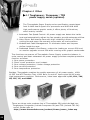
VH1000BWS
VH1000
Chapter 1. Product Introduction
1.1 Specification
1
Chapter 2. Case Mechanical Operation
2.1
2.2
2.3
2.4
2.5
2.6
2.7
2.8
2.9
2.10
2.11
2.12
2.13
How to open the side panel
Lock operation
Installing 5.25" device
Installing 3.5" HDD
Front removable fan cage
Installing 3.5" HDD (front fan cage)
5.25" to 3.5" drive tray device installation
Installing Hard Drive to Device Tray
Installing Floppy Disk Drive to Device Tray
Installing 3.5" device to drive tray with power button
Installing power supply
Installing the fan on top of the case
How to remove the fan & fan holder
Air cooling system
PCI slot tool-free usage
2
2
3
4
5
7
8
8
9
11
12
13
13
14
15
Chapter 3. Motherboard & Leads Installation
3.1
3.2
3.3
3.4
3.5
3.6
3.7
Before installing motherboard
Motherboard installation
Case LED connection
USB 2.0 connection
Audio connection
eSATA connection
Intrusion open alarm function
16
17
18
19
20
21
21
Chapter 4. Other
4.1 Toughpower / Purepower / TR2
power supply series (optional)
22
Chapter 1. Product Introduction
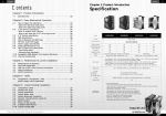
1.1 Specification
Model
VH1000BWS
Case Type
Full Tower
Side Panel
Transparent window
Dimension
(H*W*D)
540.0 x 220.0 x 580.0 mm
(21.3 x 8.7 x 22.8 inch)
Front (Intake) :
120 x 120 x 25 mm, 1300rpm, 17dBA
Rear (Exhaust) :
Cooling System
120 x 120 x 25 mm blue LED fan, 1300rpm, 17dBA;
90 x 90 x 25 mm, 1800rpm, 19dBA
Top (Exhaust) :
90 x 90 x 25mm, 1800rpm, 19dBA
Drive Bays
Front Accessible
Internal
Material
11
Up tp 10 x 5.25", 2 x 3.5"
6 x 3.5"
Chassis : 1.0mm SECC
Front door : Aluminum
Black
Color
7
Expansion Slots
Motherboards
PSU
I/O Ports
Micro ATX , ATX, Extend ATX
Standard ATX PSII (Option)
USB 2.0 x 2, e-SATA connector x 1, HD Audio
- Piano black finish
- Brushed aluminum front door
- e-SATA connector built-in
Features
- Support up to eleven 5.25" drive bays
- Ventilation openings on top (62% opening ratio)
- High efficiency ventilation : 120mm silent fans
at front and rear, 90mm fans on top and rear
- Removable HDD cage
1
VH1000
Chapter 2 Case Mechanical Operation
2.1 How to open the side panel
1
To remove the side panel,
please remove upper and
bottom thumb screws on
the back of the case.
2
Please find out the side
panel key in the back of
the chassis, then open
the side panel as shown.
3
Push the button then
swing out the side
panel.
2.2 Lock operation
1
2
3
Insert the provided key and turn it counterclockwise to open the front door.
2
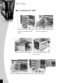
2.3 Installing 5.25" device
1
2
1
2
Squeeze and pull outward
the tool-free clip.
Remove the drive bay cover
from the selected location.
Then insert the device into
the 5.25" drive bay.
3
1
2
4
Squeeze and push inward
the tool-free clip.
5
Finish installation.
3
VH1000
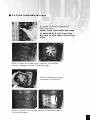
2.4 Installing 3.5" HDD
1
2
Unscrew the thumb screw Push the handle down and
of the removable HDD
pull the cage out.
cage.
3
Silde HDD into the cage.
4
Screw up and fasten HDD
by screws.
5
Slide the cage back and screw up the thumb screw.
4
2.5 Front removable fan cage
1
2
1
Squeeze and pull outward the
tool-free clip.
Note: Front removable fan cage
is secured by 3 tool-free clips.
Be sure to free these 3 tool-free
clips.
2
After loosen tool-free clips, remove 3 drive bay
covers located in front of the fan cage.
Then slide the fan cage
outward to remove it.
3
4
Remove other 3 drive bay covers at desired location
for the fan cage.
5
VH1000
Squeeze and pull outward
the tool-free clips at
desired location.
1
2
5
6
Slide the fan cage back to the drive bays.
1
Squeeze and push inward
the tool-free clips to
secure the fan cage.
2
7
8
Place back the drive bay covers removed earlier.
6
2.6 Installing 3.5" HDD (front fan cage)
1
2
1
Squeeze and pull outward
the tool-free clips of the
front HDD cage.
2
Remove the drive bay
covers and slide the fan
cage outward to remove it.
3
Slide HDD into the cage.
4
Screw up and fasten HDD
by screws.
5
Slide the cage back to drive bays.
6
Squeeze and push inward
the tool-free clips to
secure the fan cage.
7
VH1000
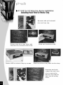
2.7 5.25" to 3.5" drive tray device installation
Installing Hard Drive to Device Tray
Squeeze and pull outward
the tool-free clip.
1
2
1
3
2
Remove the drive bay cover and
unscrew the screws at both side.
Slide out the device tray.
5
4
Fasten HDD on device tray by screws.
Slide the device tray back to drive bay.
Squeeze and push
inward the tool-free
clip to secure the
device tray and put
back the drive bay
cover.
1
2
6
8
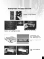
Installing Floppy Disk Drive to Device Tray
Squeeze and pull outward
the tool-free clip.
1
2
1
3
2
Remove the drive bay cover and
unscrew the screws at both side.
Slide out the device tray.
Insert floppy disk
drive into the device
tray. Secure FDD with
screws from both side
of device tray marked
FDD.
4
Slide back the device
tray.
5
9
VH1000
6
Remove mesh from drive bay cover as shown above.
Put back drive bay cover.
7
1
2
8
Squeeze and push inward the tool-free clip to secure
the device tray.
10
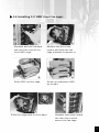
2.8 Installing 3.5" device to drive tray with power button
1
2
1
Squeeze and pull outward the tool-free clip securing the
drive tray with power button. Slide outward to remove it.
2
Squeeze both top and
bottom portion of drive
tray cover pictured top
to remove the front
cover.
3
Remove mesh from the cover.
4
Place cover back to drive tray to its
original position. Insert 3.5" device
and fasten by screws.
5
Insert back the device tray as shown
above. Squeeze and push inward the
tool-free clip to secure the device tray.
Note: Drive tray with power button
can be moved to any drive bay as
desired.
11
VH1000
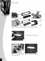
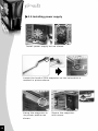
2.9 Installing power supply
1
Install power supply unit as shown.
2
Locate the hook of PSU supporter on the hole which is
marked in picture above.
3
Swing the supporter to
its proper position as
shown.
12
4
Secure the supporter
with screw.
2.10 Installing the fan on top of the case
Press-in 2 clips on
the side of fan
1
2
Align all clips with
mounting holes,
then push-in the fan
against case body
to secure it.
3
2.11 How to remove the fan & fan holder
12cm rear fan
Push fan clip upward
to loose fan, then
remove fan holder
from inside.
1
2
9cm rear fan
To remove fan & fan
holder by press-in
clips then pull both
from inside. Please
see picture as shown.
3
4
13
VH1000
2.12 Air cooling system
Top (Exhaust) :
90 x 90 x 25mm,
1800rpm, 19dBA
Front (intake) :
Rear (Exhaust) :
120 x 120 x25 mm
blue LED fan,
1300rpm, 17dBA
- 90 x 90 x 25mm,
1800rpm, 19dBA
- Rear HDD cooling
Rear (Exhaust) :
120 x 120 x25 mm
blue LED fan,
1300rpm
4-pin connector:
connect to PSU
14
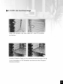
2.13 PCI slot tool-free usage
1
2
Open the plastic clip then take off the PCI bracket
as follow.
3
4
Locate Graphic Card to the motherboard through fixing
it on the space of PCI bracket and secure the Graphic
Card as shown.
15
VH1000
Chapter3 Motherboard & Leads Installation
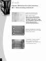
3.1 Before installing motherboard
Inside the accessory box,
please locate the Mylars
(clear plastic films).
*Note: Due to the unique
design of the Soprano Fx
Chassis, these Mylar tapes
are included to prevent ATX
motherboards from
contacting the chassis.
Remove the adhesive backing
and place the Mylars over each
locations as shown.
Completed. Please note the
Mylar tapes included are
transparent. The image here
is for reference only.
16
3.2 Motherboard installation
Each motherboard has different standoff layout. It is highly
suggested that you refer to your motherboard's manual when
installing motherboard into the Case. Soprano Fx is applicable
with Extend ATX, ATX & Micro ATX motherboards. Your motherboard
may require a special I/O Panel, which should be included with
your motherboard.
Placement Direction:
When installing the motherboard, make sure you follow the
direction provided by your motherboard manufacturer. On
most standard motherboards, the edge with external ports
goes to the rear part of the chassis. It is highly recommended
that you install CPU, heat sink and modular components
before fixing the motherboard inside the chassis.
= the locations of
the screw holes. Note
these locations and
place included
standoffs on the chassis
first.
This side towards
the rear of the
chassis
Above illustration is a sample of what
the motherboard's layout. For more
detail screw hole placement, please
refer to your motherboard manual.
17
VH1000
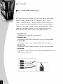
3.3 Case LED connection
On the front of the case, you can find some LEDs and
switch leads (POWER SW*1, POWER LED*1, H.D.D.
LED*1, RESET SW*1). Please consult user manual of
your motherboard manufacturer, then connect these
leads to the panel header on the motherboard. These
leads are usually labeled; if not, please trace them
back to the case front to find out their source.
- POWER LED
connects to your M/B at the PLED
- POWER SW
connects to the PWR connector on the motherboard.
- H.D.D LED
connects to the 2-pin labeled HDD LED connector.
- RESET SW
connects to the RSW connector on the motherboard
- SPEAKER
connector: find out the 4-pin labeled SPEAKER on the
M/B then connect it.
18
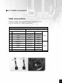
3.4 USB 2.0 connection
USB connection
Please consult your motherboard manual to find
out the section of "USB connection".
USB2.0 connection
M/B layout (Ex: ASUS)
Case layout
1
USB+5V
VCC 1
Red
2
LDM1
DATA-1
White
3
LDP1
DATA+1
Green
4
GND
GND 1
Black
5
NC
SHIELD 1
Black
6
USB+5V
VCC 2
Red
7
LDM2
DATA-2
White
8
LDP2
DATA+2
Green
9
GND
GND 2
Black
10
--
SHIELD 2
Black
USB 1
USB 2
19
VH1000
3.5 Audio connection
Please refer to the following illustration of Audio
connector and your motherboard user manual.
Please select the motherboard which used AC'97 or HD
Audio (Azalia), (be aware of that your audio supports AC'97
or HD Audio (Azalia)) or it will damage your device(s).
On some motherboards, the connectors for Audio are not
the same as the drawing below. Please check with your
motherboard manual before installing.
PORT1 L
PORT1 R
RED
BROWN
PORT2 R YELLOW
SENSE_SEND PURPLE
PORT2 L
BLUE
BLACK
AUD GND
BLACK
PRESENCE#
ORANGE SENSE1_RETURN
KEY
GREEN
SENSE2_RETURN
AUDIO AZALIA Function
Front Microphone
input Signal
MIC IN
RED
Front Microphone
Power
MIC POWER
BROWN
Front Right Channel
Audio Signal
R-OUT YELLOW
NC
Front Left Channel
Audio Signal
L-OUT
BLUE
BLACK
NC
YELLOW R-RET
Rear Right Channel
Audio Signal
KEY
BLUE
AUDIO AC'97 Function
20
Front
GROUND Audio Ground
L-RET
Rear Left Channel
Audio Signal
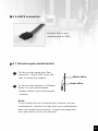
3.6 eSATA connection
Connect this to your
motherboard at SATA.
3.7 Intrusion open alarm function
1
To find out the cable with 2pin
connector ("Micro SW") from the
rear of inside the chassis.
2
To find out the position of Chassis
White Wire
Black Wire
Alarm on your motherboard.
(please consult your motherboard
manual)
Note:
If you cannot find an intrusion alert function on your
motherboard, chances are high that your motherboard
does not support this function. Please tuck away this
wire and do not utilize this function.
21
VH1000
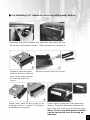
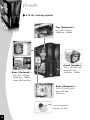
Chapter 4 Other
4.1 Toughpower / Purepower / TR2
power supply series (optional)
The Thermaltake Power Supply series specification meets latest
Intel & AMD dual & Quad core processors and NVIDIA & AMD
high performance graphic cards; it offers plenty of functions,
which mainly include:
1. Automatic Fan Speed Control: All power supply can detect the inside
heat and automatically adjust the fan speed to provide adequate airflow.
2. Ultra Silent: Ball bearing fans with high reliability 140mm or 120mm
cooling fan and super low acoustic noise under all load condition.
3. Modularized Cable Management: To eliminate clutter and improve
airflow inside the case.
4. Dedicated Graphic Card Power: reduce the loading on current PSU and
no need to upgrade current PSU while running multi graphic cards mode.
The functions can assure all Thermaltake Power Supply meets the balance in
noise control and heat exhausted. All power supply provides complete protection
function as follow:
1. Over power protection.
2. Short circuit protection on all output.
3. Over voltage protection / Under voltage protection.
4. Over current protection.
5. Over temperature protection.
Besides, Thermaltake enables the quality assurance of all power supply: 100%
Hi-POT and ATE Function Test, 100% Burn-In and AC Input cycled on/off under
high temperature condition. Furthermore, it has been approved by UL, CUL, TUV,
CB, FCC, CE, and BSMI.
There are three main products line of Thermaltake PSU which divided into
Toughpower, Purepower (include Purepower RX) and TR2 (include TR2 RX)
series. Please refer to
http://www.thermaltake.com/product/Power/power_index.asp
22
23