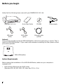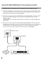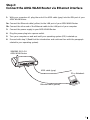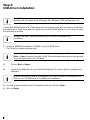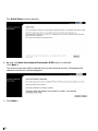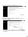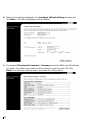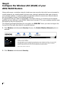
1
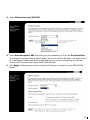
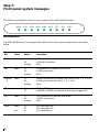
s
Quick Start Guide
SIEMENS SL2-141-I
ADSL WLAN Router
•
Do never open the housing!
•
Use only the power supply provided with this device.
•
Use only the cables provided with this device and do not
perform any modifications on them.
05-20070329
Before you begin
Verify that the following items came with your SIEMENS SL2-141-I kit:
SIEMENS SL2-141-I
Quick Start Guide
ADSL cable
(gray)
USB cable
(blue)
CD-ROM
Power supply
Ethernet cable
(yellow)
Optional:
If your service provider include an ISDN ADSL-Splitter, follow the instructions in section “Step 1:
Install the ISDN ADSL-Splitter”. If you need further assistance installing the filter, please contact
your service provider.
ISDN ADSL-Splitter
System Requirements
Before starting the installation of the ADSL WLAN Router, make sure your computer is
equipped with:
•
2
LAN interface (Ethernet) with RJ45 socket
(Windows NT4, 98, ME, 2000, XP, Vista, Mac OS 9.x, 10.x)
Step 1:
Install the ISDN ADSL Splitter
The ADSL technology uses the existing telephone line for the broadband entrance. With the
ISDN installation a ISDN ADSL-Splitter must be installed to separate the frequency ranges of
ADSL and ISDN and to prevent disturbances at ISDN phones or fax machines. Use for installation the provided ISDN ADSL-Splitter.
ISDN ADSL-Splitter
Important note:
-
With an ISDN installation only one ISDN ADSL-Splitter is needed for the entire ISDN
installation.
-
For Phones or fax machines with ADSL and ISDN there is no Line-Filter needed.
-
Please contact your support-technician if your ISDN-NT (ISDN Networkterminator) is
not equipped with a plugged incoming line.
3
Connect the ADSL WLAN Router to the exchange connection
1. Remove the plug on the telephone or the fax machine from the telephone socket.
2. Insert the ADSL-Splitter into the telephone socket. Plug the plug of the ADSL-Splitter cable
(enclosed, mostly black) into the “Phone” (F) plug of the telephone socket and the other
plug into the “Line” (Amt) plug of the ADSL-Splitter.
3. Set up the connection between the ADSL-Splitter and the ADSL Modem. To do this, insert
the end of the ADSL cable (gray) into the socket of the ADSL-Splitter with the "DSL"
(Modem) symbol.
Insert the other end of the ADSL cable (gray) into the socket on your ADSL WLAN Router
marked "DSL".
4. Set up the connection between the ADSL-Splitter and the ISDN-NT. To do this, insert the
available phone cord (same construction as the ADSL-Splitter cable) into the middle plug of
the ADSL-Splitter. The middle plug is marked with a none crossed symbol of a phone.
Connect the end of the phone cable into the “Line” plug of the ISDN-NTBAs.
Telephone socket
2.
ADSL-Splitter
4.
2.
4.
3.
3.
to the SIEMENS SL2-141-I ADSL WLAN Router
4
Step 2:
Connect the ADSL WLAN Router via Ethernet interface
1.
With your computer off, plug the end of the ADSL cable (gray) into the DSL port of your
ADSL WLAN Router.
2a. Connect the Ethernet cable (yellow) to the LAN port of your ADSL WLAN Router.
2b. Connect the other end of the Ethernet cable to the LAN port of your computer.
3.
Connect the power supply to your ADSL WLAN Router.
4.
Plug the power plug into a power outlet.
5.
Turn your computer on and wait until your operating system (OS) is started up.
6.
Proceed with step 3 (Read first the introduction and continue then with the paragraph
related to your operating system).
SIEMENS SL2-141-I
ADSL WLAN Router
3.
2a.
1.
ADSL cable (gray)
PC or Notebook
Ethernet cable (yellow)
2b.
5
Step 3:
USB driver installation
The USB driver is only working on the following operating system (OS):
Windows 98, Windows 98 SE, Windows ME, Windows 2000 and Windows XP.
If your ADSL WLAN Router is NOT equipped with an Ehternet interface you have to install first
the USB driver in order to be able to configure your ADSL WLAN Router. For the driver installation proceed as follows:
Windows 98 users need the Windows 98 CD-ROM to complete the
installation.
1. Insert the SIEMENS installation CD-ROM in your CD-ROM drive.
The CD will be startet automatically.
In case the “setup wizard” does not start automatically, open a Run window via
Start --> Run and enter the path x:\USB_Driver\windows\setup.exe, where x represents the drive letter of the CD drive.
2.
Click on Run or Setup.
3.
Connect the USB cable to your ADSL WLAN Router. The driver will be installed automatically.
Note for Windows 98 users: If prompted, you need to insert the Windows 98 CDROM in your CD-ROM drive to complete the installation.
4. You will be asked whether the PC should be restarted. Click on Close.
5. Click on Finish.
6
Step 4:
Configure the PC (TCP/IP settings)
Introduction
In step 4, you will learn how to configure your computer to communicate with the SIEMENS
ADSL WLAN Router.
To do this, you will need to configure your PC’s network settings to obtain an IP address automatically. Computers use IP addresses to communicate with each other across a network or
the Internet.
Find out which operating system your computer is running, such as Windows 98, Windows ME,
Windows NT4, Windows 2000, Windows XP, Windows Vista or Macintosh OS 9.x, 10.x.
You will need to know which operating system your computer is running. You can find out by
clicking on Start -> Settings. (If your Start menu doesn’t have a Settings option, you are running Windows XP or Windows Vista. In this case you can select the Control Panel directly from
the Start menu.) Then, click on Control Panel and double-click on the System icon.
Click the Cancel button when done.
Once you know which operating system you are running, follow the directions in this step for
your computer’s operating system.
The next few pages tell you, step by step, how to configure your TCP/IP settings based on the
type of Windows or Macintosh operating system you are using.
7
Step 4a:
Configure the PC (TCP/IP settings)
for Windows 98 and Windows ME
Windows 98 users need the Windows 98 Installation CD to complete the installation.
1. Click on Start -> Settings -> Control Panel.
Double-click on the Network icon to open the
Network screen.
2. Select the Configuration tab and highlight the
TCP/IP line for the applicable Ethernet
adapter1). If the word TCP/IP appears by itself,
select that line2). Click on Properties.
3. Click the IP Address tab and select Obtain an
IP address automatically.
4. Click on the Gateway tab and verify that the
Installed Gateway field is blank. Click on OK.
5. Click again on OK. Windows may ask you for
the original Windows Installation disk or additional files. Supply them by pointing to the correct location, e.g. D:\win98, where “D” represents the letter of your CD-ROM drive.
2
6. If Windows asks you to restart your PC, click on
Yes. If Windows does not ask, restart your
computer anyway.
3
Choose a TCP/IP entry whose name contains Ethernet adapter. Do not choose
a TCP/IP entry whose name is PPPoE, VPN or other.
1)
If there is no TCP/IP line listed, refer to the User Manual on your Aethra CD-ROM
to install TCP/IP now.
2)
8
Step 4b:
Configure the PC (TCP/IP settings)
for Windows NT4
1. Click on Start -> Settings -> Control Panel.
Double-click on the Network icon. The
Network screen will appear.
2. Select the Protocol tab and highlight the
TCP/IP line. Click on Properties.
3. Select the IP Address tab and select Obtain
an IP address from a DHCP server and click
on OK on the subsequent screens to complete the PC’s configuration.
4. When prompted with “Activate DHCP” dialog
box, click Yes.
5. Restart your computer.
2
3
9
Step 4c:
Configure the PC (TCP/IP settings)
for Windows 2000
1. Click on Start -> Settings -> Control Panel.
Double-click on the Network and Dial-up
Connections icon. The Network screen will
appear.
2. Select the Local Area Connection icon for
the applicable Ethernet adapter (usually it is
the first Local Area Connection listed).
Double-click on Local Area Connection and
click on Properties.
3. Select Internet Protocol (TCP/IP) and click
on Properties.
2
4. Select Obtain an IP address automatically
and click on OK on the subsequent screens
to complete the PC’s configuration.
5. Restart your computer.
3
4
10
Step 4d:
Configure the PC (TCP/IP settings)
for Windows XP
The following instructions assume you are running Windows XP’s default interface. If you are
using the Classical interface (where the icons and menus look like previous Windows versions), please follow the instructions for Windows 2000 (Step 4c).
1. Click on start -> Control Panel. Click on the
Network and Internet Connections icon.
Click on the Network Connections icon. The
Network screen will appear.
2. Select the Local Area Connection icon for
the applicable Ethernet adapter (usually it is
the first Local Area Connection listed).
Double-click on Local Area Connection and
click on Properties.
3. Select Internet Protocol (TCP/IP) and click
on Properties.
2
4. Select Obtain an IP address automatically
and click on OK on the subsequent screens
to complete the PC’s configuration.
5. Restart your computer.
3
4
11
Step 4e:
Configure the PC (TCP/IP settings)
for Windows Vista
1. Click on start -> Control Panel. Click on
the Network and Sharing Center icon.
Click on Broadband Connections →
Properties.
2. The “Local Area Connection Status”
screen will appear. Click on the
Properties button.
3. Select Internet Protocol Version 4
(TCP/IPv4) and click on Properties.
4. Select Obtain an IP address automatically and click on OK to complete the
PC’s configuration.
2
5. Click on the OK to finish the configuration.
3
4
12
Step 4f:
Configure the PC (TCP/IP settings)
for Mac OS 9.x
1. From the Apple Menu, point to
Control Panels and then click TCP/IP.
2. From the Connect via pull-down
menu select Ethernet built-in. From
the Configure pull-down menuselect
Using DHCP Server.
3. Close the TPC/IP window and click on
[Save].
13
Step 4g:
Configure the PC (TCP/IP settings)
for Mac OS X
1. From the Apple Menu, select System
Preferences...
2. Click on the Network icon in the Internet
& Network area.
3. From the Show pull-down select Built-in
Ethernet. On the TCP/IP tab, select Using
DHCP from the Configure pull-down
menu.
4. On the PPPoE tab, make sure that the
Connect using PPPoE check box is NOT
activated. Click Apply Now.
2
5. Close the Network window.
3
4
14
Step 5:
Configure the ADSL WLAN Routers (Internet Access)
1. Start your web browser (e.g. Internet Explorer) and type 192.168.1.1 in the address field
of the browser. Press Enter. Enter in the field <Username> admin and in the field
<Password> admin as well and click Next>.
2. The Quick Setup window appears:
If the Quick Setup page is not displayed, please check the TCP/IP settings of your
computer (obtain IP address automatically must be enabled). Find more information about the configuration in chapter 4.
Enter your username and password, which you can get from your provider, and click
Connect>. The connection to the Internet will be established.
If the connection to the Internet won’t be established, please proceed with step 3
and follow the instructions provided in this guide for basic installation.
3. Click on Quick Setup on the left side of the window “Quick Start”.
15
The Quick Setup window appears:
4. Be sure, the Auto Scan Internet Connection (PVC) option is selected.
Click Next >.
The scanning process will be started and can take several minutes. Afterwards the
detected connection will be displayed.
5. Click Next >.
16
The Configure Internet Connection - WAN IP Settings window appears:
6. Select Optain an IP address automatically and enable NAT. Type 1492 in the
MTU: field and click Next >.
The following window appears:
7. For <PPP User Name> enter the username and for <PPP Password> the password.
You can get this information from your Internet Service Provider. Select Always On
and click Next >.
17
8. Take over the settings displayed in the Configure LAN side Settings window and
click Next >. The LAN configuration will be started.
9. The window This Internet Connection - Summary shows the WAN and LAN settings
you made. The values must match to those values you get from your ISP. Click
Finish to accept these settings and to terminate the configuration.
18
10. The installation is done and your ADSL WLAN Router will reboot. This will take about 1-2
minutes.
11. The window Connect to Internet appears. If needed, enter the username and password
and click Connect>. The connection to the Internet will be established.
19
Step 6:
Configure the Wireless LAN (WLAN) of your
ADSL WLAN Routers
Using radio waves, a wireless network introduces some security risks which are not present in
a wired network; an unauthorized third party can intercept transmitted data, gain access to
your wireless network. In order to make your wireless network as secure as a wired network
you should apply, at least, the following guidelines.
To guarantee that your data is transmitted in a private manner, you should use the highest
possible security settings in your WLAN. Make sure that each PC on your wireless network uses
the same key as your access point.
The following example illustrates the encryption via ‘WPA-PSK’. Note: you must configure the
Access Point first and after that all connected devices.
1. Click Wireless and afterwards Security. Be sure, the Enable Wireless Network option is
selected.
1
1
2
2. Click Wireless and afterwards Security.
20
3. Select Wireless Security: WPA-PSK.
4. Select Data Encryption: AES and enter your key (password) in the field Pre-Shared Key:.
The choosen key must have at least 8 digits, but not more than 64 digits. Use digits from 0
to 9 and letters. Please keep this key safe and be sure you are configuring your Access
Point(s) with the same key as your ADSL WLAN Router.
5. Click Apply. Afterwards you must configure all devices connected to your ADSL WLAN
Router.
21
Step 7:
Front panel system messages
The following illustration shows the front panel of the ADSL WLAN Routers:
WLAN
USB
LAN4 LAN3 LAN2 LAN1
PPP
DSL
PWR
LED Indicators
The ADSL WLAN Router is equipped with LEDs on the front panel as described in the table
below:
LED
Colour
Status
Description
WLAN
Green
On
Off
blinking
WLAN connection is present and active
No WLAN connection
Traffic
USB
Green
On
Off
blinking
USB connection is present and active
No USB connection
Traffic
Ethernet Green
1-4
On
Off
blinking
Ethernet connection is present and active (Port 1, 2, 3 or 4)
No Ethernet connection (Port 1, 2, 3 or 4)
Traffic
PPP
Green
On
Off
PPPoE or PPPoA connection is present
No PPPoE or PPPoA connection or the user is logged off
DSL
Green
On
Off
blinking
ADSL connection is present and active
No ADSL connection
Traffic
Power
Green
On
Off
On
Unit is powered on
Unit is powered off
Unit is initializing
Red
22
s
Siemens Switzerland Ltd
Information and Communication Products
Albisriederstrasse 245
CH-8047 Zurich
Declaration of Conformity
We hereby declare that the product:
SIEMENS ADSL SL2-141 (ADSL2+ Router for POTS), S1621-Z121-A
SIEMENS ADSL SL2-141-I (ADSL2+ Router for ISDN), S1621-Z120-A
(Name of product, type or model, batch or serial number)
is in conformity with the following standards:
ETSI EN 300 328 V1.6.1(2004), EN 50385:2002 :SAR
ETSI EN 301 489-1 V1.4.1:2002/ ETSI EN 301 489-17 V1.2.1:2002
RFI Emission:
EN 55022 :1998 + A1 : 2000+A2:2003 Class B:
EN 61000-3-2: 2000 Class A
EN 61000-3-3:1995+A1: 2001:
: Conducted and radiated test
: Limits for harmonic current emission
: Limitation of voltage fluctuation and flicker
in low-voltage supply system
Immunity:
EN 55024:1998+A1:2001+A2:2003
IEC 61000-4-2:1995+A1: 1998+A2:2000+A2:2001
IEC 61000-4-3:2002+A1:2002
IEC 61000-4-4:1995+A1:2000+A2:2001
IEC 61000-4-5:1995+A1:2000+A1:2001
IEC 61000-4-6:1996+A1:2000+A1:2001
IEC 61000-4-11:1994+A1: 2000+A1:2001
: Immunity standard
: ESD
: RS
: EFT
: Surge
: CS
: Voltage Dips
We hereby verify that: The equipment above listed has tested for compliance with The
European Council Directive 89/336/EEC. & The Low Voltage Directive 73/23/EEC. and The
Amendment Directive 93/68/EEC. and Radio & Telecommunications Terminal Equipment
Directive(R&TTE) 1999/5/EC. Note: Full test report are available if required.
Zurich, 25.11.05
(place and date of issue)
Daniel Ebinger, VP Broadband Division
(names and signatures of authorized persons)
23
24