1
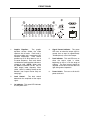
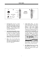
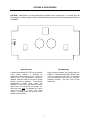
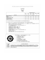
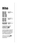
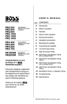
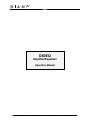
blank
D60EQ
Amplifier/Equalizer
Operation Manual
Biamp Systems | 9300 S.W. Gemini Drive | Beaverton, OR | 97008 | USA | +1.503.641.7287 | www.biamp.com
19Mar07
D60EQ
TABLE OF CONTENTS
INTRODUCTION
Safety Information
pg. 2
Front Panel Features
pg. 6
Rear Panel Features
pg. 7
The D60EQ is an integrated power amplifier, distribution autoformer, and
9-band graphic equalizer, ideally suited for paging/background music
systems, as well as for zone systems in church, theater, restaurant and
hotel applications. The D60EQ is easy to install, and is covered by a
five-year warranty.
Options & Accessories
pg. 8
D60EQ features include:
Block Diagram & Specifications
pg. 9
♦ integrated equalizer, amplifier, and distribution autoformer
Warranty
pg. 10
♦ electronically balanced differential line level input stage
♦ 9-band graphic equalizer (±15dB on ISO center frequencies)
♦ 60W of power into 4Ω, 8Ω, or distributed speaker systems
♦ HPF (18dB/octave @ 180Hz) selectable with internal jumper
♦ passively cooled amplifier eliminates fan noise/maintenance
♦ complete short-circuit and thermal protection with auto-reset
♦ turn-on muting to provide noiseless power switching
♦ front panel indicators for power, signal present, and peak
♦ input/output connections provided on barrier strip terminals
♦ table-top design with rack-mounting kit included
♦ covered by Biamp Systems' five-year warranty
1
IMPORTANT SAFETY INSTRUCTIONS
Read these instructions.
Do not install near any heat sources such as
radiators, heat registers, stoves, or other apparatus
(including amplifiers) that produce heat.
Keep these instructions.
Heed all warnings.
Do not defeat the safety purpose of the polarized or
grounding-type plug. A polarized plug has two
blades with one wider than the other. A grounding
type plug has two blades and a third grounding
prong. The wide blade or the third prong are
provided for your safety. When the provided plug
does not fit into your outlet, consult an electrician
for replacement of the obsolete outlet.
Follow all instructions.
Do not use this apparatus near water.
Clean only with a dry cloth.
Do not block any of the ventilation openings.
Protect the power cord from being walked on or
pinched particularly at plugs, convenience
receptacles, and the point where they exit from the
apparatus.
Install in accordance with the manufacturers
instructions.
WARNING - To reduce the risk of electric shock, do
not expose this apparatus to rain or moisture.
Refer all servicing to qualified service personnel.
Servicing is required when the apparatus has been
damaged in any way, such as power-supply cord
or plug is damaged, liquid has been spilled or
objects have fallen into the apparatus, the
apparatus has been exposed to rain or moisture,
does not operate normally, or has been dropped.
The apparatus shall not be exposed to dripping or
splashing and no objects, such as vases, shall be
placed on the apparatus.
Unplug this apparatus during lightning storms or
when unused for long periods of time.
Use only attachments/accessories specified by the manufacturer.
Use only with the cart, stand, tripod, bracket, or table specified by the manufacturer or sold with the apparatus.
When a cart is used, use caution when moving the cart/apparatus combination to avoid injury from tip-over.
Unplug this apparatus during lightning storms or when unused for long periods of time.
The appliance inlet shall be readily operable once installed.
WARNING - Terminals marked with the following symbol are Hazardous. Connections to these teminals must be
made by qualified personnel.
2
3
4
5
FRONT PANEL
1.
Graphic Equalizer.
The graphic
equalizer section divides the audio
spectrum into 9 bands. Each band is
one octave wide and is centered on ISO
standard frequencies.
Each control
provides up to 15 dB of boost or cut at
its center frequency. Each mark above
and below the center position indicates a
change of 3 dB. NOTE: When using
the D60EQ autoformer (for 8Ω, 70V, or
100V output) lower frequency filters
(64Hz, 125Hz, & 250Hz) should not be
boosted (see Output Barrier Strip on
next page).
2.
Level Control.
The level control
determines the amplitude of the output
signal.
3.
On Indicator. This green LED indicates
that AC power is on.
6
4.
Signal Present Indicator. This green
LED turns on when the output signal is
greater than or equal to approximately
-20 dBu (80 mv) at the 4 ohm output.
5.
Peak Indicator. This red LED turns on
when the output signal is either
beginning to clip or is on the verge of
clipping. The level control should be
adjusted so the Peak Indicator does not
light during normal operation.
6.
Power Switch. Turns on or off the AC
power to the unit.
REAR PANEL
common
input +
4Ω
115V
115/230 VAC
D60EQ
autoformer
input
115V: 2A SB fuse
230V: 1A SB fuse
BIAMP SYSTEMS
input –
gnd
Designed in Oregon, U.S.A.
Assembled in India
8Ω
70V
E * F
SE *
* FU
U
S
100V
FU
SE
50/60 Hz 160 Watts
1.
AC Power Cord. Connect to ~115/230
VAC 50/60 Hz AC power. Make sure
that the line voltage selector switch and
fuse have been correctly set before
plugging in. Do not remove or defeat
the AC ground prong on the plug, as this
constitutes a shock hazard.
2.
Line Voltage Selector Switch. Set this
switch to "115" for nominal line voltages
of 110-120 VAC. Set this switch to "230"
for nominal line voltages of 220-240
VAC. Make sure that the appropriate
fuse is installed when changing voltage
selections. The unit is set for 115 volt
operation when shipped from the factory.
3.
Fuse. This is the AC power fuse.
Replace fuse only with same type and
value. For 115 volt operation, use a T
2A L 250V fuse. For 230 volt operation,
use a T 1A L 250V fuse.
7
4.
Output Barrier Strip.
The output
barrier strip provides connections for the
output of the amplifier. The Common
terminal is the output "ground"
connection. When the unit is shipped
from the factory, the distribution
autoformer is not hooked up and signal
is only present at the 4 ohm output. To
use the 8Ω, 70V, or 100V outputs, the
jumper wire must be connected from the
4Ω output terminal to the autoformer
input terminal. NOTE: From the factory,
the D60EQ has an 18dB/octave 180Hz
high-pass filter enabled. This high-pass
filter must remain enabled whenever an
autoformer output is being used (8Ω,
70V, or 100V). The high-pass filter
should be disabled only when using the
‘direct’ 4Ω output (see Options &
Accessories on page 8). CAUTION:
High voltages may be present at the
output terminals. Be sure that the AC
power is off when making connections.
5.
Input Barrier Strip. The input barrier
strip provides connections for the
balanced input to the amplifier. The
bottom three terminals on this barrier
strip are unused.
OPTIONS & ACCESSORIES
CAUTION: Modifications must be performed by qualified service professionals. AC power must be
disconnected, and the top panel must be removed before performing any of the following modifications to
the D60EQ.
FILTER
IN
OUT
High-Pass Filter
Rack Mounting
A jumper strap labelled ‘FILTER’ on the amplifier
circuit board enables or disables an
18dB/octave 180Hz high-pass filter. When the
strap is in the "IN" (up) position, the filter is
enabled. When the strap is in the "OUT" (down)
position, the filter is disabled. To avoid high
magnetization currents which cause the
amplifier to current limit and distort the output
signal when low frequencies are present, the
high pass filter must be strapped "IN" when
using the autoformer (8 ohm, 70V, 100V)
outputs. This strap is set "IN" when the unit is
shipped from the factory.
Rack mounting brackets are provided with the
D60EQ. To install these brackets, the top cover
of the unit must first be removed. The brackets
are then attached to the top cover using the
hardware supplied. The top cover is then
reattached.
8
BLOCK DIAGRAM & SPECIFICATIONS
D60EQ Block Diagram
Signal
Present
64 125 250 500 1k 2k 4k 8k 16k
Input
HPF
+
Signal
Detect
Level
Output
Out
Gnd
Peak
Common
4Ω Out
Xfmr In
8Ω Out
70V Out
100V Out
9-band graphic equalizer
Balanced
input Stage
In
HPF 180Hz
18dB/octave
Driver
Amplifier
Power
Amplifier
Distribution
Autoformer
_________________________________ SPECIFICATIONS _________________________________
AMPLIFIER SECTION:
Output Power (2kHz @ 0.2% THD)
>60 watts
Frequency Response (20Hz-20kHz @ 60W)
+0/-1.5dB
Total Harmonic Distortion (20Hz-20kHz @ 60W)
Intermodulation Distortion (SMPTE)
<0.2%
<0.35%
Signal-to-Noise Ratio (20Hz-20kHz @ 60W)
>89dB
Input Sensistivity
.775 Volts
Input Impedance
balanced
unbalanced
20k ohms
10k ohms
INTERNAL AUTOFORMER:
Frequency Response (150Hz-20kHz @ 60W/70V output)
Total Harmonic Distortion (2kHz @ 60W/70V output)
EQUALIZER SECTION:
Filter Gain
+0/-3dB
<0.2%
+/-15dB
Center Frequencies
64Hz, 125Hz, 250Hz,
500Hz, 1kHz, 2kHz,
4kHz, 8kHz, 16kHz
Power Requirements
115/230VAC 50/60Hz
Power Consumption
160 watts max.
Dimensions
Height (2 rack spaces)
Width
Depth
3.5 inches (89mm)
10.2 inches (259mm)
11.4 inches (290mm)
Weight
15 lbs. (6.81kg)
9
WARRANTY
BIAMP SYSTEMS IS PLEASED TO EXTEND THE FOLLOWING 5-YEAR LIMITED WARRANTY TO THE
ORIGINAL PURCHASER OF THE PROFESSIONAL SOUND EQUIPMENT DESCRIBED IN THIS MANUAL
1. BIAMP Systems warrants to the original purchaser of new
products that the product will be free from defects in material
and workmanship for a period of 5 YEARS from the date of
purchase from an authorized BIAMP Systems dealer, subject to
the terms and conditions set forth below.
5.
THIS WARRANTY IS IN LIEU OF ALL OTHER
WARRANTIES, EXPRESS OR IMPLIED. BIAMP SYSTEMS
DISCLAIMS ALL OTHER WARRANTIES, EXPRESS OR
IMPLIED, INCLUDING, BUT NOT LIMITED TO, IMPLIED
WARRANTIES OF MERCHANTABILITY AND FITNESS FOR A
PARTICULAR PURPOSE.
2. If you notify BIAMP during the warranty period that a BIAMP
Systems product fails to comply with the warranty, BIAMP
Systems will repair or replace, at BIAMP Systems' option, the
nonconforming product. As a condition to receiving the benefits
of this warranty, you must provide BIAMP Systems with
documentation that establishes that you were the original
purchaser of the products. Such evidence may consist of your
sales receipt from an authorized BIAMP Systems dealer.
Transportation and insurance charges to and from the BIAMP
Systems factory for warranty service shall be your responsibility.
6. The remedies set forth herein shall be the purchaser's sole
and exclusive remedies with respect to any defective product.
7. No agent, employee, distributor or dealer of Biamp Systems
is authorized to modify this warranty or to make additional
warranties on behalf of Biamp Systems.
statements,
representations or warranties made by any dealer do not
constitute warranties by Biamp Systems. Biamp Systems shall
not be responsible or liable for any statement, representation or
warranty made by any dealer or other person.
3. This warranty will be VOID if the serial number has been
removed or defaced; or if the product has been altered,
subjected to damage, abuse or rental usage, repaired by any
person not authorized by BIAMP Systems to make repairs; or
installed in any manner that does not comply with BIAMP
Systems' recommendations.
8. No action for breach of this warranty may be commenced
more than one year after the expiration of this warranty.
9. BIAMP SYSTEMS SHALL NOT BE LIABLE FOR SPECIAL,
INDIRECT, INCIDENTAL, OR CONSEQUENTIAL DAMAGES,
INCLUDING LOST PROFITS OR LOSS OF USE ARISING
OUT OF THE PURCHASE, SALE, OR USE OF THE
PRODUCTS, EVEN IF BIAMP SYSTEMS WAS ADVISED OF
THE POSSIBILITY OF SUCH DAMAGES.
4. Electro-mechanical fans, electrolytic capacitors, and normal
wear and tear of items such as paint, knobs, handles, and
covers are not covered under this warranty.
Biamp Systems
9300 S.W. Gemini Drive
Beaverton, Oregon 97008
(503) 641-7287
585.0062.90A
10