1
Release Note
Software Version 2.7.6
For AT-8800, Rapier i, AT-8700XL, AT-8600,
AT-9900, AT-8900 and AT-9800 Series Switches and
AR400 and AR700 Series Routers
Introduction .......................................................................................................2
Upgrading to Software Version 2.7.6 .................................................................3
Overview of New Features .................................................................................4
Support for AT-8648T/2SP Switch ....................................................................... 5
Enhancements to CLI Help .................................................................................6
Listing commands and valid parameters ..................................................... 7
Completing parameters .............................................................................. 8
Listing valid options .................................................................................... 8
Command Change Summary ..................................................................... 8
DHCP Snooping ................................................................................................. 9
Overview .................................................................................................... 9
The DHCP snooping binding database ........................................................ 9
DHCP Filtering .......................................................................................... 11
DHCP Option 82 ...................................................................................... 11
DHCP Snooping ARP Security ................................................................... 12
Command Reference Updates .................................................................. 14
Deleting Dynamic ARP Entries ..........................................................................30
Command Change Summary ................................................................... 30
Command Reference Updates .................................................................. 31
Redistributing BGP Routes into RIP ...................................................................32
Filtering BGP Routes When Redistributing ................................................. 32
Command Change Summary ................................................................... 34
Command Reference Updates .................................................................. 35
Classifying On Layer 4 Port Range ....................................................................40
Command Change Summary ................................................................... 40
Command Reference Updates .................................................................. 41
Firewall Enhancements ..................................................................................... 46
Session Monitoring ................................................................................... 46
Enhanced Network Address and Port Translation (ENAPT) ......................... 50
Command Reference Updates .................................................................. 53
Reverse Telnet Without Authentication ............................................................63
Command Reference Updates .................................................................. 64
2
Introduction
Release Note
Introduction
Allied Telesyn announces the release of Software Version 2.7.6 on the products
in the following table. This Release Note describes the new features and
enhancements.
Product series
Models
AT-9900
AT-9924T, AT-9924SP, AT-9924T/4SP
AT-8900
AT-8948
AT-9800
AT-9812T, AT-9816GB
Rapier i
Rapier 24i, Rapier 48i, Rapier 16fi
AT-8800
AT-8824, AT-8848
AT-8700XL
AT-8724XL, AT-8748XL
AT-8600
AT-8624T/2M, AT-8624PoE, AT-8648
AR700
AR725, AR745, AR750S
AR400
AR440S, AR441S, AR450S
The product series that each feature and enhancement applies to are shown in
“Overview of New Features” on page 4. This Release Note should be read in
conjunction with the Installation and Safety Guide or Quick Install Guide,
Hardware Reference, and Software Reference for your switch or router. These
documents can be found on the Documentation and Tools CD-ROM packaged
with your switch or router, or:
www.alliedtelesyn.com/support/software
This Release Note has the following structure:
1.
Upgrading to Software Version 2.7.6
This section lists the names of the files that may be downloaded from the
web site.
2.
Overview of New Features
This section lists the new features and shows the product families on which
each feature is supported.
3.
Descriptions of New Features
These sections describe how to configure each new feature.
Caution: Information in this document is subject to change without notice and
does not represent a commitment on the part of Allied Telesyn Inc. While every
effort has been made to ensure that the information contained within this
document and the features and changes described are accurate, Allied Telesyn
Inc. can not accept any type of liability for errors in, or omissions arising from,
the use of this information.
Software Version 2.7.6
C613-10462-00 REV A
Software Version 2.7.6
3
Upgrading to Software Version 2.7.6
Software Version 2.7.6 is available as a flash release that can be downloaded
directly from the Software/Documentation area of the Allied Telesyn website:
www.alliedtelesyn.com/support/software
Software versions must be licenced and require a password to activate. If you
upgrade to Software Version 2.7.6 from any 2.7.x version, your existing licence
is valid for 2.7.6. Otherwise, to obtain a licence and password, contact your
authorised Allied Telesyn distributor or reseller.
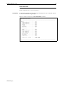
The following table lists the file names for Software Version 2.7.6.
Product name
Release file
GUI resource file
CLI help file
AT-9924T
89-276.rez
d9924e27.rsc
89-276a.hlp
AT-9924SP
89-276.rez
d9924e27.rsc
89-276a.hlp
AT-9924T/4SP
89-276.rez
d9924e27.rsc
89-276a.hlp
AT-8948
89-276.rez
—
89-276a.hlp
AT-9812T
sb-276.rez
d9812e27.rsc
98-276a.hlp
AT-9816GB
sb-276.rez
d9816e27.rsc
98-276a.hlp
Rapier 24i
86s-276.rez
dr24ie27.rsc
rp-276a.hlp
Rapier 48i
86s-276.rez
dr48ie27.rsc
rp-276a.hlp
Rapier16fi
86s-276.rez
dr16ie27.rsc
rp-276a.hlp
AT-8824
86s-276.rez
d8824e27.rsc
88-276a.hlp
AT-8848
86s-276.rez
d8848e27.rsc
88-276a.hlp
AT-8724XL
87-276.rez
d8724e27.rsc
87-276a.hlp
AT-8748XL
87-276.rez
d8748e27.rsc
87-276a.hlp
AT-8624PoE
sr-276.rez
—
86-276a.hlp
AT-8624T/2M
sr-276.rez
dsr24e27.rsc
86-276a.hlp
AT-8648T/2SP
sr-276.rez
—
86-276a.hlp
AR750S
55-276.rez
d750se27.rsc
700-276a.hlp
AR725
52-276.rez
d_725e27.rsc
700-276a.hlp
AR745
52-276.rez
d_745e27.rsc
700-276a.hlp
AR440S
54-276.rez
d440se27.rsc
400-276a.hlp
AR441S
54-276.rez
d441se27.rsc
400-276a.hlp
AR450S
54-276.rez
d450se27.rsc
400-276a.hlp
Software Version 2.7.6
C613-10462-00 REV A
4
Overview of New Features
Release Note
Overview of New Features
DHCP Snooping
AT-9900
AT-8900
AT-9800
AT-8600
!
Support for AT-8648T/2SP Switch
Enhancements to CLI Help
AT-8700XL
AT-8800
Rapier
AR750S
AR7x5
AR400
The following table lists the new features and enhancements by product series.
For supported models, see “Introduction” on page 2.
! ! ! ! ! ! ! ! ! !
! ! ! !
! !
Deleting Dynamic ARP Entries
! ! ! ! ! ! ! ! ! !
Redistributing BGP Routes into RIP
! ! ! ! !
! ! !
! !
Classifying On Layer 4 Port Range
Firewall: Session Monitoring
! ! ! ! !
! !
Firewall: Enhanced Network Address and Port Translation (ENAPT)
! ! ! ! !
! !
Reverse Telnet Without Authentication
! ! ! !
!
Software Version 2.7.6
C613-10462-00 REV A
Software Version 2.7.6
5
Support for AT-8648T/2SP Switch
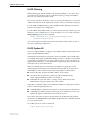
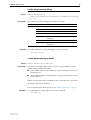
Software Release 2.7.6 supports the new AT-8648T/2SP switch.
The AT-8600 Series switches are Layer 3 switches with Layer 2/3/4+
intelligence. These desktop multimedia switches bring a high level of security
and traffic control to the edge of your network.
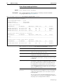
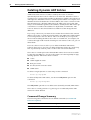
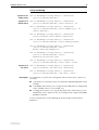
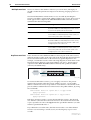
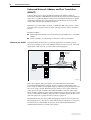
The new AT-8648T/2SP is a 48-port 10BASE-T/100BASE-TX Layer 3 Fast
Ethernet Switch.
AT-8648T/2SP hardware description
•
48-port 10BASE-T/100BASE-TX (RJ-45 connectors)
•
Two Gigabit uplink ports, SFP or Copper
•
Auto-negotiating Advanced Fast Ethernet Switch
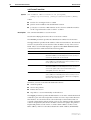
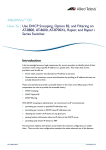
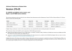
Figure 1: AT-8648T/2SP front and rear panel
LINK
49
49R MODE
LINK
AT-8648T/2SP Layer 3 Fast Ethernet Switch
CLASS 1
LASER PRODUCT
DO NOT STARE
INTO BEAM
STATUS
SFP
LINK
50
LINK
50R MODE
FLT
SPD
MSTR
FDX
RPS
ACT
PWR
MODE
The latest Hardware Reference can be found at
www.alliedtelesyn.com/support/software.
Software Version 2.7.6
C613-10462-00 REV A
COL
6
Enhancements to CLI Help
Release Note
Enhancements to CLI Help
Allied Telesyn routers and switches offer a number of methods of getting
online command help:
■
pressing the Tab key, to list valid command parameters and, if possible,
complete parameters. This functionality is new in Software Version 2.7.6,
and also provides helpful descriptions for a number of parameters
■
pressing the ? key, to list valid command parameters. With Software
Version 2.7.6, helpful descriptions are also listed for a number of
parameters
■
pressing the Tab or ? keys to list valid options for parameters
■
pressing Ctrl+c to list previously-used commands and select from the list
■
pressing Ctrl+r to search through the command history for matching
commands. In earlier software versions, the Tab key performed this
function
■
using the up and down arrow keys to scroll through the command history
■
entering the help command, to list the full syntax of all commands that are
valid for a given topic
In earlier software releases, the Tab key searched through the command history
for matching commands. To do this with Software Version 2.7.6, use Ctrl+r
instead.
The following sections give examples of the new functionality.
The examples are from an AR450S router. Some of the displayed commands
may not be valid on your router or switch model.
Note that the ? or Tab key does not display on screen. The following figures
include a ? or the word <Tab> to show what to type.
Software Version 2.7.6
C613-10462-00 REV A
Software Version 2.7.6
7
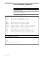
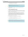
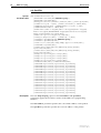
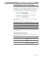
Listing commands and valid parameters
You can now use either the Tab key or the ? key to find out which parameters
you can type next, as summarised in the following table
To...
Press Tab or ? key after...
Example
List all top-level command keywords with
a one-line description of each
The blank command prompt
Figure 2
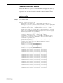
List all parameters that can complete the
command, with a one-line description of
some
A parameter and a space
Figure 3
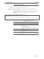
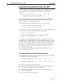
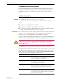
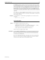
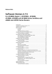
Figure 2: Listing all top-level command keywords with the question mark
Manager >?
ACTivate
Cause an action to be taken immediately
ADD
Add new items to existing objects or instances
CLear
Erase memory (NVS or FLASH) totally - use with extreme caution!
Connect
Connect to a named Telnet or interactive host service or asyn port
COPy
Copy a file in NVS or FLASH memory
CREate
Make a new object or new instance of an object
DEACTivate
Cause an action in progress to stop immediately
DELete
Remove items from existing objects or instances
DESTroy
Remove an object or an instance of an object
DISable
Suspend the operation of an object but keep its configuration
Disconnect
Terminate a session to a Telnet or interactive host service
DUMP
Display the contents of a memory location for diagnostic purposes
EDit
Invoke the built-in text editor to edit a file
ENAble
Allow an object to enter its operational state
FINGer
Send a finger query to the finger server on the specified host
FLUsh
Force the queue of log messages to be processed and emptied
Help
Display online help for the command line interface
LOAd
Transfer a file from a remote server to FLASH or NVS memory
LOGIN
Log on to the CLI and be authenticated as an authorised user
LOgoff
Log out of the CLI, to prevent unauthorised access to the CLI
--More-- (<space> = next page, <CR> = one line, C = continuous, Q = quit)
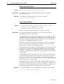
Figure 3: Listing valid parameters with the Tab key
Manager > add ospf range=192.168.1.0 <Tab>
AREa
EFFect
MASK
Manager > add ospf range=192.168.1.0
Software Version 2.7.6
C613-10462-00 REV A
8
Enhancements to CLI Help
Release Note
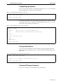
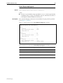
Completing parameters
You can now use the Tab key to complete parameters (Figure 4). You must first
type enough letters to match only one parameter.
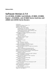
Figure 4: Completing a parameter with the Tab key
Manager > add ospf ra<Tab>
Manager > add ospf range
If you press the Tab key without first typing enough letters to uniquely identify
a parameter, the router or switch lists all matching parameters (Figure 5). This
is the same as the existing ? key behaviour.
Figure 5: Listing matching parameters with the Tab key
Manager > a<Tab>
ACTivate
ADD
Cause an action to be taken immediately
Add new items to existing objects or instances
Manager > a
Manager > add ospf r<Tab>
RANge
REDistribute
Manager > add ospf r
Listing valid options
You can now use the Tab key to list parameter options, by typing it after the
parameter and an equals sign (Figure 6). This is the same as the existing ? key
behaviour.
Figure 6: Listing options with the Tab key after parameter=
Manager > add ospf range=<Tab>
required - an IP address in dotted decimal notation
Manager > add ospf range=
Command Change Summary
There are no changes to commands for this enhancement.
Software Version 2.7.6
C613-10462-00 REV A
Software Version 2.7.6
9
DHCP Snooping
In Software Release 2.7.6, DHCP snooping has been added to provide an extra
layer of security via dynamic IP source filtering. Snooping filters out messages
received from unknown, or “untrusted” ports, and builds and maintains a
DHCP snooping binding database.
DHCP snooping is disabled by default, and is user configurable.
Overview
Dynamic Host Configuration Protocol (DHCP) dynamically assigns IP
addresses to client devices. The use of dynamically assigned addresses requires
traceability, so that a service provider can determine which clients own a
particular IP address at a certain time.
With DHCP snooping, IP sources are dynamically verified, and filtered
accordingly. IP packets that are not sourced from recognised IP addresses are
filtered out. This ensures the required traceability.
Trusted and untrusted
ports
Enabling and disabling
DHCP snooping
DHCP snooping blocks unauthorised IP traffic from untrusted ports, and
prevents it from entering the trusted network. Ports on the switch are classified
as either trusted or untrusted:
■
Trusted ports receive only messages from within your network.
■
Untrusted ports receive messages from outside your network.
To enable DHCP snooping on the switch, use the command:
enable dhcpsnooping
To disable DHCP snooping on the switch, use the command:
disable dhcpsnooping
The DHCP snooping binding database
When you enable DHCP snooping, the switch snoops client DHCP lease
information and records it in a DHCP snooping binding database.
The binding database contains current, dynamically allocated IP addresses.
When you enable DHCP snooping, the switch intercepts all DHCP packets it
receives, and sends them to the Central Processing Unit (CPU) where they are
verified. The binding database stores and maintains this information, and
installs IP source filters on ports associated with client leases.
Software Version 2.7.6
C613-10462-00 REV A
10
DHCP Snooping
Lease structure
Database structure
Release Note
Each lease in the database holds the following information:
■
the MAC address of the client device
■
the IP address that was allocated to that client
■
time until expiry
■
VLAN to which the client is attached
■
port to which the client is attached
The binding database is split into three sections:
■
current valid entries
■
entries with client lease but no listener.
Listeners are processes within the switch that use the information
contained in entries. The Classifier module is the listener that receives
information from DHCP snooping.
■
entries with no client lease and no listeners.
For more information about these database sections, see the show
dhcpsnooping database command on page 26.
Adding static entries
Although the switch dynamically adds information to the binding database,
you can also optionally add static entries to the database. This is typically used
to add a DHCP snooping entry for a client that has a preconfigured IP address
on an untrusted port. To do this, use the command:
add dhcpsnooping binding interface=vlan ip=ipadd
port=port-number
Configuring a check
interval
You can configure a check interval, in seconds, for the binding database. This
determines how often dynamic entries are checked for expiration. Expired
entries are automatically deleted from the database.
Static entries defined with the add dhcpsnooping binding command on
page 14 are not checked.
To configure a check interval for the binding database, use the command:
set dhcpsnooping checkinterval=1..3600
The switch receives expiry information with the client lease. Entries expire
when the time left to expiry is 0 seconds.
All dynamic entries remaining in the database after each check are written to
the bindings.dsn file. Whenever DHCP snooping is enabled using the enable
dhcpsnooping command on page 18, the DHCP snooping binding database is
recreated. Any entries that are still current are added to the database.
To view the current DHCP snooping binding database, use the command:
show dhcpsnooping database
Software Version 2.7.6
C613-10462-00 REV A
Software Version 2.7.6
11
DHCP Filtering
DHCP filtering prevents IP addresses from being falsified or “spoofed”. This
guarantees that customers cannot avoid detection by spoofing an IP address
that was not actually allocated to them.
The switch only allows packets to enter via a given port if they have a source IP
address that matches an IP address allocated to a device connected to that port.
For AT-8600, AT-8700XL, Rapier, and AT-8800 switches, filtering is automatic
and does not require any configuration.
For AT-8900 and AT-9900 switches, you must create classifiers and incorporate
them into a QoS configuration. To create classifiers, use one or both of the new
dhcpsnooping options in the command:
create classifier=rule-id [macsaddress=dhcpsnooping]
[ipsaddress=dhcpsnooping]
You can treat these classifiers like all other classifiers, and use them as part of
any QoS or filtering configuration.
DHCP Option 82
You can configure DHCP snooping to insert DHCP Option 82 information into
client-originated DHCP packets.
Trusted network elements insert Option 82 into the DHCP options field when
forwarding client-originated BOOTP/DHCP packets to a DHCP server. DHCP
servers that are configured to recognise Option 82 may use the information to
implement IP addresses, or other parameter assignment policies, based on the
network location of the client device.
When you enable Option 82 information for DHCP snooping, the switch
inserts Option 82 information into BOOTP request packets received from an
untrusted port. The switch inserts the following Option 82 information:
■
Remote-ID. This specifies the MAC address of the switch.
■
Circuit-ID. This specifies the switch port and VLAN-ID that the
client-originated DHCP packet was received on.
■
Subscriber-ID (optional). This is a string of up to 50 characters that
differentiates or groups client ports on the switch.
Regardless of whether Option 82 is enabled for DHCP snooping, if the switch
receives a BOOTP request packet on:
■
an untrusted port, it drops the packet if it contains Option 82 information
■
a trusted port, and the packet contains Option 82 information, it does not
update the Option 82 information for the receiver port
The switch only removes Option 82 information from BOOTP reply packets
destined for an untrusted port if the DHCP client hardware is directly attached
to a port on the switch.
To enable Option 82, use the command:
enable dhcpsnooping option82
Software Version 2.7.6
C613-10462-00 REV A
12
DHCP Snooping
Release Note
To disable Option 82, use the command:
disable dhcpsnooping option82
Note: If both DHCP snooping and Option 82 for DHCP snooping are enabled,
the BOOTP relay agent Option 82 is unavailable.
For more information about Option 82, see RFC 3046, DHCP Relay Agent
Information Option.
DHCP Snooping ARP Security
ARP security prevents ARP spoofing. ARP spoofing is when fake, or 'spoofed',
ARP messages are sent to an Ethernet LAN. These messages contain false MAC
addresses, confusing network devices.
When ARP security is enabled for DHCP snooping, the switch checks ARP
packets sourced from untrusted ports against the entries in the DHCP
snooping binding database. If it finds a matching entry, it forwards the ARP
packet as normal. If it does not find a matching entry, it drops the ARP packet.
This ensures that only trusted clients (with a recognised IP address) can
generate ARP packets into the network.
To enable DHCP snooping ARP security, use the command:
enable dhcpsnooping arpsecurity
To disable DHCP snooping ARP security, use the command:
disable dhcpsnooping arpsecurity
Note: ARP security is not applied to packets received on trusted ports.
ARP security is applied to both dynamic and static DHCP snooping entries.
Software Version 2.7.6
C613-10462-00 REV A
Software Version 2.7.6
13
Command Change Summary
The following table summarises the new and modified commands (see
Command Reference Updates).
Software Version 2.7.6
C613-10462-00 REV A
Command
Change
add dhcpsnooping binding
New command
delete dhcpsnooping binding
New command
enable dhcpsnooping
New command
disable dhcpsnooping
New command
enable dhcpsnooping arpsecurity
New command
disable dhcpsnooping arpsecurity
New command
enable dhcpsnooping option82
New command
disable dhcpsnooping option82
New command
enable dhcpsnooping debug
New command
disable dhcpsnooping debug
New command
set dhcpsnooping checkinterval
New command
set dhcpsnooping port
New command
show dhcpsnooping
New command
show dhcpsnooping database
New command
show dhcpsnooping port
New command
show dhcpsnooping counter
New command
show dhcpsnooping filter
New command
create classifier
New dhcpsnooping option for macsaddress
and ipsaddress parameters
set classifier
New dhcpsnooping option for macsaddress
and ipsaddress parameters
show classifier
If a classifier specifies DHCP snooping,
DHCPSNOOPING is displayed in the command
output.
14
DHCP Snooping
Release Note
Command Reference Updates
This section describes any new commands and the changed portions of any
modified commands and output screens. It uses boldface to highlight new
parameters and options of existing commands, and new fields of existing
output.
add dhcpsnooping binding
Syntax
Description
ADD DHCPSnooping BINDing=macaddr INTerface=vlan IP=ipadd
POrt=port-number
This command adds a static entry to the DHCP snooping binding database.
This is typically used to add a DHCP snooping entry for a client that has a
preconfigured IP address on an untrusted port. The DHCP snooping entry you
define must not already exist.
The switch does not check static entries for expiry. You must manually delete
out-of-date static entries using the delete dhcpsnooping binding command on
page 16.
Parameter
Description
BINDing
The MAC address of the client. The macaddr is an Ethernet six-octet
MAC address expressed as six pairs of hexadecimal digits delimited by
hyphens.
INTerface
The VLAN interface that the client is attached to. The vlan is a physical
VLAN interface such as vlan46 or vlan122.
IP
The IP address of the client in dotted decimal notation.
POrt
The switch port number that the client is attached to. Port numbers
start at 1 and end at m, where m is the highest numbered Ethernet
switch port, including uplink ports.
For AT-8900 and AT-9900 switches only, the specified port must also
have a QoS policy with a DHCP snooping classifier. For more
information, see DHCP Filtering on page 11.
For more information about the binding database, see “The DHCP snooping
binding database” on page 9
Example
To add a static DHCP snooping entry for a client with MAC address
00-00-cd-00-11-56, IP address 192.168.12.101, on port 6 of VLAN101, use the
command:
add dhcps bind=00-00-cd-00-11-56 int=vlan101
ip=192.168.12.101 po=6
Software Version 2.7.6
C613-10462-00 REV A
Software Version 2.7.6
15
create classifier
Syntax:
non-IPv6 traffic
Description
CREate CLASSifier=rule-id
[MACSaddr={macadd|ANY|DHCPSnooping}]
[MACDaddr={macadd|ANY}]
[MACType={L2Ucast|L2Mcast|L2Bcast|ANY}] [TPID=tpid|ANY]
[VLANPriority=0..7|ANY] [VLAN={vlanname|1..4094|ANY}]
[INNERTpid=tpid|ANY] [INNERVLANPriority=0..7|ANY]
[INNERVLANId=VLAN=1..4094|ANY]
[ETHFormat={802.2-Tagged|802.2-Untagged|ETHII-Tagged|
ETHII-Untagged|NETWARERAW-Tagged|Netwareraw-untagged|
SNAP-Tagged|SNAP-Untagged|ANY}]
[PROTocol={protocoltype|IP|IPX|ANY}]
[IPDScp={dscplist|ANY}] [IPTOs={0..7|ANY}]
[IPSAddr={ipaddmask|ANY|DHCPSnooping}]
[IPDAddr={ipaddmask|ANY}]
[IPPRotocol={TCP|UDP|ICMp|IGMp|ipprotocolnum|ANY}]
[IPXDAddr={ipxadd|ANY}]
[IPXDSocket={NCP|SAP|RIP|NNB|DIAg|NLSp|IPXwan|
ipxsocketnum|ANY}]
[IPXSSocket={NCP|SAP|RIP|NNB|DIAg|NLSp|IPXwan|
ipxsocketnum|ANY}]
[TCPSport={portid|port-range|ANY}]
[TCPDport={portid|port-range|ANY}]
[UDPSport={portid|port-range|ANY}]
[UDPDport={portid|port-range|ANY}]
[L4SMask=mask|ANY] [L4DMask=mask|ANY]
[L5BYTE01=byteoffset,bytevalue[,bytemask]]
[L5BYTE02=byteoffset,bytevalue[,bytemask]]
[L5BYTE03=byteoffset,bytevalue[,bytemask]]
[L5BYTE04=byteoffset,bytevalue[,bytemask]]
[L5BYTE05=byteoffset,bytevalue[,bytemask]]
[L5BYTE06=byteoffset,bytevalue[,bytemask]]
[L5BYTE07=byteoffset,bytevalue[,bytemask]]
[L5BYTE08=byteoffset,bytevalue[,bytemask]]
[L5BYTE09=byteoffset,bytevalue[,bytemask]]
[L5BYTE10=byteoffset,bytevalue[,bytemask]]
[L5BYTE11=byteoffset,bytevalue[,bytemask]]
[L5BYTE12=byteoffset,bytevalue[,bytemask]]
[L5BYTE13=byteoffset,bytevalue[,bytemask]]
[L5BYTE14=byteoffset,bytevalue[,bytemask]]
[L5BYTE15=byteoffset,bytevalue[,bytemask]]
[L5BYTE16=byteoffset,bytevalue[,bytemask]]
The new dhcpsnooping option for the macsaddress and ipsaddress
parameters applies the classifier to entries in the DHCP snooping binding
database.
The macsaddress parameter specifies the source MAC address of the packets.
The ipsaddress parameter specifies the source IP address of the packets.
Software Version 2.7.6
C613-10462-00 REV A
16
DHCP Snooping
Example
Release Note
To create classifier 10 to match DHCP snooping entries, use any of the
commands:
create classifier=10 ipsa=dhcps
create classifier=10 macs=dhcps
create classifier=10 ipsa=dhcps macs=dhcps
delete dhcpsnooping binding
Syntax
DELete DHCPSnooping BINDing=macaddr
where:
■
Description
macaddr is an Ethernet six-octet MAC address expressed as six pairs of
hexadecimal digits delimited by hyphens.
This command deletes a dynamic or static entry from the DHCP snooping
binding database.
The binding parameter specifies the MAC address of the database entry to
delete.
Example
To delete a DHCP snooping entry for a client with MAC Address
00-00-cd-00-11-56, use the command:
del dhcps bind=00-00-cd-00-11-56
disable dhcpsnooping
Syntax
Description
DISable DHCPSnooping
This command disables DHCP snooping on the switch. The DHCP snooping
binding database is updated and saved to the bindings.dsn file.
For AT-8600, AT-8700XL, Rapier, and AT-8800 switches, the switch:
■
deletes all DHCP snooping filter entries
■
stops automatically dropping all IP packets
For AT-8900 and AT-9900 switches, the switch:
Example
■
deletes all DHCP snooping filter entries
■
stops using classifiers that are linked to DHCP snooping
To disable DHCP snooping, use the command:
dis dhcps
Software Version 2.7.6
C613-10462-00 REV A
Software Version 2.7.6
17
disable dhcpsnooping arpsecurity
Syntax
Description
DISable DHCPSnooping ARPSecurity
This command disables ARP security for DHCP snooping. When the switch
receives ARP packets on untrusted ports, it no longer checks to ensure that the
source IP in the ARP packet is consistent with the information stored in the
DHCP snooping binding database.
ARP security is disabled by default.
Example
To disable DHCP snooping ARP security, use the command:
dis dhcps arps
disable dhcpsnooping debug
Syntax
Description
DISable DHCPSnooping
DEBug={ALL|ARPSecurity|CLASSifier|DATABase|PRocessing|
FILter}
This command disables debugging for DHCP snooping.
Parameter
Description
DEBug
The type of debugging to be disabled
Default: no default
Example
ALL
Disables all DHCP snooping debugging.
ARPSecurity
Disables ARP security debugging.
CLASSifier
Disables DHCP snooping classifier debugging.
DATABase
Disables DHCP snooping binding database
debugging.
FILter
Disables DHCP snooping filter debugging.
PRocessing
Disables DHCP snooping packet processing
debugging.
To disable all DHCP snooping debugging, use the command:
dis dhcps deb=all
disable dhcpsnooping option82
Syntax
Description
DISable DHCPSnooping OPTion82
This command disables DHCP Option 82 processing for DHCP snooped
packets.
For more information about Option 82, see “DHCP Option 82” on page 11
Example
To disable DHCP snooping Option 82, use the command:
dis dhcps opt
Software Version 2.7.6
C613-10462-00 REV A
18
DHCP Snooping
Release Note
enable dhcpsnooping
Syntax
Description
ENAble DHCPSnooping
This command enables DHCP snooping on the switch. If the bindings.dsn file
exists, the switch checks it, and adds any current entries to the DHCP snooping
binding database. If the bindings.dsn file does not already exist, the switch
creates it. When you enable DHCP snooping, and valid dynamic leases exist,
the switch periodically writes the bindings.dsn file at every check interval. If
no valid leases exist, the file is deleted.
By default, all ports are considered untrusted.
For AT-8600, AT-8700XL, Rapier, and AT-8800 switches, by default the switch
drops all IP packets arriving on all untrusted ports. If the switch snoops a
dynamic DHCP IP allocation, it modifies the filtering behaviour of the
associated port. Instead of dropping all packets arriving on the port, it drops all
packets except those coming from the allocated IP address.
DHCP snooping is disabled by default.
Examples
To enable DHCP snooping, use the command:
ena dhcps
enable dhcpsnooping arpsecurity
Syntax
Description
ENAble DHCPSnooping ARPSecurity
This command enables ARP security for DHCP snooping. When the switch
receives ARP packets on untrusted ports, it checks them to ensure that the
source IP in the ARP packet is consistent with the information stored in the
DHCP snooping binding database. It discards ARP packets that do not pass
this check.
DHCP snooping must also be enabled for this command to have any effect.
ARP security is disabled by default.
For more information about ARP security, see “DHCP Snooping ARP Security”
on page 12
Example
To enable DHCP snooping ARP security, use the command:
ena dhcps arps
Software Version 2.7.6
C613-10462-00 REV A
Software Version 2.7.6
19
enable dhcpsnooping debug
Syntax
Description
Example
ENAble DHCPSnooping
DEBug={ALL|ARPSecurity|CLASSifier|DATABase|PRocessing|
FILter}
This command enables debugging for DHCP snooping.
Parameter
Description
DEBug
The type of debugging to be enabled
ALL
Enables all DHCP snooping debugging.
ARPSecurity
Enables ARP security debugging.
CLASSifier
Enables DHCP snooping classifier debugging.
DATABase
Enables DHCP snooping binding database
debugging.
FILter
Enables DHCP snooping filter debugging.
PRocessing
Enables DHCP snooping packet processing
debugging.
To enable all DHCP snooping debugging, use the command:
ena dhcps deb=all
enable dhcpsnooping option82
Syntax
Description
ENAble DHCPSnooping OPTion82
This command enables DHCP Option 82 processing for DHCP snooped
packets. When enabled, the switch:
■
inserts DHCP Option 82 into DHCP snooped packets that it receives on
untrusted ports
■
removes DHCP Option 82 from DHCP snooped packets that it sends to
untrusted ports.
DHCP snooping must also be enabled for this command to have any effect.
By default, Option 82 is disabled.
For more information about Option 82, see “DHCP Option 82” on page 11
Examples
To enable DHCP snooping Option 82, use the command:
ena dhcps opt
Software Version 2.7.6
C613-10462-00 REV A
20
DHCP Snooping
Release Note
set classifier
Syntax:
non-IPv6 traffic
Description
SET CLASSifier=rule-id
[MACSaddr={macadd|ANY|DHCPSnooping}]
[MACDaddr={macadd|ANY}]
[MACType={L2Ucast|L2Mcast|L2Bcast|ANY}] [TPID=tpid|ANY]
[VLANPriority=0..7|ANY] [VLAN={vlanname|1..4094|ANY}]
[INNERTpid=tpid|ANY] [INNERVLANPriority=0..7|ANY]
[INNERVLANId=VLAN=1..4094|ANY]
[ETHFormat={802.2-Tagged|802.2-Untagged|ETHII-Tagged|
ETHII-Untagged|NETWARERAW-Tagged|Netwareraw-untagged|
SNAP-Tagged|SNAP-Untagged|ANY}]
[PROTocol={protocoltype|IP|IPX|ANY}]
[IPDScp={dscplist|ANY}] [IPTOs={0..7|ANY}]
[IPSAddr={ipaddmask|ANY|DHCPSnooping}]
[IPDAddr={ipaddmask|ANY}]
[IPPRotocol={TCP|UDP|ICMp|IGMp|ipprotocolnum|ANY}]
[IPXDAddr={ipxadd|ANY}]
[IPXDSocket={NCP|SAP|RIP|NNB|DIAg|NLSp|IPXwan|
ipxsocketnum|ANY}]
[IPXSSocket={NCP|SAP|RIP|NNB|DIAg|NLSp|IPXwan|
ipxsocketnum|ANY}]
[TCPSport={portid|port-range|ANY}]
[TCPDport={portid|port-range|ANY}]
[UDPSport={portid|port-range|ANY}]
[UDPDport={portid|port-range|ANY}]
[L4SMask=mask|ANY] [L4DMask=mask|ANY]
[L5BYTE01=byteoffset,bytevalue[,bytemask]]
[L5BYTE02=byteoffset,bytevalue[,bytemask]]
[L5BYTE03=byteoffset,bytevalue[,bytemask]]
[L5BYTE04=byteoffset,bytevalue[,bytemask]]
[L5BYTE05=byteoffset,bytevalue[,bytemask]]
[L5BYTE06=byteoffset,bytevalue[,bytemask]]
[L5BYTE07=byteoffset,bytevalue[,bytemask]]
[L5BYTE08=byteoffset,bytevalue[,bytemask]]
[L5BYTE09=byteoffset,bytevalue[,bytemask]]
[L5BYTE10=byteoffset,bytevalue[,bytemask]]
[L5BYTE11=byteoffset,bytevalue[,bytemask]]
[L5BYTE12=byteoffset,bytevalue[,bytemask]]
[L5BYTE13=byteoffset,bytevalue[,bytemask]]
[L5BYTE14=byteoffset,bytevalue[,bytemask]]
[L5BYTE15=byteoffset,bytevalue[,bytemask]]
[L5BYTE16=byteoffset,bytevalue[,bytemask]]
The new dhcpsnooping option for the macsaddress and ipsaddress
parameters applies the classifier to entries in the DHCP snooping binding
database.
The macsaddress parameter specifies the source MAC address of the packets.
The ipsaddress parameter specifies the source IP address of the packets.
Software Version 2.7.6
C613-10462-00 REV A
Software Version 2.7.6
21
set dhcpsnooping checkinterval
Syntax
Description
SET DHCPSnooping CHEckinterval=1..3600
This command sets a check interval for the DHCP snooping binding database.
This determines how often dynamic database entries are checked for
expiration. Static entries defined with the add dhcpsnooping binding
command on page 14 are not checked.
The checkinterval parameter specifies the number of seconds between checks.
The default interval is 60 seconds.
When the switch checks the database, it automatically deletes any expired
entries from the database. An entry is considered expired if the time left to
expiry is 0 seconds. The switch writes all dynamic entries remaining in the
database after each check to the bindings.dsn file. Whenever you enable DHCP
snooping using the enable dhcpsnooping command on page 18, the switch
recreates the DHCP snooping binding database, and adds any entries that are
still current to the database.
Defining a smaller check interval ensures greater security, as expired entries are
removed closer to their actual expiry time.
Defining a longer check interval reduces CPU usage, as the database is checked
less often.
Examples
To set the check interval to 3 minutes, use the command:
set dhcps che=180
Software Version 2.7.6
C613-10462-00 REV A
22
DHCP Snooping
Release Note
set dhcpsnooping port
Syntax
For AT-8600, AT-8700XL, Rapier, and AT-8800
SET DHCPSnooping POrt={port-list|ALL} [MAXLeases=0..100]
[SUBScriberid=subscriber-id]
[TRusted={YES|NO|ON|OFF|True|False}]
For AT-8900 and AT-9900
SET DHCPSnooping POrt={port-list|ALL} [MAXLeases=0..520]
[SUBScriberid=subscriber-id]
[TRusted={YES|NO|ON|OFF|True|False}]
Description
This command sets the DHCP snooping details for the specified ports.
Parameter
Description
POrt
The ports on the device to which the specified settings will be applied.
The port-list is a port number, a range (specified as n-m), or a
comma-separated list of numbers and/or ranges. Port numbers start at
1 and end at m, where m is the highest numbered Ethernet switch port.
Default: no default
MAXLeases
The maximum number of DHCP leases that the snooping binding
database holds for the specified ports. Once the limit has been
reached, any further DHCP allocations made to devices on that port are
not stored in the database.
Default: 1
SUBScriberid
The subscriber-ID for the port. subscriber-id is a character string, 0 to
50 characters in length. Valid characters are any alphanumeric
characters. If the subscriberid contains spaces, it must be enclosed in
double quotes. Wildcards are not allowed.
If a subscriber-ID is specified, the subscriber-ID sub-option is included in
the DHCP Option 82 field of client DHCP packets forwarded from the
specified port.
The subscriber-ID sub-option is only inserted if DHCP snooping Option
82 has been enabled. If an empty string is specified (subscriberid=""
or subscriberid=) then the subscriber-ID sub-option is not inserted into
client DHCP packets forwarded to a DHCP server. Use this method to
delete a subscriber-ID from a port.
Default: no subscriber-ID
TRusted
The trusted status of the port:
Default: no
NO
OFF
False
Un-trusted ports are used to connect to untrusted
elements in a network, such as client devices. DHCP
leases snooped on these ports are eligible to be added
to the DHCP snooping database. ARP security, if
enabled, is also applied to un-trusted ports. The value
no sets the port as untrusted.
YES
ON
True
Trusted ports are used to connect to trusted elements in
a network such as server devices. DHCP leases snooped
on trusted ports are not added to the DHCP snooping
database. Traffic is allowed to flow unchecked on these
ports. The value yes sets the port as trusted.
Software Version 2.7.6
C613-10462-00 REV A
Software Version 2.7.6
Examples
23
To specify ports 1-4 as trusted ports, use the command:
set dhcps po=1-4 tr=yes
To set the subscriber-id of port 10 to “user 480105”, use the command:
set dhcps po=10 subs="user 480105"
To remove the subscriber-id for port 10, use the command:
set dhcps po=10 subs=""
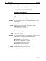
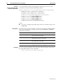
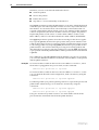
show classifier
SHow CLASSifier[={rule-id|ALL}]
Description
If a classifier specifies dhcpsnooping for the source MAC address or source IP
address, this is displayed in the command output, as shown in the following
example.
Figure 7: Example output from the show classifier command
Classifier Rules
-----------------------------------------------------------Rule .................. 1
D-MAC Address ........ ANY
S-MAC Address ........ ANY
M-Type ............... ANY
S-VLAN ............... ANY
E-Format ............. ANY
Protocol ............. IP
TPID ................. ANY
VLAN Priority ........ ANY
S-IP Address ......... DHCPSNOOPING
D-IP Address ......... ANY
IP Protocol .......... ANY
TOS/DSCP ............. ANY
------------------------------------------------------------
Software Version 2.7.6
C613-10462-00 REV A
24
DHCP Snooping
Release Note
show dhcpsnooping
Syntax
Description
SHow DHCPSnooping
This command displays the current DHCP snooping configuration (Figure 8,
Table 1).
Figure 8: Example output from the show dhcpsnooping command
DHCP Snooping Information
-----------------------------------------DHCP Snooping ................ Enabled
Option 82 status ........... Disabled
ARP security ............... Disabled
Debug enabled .............. None
DHCP Snooping Database:
Full Leases/Max Leases ..... 1/52
Check Interval ............. 60 seconds
------------------------------------------
Table 1: Parameters in output of the show dhcpsnooping command
Parameter
Meaning
DHCP Snooping
Whether DHCP snooping is enabled or disabled.
Option 82 status
Whether DHCP Option 82 is enabled or disabled for DHCP
snooping.
ARP security
Whether DHCP snooping ARP security is enabled or disabled
for untrusted ports.
Debug enabled
A list of the debug options that have been enabled for DHCP
snooping.
DHCP Snooping Database Section
DHCP snooping binding database related information.
Full Leases/Max Leases
The number of valid snooped leases, followed by the maximum
number of leases allowed on the switch.
Check interval
The DHCP snooping database check interval. This shows how
frequently the switch deletes expired entries.
Software Version 2.7.6
C613-10462-00 REV A
Software Version 2.7.6
25
show dhcpsnooping counter
Syntax
Description
SHow DHCPSnooping COUnter
This command displays current DHCP snooping counter information
(Figure 9, Table 2).
Figure 9: Example output from the show dhcpsnooping counter command
DHCP Snooping Counters
-----------------------------------------------------------DHCP Snooping
InPackets ...................... 1412
InBootpRequests ................ 725
InBootpReplies ................. 687
InDiscards ..................... 3
ARP Security
InPackets .......................
InDiscards ......................
NoLease .......................
Invalid........................
262
0
0
0
Table 2: Parameters in output of the show dhcpsnooping counters command
Parameter
Meaning
DHCP Snooping section
Counters related to DHCP packets processed by DHCP snooping.
InPackets
The total number of packets processed by DHCP snooping.
InBootpRequests
The number of BOOTP request packets processed by DHCP
snooping.
InBootpReplies
The number of BOOTP reply packets processed by DHCP
snooping.
InDiscards
The number of packets dropped by DHCP snooping.
ARP Security section
Counters related to ARP packets processed by DHCP snooping ARP security.
Software Version 2.7.6
C613-10462-00 REV A
InPackets
The total number of ARP packets processed by ARP security.
InDiscards
The total number of ARP packets discarded by ARP security.
NoLease
The number of ARP packets discarded by ARP security because
there was no DHCP lease on the port.
Invalid
The number of ARP packets discarded by ARP security because
their format was invalid.
26
DHCP Snooping
Release Note
show dhcpsnooping database
Syntax
Description
SHow DHCPSnooping DATABase
This command displays the information currently stored in the DHCP
snooping database (Figure 10, Table 3).
Figure 10: Example output from the show dhcpsnooping database command
DHCP Snooping Binding Database
-----------------------------------------Full Leases/Max Leases ... 3/52
Check Interval ........... 60 seconds
Database Listeners ....... CLASSIFIER
Current valid entries
MAC Address
IP Address
Expires(s) VLAN Port
ID
Source
------------------------------------------------------------------------------00-00-cd-08-0c-2c 192.168.12.110
566
46
15
2
Dynamic
00-00-cd-08-0d-de 192.168.12.111
1023
46
16
3
Dynamic
00-00-cd-09-43-22 192.168.12.210
Static
46
12
4
User
------------------------------------------------------------------------------Entries with client lease but no listeners
MAC Address
IP Address
Expires(s) VLAN Port
ID
Source
------------------------------------------------------------------------------None...
------------------------------------------------------------------------------Entries with no client lease and no listeners
MAC Address
IP Address
Expires(s) VLAN Port
ID
Source
------------------------------------------------------------------------------00-00-cd-08-1d-de 192.168.12.112
3511
46
15
4
Dynamic
Table 3: Parameters in output of the show dhcpsnooping database command
Parameter
Meaning
Full Leases/Max Leases
The number of valid snooped leases, followed by the maximum
number of leases allowed on the switch.
Check interval
The DHCP snooping database check interval. This shows how
frequently the switch deletes expired entries.
Database listeners
A list of processes within the switch that make use of the
binding database information. Currently, the Classifier module
is supported.
Current valid entries
This section lists the current snooped DHCP leases on the
specified ports, ordered by ascending MAC address. Entries in
this section indicate that the Classifier listening module has
been updated successfully. Dynamic sourced entries in this
section indicate that a DHCP ACK packet was forwarded to the
client. The expires parameter indicates the time in seconds
until the lease is set to expire.
Entries with client lease but This section lists the current snooped DHCP leases where a
no listeners
DHCP ACK packet was forwarded to the client, but a valid lease
could not be established due to an error with the Classifier
listening module.
This can occur if DHCP snooping is disabled while there are
current valid entries in the DHCP snooping database, and DHCP
snooping is then reconfigured and re-enabled.
Software Version 2.7.6
C613-10462-00 REV A
Software Version 2.7.6
27
Table 3: Parameters in output of the show dhcpsnooping database command (cont.)
Parameter
Meaning
Entries with no client lease This section lists DHCP snooped leases that have no valid
and no listeners
listener (the Classifier module), and for which the DHCP ACK
was not forwarded to the client. This can occur if there is an
error in the DHCP information.
When the DHCP ACK is not forwarded to the client, the client
continues to request a DHCP lease. For this reason, entries in
this section are added with an expires time of 3600 seconds,
regardless of the lease time contained in the DHCP ACK
packet.
Software Version 2.7.6
C613-10462-00 REV A
MAC Address
The client MAC address.
IP Address
The allocated client IP address.
Expires
The time in seconds before an entry expires.
VLAN
The VLAN that the lease is associated with.
PORT
The port that the lease is associated with.
ID
The DHCP snooping allocated ID number for this entry.
Source
The source of the DHCP snooping entry. “Dynamic” indicates
that the switch added the entry as a result of snooping a DHCP
IP allocation. “User” indicates that the user added the entry
statically. “File” indicates that the switch added the entry from
the bindings.dsn file when DHCP snooping was enabled.
28
DHCP Snooping
Release Note
show dhcpsnooping filter
Syntax
Description
SHow DHCPSnooping FILter[=ALL]
This command displays the current DHCP snooping filter information
(Figure 11, Table 4).
If all is specified, all DHCP snooping filter entries are shown, even if they are
currently unallocated. If all is not specified, only allocated entries are
displayed.
Figure 11: Example output from the show dhcpsnooping filter command
DHCPSnooping ACL ( 1 entries )
ClassID
FlowID
Port
EntryID
IP Address/Port/Mac
-------------------------------------------------------------------------------45521
1
1
1
192.168.11.19/1/00-00-cd-21-7c-fc
Table 4: Parameters in output of the show dhcpsnooping filter command
Parameter
Meaning
ClassID
Internally allocated classifier ID.
FlowID
• For AT-8600, AT-8700XL, Rapier, and AT-8800
Always 0.
• For AT-8900 and AT-9900
The QoS flow group ID that the filter entry is associated
with.
Port
The switch port number.
EntryID
The ID of the DHCP snooping database entry that generated
the filter entry.
IP Address/Port/MAC
The allocated IP address, switch port number, and client MAC
address.
Software Version 2.7.6
C613-10462-00 REV A
Software Version 2.7.6
29
show dhcpsnooping port
Syntax
SHow DHCPSnooping POrt[={port-list|ALL}]
where:
■
Description
port-list is a port number, range (specified as n-m), or comma-separated list
of numbers and/or ranges. Port numbers start at 1 and end at m, where m
is the highest numbered Ethernet switch port.
This command displays information about DHCP snooping for the specified
ports (Figure 12, Table 5).
Figure 12: Example output from the show dhcpsnooping port command
DHCP Snooping Port Information:
-----------------------------------------------------------Port ....................... 1
Trusted .................. Yes
Full Leases/Max Leases ... 0/0
Subscriber-ID ............
Port ....................... 2
Trusted .................. No
Full Leases/Max Leases ... 0/1
Subscriber-ID ............
Port .......................
Trusted ..................
Full Leases/Max Leases ...
Subscriber-ID ............
3
No
1/1
UserID 14424
Table 5: Parameters in output of the show dhcpsnooping port command
Software Version 2.7.6
C613-10462-00 REV A
Parameter
Meaning
Port
The number of the switch port.
Trusted
The DHCP snooping trusted state of the port, either Yes or No.
Full Leases/Max Leases
The number of valid snooped leases on the port, followed by
the maximum number of leases allowed on the port.
Subscriber-ID
The user allocated subscriber-ID that is added into the DHCP
Option 82 field when DHCP snooping Option 82 is enabled.
30
Deleting Dynamic ARP Entries
Release Note
Deleting Dynamic ARP Entries
Address Resolution Protocol (ARP) is used by the router or switch to
dynamically learn the location of devices in its networks. When the router or
switch receives a packet with an unknown destination address, it broadcasts an
ARP request to determine where to send that packet. When a host replies and
identifies itself as the destination for that address, the router or switch records
this information in a dynamic ARP entry in its ARP cache. It uses that ARP
entry to forward further packets to that address. Such dynamic ARP entries age
out if there is no traffic to that address for (by default) 17-34 minutes. This
removes entries for disconnected devices and devices that change their IP
addresses.
If you swap a device in your network for another device that has the same IP
address, the router or switch may be left with a stale ARP entry and be unable
to forward packets to the new device. This is most likely if you swap in the
device without taking the link to the router or switch down, for example, if it
connects through a hub. Instead of waiting for such entries to time out, you can
delete them.
Previous software versions allow you to delete individual ARP entries.
Software Version 2.7.6 also lets you delete all dynamic entries in a single step.
This is particularly useful if you do not know the relevant IP addresses.
The router or switch replaces the deleted ARP entries when it receives traffic
for the relevant addresses. As long as the entries are relearnt quickly enough,
deleting dynamic ARP entries does not affect:
■
routes
■
OSPF neighbour status
■
BGP peer status
■
the TCP/UDP connection status
■
VRRP status
To delete a single dynamic or static entry, use the command:
delete ip arp=ipadd
To delete all dynamic ARP entries, use the new alldynamic option in the
command:
delete ip arp=alldynamic
The alldynamic option does not delete static (manually-entered) ARP entries.
The router or switch generates a log message to record that dynamic ARP
entries have been deleted.
Command Change Summary
The following table summarises the modified commands (see Command
Reference Updates).
Command
Change
delete ip arp
New alldynamic option
Software Version 2.7.6
C613-10462-00 REV A
Software Version 2.7.6
31
Command Reference Updates
This section describes any new commands and the changed portions of any
modified commands and output screens. It uses boldface to highlight new
parameters and options of existing commands, and new fields of existing
output.
delete ip arp
Syntax
DELete IP ARP={ipadd|ALLDynamic}
where ipadd is an IP address in dotted decimal notation
Description
Software Version 2.7.6
C613-10462-00 REV A
The new alldynamic option deletes all dynamic ARP entries in the router or
switch’s ARP cache.
32
Redistributing BGP Routes into RIP
Release Note
Redistributing BGP Routes into RIP
Software Release 2.7.6 enables you to configure RIP to redistribute BGP routes.
You can redistribute up to 500 BGP routes as RIP routes, by using the
command:
add ip rip redistribute protocol=bgp [limit=1..500]
[metric=0..16] [routemap=routemap]
[subnet={on|off|yes|no|true|false}]
This command enables you to set the RIP metric for the imported routes,
choose whether to import subnet routes, specify the number of routes to
import, and filter routes through a route map.
To change the settings for redistributing routes, use the command:
set ip rip redistribute protocol=bgp [limit=1..500]
[metric=0..16] [routemap=routemap]
[subnet={on|off|yes|no|true|false}]
To display the settings for redistributing BGP routes, and the number of BGP
routes that RIP is currently redistributing, use the command:
show ip rip redistribute
To stop RIP from redistributing BGP routes, use the command:
delete ip rip redistribute protocol=bgp
The number of routes that RIP can redistribute is limited because RIP is not
designed to process large numbers of routes. By default, the limit is set to 50.
When the limit is reached, routes are no longer imported until existing routes
are removed. Because they are BGP routes, BGP controls when the routes
disappear. To ensure RIP imports the routes it needs to, we recommend you:
■
minimise the number of routes in the BGP route table by configuring
automatic summarising
■
use a route map to select an appropriate subset of the BGP routes, as
described in the next section
Filtering BGP Routes When Redistributing
To select the most appropriate routes for importing into BGP, you can apply a
route map, using one of the commands:
add ip rip redistribute protocol=bgp [routemap=routemap]
[other-options...]
set ip rip redistribute protocol=bgp [routemap=routemap]
[other-options...]
The router or switch can use the route map to:
■
accept or reject update messages on the basis of origin, community, AS
path, next hop or Multi Exit Discriminator (MED)
■
accept or reject particular routes, by comparing the update message’s
routes with a prefix list
■
alter matching routes’ metric and tag
Software Version 2.7.6
C613-10462-00 REV A
Software Version 2.7.6
33
Creating Route Maps
A route map consists of multiple entries, which are in effect individual filters.
Each entry specifies both what it matches on, in a match clause, and what is
done to matching traffic, in the entry’s action and any set clauses it has.
The set clauses modify the characteristics of matching routes. If you want to
change the characteristics of all candidate routes, configure an entry with no
match clause. Such an entry matches all routes.
When RIP passes a BGP-sourced route through a route map:
1.
It checks the entries in order, starting with the lowest numbered entry, until
it finds a match.
2.
It then takes the action specified by that entry’s action parameter. If the
action is exclude, it filters out that route. If the action is include, it filters in
that route.
3.
If the action is include, it modifies characteristics as specified by the entry’s
set clauses if there are any.
4.
It then stops processing that route; it does not check the remaining entries
in the route map.
Every route map ends with an implicit entry that matches all routes, with an
action of include. This ensures that if no entries in a route map generate a
match, the route is included without modification.
Creating a
route map
Configuring a match
clause
You do not have to create a route map as a separate step—adding the first entry
automatically creates it.
The match clause for a route map entry determines which routes match the
entry. A route map for use when importing BGP routes into RIP can match on
any of the available BGP attributes, or can match a list of prefixes.
For the available match clause options, and details of how to create each match
option, see the Filtering IP Routes chapter of the Software Reference.
Configuring a set
clause
Once you have determined which routes a route map entry matches, you can
configure set clauses to change the attributes of matching items.
To create a set clause for an entry, use one of the commands in the following
table.
Software Version 2.7.6
C613-10462-00 REV A
Command
Result
add ip routemap=routemap entry=1..4294967295
set metric=0..4294967295
Sets the RIP metric of matching
routes. Routes with a lower metric
are preferred. Metrics higher than
16 are treated as 16. Note that if
you set the metric using the
commands add ip rip
redistribute or set ip rip
redistribute, that metric
overrides the route map’s value.
add ip routemap=routemap entry=1..4294967295
set tag=1..65535
Tags the matching routes with an
ID number. This lets you later
identify the routes that came from
BGP.
34
Redistributing BGP Routes into RIP
Release Note
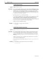
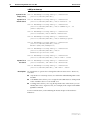
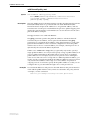
Overview of Filtering for RIP Routes
When the router or switch runs RIP, it receives routing information from
neighbouring routers, and can advertise RIP, BGP, statically-configured and
interface routes to neighbouring routers. You can filter routing information at
the processing points shown in the following figure.
RIP
RIP
neighbour
neighbours
incoming RIP
outgoing RIP
filtered by list of IP route filters
exporting
turned on with
filtered by route map
applied using
set ospf rip
add rip interface redistribute
interface
and
static routes
OSPF routes
BGP routes
Routing Information Base (RIB)
The filtering router or switch
ip-route-filter-rip
For more information, see the Filtering IP Routes chapter of the Software
Reference.
Command Change Summary
The following table summarises the modified commands (see Command
Reference Updates).
Command
Change
add ip rip redistribute
New command
delete ip rip redistribute
New command
set ip rip redistribute
New command
add ip routemap
A subset of existing parameters are valid when
importing BGP routes into RIP. Also, the metric
parameter can now specify a RIP metric
set ip routemap
A subset of existing parameters are valid when
importing BGP routes into RIP. Also, the metric
parameter can now specify a RIP metric
Software Version 2.7.6
C613-10462-00 REV A
Software Version 2.7.6
35
Command Reference Updates
This section describes any new commands and the changed portions of any
modified commands and output screens. It uses boldface to highlight new
parameters and options of existing commands, and new fields of existing
output.
add ip rip redistribute
Syntax
ADD IP RIP REDistribute PROTocol=BGP [LIMit=1..500]
[METric=0..16] [ROUTEMap=routemap]
[SUBNET={ON|OFF|YES|NO|True|False}]
where routemap is a character string from 1 to 15 characters long
Description
This command enables the router or switch to redistribute BGP routes as RIP
routes.
The protocol parameter specifies the routing protocol from which RIP will
obtain the routes that it redistributes. Protocol must be set to BGP. You can also
redistribute statically-configured routes into RIP by using the staticexport
parameter of the add ip rip interface command.
The limit parameter specifies the maximum number of BGP routes that the
router or switch can import into RIP. Importing too many routes into RIP
reduces RIP’s performance. The default limit is 50.
The metric parameter specifies the metric that RIP gives the imported routes.
Note that if you set the metric with this parameter and in a route map, this
parameter's value applies. If you do not specify a metric here or in a route map,
RIP uses the route’s original metric, or 16 if the metric is higher than 16.
The routemap parameter specifies a route map. You can use the route map to
select routes for RIP to import, and to tag routes or change the route metric.
The route map must already exist. To create a route map, use the add ip
routemap command on page 38.
The subnet parameter specifies whether RIP can import subnet routes. This
parameter only applies if the router or switch is configured to send RIP version
2 packets. If you specify no, RIP only imports classful network routes. If you
specify yes, RIP imports both classful and classless network routes. The default
is yes.
Example
To enable RIP to redistribute 50 BGP routes, which are selected by the route
map called bgp_to_rip, use the command:
add ip rip red prot=bgp routem=bgp_to_rip
Software Version 2.7.6
C613-10462-00 REV A
36
Redistributing BGP Routes into RIP
Release Note
delete ip rip redistribute
Syntax
Description
Example
DELete IP RIP REDistribute PROTocol=BGP
This command stops RIP redistributing BGP routes, by deleting the
redistribution entry.
To stop RIP from importing BGP routes, use the command:
del ip rip red prot=bgp
set ip rip redistribute
Syntax
SET IP RIP REDistribute PROTocol=BGP [LIMit=1..500]
[METric=0..16] [ROUTEMap=[routemap]]
[SUBNET={ON|OFF|YES|NO|TRUE|FALSE}]
where routemap is a character string from 1 to 15 characters long
Description
This command changes the settings the router or switch uses when it
redistributes BGP routes as RIP routes.
The protocol parameter specifies the routing protocol from which RIP will
obtain the routes that it redistributes. Protocol must be set to BGP. You can also
redistribute statically-configured routes into RIP by using the staticexport
parameter of the add ip rip interface command.
The limit parameter specifies the maximum number of BGP routes that the
router or switch can import into RIP. Importing too many routes into RIP
reduces RIP’s performance. The default limit is 50.
The metric parameter specifies the metric that RIP gives the imported routes.
Note that if you set the metric with this parameter and in a route map, this
parameter’s value applies. To stop setting the metric, enter metric= without
specifying a value. RIP then uses the route’s original metric, or 16 if the metric
is higher than 16.
The routemap parameter specifies a route map. You can use the route map to
select routes for RIP to import, and to tag routes or change the route metric.
The route map must already exist. To create a route map, use the add ip
routemap command on page 38. To stop using a route map, specify routemap=
without specifying a route map name.
The subnet parameter specifies whether RIP can import subnet routes. This
parameter only applies if the router or switch is configured to send RIP version
2 packets. If you specify off, RIP only imports classful network routes. If you
specify on, RIP imports classless network routes. The default is on.
Example
To change the number of routes that RIP imports to 200, use the command:
set ip rip red prot=bgp lim=200
Software Version 2.7.6
C613-10462-00 REV A
Software Version 2.7.6
37
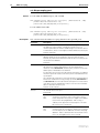
show ip rip redistribute
Syntax
Description
SHow IP RIP REDistribute
This command displays information about importing routes from BGP into RIP
(Figure 13, Table 6).
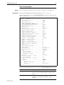
Figure 13: Example output from the show ip rip redistribute command
RIP Route Redistribute
Protocol
RouteMap
Subnet
Metric
Redistribute/Limit
----------------------------------------------------------BGP
bgp_to_rip Yes
10
68/100
-----------------------------------------------------------
Table 6: Parameters in output of the show ip rip redistribute command
Examples
Parameter
Meaning
Protocol
The routing protocol that the redistributed routes come
from: BGP.
RouteMap
The name of the route map that selects routes for RIP to
import, and/or changes the route metric.
Subnet
Whether RIP can import subnet routes; one of No (RIP only
imports classful network routes) or Yes (RIP imports classless
and classful network routes).
Metric
The metric RIP gives the imported routes, or “-” if the metric
is not changed when redistributing. Note that a metric set
by the route map overrides this setting.
Redistribute
The number of routes that RIP has redistributed.
Limit
The maximum number of routes that RIP can redistribute.
To display the number of BGP routes that RIP has redistributed, use the
command:
sh ip rip red
Software Version 2.7.6
C613-10462-00 REV A
38
Redistributing BGP Routes into RIP
Release Note
add ip routemap
Syntax for an
empty entry
ADD IP ROUTEMap=routemap ENTry=1..4294967295
[ACtion={INCLude|EXCLude}]
Syntax for a
match clause
ADD IP ROUTEMap=routemap ENTry=1..4294967295
[ACtion={INCLude|EXCLude}] MAtch ASPath=1..99
ADD IP ROUTEMap=routemap ENTry=1..4294967295
[ACtion={INCLude|EXCLude}] MAtch COMmunity=1..99
[EXAct={NO|YES}]
ADD IP ROUTEMap=routemap ENTry=1..4294967295
[ACtion=INCLude] MAtch MED=0..4294967295
ADD IP ROUTEMap=routemap ENTry=1..4294967295
[ACtion={INCLude|EXCLude}] MAtch NEXThop=ipadd
ADD IP ROUTEMap=routemap ENTry=1..4294967295
[ACtion={INCLude|EXCLude}] MAtch
ORIGin={EGP|IGP|INCOmplete}
ADD IP ROUTEMap=routemap ENTry=1..4294967295
[ACtion={INCLude|EXCLude}] MAtch
PREFIXList=prefixlist-name
ADD IP ROUTEMap=routemap ENTry=1..4294967295
[ACtion={INCLude|EXCLude}] MAtch TAG=1..65535
Syntax for a
set clause
ADD IP ROUTEMap=routemap ENTry=1..4294967295
[ACtion=INCLude] SET METric=0..4294967295
ADD IP ROUTEMap=routemap ENTry=1..4294967295
[ACtion={INCLude|EXCLude}] SET TAG=1..65535
Description
No parameters or options have changed in Software Version 2.7.6. However,
note that:
■
only the above route map clauses are valid when redistributing BGP routes
into RIP
■
a set metric clause allows you to assign the same RIP metric to all imported
routes. Numbers above 16 are treated as 16
■
a set tag clause allows you to tag all imported routes. This means you can
identify the route’s original source, for example, in the output of the show
ip route command
For more information, see the Filtering IP Routes chapter of the Software
Reference.
Software Version 2.7.6
C613-10462-00 REV A
Software Version 2.7.6
39
set ip routemap
Syntax for an
empty entry
SET IP ROUTEMap=routemap ENTry=1..4294967295
[ACtion={INCLude|EXCLude}]
Syntax for a
match clause
SET IP ROUTEMap=routemap ENTry=1..4294967295
[ACtion={INCLude|EXCLude}] MAtch ASPath=1..99
SET IP ROUTEMap=routemap ENTry=1..4294967295
[ACtion={INCLude|EXCLude}] MAtch COMmunity=1..99
[EXAct={NO|YES}]
SET IP ROUTEMap=routemap ENTry=1..4294967295
[ACtion=INCLude] MAtch MED=0..4294967295
SET IP ROUTEMap=routemap ENTry=1..4294967295
[ACtion={INCLude|EXCLude}] MAtch NEXThop=ipadd
SET IP ROUTEMap=routemap ENTry=1..4294967295
[ACtion={INCLude|EXCLude}] MAtch
ORIGin={EGP|IGP|INCOmplete}
SET IP ROUTEMap=routemap ENTry=1..4294967295
[ACtion={INCLude|EXCLude}] MAtch
PREFIXList=prefixlist-name
SET IP ROUTEMap=routemap ENTry=1..4294967295
[ACtion={INCLude|EXCLude}] MAtch TAG=1..65535
Syntax for a
set clause
SET IP ROUTEMap=routemap ENTry=1..4294967295
[ACtion=INCLude] SET METric=0..4294967295
SET IP ROUTEMap=routemap ENTry=1..4294967295
[ACtion={INCLude|EXCLude}] SET TAG=1..65535
Description
No parameters or options have changed in Software Version 2.7.6. However,
note that:
■
only the above route map clauses are valid when redistributing BGP routes
into RIP
■
a set metric clause allows you to assign the same RIP metric to all imported
routes. Numbers above 16 are treated as 16
■
a set tag clause allows you to tag all imported routes. This means you can
identify the route’s original source, for example, in the output of the show
ip route command
For more information, see the Filtering IP Routes chapter of the Software
Reference.
Software Version 2.7.6
C613-10462-00 REV A
40
Classifying On Layer 4 Port Range
Release Note
Classifying On Layer 4 Port Range
Software Version 2.7.6 makes it easy to create a classifier that matches a range
of source or destination TCP or UDP ports. In previous software versions, you
could specify a port range by entering a port number and a mask. With
Software Version 2.7.6, you can simply enter the first and last numbers in the
range, separated by a hyphen. To do this, use one of the commands:
create classifier=rule-id [tcpsport={portid|port-range|any}]
[tcpdport={portid|port-range|any}]
[udpsport={portid|port-range|any}]
[udpdport={portid|port-range|any}] [other-options...]
set classifier=rule-id [tcpsport={portid|port-range|any}]
[tcpdport={portid|port-range|any}]
[udpsport={portid|port-range|any}]
[udpdport={portid|port-range|any}] [other-options...]
where port-range is a hyphen-separated range of TCP/IP or UDP/IP ports,
such as 5550-5554.
The following table describes the Layer 4 port parameters.
When...
The classifier matches all packets whose...
TCPSport=port-range
source TCP port is in this range.
TCPDport=port-range
destination TCP port is in this range.
UDPSport=port-range
source UDP port is in this range.
UDPDport=port-range
destination UDP port is in this range.
The existing functionality, which allows you to specify a port number and
mask, is still supported.
Command Change Summary
The following table summarises the modified commands (see Command
Reference Updates).
Command
Change
create classifier
New port-range option on the Layer 4 port
parameters.
set classifier
New port-range option on the Layer 4 port
parameters.
show classifier
If a classifier specifies a range, the range is
displayed in the command output.
Software Version 2.7.6
C613-10462-00 REV A
Software Version 2.7.6
41
Command Reference Updates
This section describes any new commands and the changed portions of any
modified commands and output screens. It uses boldface to highlight new
parameters and options of existing commands, and new fields of existing
output.
create classifier
Syntax:
non-IPv6 traffic
For non-IPv6 traffic:
CREate CLASSifier=rule-id
[MACSaddr={macadd|ANY}] [MACDaddr={macadd|ANY}]
[MACType={L2Ucast|L2Mcast|L2Bcast|ANY}] [TPID=tpid|ANY]
[VLANPriority=0..7|ANY] [VLAN={vlanname|1..4094|ANY}]
[INNERTpid=tpid|ANY] [INNERVLANPriority=0..7|ANY]
[INNERVLANId=VLAN=1..4094|ANY]
[ETHFormat={802.2-Tagged|802.2-Untagged|ETHII-Tagged|
ETHII-Untagged|NETWARERAW-Tagged|Netwareraw-untagged|
SNAP-Tagged|SNAP-Untagged|ANY}]
[PROTocol={protocoltype|IP|IPX|ANY}]
[IPDScp={dscplist|ANY}] [IPTOs={0..7|ANY}]
[IPSAddr={ipaddmask|ANY}] [IPDAddr={ipaddmask|ANY}]
[IPPRotocol={TCP|UDP|ICMp|IGMp|ipprotocolnum|ANY}]
[IPXDAddr={ipxadd|ANY}]
[IPXDSocket={NCP|SAP|RIP|NNB|DIAg|NLSp|IPXwan|
ipxsocketnum|ANY}]
[IPXSSocket={NCP|SAP|RIP|NNB|DIAg|NLSp|IPXwan|
ipxsocketnum|ANY}]
[TCPSport={portid|port-range|ANY}]
[TCPDport={portid|port-range|ANY}]
[UDPSport={portid|port-range|ANY}]
[UDPDport={portid|port-range|ANY}]
[L4SMask=mask|ANY] [L4DMask=mask|ANY]
[L5BYTE01=byteoffset,bytevalue[,bytemask]]
[L5BYTE02=byteoffset,bytevalue[,bytemask]]
[L5BYTE03=byteoffset,bytevalue[,bytemask]]
[L5BYTE04=byteoffset,bytevalue[,bytemask]]
[L5BYTE05=byteoffset,bytevalue[,bytemask]]
[L5BYTE06=byteoffset,bytevalue[,bytemask]]
[L5BYTE07=byteoffset,bytevalue[,bytemask]]
[L5BYTE08=byteoffset,bytevalue[,bytemask]]
[L5BYTE09=byteoffset,bytevalue[,bytemask]]
[L5BYTE10=byteoffset,bytevalue[,bytemask]]
[L5BYTE11=byteoffset,bytevalue[,bytemask]]
[L5BYTE12=byteoffset,bytevalue[,bytemask]]
[L5BYTE13=byteoffset,bytevalue[,bytemask]]
[L5BYTE14=byteoffset,bytevalue[,bytemask]]
[L5BYTE15=byteoffset,bytevalue[,bytemask]]
[L5BYTE16=byteoffset,bytevalue[,bytemask]]
Software Version 2.7.6
C613-10462-00 REV A
42
Classifying On Layer 4 Port Range
Syntax:
accelerated IPv6 traffic
at Layer 3 processor
Release Note
For accelerated IPv6 traffic, when applied on the Layer 3 processor of the
accelerator on AT-8948 and AT-9924T/4SP switches:
CREate CLASSifier=rule-id [ETHFormat={ETHII-Tagged|ANY}]
[PROTocol=IPV6] [IPDScp={0..63|ANY}]
[IPSAddr={ipv6-add/prefix-length|ANY}]
[IPDAddr={ipv6-add/prefix-length|ANY}]
[IPPRotocol={TCP|UDP|ICMp|ipprotocolnum|ANY}]
[TCPSport={portid|port-range|ANY}]
[TCPDport={portid|port-range|ANY}]
[UDPSport={portid|port-range|ANY}]
[UDPDport={portid|port-range|ANY}]
[L4SMask=mask|ANY] [L4DMask=mask|ANY]
where:
■
Description
Example
port-range is a hyphen-separated range of TCP/IP or UDP/IP ports, such
as 5550-5554.
The new port-range option specifies a range of Layer 4 ports for the parameters
in the following table. If you specify a port range, the l4smask or l4dmask
parameters are invalid.
Parameter
Description
TCPSport=port-range
Source TCP port: the classifier matches all packets with a
source TCP port in this range.
TCPDport=port-range
Destination TCP port: the classifier matches all packets with
a destination TCP port in this range.
UDPSport=port-range
Source UDP port: the classifier matches all packets with a
source UDP port in this range.
UDPDport=port-range
Destination UDP port: the classifier matches all packets with
a destination UDP port in this range.
To create classifier 10 which selects all packets with a destination TCP port in
the range 5550 to 5554, use the command:
create classifier=10 tcpdport=5550-5554
Software Version 2.7.6
C613-10462-00 REV A
Software Version 2.7.6
43
set classifier
Syntax:
non-IPv6 traffic
For non-IPv6 traffic:
SET CLASSifier=rule-id
[MACSaddr={macadd|ANY}] [MACDaddr={macadd|ANY}]
[MACType={L2Ucast|L2Mcast|L2Bcast|ANY}] [TPID=tpid|ANY]
[VLANPriority=0..7|ANY] [VLAN={vlanname|1..4094|ANY}]
[INNERTpid=tpid|ANY] [INNERVLANPriority=0..7|ANY]
[INNERVLANId=VLAN=1..4094|ANY]
[ETHFormat={802.2-Tagged|802.2-Untagged|ETHII-Tagged|
ETHII-Untagged|NETWARERAW-Tagged|Netwareraw-untagged|
SNAP-Tagged|SNAP-Untagged|ANY}]
[PROTocol={protocoltype|IP|IPX|ANY}]
[IPDScp={dscplist|ANY}] [IPTOs={0..7|ANY}]
[IPSAddr={ipaddmask|ANY}] [IPDAddr={ipaddmask|ANY}]
[IPPRotocol={TCP|UDP|ICMp|IGMp|ipprotocolnum|ANY}]
[IPXDAddr={ipxadd|ANY}]
[IPXDSocket={NCP|SAP|RIP|NNB|DIAg|NLSp|IPXwan|
ipxsocketnum|ANY}]
[IPXSSocket={NCP|SAP|RIP|NNB|DIAg|NLSp|IPXwan|
ipxsocketnum|ANY}]
[TCPSport={portid|port-range|ANY}]
[TCPDport={portid|port-range|ANY}]
[UDPSport={portid|port-range|ANY}]
[UDPDport={portid|port-range|ANY}]
[L4SMask=mask|ANY] [L4DMask=mask|ANY]
[L5BYTE01=byteoffset,bytevalue[,bytemask]]
[L5BYTE02=byteoffset,bytevalue[,bytemask]]
[L5BYTE03=byteoffset,bytevalue[,bytemask]]
[L5BYTE04=byteoffset,bytevalue[,bytemask]]
[L5BYTE05=byteoffset,bytevalue[,bytemask]]
[L5BYTE06=byteoffset,bytevalue[,bytemask]]
[L5BYTE07=byteoffset,bytevalue[,bytemask]]
[L5BYTE08=byteoffset,bytevalue[,bytemask]]
[L5BYTE09=byteoffset,bytevalue[,bytemask]]
[L5BYTE10=byteoffset,bytevalue[,bytemask]]
[L5BYTE11=byteoffset,bytevalue[,bytemask]]
[L5BYTE12=byteoffset,bytevalue[,bytemask]]
[L5BYTE13=byteoffset,bytevalue[,bytemask]]
[L5BYTE14=byteoffset,bytevalue[,bytemask]]
[L5BYTE15=byteoffset,bytevalue[,bytemask]]
[L5BYTE16=byteoffset,bytevalue[,bytemask]]
Software Version 2.7.6
C613-10462-00 REV A
44
Classifying On Layer 4 Port Range
Syntax:
accelerated IPv6 traffic
at Layer 3 processor
Release Note
For accelerated IPv6 traffic, when applied on the Layer 3 processor of the
accelerator on AT-8948 and AT-9924T/4SP switches:
SET CLASSifier=rule-id [ETHFormat={ETHII-Tagged|ANY}]
[PROTocol=IPV6] [IPDScp={0..63|ANY}]
[IPSAddr={ipv6-add/prefix-length|ANY}]
[IPDAddr={ipv6-add/prefix-length|ANY}]
[IPPRotocol={TCP|UDP|ICMp|ipprotocolnum|ANY}]
[TCPSport={portid|port-range|ANY}]
[TCPDport={portid|port-range|ANY}]
[UDPSport={portid|port-range|ANY}]
[UDPDport={portid|port-range|ANY}]
[L4SMask=mask|ANY] [L4DMask=mask|ANY]
where:
■
Description
port-range is a hyphen-separated range of TCP/IP or UDP/IP ports, such
as 5550-5554.
The new port-range option specifies a range of Layer 4 ports for the parameters
in the following table. If you specify a port range, the l4smask or l4dmask
parameters are invalid.
Parameter
Description
TCPSport=port-range
Source TCP port: the classifier matches all packets with a
source TCP port in this range.
TCPDport=port-range
Destination TCP port: the classifier matches all packets with
a destination TCP port in this range.
UDPSport=port-range
Source UDP port: the classifier matches all packets with a
source UDP port in this range.
UDPDport=port-range
Destination UDP port: the classifier matches all packets with
a destination UDP port in this range.
Software Version 2.7.6
C613-10462-00 REV A
Software Version 2.7.6
45
show classifier
SHow CLASSifier[={rule-id|ALL}]
Description
If a classifier specifies a range, the range is displayed in the command output,
as shown in the following example.
Figure 14: Example output from the show classifier command
Classifier Rules
-----------------------------------------------------------Rule .................. 10
D-MAC Address ........ ANY
S-MAC Address ........ ANY
M-Type ............... ANY
S-VLAN ............... ANY
E-Format ............. ANY
Protocol ............. IP
TPID ................. ANY
VLAN Priority ........ ANY
S-IP Address ......... ANY
D-IP Address ......... ANY
IP Protocol .......... TCP
TOS/DSCP ............. ANY
S-TCP Port ........... ANY
D-TCP Port range ..... 5550-5554
------------------------------------------------------------
Software Version 2.7.6
C613-10462-00 REV A
46
Firewall Enhancements
Release Note
Firewall Enhancements
Software Version 2.7.6 includes the following enhancements to the firewall:
■
Session Monitoring
■
Enhanced Network Address and Port Translation (ENAPT)
This section describes each enhancement, then the new and modified
commands in Command Reference Updates.
Session Monitoring
Firewall session monitoring enables the firewall to copy all traffic that goes to
and from specified IP addresses and send the copies to a packet capturing
device. You can choose whether to copy packets before or after the firewall has
processed them, or both. Session monitoring is useful:
■
as an advanced diagnostic tool to check firewall configuration. By
capturing packets on both the public and private sides of the firewall, you
can compare packets before and after firewall processing. This enables you
to check the effect of features such as NAT.
■
if you need to monitor the traffic that passes through the firewall to or from
certain hosts.
The following figure demonstrates monitoring of traffic to and from a single
host on a LAN.
Internet
Firewall
L2 switch
Packet
capturing
device
LAN
Monitored
device
fw-monitor
Monitoring only copies packets that pass through the firewall. It does not copy
packets that the firewall blocks.
Software Version 2.7.6
C613-10462-00 REV A
Software Version 2.7.6
47
Configuring Session Monitoring
Monitoring is disabled by default. To configure it, you need to set up a packet
capturing device to collect the packet copies, create a monitor, and enable
monitoring. The following table lists the commands to use on the router or
switch.
Step Command
Action
1
—
Connect a device to capture the copies,
such as a PC running packet capturing
software, to an Eth port or a switch port.
1
create vlan=vlan-name vid=vid
Configure the interface to which you
connected the packet capturing device:
add vlan=vlan-name port=port-number
[other-options...]
add ip interface={ethx|vlanx} ip=ipadd
[other-options...]
2
add firewall monitor=monitor-id
ip=ipadd copyto=ip-interface
[applyto={private|public|both}]
• If you connected it to a switch port,
put the port in a separate VLAN.
• Give the Eth port or VLAN an IP
address.
Create a monitor. Specify:
• the IP address of the device you
want to monitor
• the interface to which you
connected the capturing device,
using the copyto parameter.
• optionally, whether to monitor the
private interface, the public
interface, or both. The default is the
private interface.
3
enable firewall monitor
Enable session monitoring.
4
show firewall monitor
Check the monitor configuration.
Effect of deleting
interfaces
If a monitor is configured to send duplicated packets to an interface (the copyto
interface) and you delete that interface, then the firewall deactivates that
monitor. If you add the interface again, the firewall automatically reactivates
the monitor.
Effect on firewall
throughput
The firewall’s throughput is affected by on how much traffic it monitors at
once. For example, if the firewall monitors all the traffic that passes through it
at a given time, it processes packets approximately half as fast as if it monitors
no traffic.
Software Version 2.7.6
C613-10462-00 REV A
48
Firewall Enhancements
Multiple monitors
Release Note
There is no limit on the number of devices you can monitor, although you
should consider the performance impact of monitoring a high proportion of
traffic.
The firewall determines which monitor to use on traffic by checking the
monitor’s IP address against all IP address fields for the session. These session
fields appear in the output of the show firewall session command, and are
summarised in the following table.
Duplicate monitors
IP field name in session
Meaning
IP
The source address of outbound packets and the
destination address of inbound packets in this session,
as seen on the private side of the firewall.
Remote IP
The destination address of outbound packets and the
source address of inbound packets in this session, as
seen on the private side of the firewall.
Gbl IP
The source address of outbound packets and the
destination address of inbound packets in this session,
as seen on the public side of the firewall. If NAT is not
configured, this is the same as IP.
Gbl Remote IP
The destination address of outbound packets and the
source address of inbound packets in this session, as
seen on the public side of the firewall. If NAT is not
configured, this is the same as Remote IP.
If two monitors monitor different addresses that are part of the same session,
and both monitors apply on the same side of the firewall, then the firewall uses
the last-created monitor. This avoids unnecessary packet duplication. For
example, consider the scenario in the following diagram, in which NAT on the
firewall translates between a private IP address (192.168.1.1, the IP entry in
output from the show firewall session command) and a public IP address
(192.0.2.1, the Gbl IP entry).
Internet
public
address:
Gbl IP
192.0.2.1
NAT
Firewall
private
address:
IP
192.168.1.1
fw-mon-conflict
To monitor traffic in this scenario, you can apply a monitor to the private
interface that specifies either the private address 192.168.1.1 or the public
address 192.0.2.1. However, it is possible to create Monitor 1 that monitors the
private address and then Monitor 2 that monitors the public address, by using
the commands:
add firewall monitor=1 ip=192.168.1.1 copyto=vlan2
applyto=private
add firewall monitor=2 ip=192.0.2.1 copyto=vlan3
applyto=private
Both these monitors apply to sessions that match this scenario. The firewall
uses Monitor 2, because it was the last monitor to be created. This means that
copies of packets are sent to the copyto interface specified in Monitor 2, not the
interface specified in Monitor 1.
If you delete the second monitor, the first monitor takes over. If the deleted
monitor was monitoring a current session, monitoring may stop for a few
seconds.
Software Version 2.7.6
C613-10462-00 REV A
Software Version 2.7.6
49
Command Change Summary
The following table summarises the new commands (see Command Reference
Updates).
Software Version 2.7.6
C613-10462-00 REV A
Command
Change
enable firewall monitor
New command
disable firewall monitor
New command
add firewall monitor
New command
delete firewall monitor
New command
set firewall monitor
New command
show firewall monitor
New command
50
Firewall Enhancements
Release Note
Enhanced Network Address and Port Translation
(ENAPT)
Software Version 2.7.6 supports Enhanced Network Address and Port
Translation (ENAPT). With ENAPT, the firewall translates private IP addresses
and ports to a public IP address and ports. It remembers the private to public
mapping and applies the same mapping for all simultaneous sessions that
involve the same private IP address and port.
ENAPT is a port restricted cone NAT, as defined in RFC 3489, STUN - Simple
Traversal of User Datagram Protocol (UDP) Through Network Address Translators
(NATs).
ENAPT combines:
When to use ENAPT
■
Enhanced NAT’s ability to translate many private addresses to one public
address
■
NAPT’s ability to avoid changes to the UDP or TCP port number
ENAPT enables the firewall to work with applications in which a private
device may initiate sessions with multiple external servers or hosts. One such
application is Xbox Live ®, as shown in the following figure.
Xbox Live
player B
5
3 4
Internet
1
2
Xbox Live
player A
Xbox
server
firewall
fw-enapt-xbox
In the above figure, Xbox Live player A is behind the firewall which is
performing ENAPT. Before playing, player A registers with the Xbox Live
server (step 1) and the server replies (step 2). Likewise, player B registers with
the server (steps 3 and 4). When the players wish to start a game with each
other, the server tells each Xbox the public IP address and port of the other
Xbox, and they establish a session between them (step 5). Player A’s Xbox must
use the same public IP address and port when communicating with the server
and with player B, or player B cannot connect to player A.
ENAPT deletes the private to public mapping when the last session that uses
that mapping closes. This has no effect when using it with Xbox Live, because
the first session is initiated by the private device, but makes ENAPT less
suitable than NAPT for use with VoIP systems.
Software Version 2.7.6
C613-10462-00 REV A
Software Version 2.7.6
Creating an ENAPT:
interface-based
51
To add an interface-based ENAPT to a policy, use the new nat=enapt option in
the add firewall policy nat command:
add firewall policy=policy-name nat=enapt interface=interface
gblinterface=interface [gblip=ipadd[-ipadd]]
ENAPT translates packets’ private IP addresses to one of the following public
addresses:
■
the address specified by the gblip parameter, if you specify a single IP
address
■
the lowest address in the range of addresses specified by the gblip
parameter, if you specify a range.
■
the IP address of the public interface, if you do not specify gblip. This is
useful if the address of the public interface is dynamically-assigned and
therefore changes.
ENAPT also translates a private port (such as 3074 for Xbox gaming) to a public
port. The firewall randomly allocates the public port and remembers the
private to public mapping. If you want to apply ENAPT to a particular private
port, create a rule-based ENAPT instead of an interface-based ENAPT. If you
need to control the private and public port, create a rule-based NAPT instead
of using ENAPT.
Creating an ENAPT:
rule-based
To add a rule-based ENAPT to a policy, use the new nattype=enapt option in
the add firewall policy rule command:
add firewall policy=policy-name rule=rule-id action=nat
nattype=enapt interface=private-interface
protocol={protocol|all|egp|gre|icmp|ospf|sa|tcp|udp}
gblip=ipadd [ip=ipadd[-ipadd]] [port=port]
[sourceport=port]
[other-options-to-match-packets]
For more information about the IP address and port parameters that are valid
with ENAPT rules, and the translations, see “IP and port parameters in policy
rules” on page 56.
You can create a rule that only applies to Xbox Live traffic by specifying the
TCP/UDP port. All Xbox Live traffic has a source port of 3074. Traffic to the
Xbox Live server also has a destination port of 3074, but the destination port of
other Xboxes may vary. Therefore, to limit the rule to Xbox Live traffic, specify
the source port by using sourceport=3074.
Increasing ICMP
unreachable timeout
If you are configuring the firewall to allow Xbox Live sessions, also increase the
ICMP unreachable message timeout. The timeout specifies the delay before the
firewall deletes a session after it receives an ICMP unreachable message for
that session. If you do not increase it, you may be unable to connect to remote
Xboxes that are also behind a firewall. A suitable timeout is approximately 20
seconds. To set it, use the command:
set firewall policy=policy-name
icmpunreachabletimeout=seconds [other-options]
Software Version 2.7.6
C613-10462-00 REV A
52
Firewall Enhancements
Release Note
Command Change Summary
The following table summarises the modified commands (see Command
Reference Updates).
Command
Change
add firewall policy nat
New enapt option for nat parameter
add firewall policy rule
New enapt option for nattype parameter
set firewall policy
New icmpunreachabletimeout parameter
show firewall
The ICMP unreachable timeout is displayed.
If a policy uses ENAPT, “enapt” is displayed in
the NAT field.
show firewall policy
The ICMP unreachable timeout is displayed.
If a policy uses ENAPT, “enapt” is displayed in
the NAT field.
Software Version 2.7.6
C613-10462-00 REV A
Software Version 2.7.6
53
Command Reference Updates
This section describes any new commands and the changed portions of any
modified commands and output screens. It uses boldface to highlight new
parameters and options of existing commands, and new fields of existing
output.
add firewall monitor
Syntax
ADD FIREwall MOnitor=monitor-id IP=ipadd
COPyto=ip-interface [APPlyto={PRIVate|PUBlic|BOTH}]
where:
Description
■
monitor-id is an integer from 1 to 65535
■
ipadd is an IPv4 address in dotted decimal notation
■
ip-interface is a VLAN or Eth interface such as vlan2 or eth0. The interface
can be a logical interface such as vlan2-1 or eth0-1
This command specifies an IP address for the firewall to monitor. The firewall
makes a copy of every packet that comes from and goes to that address. It
sends the copy over the Eth interface or VLAN that you specify.
There is no limit on the number of IP addresses you can monitor, although you
should consider the speed impact of monitoring a high proportion of traffic.
Caution: If you create two or more monitors that monitor a given firewall
session on the same firewall applyto interface, the firewall only uses the
last-created monitor.
The monitor parameter specifies an identification number for the monitor.
The ip parameter specifies the IP address of the monitored device. The firewall
monitors any firewall sessions that have this IP address in any of the session
fields. These session fields display in output from the show firewall session
command, and are summarised in the following table.
Software Version 2.7.6
C613-10462-00 REV A
IP field name in session
Meaning
IP
The source address of outbound packets and the
destination address of inbound packets in this session, as
seen on the private side of the firewall.
Remote IP
The destination address of outbound packets and the
source address of inbound packets in this session, as seen
on the private side of the firewall.
Gbl IP
The source address of outbound packets and the
destination address of inbound packets in this session, as
seen on the public side of the firewall. If NAT is not
configured, this is the same as IP.
Gbl Remote IP
The destination address of outbound packets and the
source address of inbound packets in this session, as seen
on the public side of the firewall. If NAT is not configured,
this is the same as Remote IP.
54
Firewall Enhancements
Release Note
Therefore, sessions are monitored whether the device:
■
sends the packets
■
receives the packets
■
initiates the session
■
responds to a session initiated by another device
The copyto parameter specifies the Eth interface or VLAN to which the firewall
sends the copies of monitored packets. Packets are sent as Layer 2 broadcasts to
this interface. You should connect a device directly to this interface that can
correctly capture the broadcast packets, such as a PC running packet capturing
software. In particular, the device should not forward or reply to the packets.
Duplicated packets use the router or switch’s MAC address as their source
MAC address, and have a broadcast destination MAC address (ff:ff:ff:ff:ff:ff).
The applyto parameter specifies where the monitoring for this device applies.
If you specify private, the firewall copies packets at the private interface. This
is before firewall processing for outgoing packets and after firewall processing
for incoming packets. If you specify public, the firewall copies packets at the
public interface. This is before firewall processing for incoming packets and
after firewall processing for outgoing packets. If you specify both, the firewall
copies packets at both the public interface and the private interface. The default
is private.
The combination of ip and applyto uniquely identifies a monitor. For example,
you can create different monitors to monitor the same IP address on the private
and the public interfaces.
Example
To monitor traffic to and from the host whose IP address is 192.168.1.1, when
the monitor is plugged into the port in vlan2, use the command:
add fire mo=1 ip=192.168.1.1 cop=vlan2
To monitor traffic to and from the host whose IP address is 192.168.1.1 so that
you can check the firewall’s NAT configuration, make a monitor by using the
command:
add fire mo=1 ip=192.168.1.1 cop=vlan2 app=both
Use filtering within your packet capturing software to separate the private and
public traffic. Alternatively, you can make two monitors by using the
commands:
add fire mo=1 ip=192.168.1.1 cop=vlan2 app=priv
add fire mo=2 ip=192.168.1.1 cop=vlan3 app=pub
Using two monitors may make it easier to see which traffic came from the
private interface and which came from the public interface.
Software Version 2.7.6
C613-10462-00 REV A
Software Version 2.7.6
55
add firewall policy nat
Syntax
Description
ADD FIREwall POLIcy=policy-name
NAT={ENAPt|ENHanced|STAndard} INTerface=interface
[IP=ipadd[-ipadd]] GBLINterface=interface
[GBLIP=ipadd[-ipadd]]
The new enapt option for the nat parameter specifies that the firewall performs
Enhanced NAPT, which is a port restricted cone NAT. With ENAPT, the
firewall translates all private IP addresses to one global IP address, and also
translates TCP or UDP ports. It remembers the private to public mapping and
applies the same mapping for all simultaneous sessions that involve the same
private IP address and port.
The ip parameter is not valid with ENAPT.
The gblip parameter specifies the public IP address to which the firewall
translates the private address, and is optional with ENAPT. If the gblip
parameter is not specified, the IP address of the global interface is used as the
global IP internet address. This is useful in configurations where the public
interface does not have a static IP address, for example, a dial-up user who is
dynamically allocated an IP address by the ISP.
If nat is set to enhanced or enapt, then you generally only need to specify a
single global IP address. You only need to specify a range of public addresses if
sessions will be initiated from the public side to private hosts via multiple
public addresses. For example, if you have two private servers offering the
same service and each server corresponds to a different public IP address, you
need to specify a range that includes both public IP addresses. However, NAT
only uses the first address of the range as a source address for packets in
outgoing sessions. You need to specify all the public addresses so that you can
configure rules to pass the traffic through to the correct private host.
Example
To translate IP addresses and ports for all traffic between the private interface
vlan2 and the public interface vlan3, which are attached to the policy named
“example”, use the command:
add fire poli=example nat=enap int=vlan2 gblin=vlan3
Software Version 2.7.6
C613-10462-00 REV A
56
Firewall Enhancements
Release Note
add firewall policy rule
Syntax
Description
IP and port parameters
in policy rules
ADD FIREwall POLIcy=policy-name RUle=rule-id
ACtion={ALLOw|DENY|NAT|NONat} INTerface=interface
PROTocol={protocol|ALL|EGP|GRE|ICmp|OSPF|SA|TCP|UDP}
[AFTer=hh:mm] [BEFore=hh:mm]
[DAYs={ALL|MON|TUE|WED|THU|FRI|SAT|SUN|WEEKDay|WEEKEnd}
[,...]] [ENCapsulation={NONE|IPSec}] [GBLIP=ipadd]
[GBLPort={ALL|port[-port]|service-name}]
[GBLRemoteip=ipadd[-ipadd]] [IP=ipadd[-ipadd]]
[LISt={list-name|RADius|MACRADius}]
[NATType={DOuble|ENAPt|ENHanced|NApt|REVerse|STAndard}]
[NATMask=ipadd] [POrt={ALL|port[-port]|service-name}]
[REMoteip=ipadd[-ipadd]] [SOurceport={ALL|port[-port]}]
[TTL=hh:mm]
The new enapt option for the nattype parameter specifies that the firewall
performs Enhanced NAPT on traffic that matches the rule.
The following table shows the IP address and port parameters that you can use
when you create a rule to apply ENAPT to matching traffic. It indicates which
parameters the rule can match against to select packets, and which parameters
specify translations. The table also indicates whether the rule matches source
or destination IP address or port. For example, when the private interface
processes an outgoing packet for a session that the private side initiated, ip is
the packet’s source address and remoteip is its destination address.
Rule-based
NAT type
Interface
Type of address
or port
Match
Translate to
ENAPT
Private:
outgoing
traffic
Source IP
ip
glbip
(nattype=
enapt)
(required)
Destination IP
remoteip
Not translated
Source TCP/UDP
port
sourceport
Translated; no
user control
Destination
TCP/UDP port
port
Not translated
The following table shows the IP address and port parameters that you can use
when you create a rule on a policy that uses interface-based ENAPT. It
indicates which parameters the rule can match against to select packets, and
which parameters specify translations. In this situation, the rule specifies
whether to allow or deny the traffic, and what the IP address and port are
translated to. The ENAPT is defined by using the add firewall policy nat
command, but the rule translations override the interface-based translations.
Interface-based Interface
NAT type
Type of address
or port
Match
Translate to
ENAPT
Destination IP
glbip
ip
(required)
(required)
Source IP
remoteip
Not translated
Destination
TCP/UDP port
gblport
port
(required)
(required)
Source
TCP/UDP port
sourceport
Not translated
Public:
incoming
traffic
destined for a
private server
etc
Software Version 2.7.6
C613-10462-00 REV A
Software Version 2.7.6
Example
57
In this example, the host with private IP address 192.168.1.1 wishes to play
Xbox Live, through the firewall policy called “zone1”, over the private
interface vlan1. The router’s public IP address is 192.0.2.1. You want to limit the
rule so that it only translates Xbox Live traffic, which has a source port of 3074.
To configure this, use the commands:
add fire poli=zone1 ru=1 ac=nat natt=enap int=vlan1 prot=udp
ip=192.168.1.1 gblip=192.0.2.1 so=3074
add fire poli=zone1 ru=2 ac=nat natt=enap int=vlan1 prot=tcp
ip=192.168.1.1 gblip=192.0.2.1 so=3074
delete firewall monitor
Syntax
DELete FIREwall MOnitor=monitor-id
where:
■
monitor-id is an integer from 1 to 65535
Description
This command deletes a monitor. The firewall stops copying packets that come
to and from the IP address specified in that monitor.
Example
To stop monitoring the host with IP address 192.168.1.1, which is monitored by
Monitor 1, use the command:
del fire mo=1
disable firewall monitor
Syntax
Description
Example
DISable FIREwall MOnitor
This command stops the firewall from monitoring traffic. Monitoring is
disabled by default.
To stop the firewall from monitoring any hosts, use the command:
dis fire mo
enable firewall monitor
Syntax
Description
ENAble FIREwall MOnitor
This command enables the firewall to monitor traffic. When you enable
monitoring and specify the IP addresses of devices to monitor, the router or
switch makes a copy of all packets that go to or from those devices. To specify
devices to monitor, use the add firewall monitor command on page 53.
Monitoring is disabled by default.
Example
To allow the firewall to start monitoring devices, use the command:
ena fire mo
Software Version 2.7.6
C613-10462-00 REV A
58
Firewall Enhancements
Release Note
set firewall monitor
Syntax
SET FIREwall MOnitor=monitor-id [IP=ipadd]
[COPyto=ip-interface] [APPlyto={PRIVate|PUBlic|BOTH}]
where:
Description
■
monitor-id is an integer from 1 to 65535
■
ipadd is an IPv4 address in dotted decimal notation
■
ip-interface is a VLAN or Eth interface such as vlan2 or eth0. The interface
can be a logical interface such as vlan2-1 or eth0-1
This command modifies a session monitor.
Note that modifying the monitor does not reset its counters.
The monitor parameter specifies the identification number for the monitor.
The ip parameter specifies the IP address of the monitored device. The firewall
monitors any firewall sessions that have this IP address in any of the session
fields. These session fields display in output from the show firewall session
command, and are summarised in the following table.
IP field name in session
Meaning
IP
The source address of outbound packets and the
destination address of inbound packets in this session, as
seen on the private side of the firewall.
Remote IP
The destination address of outbound packets and the
source address of inbound packets in this session, as seen
on the private side of the firewall.
Gbl IP
The source address of outbound packets and the
destination address of inbound packets in this session, as
seen on the public side of the firewall. If NAT is not
configured, this is the same as IP.
Gbl Remote IP
The destination address of outbound packets and the
source address of inbound packets in this session, as seen
on the public side of the firewall. If NAT is not configured,
this is the same as Remote IP.
Therefore, sessions are monitored whether the device:
■
sends the packets
■
receives the packets
■
initiates the session
■
responds to a session initiated by another device
The copyto parameter specifies the Eth interface or VLAN to which the firewall
sends the copies of monitored packets. Packets are sent as Layer 2 broadcasts to
this interface. You should connect a device directly to this interface that can
correctly capture the broadcast packets, such as a PC running packet capturing
software. In particular, the device should not forward or reply to the packets.
Duplicated packets use the router or switch’s MAC address as their source
MAC address, and have a broadcast destination MAC address (ff:ff:ff:ff:ff:ff).
Software Version 2.7.6
C613-10462-00 REV A
Software Version 2.7.6
59
The applyto parameter specifies where the monitoring for this device applies.
If you specify private, the firewall copies packets at the private interface. This
is before firewall processing for outgoing packets and after firewall processing
for incoming packets. If you specify public, the firewall copies packets at the
public interface. This is before firewall processing for incoming packets and
after firewall processing for outgoing packets. If you specify both, the firewall
copies packets at both the public interface and the private interface. The default
is private.
The combination of ip and applyto uniquely identifies a monitor. For example,
you can create different monitors to monitor the same IP address on the private
and the public interfaces.
Example
To change Monitor 1 so that it sends copied packets out over vlan3, use the
command:
add fire mo=1 cop=vlan3
set firewall policy
Syntax
SET FIREwall POLIcy=policy-name
[ICMPUnreachabletimeout=seconds]
[MACCachetimeout=max-age] [MAXUPNPPORTMAPS={0..1000}]
[OTHERTimeout=minutes] [RADIuslimit=number
[TCPTimeout=minutes] [UDPTimeout=minutes]
[UPNP={ON|OFF|YES|NO|ENABLED|DISABLED}]
where seconds is an integer from 0 to 65535
Description
The new icmpunreachabletimeout parameter specifies the delay before the
firewall deletes a session after it receives an ICMP unreachable message for
that session. The default is 0 seconds, which means the firewall deletes the
associated session immediately.
If you are configuring the firewall to allow Xbox Live sessions, increase this
timeout to a few seconds, for example, 20. Otherwise you may be unable to
connect to remote Xboxes that are also behind a firewall.
Software Version 2.7.6
C613-10462-00 REV A
60
Firewall Enhancements
Release Note
show firewall
Syntax
Description
SHow FIREwall
This command displays firewall settings, including a summary of each policy
(Figure 15, Table 7).
Figure 15: Example output from the show firewall command for a policy that uses
interface-based ENAPT
Firewall Configuration
Status .................... disabled
Enabled Notify Options .... manager
SIP ALG enabled ........... FALSE
Maximum Packet Fragments .. 20
Policy : example
TCP Timeout (s) ...................
UDP Timeout (s) ...................
Other Timeout (s) .................
ICMP Unreachable Timeout (s) ......
TCP Handshake Timeout Mode ........
SMTP Domain .......................
TCP Setup Proxy ...................
UPNP ..............................
WAN interfaces ..................
LAN interfaces ..................
Maximum port maps ...............
SIP ALG ...........................
Private Interface : vlan2
Public Interface : vlan3
Method ..........................
NAT .............................
Method ........................
Private Interface .............
Global IP .....................
3600
1200
1200
0
Normal
not set
enabled
disabled
none
none
250
disabled
dynamic
enapt
vlan2
192.168.2.3
Table 7: New and changed parameters in output of the show firewall command
Parameter
Meaning
ICMP Unreachable Timeout
The number of seconds before the firewall deletes a session
after it receives an ICMP unreachable message for that
session.
NAT
The type of network address translation that the policy
performs. If the policy performs ENAPT, “enapt” is
displayed.
Software Version 2.7.6
C613-10462-00 REV A
Software Version 2.7.6
61
show firewall policy
Syntax
Description
SHow FIREwall POLIcy[=policy-name] [COUnter] [SUMmary]
This command displays firewall policy settings (Figure 16, Table 8).
Figure 16: Example output from the show firewall policy command for a policy that uses
interface-based ENAPT
Policy : example
TCP Timeout (s) ...................
UDP Timeout (s) ...................
Other Timeout (s) .................
ICMP Unreachable Timeout (s) ......
TCP Handshake Timeout Mode ........
MAC Cache Timeout (m) .............
RADIUS Limit ......................
Accounting ........................
Enabled Logging Options ...........
Enabled Debug Options .............
Enabled Debug Modes ...............
Enabled Debug IP Address ..........
Identification Protocol Proxy .....
Enabled IP options ................
Enhanced Fragment Handling ........
Enabled ICMP forwarding ...........
Receive of ICMP PINGS .............
Number of Notifications ...........
Number of Deny Events .............
Number of Allow Events ............
Number of Active TCP Opens ........
Number of Active Sessions .........
Cache Hits ........................
Discarded ICMP Packets ............
SMTP Domain .......................
FTP Data Port .....................
TCP Setup Proxy ...................
UPNP ..............................
WAN interfaces ..................
LAN interfaces ..................
Maximum port maps ...............
SIP ALG ...........................
Private Interface : vlan2
Trust Private ...................
Public Interface : vlan3
Method ..........................
NAT .............................
Method ........................
Private Interface .............
Global IP .....................
3600
1200
1200
0
Normal
1440
100
disabled
none
none
none
none
enabled
none
none
none
enabled
0
0
0
0
0
0
0
not set
RFC enforced
enabled
disabled
none
none
250
disabled
yes
dynamic
enapt
vlan2
192.168.2.3
Table 8: New and changed parameters in output of the show firewall policy command
Software Version 2.7.6
C613-10462-00 REV A
Parameter
Meaning
ICMP Unreachable Timeout
The number of seconds before the firewall deletes a session
after it receives an ICMP unreachable message for that
session.
NAT
The type of network address translation that the policy
performs. If the policy performs ENAPT, “enapt” is
displayed.
62
Firewall Enhancements
Release Note
show firewall monitor
Syntax
Description
SHow FIREwall MOnitor
This command displays information about session monitoring (Figure 17,
Table 9).
Figure 17: Example output from the show firewall monitor command
Firewall Monitoring
Status .................... enabled
Monitor IP
Apply to
Copy to
In(pkts)
Out(pkts)
-------------------------------------------------------------------------------1
192.168.1.1
PRIVATE
VLAN2
0
0
2
192.168.1.2
PRIVATE
VLAN2
24
26
--------------------------------------------------------------------------------
Table 9: Parameters in output of the show firewall monitor command
Example
Parameter
Meaning
Status
Whether firewall session monitoring is enabled or disabled.
Monitor
The identification number of each monitor. This number uniquely
identifies the monitored device.
IP
The IP address of the monitored device. The firewall copies all traffic that
comes to or from this address.
Copy to
The interface to which the firewall transmits copies of packets; one of a
VLAN, an Eth interface, or “deleted” if the interface has been deleted.
Deleting the interface deactivates the monitor. Adding the interface back
again reactivates the monitor.
Apply to
The firewall interface on which the firewall captures packets; one of
PRIVATE, PUBLIC, or BOTH. PRIVATE means that packets are copied
before firewall processing for outgoing packets and after firewall
processing for incoming packets. PUBLIC means that packets are copied
before firewall processing for incoming packets and after firewall
processing for outgoing packets.
In
The number of incoming packets that the firewall has captured using this
monitor. The counter resets when the router or switch restarts.
Out
The number of outgoing packets that the firewall has captured using this
monitor. The counter resets when the router or switch restarts.
To display the number of packets that the firewall has copied, use the
command:
sh fire mo
Software Version 2.7.6
C613-10462-00 REV A
Software Version 2.7.6
63
Reverse Telnet Without Authentication
Reverse Telnet allows you to connect a device such as a modem to an
asynchronous port, and then to control that device by telneting from your PC
to the router or switch. Reverse Telnet is described in RFC 2217, Telnet Com Port
Control Option. The router or switch listens on a TCP port, and the TCP listen
port number depends on the asyn port number (excluding asyn0), according to
the following formula:
TCP port number = 2000 + asyn port number
For example:
■
the reverse Telnet connection for connection to asyn1 uses the TCP port
number 2001
■
the reverse Telnet connection for connection to asyn5 uses the TCP port
number 2005. Asyn5 would be the first port of the second asynchronous
PIC on the router or switch, when two PICs are plugged into bay 1.
The Telnet connection to the router or switch is authenticated, so when you use
reverse Telnet to access a remote device through the router or switch, you have
to enter a username and password. Some remote devices, such as other routers,
also require authentication. This can mean that you have to enter a username
and password twice. Software Version 2.7.6 simplifies this by allowing you to
establish the initial reverse Telnet connection to the router or switch without
authentication.
To stop reverse Telnet from requiring authentication of the Telnet session, use
the new command:
set rtelnet authentication=off
To see if authentication is turned off, use the command:
show config dynamic=telnet
Command Change Summary
The following table summarises the new command (see Command Reference
Updates).
Software Version 2.7.6
C613-10462-00 REV A
Command
Change
set rtelnet
New command
64
Reverse Telnet Without Authentication
Release Note
Command Reference Updates
This section describes any new commands and the changed portions of any
modified commands and output screens. It uses boldface to highlight new
parameters and options of existing commands, and new fields of existing
output.
set rtelnet
Syntax
Description
SET RTELnet AUthentication={OFf|ON|NO|YEs|FAlse|TRue}
This command determines whether users who connect to an asynchronous
port through reverse Telnet must log in and be authenticated. If the device that
is connected to the asynchronous port also requires authentication, then
turning authentication off on the reverse Telnet connection stops users from
having to log in twice.
The authentication parameter specifies whether the router or switch
authenticates reverse Telnet connections. If you specify on, users must log in to
establish a reverse Telnet session. The router or switch only establishes the
session if the supplied username and password are valid. If you specify off,
users do not have to log in. The values on, yes and true are equivalent. The
values off, no and false are equivalent. The default is on.
Example
To establish reverse Telnet sessions without authenticating user information,
use the command:
set rtel au=of
Software Version 2.7.6
C613-10462-00 REV A