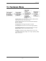
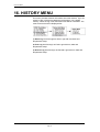
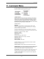
1
AutroFlame X33AF
Multi-spectrum IR flame detector
Addendum
Protecting life, environment and property...
116-P-X33AFADDENDUM/YGB, DEC P/N 95-8624, 2007-11-12
COPYRIGHT ©
This publication, or parts thereof, may not
be reproduced in any form, by any
method, for any purpose.
Autronica Fire and Security AS and its
subsidiaries assume no responsibility for
any errors that may appear in the
publication, or for damages arising from
the information in it. No information in this
publication should be regarded as a
warranty made by Autronica Fire and
Security. The information in this
publication may be updated without
notice.
Product names mentioned in this
publication may be a trademark. They are
used only for identification.
Table of Contents
Table of Contents
1. Introduction.......................................................................3
1.1
1.2
1.3
About this manual.............................................................................. 3
The reader......................................................................................... 3
Other reference documents .............................................................. 3
2. Interconnecting the communicator with the
detector
............................................................................4
3. HART Device Description Language...............................7
4. Detector Wiring .................................................................8
5. HART Menu Structure.......................................................9
6. X33AF Root Menu .............................................................10
7. Device Info Menu ..............................................................11
8. General Info Menu ............................................................12
9. HART Info Menu ................................................................13
10. HART PV Menu..................................................................14
11. Condensed Status ............................................................15
12. Status Info Menu ...............................................................16
13. Hardware Menu .................................................................17
14. Oi Menu ............................................................................18
15. Detector Settings ..............................................................19
16. HISTORY MENU ................................................................20
17. Command Menu ................................................................21
Addendum, AutroFlame X33AF 116-P-X33AFADDENDUM/YGB, DEC P/N 95-8624, 2007-11-12, Autronica Fire and Security AS
Page 1
Table of Contents
18. HART CMD Menu ..............................................................22
19. Device Setup Menu ...........................................................22
20. Configuration Menu ..........................................................23
21. Calibration Menu...............................................................23
22. Write Protect .....................................................................24
23. HART Setup .......................................................................25
24. Set Real Time Clock .........................................................25
25. Reader’s comments..........................................................27
Addendum, AutroFlame X33AF 116-P-X33AFADDENDUM/YGB, DEC P/N 95-8624, 2007-11-12, Autronica Fire and Security AS
Page 2
Introduction
1. Introduction
1.1 About this manual
This manual provides supplementay information for the AutroFlame
X33AF multispectrum IR flame detector.
Digital communication with the X33AF allows the operator to monitor
the status of the detector, determine factory settings, adjust field
settings, and initiate field tests. This addendum provides guidance for
establishing HART communication, and describes the HART menu
structure when using the X33AF with a HART Handheld
Communicator, a PC, or other process interface device that supports
DDL.
1.2 The reader
This handbook is intended for Autronica personnel authorized to
install the AutroFlame X33AF multispectrum IR flame detector.
NOTE
A minimum level of understanding with regard to the
operation and navigation of the HART Communicator is required.
1.3 Other reference documents
For further information about the AutroFlame X33AF multispectrum IR
flame detector, refer to the following:
Manual
Article no.
Datasheet
116-P-X33AF/CE
Handbook
116-P-X33AF/DE
Addendum, AutroFlame X33AF 116-P-X33AFADDENDUM/YGB, DEC P/N 95-8624, 2007-11-12, Autronica Fire and Security AS
Page 3
Interconnecting the communicator with the detector
2. Interconnecting the
communicator with the detector
Point-to-Point Mode
The HART Communicator can connect to the X33AF at any wiring
termination point in the analog output signal loop. Connect the HART
communicator in parallel with the X33AF analog signal or load
resistor. The HART connections are non-polarized
IMPORTANT WIRING NOTE
The HART Communicator does not measure loop current directly, but
instead reads a voltage signal across a resistance (250 ohms) in the
loop. The recommended connection point is across the input
impedance of the signal receiver (PLC), which is a nominal 250 ohms.
See Figures 1 to 4. If testing/programming on a bench, a 250 ohm
load resistor must be used. See Figure 5.
Switch on the HART Communicator. If a device is found, the HART
Communicator displays the Main menu. If no device is found, check
the connections and verify the presence of a minimum of 250 ohms
load resistance in series in the loop.
Addendum, AutroFlame X33AF 116-P-X33AFADDENDUM/YGB, DEC P/N 95-8624, 2007-11-12, Autronica Fire and Security AS
Page 4
Interconnecting the communicator with the detector
Figure 3—X33AF Detector Wired for Non-Isolated 4 to 20 mA
Current Output (Sinking)
Figure 1—X33AF Detector Wired for Non-Isolated 4 to 20 mA
Current Output (Sourcing)
Figure 4—X33AF Detector Wired for Isolated 4 to 20 mA
Current Output (Sinking)
Figure 2—X33AF Detector Wired for Isolated 4 to 20 mA
Current Output (Sourcing)
*Nominal input impedance of PLC = 250 ohms.
Maximum loop impedance including input impedance of PLC = 875 ohms.
Figure 5—Wiring the X33AF for Benchtop Testing/Programming
Using HART Protocol
Addendum, AutroFlame X33AF 116-P-X33AFADDENDUM/YGB, DEC P/N 95-8624, 2007-11-12, Autronica Fire and Security AS
Page 5
Interconnecting the communicator with the detector
Multidrop Mode
Optical flame detectors are life safety devices and require the 4-20
mA loop for transmitting important detector status data. They should
not be used in conjunction with multidrop mode. If multidrop mode is a
requirement, the alarm and fault relay contacts must be connected
directly to the safety system or fire panel for signalling purposes.
NOTE
This addendum covers HART wiring only. Refer to the device
instruction manual for NFPA-72 compliant releasing wiring diagrams.
Addendum, AutroFlame X33AF 116-P-X33AFADDENDUM/YGB, DEC P/N 95-8624, 2007-11-12, Autronica Fire and Security AS
Page 6
HART Device Description Language
3. HART Device Description
Language
The HART protocol incorporates a concept called the Device
Description Language (DDL) that enables all suppliers of HART
instruments to define and document their products in a single
consistent format. This format is readable by handheld
communicators, PCs and other process interface devices that support
DDL. DDL enables full interoperability of devices, regardless of
manufacturer, allowing full functionality from any HART device.
In the event that your Communicator does not establish
communications with the X33AF, ensure that the appropriate DDLs for
the X33AF have been programmed into your Communicator. To
review the DDLs programmed into your HART Communicator:
1. From the Main menu, access the Offline menu.
2. From the Offline menu, select New Configuration to
access the list of device descriptions programmed
into the HART Communicator.
3. Select Det-Tronics and review the list of models to
determine if the X33AF DDLs are installed in your
Communicator.
If the X33AF DDLs have not been programmed into the Memory
Module, you must use the generic interface built into your HART
Communicator.
The HART Communication Foundation manages a library of
Manufacturer Device Descriptions, which are distributed to
programming sites for inclusion in master devices. A complete listing
of the HCF DD Library is available for download in manufacturer and
device type sequence at www.ccsi.com/hart.
Addendum, AutroFlame X33AF 116-P-X33AFADDENDUM/YGB, DEC P/N 95-8624, 2007-11-12, Autronica Fire and Security AS
Page 7
Detector Wiring
4. Detector Wiring
Refer to the X33AF instruction manual for complete instructions
regarding detector installation and wiring. However, note that the
device power consumption specifications for the HART model are
different than the standard model.
Power Consumption Specifications of X33AF Detector with HART
Communication
Without heater: 4.7 watts at 24 vdc nominal;
6.1 watts at 24 vdc in alarm.
5.5 watts at 32 vdc nominal;
7.4 watts at 32 vdc in alarm.
Heater only: 8 watts maximum.
Total power: 17 watts at 32 vdc with EOL resistor installed
and heater on maximum.
EOL resistor must be ceramic, wirewound type, rated 5 watts
minimum, with actual power dissipation not to exceed 1.5 watts.
Addendum, AutroFlame X33AF 116-P-X33AFADDENDUM/YGB, DEC P/N 95-8624, 2007-11-12, Autronica Fire and Security AS
Page 8
HART Menu Structure
5. HART Menu Structure
Addendum, AutroFlame X33AF 116-P-X33AFADDENDUM/YGB, DEC P/N 95-8624, 2007-11-12, Autronica Fire and Security AS
Page 9
X33AF Root Menu
6. X33AF Root Menu
When HART communication is established, the first menu displayed is
the X33AF Root menu:
When HART communication is established, the first menu displayed is
the X33AF Root menu:
1) Fire (Yes/No) Indicates “Y” if the device is in a fire alarm status —
analog output is at 20 mA, fire alarm relay is actuated and LED is red.
2) Fault (Yes/No) Indicates “Y” if a fault condition exists. Go to
“Device Info” and select “Status Info” to determine the nature of the
fault.
3) Device Info Menu Provides access to manufacturer and HART
information, current device status, factory settings, and history logs.
4) Command Menu This menu allows the operator to initiate a
manual Oi test and also to perform various reset/clear functions.
5) Device Setup Menu This menu allows various setup, configuration
and calibration functions.
Addendum, AutroFlame X33AF 116-P-X33AFADDENDUM/YGB, DEC P/N 95-8624, 2007-11-12, Autronica Fire and Security AS
Page 10
Device Info Menu
7. Device Info Menu
This menu allows access to a variety of “read only” information.
1) General Info Menu Factory information.
2) HART Info Menu HART Specific Variables.
3) Status Info Menu Current operating status and/or diagnostic
information.
4) Detector Settings Factory settings relating to relay operation,
detector sensitivity and response.
5) History Menu Display log files: Alarm, Fault, General.
Addendum, AutroFlame X33AF 116-P-X33AFADDENDUM/YGB, DEC P/N 95-8624, 2007-11-12, Autronica Fire and Security AS
Page 11
General Info Menu
8. General Info Menu
1) Manufacturer Det-Tronics.
2) Model X3301.
3) Serial Number Serial number of device.
4) Part Number Manufacturer’s part number for this device.
5) Manufactured Date Date of manufacture shown as XX/XX/XX
(month/day/year).
6) Snsr Fmwr Ver Firmware revision level of sensor module.
7) HART Fmwr Ver Firmware revision level of HART Interface Board
(HIB).
8) Real Time Clock Current time and date settings of real time clock.
9) Write Protect (Y/N) This indicates whether variables can be written
to the device, or whether commands that cause actions to be
performed in the device can or cannot occur.
Addendum, AutroFlame X33AF 116-P-X33AFADDENDUM/YGB, DEC P/N 95-8624, 2007-11-12, Autronica Fire and Security AS
Page 12
HART Info Menu
9. HART Info Menu
1) Universal Rev HART universal revision.
2) Field Device Rev HART field device revision.
3) Final Asmbly No. A number that is used for identification
purposes, and is associated with the overall field device.
4) Tag Text that is associated with the field device installation. This
text can be used by the operator in any way.
5) Date Any date chosen by the operator to be used for any purpose.
6) Descriptor Text associated with the field device that can be used
by the operator in any way.
7) Message Text associated with the field device that can be used by
the operator in any way.
8) Num Req Preams HART specific synchronization messages.
9) HART PV Menu Display HART specific primary variable (PV)
items.
10) Condensed Status Device status condensed for HART handheld
display.
Addendum, AutroFlame X33AF 116-P-X33AFADDENDUM/YGB, DEC P/N 95-8624, 2007-11-12, Autronica Fire and Security AS
Page 13
HART PV Menu
10. HART PV Menu
1) PV Unit Not implemented for X33AF.
2) PV Not implemented for X33AF.
3) PV SNSR Unit Not implemented for X33AF.
4) PV USL Not implemented for X33AF.
5) PV LSL Not implemented for X33AF.
6) PV MIN SPAN Not implemented for X33AF.
7) PV DAMP Not implemented for X33AF.
8) PV AO Analog Output. The value that tracks the Digital Value
representation, under normal operating modes.
9) PV AO ALRM TYP Not implemented for X33AF.
10) PV % RNGE Percent of Range. The variable that tracks the Digital
Value representation with respect to the range defined by the Lower
Range Value and Upper Range Value, for normal operating modes.
The units of this variable are always in percent.
11) PV XFER FNCTN Not implemented for X33AF.
12) PV RNGE Unit Not implemented for X33AF.
13) PV URV Not implemented for X33AF.
14) PV LRV Not implemented for X33AF.
15) PV SNSR S/N Not implemented for X33AF.
Addendum, AutroFlame X33AF 116-P-X33AFADDENDUM/YGB, DEC P/N 95-8624, 2007-11-12, Autronica Fire and Security AS
Page 14
Condensed Status
11. Condensed Status
1) Xmtr Addstatus 0
Fire Alarm
Oi Cal Active
Manual Oi Active
Warmup
2) Xmtr Addstatus 1
Spare
3) Xmtr Addstatus 2
Fault
Auto Oi Fault
Manual Oi Fault
Oi Cal Fault
Dim Detect Fault (Diminished detection fault)
Detect Disable Flt (Detection disabled fault)
Temp Out of Range
Volt Out of Range (Operating voltage out of range)
4) Xmtr Addstatus 3
Snsr HW Fault (Sensor hardware fault)
HART HW Fault (HART hardware fault)
Intern Comm Fault (Modbus communication fault)
Incompatible Fault
5) Operating Mode
Fault
Fire Alarm
6) Operating Mode 2
Spare
Addendum, AutroFlame X33AF 116-P-X33AFADDENDUM/YGB, DEC P/N 95-8624, 2007-11-12, Autronica Fire and Security AS
Page 15
Status Info Menu
12. Status Info Menu
This menu (read only) shows extensive status information about the
detector.
1) Warmup (Y/N) Device is in the power-up time delay (warm-up)
mode.
2) Fire (Y/N) Indicates “Y” if the device is in a fire alarm status —
analog output is at 20 mA, fire alarm relay is actuated and LED is red.
3) Auto Oi Fault (Y/N) Automatic Oi Fault. Check viewing windows
and Oi reflector plate for cleanliness.
4) Dim Detect Fault (Y/N) Diminished Detection Fault. Excessive
background IR radiation. Eliminate IR interference and/or reaim/orient detector.
5) Detect Disable Flt (Y/N) Flame detector function has been
disabled. Check viewing windows for cleanliness and/or presence of
excessive background IR signal.
6) Snsr Hdwr Fault (Y/N) Sensor hardware fault.
7) HIB Hdwr Fault (Y/N) HART Interface Board hardware fault.
8) Int Comm Fault Internal communication fault.
9) Incompatible Flt Sensor module firmware version is not
compatible with HART Interface Board.
10) Voltage Fault (Y/N) Detector operating voltage is out of tolerance.
11) Hardware Menu Refer to sub-menu.
12) Oi Menu Refer to sub-menu.
Addendum, AutroFlame X33AF 116-P-X33AFADDENDUM/YGB, DEC P/N 95-8624, 2007-11-12, Autronica Fire and Security AS
Page 16
Hardware Menu
13. Hardware Menu
1) Heater Power Actual heater power (0 to 100%). Heater prevents
condensation and icing on the detector optics.
2) Heater Setpoint Maximum amount of heater power allowed (in
percent of full power).
3) Temperature Actual integral temperature of detector.
4) Temp Setpoint Temperature at which heater begins operating.
5) Temp Range Fault Detector integral temperature out of range —
Operating range: –40°F to +167°F (–40°C to +75°C).
6) Voltage Actual detector supply voltage (must be 18 to 32 Vdc).
7) Volt Range Fault Supply voltage is out of range. Operating voltage
must be 18 to 32 Vdc.
Addendum, AutroFlame X33AF 116-P-X33AFADDENDUM/YGB, DEC P/N 95-8624, 2007-11-12, Autronica Fire and Security AS
Page 17
Oi Menu
14. Oi Menu
1) Left Oi Percentage of calibrated Oi test signal returned by the left
sensor. Reading should be 90 to 100 percent. If reading is below 90
percent, go to “Device Setup”, select “Calibration”, and perform Oi
Calibration.
2) Middle Oi Percentage of calibrated Oi test signal returned by the
middle sensor. Reading should be 90 to 100 percent. If reading is
below 90 percent, go to “Device Setup”, select “Calibration”, and
perform Oi Calibration.
3) Right Oi Percentage of calibrated Oi test signal returned by the
right sensor. Reading should be 90 to 100 percent. If reading is below
90 percent, go to “Device Setup”, select “Calibration”, and perform Oi
Calibration.
4) Oi Fail Count Number of consecutive Oi failures counted (one
passed Oi test resets the counter).
5) No. Oi Failures Set (allowable) number of consecutive Oi failures
to produce a fault.
6) Oi Cal Active Oi calibration is in progress.
7) Oi Cal Fault An Oi calibration fault has occurred.
8) Manual Oi Active A manual Oi test is in progress.
9) Manual Oi Fail The detector has failed the last manual Oi test.
Addendum, AutroFlame X33AF 116-P-X33AFADDENDUM/YGB, DEC P/N 95-8624, 2007-11-12, Autronica Fire and Security AS
Page 18
Detector Settings
15. Detector Settings
This menu shows factory settings relating to relay operation, detector
sensitivity and response.
1) Fire Relay (L/NL) Fire relay contacts, latching (L) or non-latching
(NL).
2) Fire Relay (NDE/NE) Fire relay coil, normally de-energized (NDE)
or normally energized (NE).
3) Fault Relay (L/NL) Fault relay contacts, latching (L) or non-latching
(NL).
4) Fault Relay (NDE/NE) Fault relay coil, normally de-energized
(NDE) or normally energized (NE).
5) Aux Relay (L/NL) Auxiliary relay contacts, latching (L) or nonlatching (NL).
6) Aux Relay (NDE/NE) Auxiliary relay coil, normally de-energized
(NDE) or normally energized (NE).
7) Sensitivity (VH/H/M/L) Detector sensitivity setting: Very high, High,
Medium, or Low.
8) Response (.5/3/6/9) Fire alarm processing time in seconds.
Addendum, AutroFlame X33AF 116-P-X33AFADDENDUM/YGB, DEC P/N 95-8624, 2007-11-12, Autronica Fire and Security AS
Page 19
HISTORY MENU
16. HISTORY MENU
This menu provides historical information about the detector. Up to 32
events in each of the three categories will be kept in non-volatile
memory. When the log is full, the oldest event will be overwritten. The
most recent event will be displayed first.
1) Alarm Log Scroll through 32 Alarm Logs with time, date and
temperature stamp.
2) Fault Log Scroll through 32 Fault Logs with time, date and
temperature stamp.
3) General Log Scroll through 32 General Logs with time, date and
temperature stamp.
Addendum, AutroFlame X33AF 116-P-X33AFADDENDUM/YGB, DEC P/N 95-8624, 2007-11-12, Autronica Fire and Security AS
Page 20
Command Menu
17. Command Menu
The Command Menu allows the operator to initiate a manual Oi test
and also to perform various reset/clear functions.
1) Start Passive Oi
A passive Oi test command checks the cleanliness of the detector’s
optical surfaces. This confirms the ability of the detector to respond
correctly to an IR signal. Fire and fault relays as well as 4 to 20 mA
current loop output are unaffected by this test. A red LED signals a
successful test, and an amber LED signals a failed test. The event log
will indicate either “Man Oi Pass” or “Man Oi Flt”.
2) Start Active Oi
CAUTION
An active Oi test generates an actual Fire Alarm Output. All fire
response equipment must be bypassed/disabled prior to testing to
prevent unwanted output actuation.
An active Oi test performs an Oi test with all detector outputs fully
operational. Fire and fault relays as well as the 4-20mA loop are “live”.
If the test is successful: Fire relay = Alarm.
Fault relay = no fault.
Current output is 20 mA.
LED turns red.
General log indicates “Man Oi Pass”.
If the test is unsuccessful: Fire relay = No Alarm.
Fault relay = Fault.
Current output is 2 mA.
LED turns amber.
Fault log indicates “Man Oi Flt”.
3) Clear Oi Fault If the cause of the fault has not been corrected,
subsequent Oi faults will occur.
4) Reset Latches Latching relays are reset and LED turns green.
5) Master Reset This function re-initializes the microprocessor, resets
the operating software, and initiates a hardware reset for both the
sensor and the HART interface. Latched relays are reset.
6) Clear Data Log This function resets the HART data log history. To
view the logs, go to “Device Info Menu” and select “History Menu”.
7) HART Command Menu This menu performs various diagnostic
and/or service functions.
Addendum, AutroFlame X33AF 116-P-X33AFADDENDUM/YGB, DEC P/N 95-8624, 2007-11-12, Autronica Fire and Security AS
Page 21
HART CMD Menu
18. HART CMD Menu
The HART CMD (Command) Menu allows the operator to perform
diagnostic and service functions as follows:
1) Self Test Internal tests are performed and any detected problems
are reported in “Status Info”.
2) Master Reset This function re-initializes the microprocessor, resets
the operating software, and initiates a hardware reset for both the
sensor and the HART interface. Latched relays are reset.
3) Loop Test This test allows the operator to manually set the analog
signal output (4 to 20 mA) to a fixed user defined value.
19. Device Setup Menu
This menu allows various setup, configuration and calibration
functions. When Write Protect is off, these menus allow the operator
to reconfigure or write new variables to the device.
1) Configuration Menu
2) Calibration Menu
3) Write Protect
4) HART Setup
5) Set Real Time Clock
Refer to the appropriate sub-menus for details.
Addendum, AutroFlame X33AF 116-P-X33AFADDENDUM/YGB, DEC P/N 95-8624, 2007-11-12, Autronica Fire and Security AS
Page 22
Configuration Menu
20. Configuration Menu
1) Edit Cons Oi Fails This option allows the operator to select the
number of consecutive Oi failures before an Oi fault will be generated.
Selectable range is 1 to 1000.
2) Edit Temp Setpoint This option allows the operator to select the
temperature at which the optics heater begins operating.
3) Edit Heater Setpoint This option allows the operator to select the
maximum amount of heater power allowed, in percent of full power.
(0% = heater shut off.)
21. Calibration Menu
1) Loop Test This test allows the operator to manually set the analog
signal output (4 to 20 mA) to a fixed user defined value.
2) D/A Trim This function allows adjustment of the 4 to 20 mA span
factor.
3) Calibrate Oi This procedure calibrates the Oi test signal for all
three IR sensors.
1. Bypass/disable all Alarm outputs connected to the detector.
2. Thoroughly clean the sensor and Oi reflector for each of the three
sensors. Check each of the three Oi source openings for
contaminants and clean as needed.
3. Cover the detector with the provided cover.
4. Initiate Oi Calibration. The detector performs the calibration
automatically and notifies the operator upon completion. The
procedure takes approximately two minutes.
5. Upon completion of Oi calibration, remove the cover and return all
alarm outputs to service.
Addendum, AutroFlame X33AF 116-P-X33AFADDENDUM/YGB, DEC P/N 95-8624, 2007-11-12, Autronica Fire and Security AS
Page 23
Write Protect
22. Write Protect
This function enables the operator to enable/disable password and
write protection capability, as well as to enter or change a password.
The device is provided from the factory with Write Protect off. With
Write Protect on, the use of a password is required to enable writing to
the device.
1) Set Password The password is used to validate the command to
enable or disable writes in the device. (The factory default password
is: 1*******. Once the password has been changed, the default
password is no longer valid.)
CAUTION
Always record the new password. If the password is forgotten, the
device must be returned to the factory for re-programming.
2) Set Write Protect With Write Protect “On”, variables cannot be
written to the device and commands that cause actions to be
performed in the device cannot occur.
3) Write Protect (Y/N) This indicates whether or not Write Protect is
enabled.
Addendum, AutroFlame X33AF 116-P-X33AFADDENDUM/YGB, DEC P/N 95-8624, 2007-11-12, Autronica Fire and Security AS
Page 24
HART Setup
23. HART Setup
This menu allows editing of the following functions:
1) Polling Address Address used by the host device to identify a field
device.
2) Final Asmbly No. A number that is used for identification
purposes, and is associated with the overall field device.
3) Tag Text that is associated with the field device installation. This
text can be used by the operator in any way.
4) Date Any date chosen by the operator to be used for any purpose.
5) Descriptor Text associated with the field device that can be used
by the operator in any way.
6) Message Text associated with the field device that can be used by
the operator in any way.
24. Set Real Time Clock
To set the real time clock, enter the current time and date information
into the appropriate fields.
1) Seconds 0 to 59.
2) Minutes 0 to 59.
3) Hours 0 to 23.
4) Date 1 to 31.
5) Month 1 to 12.
6) Year 0 to 99.
Addendum, AutroFlame X33AF 116-P-X33AFADDENDUM/YGB, DEC P/N 95-8624, 2007-11-12, Autronica Fire and Security AS
Page 25
Set Real Time Clock
Addendum, AutroFlame X33AF 116-P-X33AFADDENDUM/YGB, DEC P/N 95-8624, 2007-11-12, Autronica Fire and Security AS
Page 26
Reader’s comments
25. Reader’s comments
Please help us to improve the quality of our documentation by returning your comments on this
manual:
Title: Addendum, AutroFlame X33AF
Ref. No.: 116-P-X33AFADDENDUM/YGB, DEC P/N 95-8624, 2007-11-12
Your information on any inaccuracies or omissions (with page reference):
Please turn the page
Addendum, AutroFlame X33AF 116-P-X33AFADDENDUM/YGB, DEC P/N 95-8624, 2007-11-12, Autronica Fire and Security AS
Reader’s comments
Suggestions for improvements
Thank you! We will investigate your comments promptly.
Would you like a written reply?
Name:
θ Yes
θ No
------------------------------------------------------------------------------------------------
Title:
------------------------------------------------------------------------------------------------
Company:
------------------------------------------------------------------------------------------------
Address:
----------------------------------------------------------------------------------------------------------------------------------------------------------------------------------------------------------------------------------------------------------------------------------------------
Telephone:
------------------------------------------------------------------------------------------------
Fax:
------------------------------------------------------------------------------------------------
Date:
------------------------------------------------------------------------------------------------
Please send this form to:
Autronica Fire and Security AS
N-7483 Trondheim
Norway
Tel: + 47 73 58 25 00
Fax: + 47 73 58 25 01
www.autronicafire.com
Addendum, AutroFlame X33AF 116-P-X33AFADDENDUM/YGB, DEC P/N 95-8624, 2007-11-12, Autronica Fire and Security AS
Reader’s comments
Addendum, AutroFlame X33AF 116-P-X33AFADDENDUM/YGB, DEC P/N 95-8624, 2007-11-12, Autronica Fire and Security AS
Autronica Fire and Security is an international company, headquartered in Trondheim, one of the largest cities in Norway.
The company is owned by United Technologies Corporation and employs more than 319 persons with experience in
developing, manufacturing and marketing of fire safety equipment. Our products cover a broad range of systems for integrated
solutions, including fire detection systems, integrated fire and gas detection systems, control and presentation systems, voice
alarm systems, public address systems, emergency light systems, plus suppression systems.
All products are easily adaptable to a wide variety of applications, among others, hospitals, airports, churches and schools, as
well as to heavy industry and high-risk applications such as power plants, computer sites and offshore installations, worldwide.
The company's strategy and philosophy is plainly manifested in the business idea:
Protecting life, environment and property.
Quality Assurance
Stringent control throughout Autronica Fire and Security assures the excellence of our products and services. Our products are
CE marked and developed for worldwide standards and regulations, and conform to the CEN regulation EN54. Our quality
system conforms to the Quality System Standard NS-EN ISO 9001:2000 and is valid for the following product and service
ranges: marketing, sales, development, engineering, manufacture, installation, commissioning and servicing of suppression,
integrated fire and gas detection and alarm systems, plus petrochemical, oil and gas instrumentation systems for monitoring
and control.
Autronica Fire and Security AS
Headquarters, Trondheim, Norway. Phone: + 47 73 58 25 00, fax: + 47 73 58 25 01.
Head Office Oil & Gas, Stavanger, Norway. Phone: + 47 51 84 09 00, fax: + 47 51 84 09 99.
Division Oil & Gas, Oslo, Norway. Phone: + 47 23 17 50 50, Fax: + 47 23 17 50 51
Division Oil & Gas, PO Box 416, Farnborough GU14 4AT, UK. Phone: + 47 51 84 09 00, Fax: + 44 84 52 80 20 55
Division Maritime, Suppression/New Build Detection & Alarm. Norway. Phone: + 47 31 29 55 00, Fax: + 47 31 29 55 01
Division Maritime, After Sales/Service Detection & Alarm, Norway. Phone: +47-73 58 25 00, Fax: +47-73 58 25 01
Visit Autronica Fire and Security's Web site: www.autronicafire.com