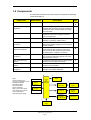
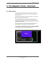
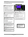
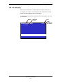
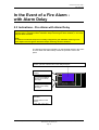
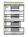
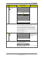
1
Interactive Fire Alarm System
Release 3
Operator's Handbook
Repeater Panel, BU-320
Protecting life, environment and property...
ASAFE-FB/FE Rev. A, 010531
COPYRIGHT ©
This publication, or parts thereof, may not
be reproduced in any form, by any
method, for any purpose.
Autronica Fire and Security AS and its
subsidaries assume no reponsibility for
any errors that may appear in the
publication, or for damages arising from
the information in it. No information in this
publication should be regarded as a
warranty made by Autronica Fire and
Security. The information in this
publication may be updated without notice.
Product names mentioned in this
publication may be trademarks. They are
used only for identification.
Table of Contents
Table of Contents
1. Introduction ..................................................................... 3
1.1
1.2
1.3
1.4
About the Manual...............................................................................3
The Reader ........................................................................................3
Reference Documentation .................................................................3
Components ......................................................................................4
2. The Repeater Panel - Overview...................................... 5
2.1
2.2
2.3
2.4
2.5
Introduction ........................................................................................5
Indication Devices..............................................................................6
The Display ........................................................................................7
Operating Buttons ..............................................................................8
Internal Buzzer ...................................................................................9
3. Operation Mode............................................................... 10
3.1
3.2
3.3
3.4
3.5
3.6
3.7
3.8
3.9
Introduction ........................................................................................10
Conditions in Operation Mode ...........................................................10
Alarm Levels ......................................................................................11
Access Levels ....................................................................................11
How Fire Alarms are Presented in the Display ..................................12
Resounding the Internal Buzzer.........................................................13
Resounding Fire Alarm Devices ........................................................13
Resetting the System.........................................................................13
Alarm Disablement (AlarmDisable) ...................................................14
4. About «In the Event of….».............................................. 15
5. In the Event of a Fire Alarm............................................ 16
5.1
5.2
Indications in the Event of a Fire Alarm .............................................16
Actions to be Taken in the Event of a Fire Alarm ..............................17
6. In the Event of a Fire Alarm - with Alarm Delay ........... 19
6.1
6.2
Indications - Fire Alarm with Alarm Delay..........................................19
Actions to be Taken - Fire Alarm with Alarm Delay ...........................20
Operator's Handbook, AutroSafe Interactive Fire Alarm System, Release 3, ASAFE-FB/FE Rev. A, 010531,
Autronica Fire and Security AS
Page 1
Table of Contents
7. Appendix.......................................................................... 22
7.1
8. Index
Terms and Abbreviations...................................................................22
.......................................................................... 24
9. Figure List ....................................................................... 25
10. Reader’s Comments ....................................................... 27
Operator's Handbook, AutroSafe Interactive Fire Alarm System, Release 3, ASAFE-FB/FE Rev. A, 010531,
Autronica Fire and Security AS
Page 2
Introduction
1. Introduction
1.1 About the Manual
This manual is intended to provide the information necessary to
operate the AutroSafe Interactive Fire Alarm System from the
Repeater Panel, BU-320.
1.2 The Reader
The handbook is intended to be used by the fire brigade and personnel
who are responsible for operating the system. We assume the reader
has the necessary basic understanding of the system concept and the
term zone including, Detection Zone, Alarm Zone and Operation Zone
(refer to System Specification).
The AutroSafe Interactive Fire Alarm System comprises various
components (see chapter 1.0). It is important that the reader gets
familiarized with these, plus the different terms and abbreviations
(shown in Appendix).
1.3 Reference Documentation
In addition to this handbook, the AutroSafe Interactive Fire Alarm
System consists of the following documentation:
Handbook
System Specification
Installation Handbook, Fire Alarm Control Panel (BS-310/320) / Controller (BC-320)
Installation Handbook, Operator Panel (BS-330)
Installation Handbook, Repeater Panel (BU-320) / Information Panel (BV-320)
Installation Handbook, Battery Cabinet (SY-310)
Commissioning Handbook
Operator’s Handbook, Fire Alarm Control Panel (BS-310/320) / Operator Panel (BS-330)
Operator's Handbook, Information Panel (BV-320)
Shortform User Guide
Shortform Configuration Guide (for the AutroSafe Demo Board)
Wall Chart
Wall Chart
Menu Structure
User Guide, Loop Diagnostic Tool, AS-2000
User Guide, Loop Simulator Tool
User Guide, Loop Calculator Tool
User Guide, Merge Tool
User Guide, Power Calculator Sheet
Item Number
P-ASAFE/XE
P-ASAFE-FA/DE
P-ASAFE-OP/DE
P-ASAFE-RI/DE
P-ASAFE-BC/DE
P-ASAFE/EE
P-ASAFE-FO/FE
P-ASAFE-IN/FE
P-ASAFE-SH/LE
P-ASAFE-SH/VE
P-ASAFE-WE/LX
P-ASAFE-CH/LX
P-ASAFE/MX
P-ASAFE-AS/FE
P-ASAFE-LS/FE
P-ASAFE-LC/FE
P-ASAFE-MT/FE
P-ASAFE-PC/FE
Operator's Handbook, AutroSafe Interactive Fire Alarm System, Release 3, ASAFE-FB/FE Rev. A, 010531,
Autronica Fire and Security AS
Page 3
1.4 Components
The AutroSafe Interactive Fire Alarm System comprises the following
components (EN-54) :
Component
Abbreviation
Point
Description
-
Control and indicating
equipment
c.i.e.
Power Supply
-
Ref.
Detector or manual call-point.
A/
D
Equipment supplying power to, as well as
accepting fault and alarm signals from detectors.
Indicates an alarm condition audibly and visibly,
plus the location.
B
The source of power for control and indicating
equipment and for items supplied with power
from such equipment.
L
Equipment used to give warning of fire, for
example, a sounder or visual indicator.
C
Fire Alarm Devices
FAD
Fire Alarm Routing
Equipment
FARE
Equipment used to route an alarm signal from
control and indicating equipment to a Fire Alarm
Receiving Station.
E
Control for Fire
Protection Equipment
FPE
An automatic device used to actuate measures
of fire protection after receiving a signal from
control and indicating equipment (for example,
fire extinguishers, ventilation controllers).
G
Fault Warning Routing
Equipment
FWRE
Equipment used to route a fault warning signal
from control and indicating equipment to a fault
warning receiving station.
J
Fire Alarm Receiving
Station
-
A centre from which the necessary fire protection
measures can be initiated at any time.
F
Fault Warning Receiving
Station
-
A centre from which the necessary corrective
measures can be initiated.
K
Automatic Fire Protection
Equipment
-
Fire control or fire fighting equipment, for
example, extinguishing installation.
H
C
B
Note:
The lines linking the
various components on the
illustration indicate
information flows,
and not physical
interconnections.
Item G and H and some
other items may need to
be provided with a
seperate power supply.
Fire Alarm
Control
and
indicating
equipment
A
Fire
A
detectors
D
C Device
E
F
Fire Alarm
Routing Eq.
Points
Manual
D
call-points
J
Fire Receiving
Station
K
Fault Warning
Receiving
Station
Fault Warning
Routing Eq.
G
Control for
Automatic
Fire Protection Eq.
H
Automatic Fire
Protection Eq.
L
Power
Supply
Operator's Handbook, AutroSafe Interactive Fire Alarm System, Release 3, ASAFE-FB/FE Rev. A, 010531,
Autronica Fire and Security AS
Page 4
The Repeater Panel - Overview
2. The Repeater Panel - Overview
2.1 Introduction
The Repeater Panel is intended to give information related to fire
alarms in the relevant Operation Zone and allow the fire brigade to
operate fire alarms.
The panel is used to silence and resound sounders, and to reset fire
alarms within a defined operation zone.
Each panel is assigned to one operation zone. Relative to its own
zone, a panel is local while it is remote to all other operation zones.
All events and actions occurring in a particular operation zone must be
handled from a local panel.
The whole system can be reset from this panel, provided that the
panel's relation to the operation zone is defined this way.
The panel displays information on fire alarms occurring in all operation
zones. However, the level of details of the given information depends
on which operation zone the information is related to.
ALARM
AUTROSAFE
SelfVerify
Fault
Function Disabled
Mute Panel
Function Delayed
Fire Brig. Signalled
More Events
Silence Alarms
Reset
Power
Operator's Handbook, AutroSafe Interactive Fire Alarm System, Release 3, ASAFE-FB/FE Rev. A, 010531,
Autronica Fire and Security AS
Page 5
The Repeater Panel - Overview
2.2 Indication Devices
Text Display - See chapter 2.3.
ALARM
The red alarm indicator shows that one or more
detection zones within the operating zone of the
Repeater Panel are in the fire alarm state.
ALARM
AUTROSAFE
SelfVerify
• Blinking red light:
In the event of a fire alarm. The Fire Alarm
Devices (FAD) are still in active state.
Fault
Function Disabled
Mute Panel
Function Delayed
• Steady red light:
Fire Brig. Signalled
All FADs activated by the fire alarm condition
have been deactivated by operating the Silence
Alarms button. The control and indicating
equipment still remain in the fire alarm condition.
More Events
Silence Alarms
Reset
Power
More Events
In the event of more than one alarm.
Fault
The yellow Fault Warning indicator shows the
presence of a fault within the operation zone of
the Repeater Panel.
The red More Events indicator shows that several
detection zones within an operating zone are in
the fire alarm state.
• Blinking light
• Blinking red light:
Unaccepted fault warnings exist.
In the event of a fire alarm. The Fire Alarm
Devices (FAD) are still in active state.
• Steady light
• Steady red light:
All fault warnings are accepted.
The Silence Alarms button has been pressed.
All
FADs activated by the fire alarm are no longer
active. The control and indicating equipment
still remain in the fire alarm condition.
Function Disabled
Steady yellow light when one or more of the
following components within the operation zone
of the Repeater Panel are in the disabled state:
•
•
•
•
function delayed
individual points
detection zones
Fire Alarm Devices, Fire Alarm Routing
Equipment, Fire Protection Equipment and
Fault Warning Routing Equipment.
Function Delayed
Steady yellow light indicates that Immediate
Output Actioning has been disabled, i.e. a delay
period is active for Fire Alarm Devices (FAD) or
Fire Alarm Routing Equipment (FARE).
Configurable.
Note that there are several
national variants of this panel.
The Indication Devices shown in
this handbook deals with
the Indication Devices for the
standard panel.
Fire Brig. Signalled
Steady red light when the message is sent to the
Fire Brigade.
Power
Steady green light when power is ON.
Operator's Handbook, AutroSafe Interactive Fire Alarm System, Release 3, ASAFE-FB/FE Rev. A, 010531,
Autronica Fire and Security AS
Page 6
The Repeater Panel - Overview
2.3 The Display
During Normal Operation, the back light in the display is always on.
The display has 16 lines of 40 characters and is divided into several
sections showing different types of information.
The picture below shows the information that is displayed in the event
of a fire alarm.
Header
Detection
Zone(s)
FIRE ALARMS
Time
19:23
Total: 1
Total
number of
fire alarms
1 OFFICES
Operator's Handbook, AutroSafe Interactive Fire Alarm System, Release 3, ASAFE-FB/FE Rev. A, 010531,
Autronica Fire and Security AS
Page 7
The Repeater Panel - Overview
2.4 Operating Buttons
Front Push Buttons
ALARM
AUTROSAFE
Mute Panel
(black)
SelfVerify
Fault
Function Disabled
Mute Panel
Function Delayed
Fire Brig. Signalled
Silence Alarms
(red)
Silence Alarms
More Events
Reset
Power
Reset
(green)
More Events
v
More Events
(black)
Front Push Buttons
Button
Mute Panel
(black)
Silence Alarms
(red)
Designation
Access
Level
Used to mute the panel. Timeout.
1
Used to silence Fire Alarm Devices (FAD) and cause
blinking serial numbers and lamps to go steady.
Timeout.
2
Also used to resound (repress the SILENCE ALARMS
button) after the silence function has been activated
Reset
(green)
Used to reset the system.
2
Can also be used as an accept of alarm (points)
disablement, if points are still in alarm when RESET is
activated.
If the button is pressed more than 5 seconds, a lamp
test is performed (Access Level 1, no key or
password required).
v
More Events
(black)
Used to scroll downwards among alarms in window
(scroll page by page). Possible only if there are more
alarms than possible to display in the window.
Operator's Handbook, AutroSafe Interactive Fire Alarm System, Release 3, ASAFE-FB/FE Rev. A, 010531,
Autronica Fire and Security AS
Page 8
1
The Repeater Panel - Overview
2.5 Internal Buzzer
Each Repeater Panel provides a buzzer which is activated as
described below. Each condition may have its own sound pattern. If
more than one condition is present simultaneously, the state of the
operator panel and the buzzer signal will be decided. The buzzer will
reflect the condition which has the highest priority.
The internal buzzer is controlled by hardware. It is activated in the
cases of:
• System Fault
• Alarm
• Prealarm
• Fault
• Early Warning (not yet implemented)
The buzzer can be silenced by pressing the Mute Panel button. One
exception is the buzzer signal indicating System Fault which can not
be silenced.
If the reason for the buzzer signal still exists, the buzzer will resound
after a predefined time.
Operator's Handbook, AutroSafe Interactive Fire Alarm System, Release 3, ASAFE-FB/FE Rev. A, 010531,
Autronica Fire and Security AS
Page 9
Operation Mode
3. Operation Mode
3.1 Introduction
The Repeater Panel operates in Operation Mode, and will
automatically enter this mode after startup
The display may look as follows in the panel’s idle state.
19:23
Total: 3
AUTROSAFE
SelfVerify
Figure 3-1: The idle display
3.2 Conditions in Operation Mode
In Operation Mode, the system can be in quiescent condition (lowest
priority), or in one or any combination of several conditions. The table
below shows the different conditions, and if / how the conditions are
indicated on the Repeater Panel.
Conditions
Indication
on display
Indicators that are lit
(see also chapter 2.2)
fire alarm condition
(highest priority)
Yes.
ALARM indicator and
Fire Brig. Signalled indicator.
More Events indicator if more
than one fire alarm.
fault warning
condition
No indication.
Fault indicator.
disablement
condition
No indication.
Function Disabled indicator.
Included in
disablement:
No indication
Function Delayed indicator and
Function Disabled indicator
fire warning condition
(including prealarm)
No indication.
No indicators are lit no indication.
test condition
No indication.
No indicators are lit no indication.
Immediate actioning
disabled condition
Note that only fire alarms are indicated on the Repeater Panel's
display.
Operator's Handbook, AutroSafe Interactive Fire Alarm System, Release 3, ASAFE-FB/FE Rev. A, 010531,
Autronica Fire and Security AS
Page 10
Operation Mode
3.3 Alarm Levels
A detector may signal different levels of alarm, indicating the amount
of smoke or gas currently present. These are;
• Fire Alarm Level (the highest level)
• Fire Warning, including:
- Prealarm Level
- (the lowest level Early Warning is not yet implemented)
Note that only the Fire Alarm Level is indicated on the Repeater Panel
BU-320.
Whenever a detector detects a transition from one alarm level to
another, this event is reported to the system as an Early Warning (not
yet implemented), Prealarm or Fire Alarm signal, which in turn will
initiate the appropriate actions.
3.4 Access Levels
All user interface controls are classified as belonging to different
access levels. To operate the Repeater Panel, Access Level 2 is
required. (To mute the internal buzzer, Access Level 1 or higher is
required).
Access
Level
Access Remedy
Description
1
No key or password
required.
Accessible by members of the general public. All mandatory
indications are visible at access level 1 without prior manual
intervention.
2
Access by key.
Accessible by persons having a specified responsibility for
safety.
4
Mechanical tool.
Accessible by persons doing repair work and changing
firmware.
Operator's Handbook, AutroSafe Interactive Fire Alarm System, Release 3, ASAFE-FB/FE Rev. A, 010531,
Autronica Fire and Security AS
Page 11
Operation Mode
3.5 How Fire Alarms are Presented in the Display
Fire alarms are presented in Operation Mode. FIRE ALARMS is shown
in the upper left corner of the display.
The example below shows a situation where three zones are in alarm
state. The total number of zones in alarm is shown in the upper right
corner.
Header
Detection
Zone(s) in
fire alarm
FIRE ALARMS
Time
19:23
Total: 3
Total
number of
fire alarms
1 OFFICES
2 CANTEEN
3 WORKSHOP
Figure 3-2: How fire alarms are presented
Operator's Handbook, AutroSafe Interactive Fire Alarm System, Release 3, ASAFE-FB/FE Rev. A, 010531,
Autronica Fire and Security AS
Page 12
Operation Mode
3.6 Resounding the Internal Buzzer
After pressing the MUTE PANEL button in an alarm condition, the
internal buzzer will automatically be resounded in the following cases:
• if any new fire alarms occur (for example, if a detection zone enters
the Fire Alarm state)
• after a timeout period if the cause for making it sound is still
present.
3.7 Resounding Fire Alarm Devices
When pressing the SILENCE ALARMS button in the event of an
alarm, all fire alarm devices (FAD) within the operation zone of the
operator panel will be deactivated. The red Fire Alarm indication lamp
will switch from blinking to steady light.
At this stage, the resound timer will start.
Depending on the current alarm situation, the alarm zones are
automatically resounded to their alarm states on timeout (configurable)
of the SILENCE resound timer, or they can be manually resounded to
their alarm states when repressing the SILENCE ALARMS button.
3.8 Resetting the System
In order to reset the system by pressing the RESET button, all Fire
Alarm Devices (FAD) have to be silenced / deactivated using the
SILENCE ALARMS button. Otherwise the reset operation will be
rejected without having any effect on system behaviour.
Operator's Handbook, AutroSafe Interactive Fire Alarm System, Release 3, ASAFE-FB/FE Rev. A, 010531,
Autronica Fire and Security AS
Page 13
Operation Mode
3.9 Alarm Disablement (AlarmDisable)
If there are points within an operation zone still signalling a Fire Alarm
after the reset button has been pressed, an alarm disablement will
take effect.
Alarmdisabling may or may not be required to be confirmed by the
operator (configurable).
• If confirmation is not required, all points still signalling a Fire Alarm,
are automatically disabled.
• If confirmation is required, a list of points in alarm is presented on
the display. To confirm automatic disablement, the Reset button
must be pressed within 5 seconds (configurable).
The alarmdisabled detectors cannot be reactivated with the Repeater
Panel. This can be done by means of the Fire Alarm Control Panel BS320 or Operator Panel BS-330.
Operator's Handbook, AutroSafe Interactive Fire Alarm System, Release 3, ASAFE-FB/FE Rev. A, 010531,
Autronica Fire and Security AS
Page 14
About «In the Event of….»
4. About «In the Event of….»
The subsequent chapters - In the event of deal with different events
that may occur;
Chapter
In the event of…..
Chapter 5
a fire alarm
Chapter 6
a fire alarm with alarm delay (in a Delayed Action detection
zone - immediate output actioning disabled)
The operational information included in chapter 3, plus the overview of
buttons and indicators in chapter 2, are intended to provide the
information necessary to successfully operate the AutroSafe
Interactive Fire Alarm System by means of the Repeater Panel.
For each event there is an overview of all indications on the panel,
plus the necessary actions to take. All alarm handling and display
pictures shown in the subsequent chapters are based on the following:
• To operate the panel, Access Level 2 is required. This means that
the person who operates the panel, must use a key before the
panel can be operated. This is indicated with a key.
• The examples show a system that is configured to immediately
trigger Fire Alarm Routing Equipment and send a message to a
Fire Receiving Station (Fire Brigade) in the event of a fire alarm.
The Fire Brig. Signalled indicator will thus come on.
• In many cases, several display pictures will be shown when a
command has been executed. These quick changes from one
display picture to another are indicated with an arrow.
• The table for the different procedures is divided into four columns
with the following headings;
Step
Actions to be taken
Display Indication
Audible Indication
Operator's Handbook, AutroSafe Interactive Fire Alarm System, Release 3, ASAFE-FB/FE Rev. A, 010531,
Autronica Fire and Security AS
Page 15
In the Event of a Fire Alarm
5. In the Event of a Fire Alarm
5.1 Indications in the Event of a Fire Alarm
One or several fire detectors or manual call points in one or several detection zones are
signalling a Fire Alarm.
The following shows the indications on the Repeater Panel in the event
of «Fire Alarm» within the operation zone of the panel.
The text display indicates the detection zones in alarm state and their
location.
The red Alarm indicator is
blinking.
ALARM
Fault
Function Disabled
The Fire Brig. Signalled
indicator has a steady red
light.
Mute Panel
Function Delayed
Fire Brig. Signalled
Power
More Events
Silence Alarms
Reset
The internal buzzer is
activated.
Default pattern on the
sound:
1 sec. ON, 1 sec. OFF
Activated functions:
A message is sent to the Fire Brigade.
The fire alarm condition activates Fire Alarm Devices (sounders and visual
indicators).
Operator's Handbook, AutroSafe Interactive Fire Alarm System, Release 3, ASAFE-FB/FE Rev. A, 010531,
Autronica Fire and Security AS
Page 16
In the Event of a Fire Alarm
5.2 Actions to be Taken in the Event of a Fire Alarm
Step
Actions to be taken
1
Follow all precautions
described in the local
fire instructions, step by
step.
Display Indication
FIRE ALARMS
Audible Indication
19:23
Total: 3
1 OFFICES
2 CANTEEN
3 WORKSHOP
All fire alarm devices
connected to the
alarm zones (which
are connected to the
detection zones in
alarm) are activated
(sounders and visual
indicators).
The internal buzzer on
the Repeater Panel is
turned on.
Comments:
2
3
The red FIRE indicator starts to blink.
The red Fire Brig. Signalled indicator is lit.
When several zones are in alarm state, the More Events indicator is lit.
To silence the internal
buzzer, press the black
Mute Panel button
FIRE ALARMS
Observe the zone(s) in
alarm state in the
display.
FIRE ALARMS
19:23
Total: 3
1 OFFICES
2 CANTEEN
3 WORKSHOP
The internal buzzer on
the Repeater Panel is
turned off.
19:23
Total: 3
1 OFFICES
2 CANTEEN
3 WORKSHOP
Investigate the scene(s)
and carry out the
necessary actions.
Comments:
4
To silence all alarms,
press the red Silence
Alarms button.
In this example, a total of 3 zones are in alarm state.
SILENCE
Info
:
19:23
All Fire Alarm Devices
(FAD) are deactivated.
Completed
FIRE ALARMS
3 WORKSHOP
Total: 3
FIRE ALARMS
19:23
Total: 3
1 OFFICES
2 CANTEEN
3 WORKSHOP
Comments:
The red FIRE indicator goes steady.
The alarm zones are automatically resounded to their alarm states on
timeout of the silence resound timer.
When the fire is extinguished and all necessary repair work have been
carried out (smoke is exhausted, new glass replaced in the manual callpoints, etc.), the system should be returned to normal operating mode.
The SILENCE ALARMS button has to be pressed before pressing the
RESET button. Otherwise the reset operation will be rejected without
having any effect on system behaviour.
Operator's Handbook, AutroSafe Interactive Fire Alarm System, Release 3, ASAFE-FB/FE Rev. A, 010531,
Autronica Fire and Security AS
Page 17
In the Event of a Fire Alarm
Step
Actions to be taken
Display Indication
Audible Indication
By means of the SILENCE button, you can manually resound the alarm
zones at this stage.
5
Press the green Reset
button.
Info
Comments:
19:23
Total: 19:23
3
RESET
The audible indicator
on all panels within
the operation zone of
the Repeater Panel is
turned off.
: Completed
If there are no points signalling a fire alarm, the system is reset.
The red FIRE indicator goes off.
The red Fire Brig. Signalled indicator goes off.
The panel enters its idle state.
AUTROSAFE
SelfVerify
If there are points still
signalling an alarm when the
system is reset, continue as
follows:
The point(s) still in alarm will be
shown on the display.
RESET
19:23
Total: 19:23
3
If no actions are taken, the
points still signalling alarm will
automatically be reactivated
after a predefined timeout.
POINTS IN ALARM
19:23
Total:19:23
3
If you want to disable the
point(s) - for example, a manual
call-point -still signalling alarm,
go to step 6.
6
To disable all points still
signalling alarm, press
the green Reset button.
P6
Press ‘RESET’ to disable all points.
ALARM DISABLE
19:23
Total: 19:23
3
RESET
19:23
Total: 19:23
3
AUTROSAFE
SelfVerify
Comments:
The red Fire Brig. Signalled indicator goes off.
The yellow Function Disabled indicator is lit.
The display on the Fire Alarm Control Panel BS-320, Operator Panel BS-330
or Information Panel BV-320 will indicate the points that have been disabled.
By means of the Fire Alarm Control Panel BS-320 or Operator Panel BS330, you can; reactive the points (press Action Digit 1: Reactivate) or enable
the points that have been disabled (select the point and press Action Digit 3:
Enable).
Operator's Handbook, AutroSafe Interactive Fire Alarm System, Release 3, ASAFE-FB/FE Rev. A, 010531,
Autronica Fire and Security AS
Page 18
In the Event of a Fire Alarm with Alarm Delay
In the Event of a Fire Alarm with Alarm Delay
5.3 Indications - Fire Alarm with Alarm Delay
A point set to Delayed Action (configurable) is sending an alarm signal from a Delayed Action
detection zone in a situation where Immediate Output Actioning has been disabled, i.e. the alarm
delay has been activated.
NOTE:
An alarm from a manual call-point is normally configured to give immediate actioning on the
alarm outputs even though the Immediate Output Actioning has been disabled.
The following shows the indications on the Repeater Panel in the event
of «Fire Alarm with Alarm Delay» within the operation zone of the
panel.
The text display indicates the detection zones in alarm state and their
location, plus the activation time of the delayed outputs.
The red Alarm indicator is
blinking.
ALARM
The Function Disabled
indicator has a steady
yellow light.
Fault
Function Disabled
Mute Panel
Function Delayed
Fire Brig. Signalled
The Function Delayed
indicator has a steady
yellow light.
Power
More Events
Silence Alarms
Reset
The internal buzzer is
activated.
Default pattern on the
sound:
1 sec. ON, 1 sec. OFF
Operator's Handbook, AutroSafe Interactive Fire Alarm System, Release 3, ASAFE-FB/FE Rev. A, 010531,
Autronica Fire and Security AS
Page 19
In the Event of a Fire Alarm with Alarm Delay
5.4 Actions to be Taken - Fire Alarm with Alarm Delay
Step
Actions to be taken
1
Follow all precautions
described in the local
fire instructions, step by
step.
Comments:
Display Indication
Audible Indication
19:23
Total: 1
FIRE ALARMS
1* KITCHEN
FIRST DELAYED OUTPUTS ACTIVATES 19:30
The internal buzzer on
the Repeater Panel is
turned on.
The red FIRE indicator starts to blink.
The FUNCTION DELAYED and FUNCTION DISABLED indicators have a
steady yellow light indicating that Immediate Output Actioning has been
disabled (manual operation in Menu Mode by means of the Fire Alarm
Control Panel BS-320 or the Operator Panel BS-330).
In this example, one point in a Delayed Action detection zone is signalling an
alarm.
2
3
To silence the internal
buzzer, press the black
Mute Panel button
FIRE ALARMS
Observe the zone(s) in
alarm state in the
display.
FIRE ALARMS
19:23
Total: 1
1* KITCHEN
FIRST DELAYED OUTPUTS ACTIVATES 14:40
The internal buzzer on
the Repeater Panel is
turned off.
19:23
Total: 1
1* KITCHEN
FIRST DELAYED OUTPUTS ACTIVATES 14:40
Investigate the scene(s)
and carry out the
necessary actions.
4
The next step in the procedure will depend on whether or not there really is a fire.
Follow
4a
4a
if there is not a fire - or follow
4b
If there is not a fire,
press the green Reset
button.
if there really is a fire.
19:23
Total: 19:23
3
RESET
AUTROSAFE
SelfVerify
Comments:
4b
If there really is a fire,
activate the nearest
manual call-point or go
to the nearest operator
panel (BS-320/330) to
activate the alarm.
The red FIRE indicator goes off.
The idle display is shown.
FIRE ALARMS
1 KITCHEN
19:23
Total: 1
All fire alarm devices
within the operation
zone of the panel
(sounders and visual
indicators) are
activated.
Implement the
necessary measures.
Comments:
The red Fire Brigade Signalled indicator is lit.
If the delay time expires, all fire alarm devices within the alarm zones
assigned to the actual detection zones (sounders and visual indicators)
will automatically be activated.
Operator's Handbook, AutroSafe Interactive Fire Alarm System, Release 3, ASAFE-FB/FE Rev. A, 010531,
Autronica Fire and Security AS
Page 20
In the Event of a Fire Alarm with Alarm Delay
Step
Actions to be taken
5b
To silence all alarms,
press the red Silence
Alarms button.
Display Indication
19:23
Total: 19:23
3
SILENCE
Info:
Audible Indication
All Fire Alarm Devices
(FAD) are deactivated.
Completed
FIRE ALARMS
1 KITCHEN
Total: 1
FIRE ALARMS
19:23
Total: 1
1 KITCHEN
Comments:
The red FIRE indicator goes steady.
The alarm zones previously in alarm state are automatically resounded to
their alarm state on timeout of the silence resound timer.
When the fire is extinguished and all necessary repair work have been
carried out (smoke is exhausted, new glass replaced in the manual callpoints, etc.), the system should be returned to normal operating mode.
The SILENCE ALARMS button has to be pressed before pressing the
RESET button. Otherwise the reset operation will be rejected without having
any effect on system behaviour.
By means of the SILENCE ALARMS button, you can manually resound the
alarm zones at this stage.
6b
Press the green Reset
button.
Info
Comments:
19:23
Total: 19:23
3
RESET
The audible indicator
on all panels within
the operation zone of
the Repeater Panel is
turned off.
: Completed
If there are no points signalling a fire alarm, the system is reset.
The red FIRE indicator goes off.
The red Fire Brig. Signalled indicator goes off.
AUTROSAFE
SelfVerify
If there are points still signalling a fire alarm, refer to step 6 in the procedure
described in the previous chapter.
Operator's Handbook, AutroSafe Interactive Fire Alarm System, Release 3, ASAFE-FB/FE Rev. A, 010531,
Autronica Fire and Security AS
Page 21
Appendix
6. Appendix
6.1 Terms and Abbreviations
Term / Abbreviation
Explanation
Activation
To bring a component into (one of) its active activation states (depending
on type, a component may have several active activation states). Examples
of activation are turning a fire extinguisher on and making a sounder to
issue a EVACUATE or ALERT signal. Components may be activated and
deactivated either on command or on alarm.
Alarm Zone
The geographical area throughout which Fire Alarm Devices give identical
alarm signals present identical audible information in response to the same
event. An alarm zone is activated by one or several Detection Zones.
The alarm zone assigned to the detection zone in alarm is called the parent
alarm zone. Fire Alarm Devices in a parent alarm zone will always give
EVACUATE signal.
To any (parent) alarm zone there may be defined a number of neighbour
alarm zones. Fire Alarm Devices in neighbour alarm zones will give alert
signal when its parent alarm zone gives EVACUATE signal.
AUTROLON
Autronica’s Local Operating Network
BLC-Eq
Basic Loop Controller Equipment (equipment part for all Loop Units and I/O
modules, i.e. Eq-part for Loop-Ctrl, Point-Ctrl, FPE-Ctrl etc.)
Component
An assembly of one or more modules, implementing a system function.
The following components are defined in the AutroSafe Interactive Fire
Alarm System (also see detailed description of Components, Chapter 1):
• Points (fire detectors, manual call points)
• Detection Zones
• Fire Protection Equipment (fire extinguishers, ventilation controllers)
• Fire Alarm Devices (sounders, information panel, visual indicator)
• Fire Alarm Routing Equipment
• Fault Warning Routing Equipment
• Operator Panels
Condition
Meaning similar to «state», but used only in conjunction with the control
and indication equipment. (EN54 standard).
Control and indicating
equipment (c.i.e)
Equipment supplying power to, as well as accepting fault and alarm signals
from detectors. A c.i.e. will indicate an alarm condition audibly as well as
visibly and indicate the location of danger.
Deactivation
To bring a component into its inactive activation state (a component can
have only one inactive activation state). Examples of deactivation are
turning a fire extinguisher off and silencing a sounder.
Detection Loop
Loop circuit connecting a number of fire detectors, manual call-points and
other Loop Units. A detector loop is connected to control and indicating
equipment.
Detection Zone
One or more fire detectors and/or manual call-points logically belonging
together for geographical, functional or other reasons.
Domain Network
The domain network consists of a number of components, connected over
AUTROLON.
Fault Warning Routing
Equipment (FWRE)
Intermediate equipment which routes a fault warning signal from (B) to a
fault warning signal receiving station.
Fire Alarm Device
(FAD)
Equipment used to give warning of fire, for example, sounder or visual
indicator.
Fire Alarm Recieving
Station
A centre from which the necessary fire protection measures can be
initiated at any time.
Operator's Handbook, AutroSafe Interactive Fire Alarm System, Release 3, ASAFE-FB/FE Rev. A, 010531,
Autronica Fire and Security AS
Page 22
Appendix
Term / Abbreviation
Explanation
Fire Alarm Routing
Equipment (FARE)
Intermediate equipment which routes an alarm signal from control and
indicating equipment to a Fire Alarm Receiving Station.
Fire Detector
The part of an automatic fire detection system which constantly or at
frequent intervals monitors suitable physical and/or chemical phenomena
for detection of fires in the area under surveillance.
Fire Protection
Equipment (FPE)
Fire control or fighting equipment, e.g. extinguishing installation.
Loop Unit
Either a Point, and I/O-unit or and Electronic Sounder that is connected to
a Detection Loop.
Manual Call-Point
A device for the manual initiation of an alarm.
Operation Zone
An Operation Zone defines the scope of an Operator Panel. One operation
zone may encompass one or more detection zones. Operation zones are
allowed to be contained in other operation zones, building an hierarchy
consisting of different levels of operation zones.
Operation zones must be fully contained in each other, i.e. the operation
zone can not be partly contained in (overlap) another operation zone.
One operation zone may be controlled by more than one Operator Panel.
Point
Detectors or manual call-points. Each point is assigned zone membership
on individual basis. A point can be a member of one detection zone only.
A point may signal a number of different alarm levels. A manual call-point
can only signal a Fire Alarm Level.
To each point there will be assigned a delay parameter, notifying whether
actions to be initiated upon reception of a Fire Alarm signal from the point
should be delayed or not. The delay parameter is only valid in conjunction
with Delayed Action or SOLAS.
SOLAS
A program version of the AutroSafe software, spesially designed for
maritime application - Safety Of Life At Sea (SOLAS).
SVD
Self Verifying Detection
Operator's Handbook, AutroSafe Interactive Fire Alarm System, Release 3, ASAFE-FB/FE Rev. A, 010531,
Autronica Fire and Security AS
Page 23
Index
7. Index
access levels, 11
automatic disablement, 14
buzzer, 9
components, 4
conditions, 10
Fire Alarm, 16
Fire Alarm with Alarm Delay,
20
Front Push Buttons, 8
In the event of…..-, 15
levels of alarm, 11
Mute Panel, 8
Operation Mode, 10
RESET button, 13
Reset System, 8
Silence Alarms, 8
Operator's Handbook, AutroSafe Interactive Fire Alarm System, Release 3, ASAFE-FB/FE Rev. A, 010531,
Autronica Fire and Security AS
Page 24
Figure List
8. Figure List
Figure 3-1: The idle display........................................................................10
Figure 3-2: How fire alarms are presented ..............................................12
Operator's Handbook, AutroSafe Interactive Fire Alarm System, Release 3, ASAFE-FB/FE Rev. A, 010531,
Autronica Fire and Security AS
Page 25
Operator's Handbook, AutroSafe Interactive Fire Alarm System, Release 3, ASAFE-FB/FE Rev. A, 010531,
Autronica Fire and Security AS
Page 26
Reader’s Comments
9. Reader’s Comments
Please help us to improve the quality of our documentation by returning your comments on this
manual:
Title: Operator's Handbook, Repeater Panel, BU-320
AutroSafe Interactive Fire Alarm System, Release 3,
Ref. No.: ASAFE-FB/FE Rev. A, 010531
Your information on any inaccuracies or omissions (with page reference):
Please turn the page
Operator's Handbook, AutroSafe Interactive Fire Alarm System, Release 3, ASAFE-FB/FE Rev. A, 010531,
Autronica Fire and Security AS
Reader’s Comments
Suggestions for improvements
Thank you! We will investigate your comments promptly.
Would you like a written reply?
❑ Yes
❑ No
Name:
------------------------------------------------------------------------------------------------
Title:
------------------------------------------------------------------------------------------------
Company:
------------------------------------------------------------------------------------------------
Address:
----------------------------------------------------------------------------------------------------------------------------------------------------------------------------------------------------------------------------------------------------------------------------------------------
Telephone:
------------------------------------------------------------------------------------------------
Fax:
------------------------------------------------------------------------------------------------
Date:
------------------------------------------------------------------------------------------------
Please send this form to:
Autronica Fire and Security AS
N-7483 Trondheim
Norway
Tel: + 47 73 58 25 00
Fax: + 47 73 58 25 01
www.autronicafire.com/
Operator's Handbook, AutroSafe Interactive Fire Alarm System, Release 3, ASAFE-FB/FE Rev. A, 010531,
Autronica Fire and Security AS
Autronica Fire and Security AS is an international company, based in Trondheim, Norway and has
a world-wide sales and service network. For more than 40 years Autronica’s monitoring systems have
been saving lives and preventing catastrophes on land and at sea. Autronica Fire and Security’s most
important business area is fire detection & security. Autronica Fire and Security stands for
preservation of environment, life and property.
Quality Assurance
Stringent control throughout Autronica Fire and Security assures the excellence of our products and
services. Our quality system conforms to the Quality System Standard NS-EN ISO 9001, and is
valid for the following product and service ranges: marketing, sales, design, development,
manufacturing, installation and servicing of:
•
•
fire alarm and security systems
petrochemical, oil and gas instrumentation systems for monitoring and control
In the interest of product improvement, Autronica Fire and Security reserves the right to alter
specifications according to current rules and regulations.
Autronica Fire and Security AS
Fire and Security, Trondheim, Norway. Phone: + 47 73 58 25 00, fax: + 47 73 58 25 01.
Oil & Gas, Stavanger, Norway. Phone: + 47 51 84 09 00, fax: + 47 51 84 09 99.
Autronica Industrial Ltd., Watford, United Kingdom. Phone: 1923 23 37 68, fax: 1923 22 55 77.
Visit Autronica Fire and Security's Web site: http://www.autronicafire.com/