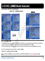
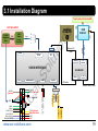
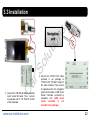
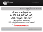
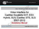
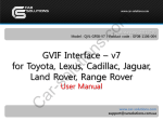
1
ns tio Release date : 2011.07.19 Model : QVI-AUD09-V6 / Product code : AUD09-1107-001 So lu Video Interface for AUDI 2009-2011~ model years C ar With MMI 3G/3G+ head units With external touch screen panel support Installation Manual www.car-solutions.com [email protected] Contents 1. Before installation tio ns 1.1 Main specifications 1.2 Features 1.3 System diagram 1.4 Components 1.5 Exterior 3. Installation C ar So 2.1 DIP switches 2.2 Remote controller 2.3 Original buttons in car 2.4 OSD buttons activation 2.5 OSD Menu (On Screen Display) 2.6 FACTORY mode 2.7 Rear view camera parking guideline 2.8 Touch screen panel calibration 2.9 Remote controller buttons 2.10 DVD, DVB-T model selection lu 2. Setup 3.1 Installation diagram 3.2 Cautions on installation 3.3 Installation 3.4 Using original navigation button 3.5 CAN cable connection 4. Troubleshooting www.car-solutions.com 3 4 5 6 7 8 9 10 11 12 13 14 15 16 18 19 20 21 23 24 25 2 1.1 Main Specifications tio ns 1. Inputs (MULTI VIDEO INTERFACE) - 1 x Analog RGBCs (for navigation system) - 1 x REAR-C Input (for external rear camera source, supports NTSC & PAL auto detection) - 3 x A/V Input (for external video source - DVD, TV, DVB-T; supports NTSC & PAL auto detection) - 1 x SYS Input – To SYS (video input from MMI 3G unit) - 1 x Touch In – To Touch (for external touch screen panel) So lu 2. Outputs - 2 X A/VOUT (video/audio output for headrest monitors) - 1 x Touch OUT To Navi (for external touch screen panel connection to navigation box connected via RGBCs input) - 1 X Monitor Output – To Monitor (video output for connection to OEM display) - 1 X R-CAM (power output for external rear camera connected via REAR-C input) C ar 3. Power - Input Power: 10 V DC ~ 16 V DC - Consumption Power : 6 W (max) 4. Mode change - Video input disable: possible to skip each input source by adjusting DIP switches - Control by using the remote controller - Possible to switch between modes by remote mode switch button - Possible to change modes and control DVD, CMMB via external touch screen panel - Possible to change modes via using original buttons (navigation) NAVI, MODE… www.car-solutions.com 3 1.2 Features ns DVD, DVB-T and Navigation unit control via external touch screen panel tio DVD, DVB-T, navigation control via OEM MMI 3G buttons Installation near MMI 3G unit lu Plug & Play installation (LVDS cable offered) So Possibility to adjust position of AV1-3, RGB image Screen display adjustment (user friendly interface) C ar Remote control unit Mode change via OEM MODE switch on the wheel (only when connected to CAN bus) Control of rear view camera power www.car-solutions.com 4 1.3 System Diagram ns TOUCH CONTROLLER lu NAVIGATION LCD INPUT\OUTPUT SUB BOARD VIDEO CIRCUIT C ar REAR-C (external rear camera input) OEM LCD Video Interface A/V1 Input A/V3 Input LVDS So RGB input for Navigation unit A/V2 Input MCU MMI 3G UNIT tio DVD IR DVB-T IR MODE Button DIP Switches Remote control POWER CIRCUIT External Touch Panel VIDEO MUX Headrest Monitors Power Input (+10 V DC~+16 V DC) www.car-solutions.com 5 LVDS cable * 1pc. lu So Cable with remote mode switch button * 1pc. TOUCH IN cable * 1pc. C ar RGB cable * 1pc. OEM cable * 1pc. tio TOUCH OUT cable * 1pc. IR cable * 1pc. ns 1.4 Components POWER cable (24P) * 1pc. www.car-solutions.com Rear camera power cable * 1pc. AV cable * 1pc. Remote control * 1pc. 6 1.5 Exterior SUB BOARD ⑥ (47*38*22) ⑤ Dimension ⑩ Horizontal length 146 mm Vertical length 88 mm Height 25 mm ⑤ tio ⑥ ⑪ lu ⑦ ns ⑦ ① LED So ② POWER/CAN/RGB ③ REAR CAMERA POWER ① ② C ar ④ AV (IN/OUT) ③ ④ ⑤ LVDS OUT ⑥ TOUCH OUT TO NAVI ⑦ DIP S/W ⑧ ⑨ ⑧ TO VIDEO INTERFACE ⑨ TO TOUCH SCREEN PANEL ⑩ TO OEM DISPLAY ① ② ③ www.car-solutions.com ④ ⑪ TO MMI 3G UNIT 7 2.1 DIP Switches RGB Input ON : RGB Input is OFF OFF : RGB Input is ON 2 A/V1 Input ON : A/V1 Input is OFF OFF : A/V1 Input is ON 3 A/V2 Input ON : A/V2 Input is OFF OFF : A/V2 Input is ON A/V3 Input 5 OEM Display Size 7 8 - Inputs to be used: A/V3(DVD), CS9100 navigation box (RGB) - External rear view camera: connected to REARC input ON : 7” LCD with 800*480 Resolution OFF : 6.5” LCD with 400*240 Resolution NOT USED C ar 6 ON : A/V3 Input is OFF OFF : A/V3 Input is ON [AUDI 2009 LCD 6.5”] So 4 ns 1 Rear Mode DIP ※ ON : DOWN, OFF : UP DIP S/W selection tio Function lu DIP # ▷ ▷ ▷ ▷ ▷ ▷ ▷ ▷ DIP S/W : 1 OFF (RGB input is ON) DIP S/W : 2 ON (A/V1 inputs is OFF) DIP S/W : 3 ON (A/V2 inputs is OFF) DIP S/W : 4 OFF (A/V3 is ON) DIP S/W : 5 OFF (6.5” LCD) DIP S/W : 6 OFF (NOT USED) DIP S/W : 7 ON (REAR-C input is ON) DIP S/W : 8 OFF (NOT USED) ON : External Rear Camera OFF : OEM Rear Camera NOT USED www.car-solutions.com 8 Function POWER & PIP NOT USED lu OK OSD Menu Selection or Mode change Move UP So MENU tio Buttons ns 2.2 Remote Controller C ar Move DOWN Move LEFT (or press 2 sec. – Factory Mode) Move RIGHT (or press 2 sec. - Factory Reset) www.car-solutions.com 9 2.3 Original Buttons on MMI Panel or On Wheel ① ③ ⑩ ⑨ ns ⑧ ④ ⑥ NAVIGATION control Temporarily NOT USED DVD, DVB-T control MODE CHANGE ⑤ Confirm ⑨ Move counterclockwise ⑩ Move clockwise If there is the MODE handle button on the steering wheel and interface is connected to CAN bus, driver can change modes by the MODE button. C ar ① Move UP ② Move Down ③ Magnification ④ Reduction ⑤ Confirm; press 2 sec. - Menu ⑥ Return - press 2 sec. ⑦ Setup for destination. If pressed 2 sec. - Night Mode ⑧ Mode change ⑨ Move Left ⑩ Move Right So ⑦ lu ② www.car-solutions.com tio ⑤ ※ If you press any of these three buttons, DVD/DVB-T OSD menu will appear on the screen. Hold MODE button: Return to main image Press MODE button: Mode change 10 2.4 OSD Buttons Activation OSD Buttons for DVD ns For DVD control via OSD menu installer shall connect DVD system to AV1 input and join “DVD IR” cable from video interface cables with DVD IR receiver DATA cable. tio First of all, if you touch the screen in mode ”AV1”, you can see the menu as shown left. And then if you do NOT touch anything on the screen for 5 seconds or longer; or if you touch the screen in the place beyond menu, the menu will disappear. At that time, if you choose “INPUT”, you can get out of the menu and see the mode change menu.(left picture) So lu > Here is a picture of the mode change menu. If you select the channel which you want, you will switch to selected video source. (right picture) OSD Buttons for DVB-T (CMMB), NAVI C ar DVD, navigation menu is available in English or Chinese. You can change menu language by pushing “MENU” button on remote controller. >>> www.car-solutions.com As shown above, if you touch the screen in mode ”AV2”, you can see the menu as shown left. And then if you do NOT touch anything on the screen for 5 seconds or longer; or if you touch the screen in the place beyond menu, the menu will disappear.(left picture) Here is a picture of the mode change menu. If you select the channel which you want, you will switch to selected video source. (right picture) 11 2.5 OSD Menu (On Screen Display) OSD menu: Press ”MENU” button on the remote controller. Analog RGB mode Video AV1-3 mode Video AV1-3 mode Analog RGB mode Video AV1-3 mode IMAGE C ar So lu tio ns Analog RGB mode - BRIGHTNESS - CONTRAST - SATURATION - HUE - SHARPNESS - USER IMAGE: To choose among 4 prepared color shades. www.car-solutions.com OSD UTIL - LANGUAGE : To change DVD, CMMB OSD menu language (select 1 among English or Chinese) - TRANS: OSD background transparency adjustment control of the - H_POSITION : Horizontal movement of the OSD window - V_POSITION : Vertical movement of the OSD window - FACTORY RESET: To restore navigation, DVD screen factory settings. (DOES NOT restore images position, only functions inside OSD menu) 12 2.6 Factory Mode Factory mode: press ◀ button for 2 sec. IMAGE PARK lu tio ns - H-POSITION: horizontal movement of screen (image alignment) - V-POSITION : vertical movement of the screen (image alignment) - NAVI MODEL (RGB input resolution) : DEFAULT – 480x234(400x234), KD900(WVGA) 800x480, MD7000(WVGA) 800x480, MYVI(WVGA) 800x480, PAPAGO(WVGA) 800x480 - CAR MODEL : DEFAULT, 2011 A7,8-NEW - AVOUT SELECT : DEFAULT, AV1, AV2, AV3 (select output for installed headrest monitor) C ar So - PARK ENABLE: Rear view camera parking guidelines activation. - PARK SETUP : rear view camera parking guideline position adjustment (refer to page 14.) - REAR SELECT (type of rear view camera image activation): CAN – by Can bus, LAMP – by real lamp - SAFE ENABLE: SAFE function activation (DOES NOT allow you to watch video while driving) UTIL - CALIBRATION: External touch screen panel calibration (Refer to page15) - IR MEMORY: To program value of remote controller buttons (Refer to page16~17.) - DVD TYPE: DVD type setup (Refer to page18.) - CMMB TYPE: Setup for the type of DMB (Refer to page18.) - MMI CONTROL: DVD and CMMB control by MMI buttons - FACTORY RESET: To restore all factory settings www.car-solutions.com 13 2.7 Rear View Parking Guideline Factory mode: press ◀ button 2 sec. tio ns ① Set “ON” in “PARK ENABLE” line in the PARK section as shown left. (default – ON) . In case camera you want to connect already has parking lines, you should turn this function off in order to avoid parking lines and rear view camera image overlapping. To do this set “OFF”. C ar So lu ② If you turn rear gear after setup, parking guidelines will appear on screen as shown left. Now if you push “OK” button, you can see “H-POS” on the left of screen. Then adjust horizontal position of the parking guidelines. ③ After horizontal position adjustment, press “OK” on the remote controller. Then you will see “V-POS” on the left of screen. Adjust vertical position of the guideline. www.car-solutions.com 14 2.8 Touch calibration tio ns If you use external touch screen panel for connected DVD player, TV tuner, DVB-T receiver control by OSD buttons, which will emulate remote controller buttons of these devices, you should calibrate the connected touch screen panel. C ar So lu >>> ① First of all, press ◀ button on remote controller for 2 seconds. Then you can enter the FACTORY mode. ② Set “YES” after CALIBRATION option is selected as shown above. www.car-solutions.com ③ After that “touch calibration” caption will appear on screen for about 2 seconds as shown above. When it disappears you can calibrate the touch screen. (Just touch on screen.) If calibration was performed, “success” caption will appear. If not, you will see “failure”. 15 2.9.1 Remote Controller Button tio ns Programming OSD buttons value using remote controller supplied together with DVD,TV,DVB-T. If you want to control DVD and DMB models other than SANYO and NECVOX via touch screen (using OSD menu, you can program value of DVD and DMB’ s remote controller which you have. Then you can control DVD and DMB via touch screen. So lu >>> C ar ① First of all, press ◀ button on remote controller for 2 seconds. Enter FACTORY mode, then select IR MEMORY in UTIL section. There are two options in IR MEMORY as shown above; DMB and DVD. Select one of these AV sources. www.car-solutions.com ② This is a window where DVD remote controller button values are programmed. Just select a menu you want to save. (Select “DMB in options of IR MEMORY” if you want to save values of DMB’ s remote controller. And follow the instruction below.) Programming Instructions> a. Select “POWER” in OSD menu, then press “OK” on remote controller. (as shown above) b. If the marked area flickers as shown above, press “POWER” button on the remote controller of DVD that you want to use. (continued on the next page) 16 So lu tio >>> ns 2.9.2 Remote Controller Button C ar Programming Instructions> continued… c. Programmed values will appear as green text in the marked area on pressing the button. And the values will be saved automatically. d. Program other buttons value in OSD menu according to the above-mentioned procedure. www.car-solutions.com ③ After programming select “INPUT” in OSD menu and press “OK”. Then you can see confirmation window as shown above. If you choose “YES”, all entered values will be saved. If you select “NO”, the values won’t be saved. (If data is saved, DVD TYPE and DMB TYPE will be changed to “USER” automatically.) If you see “SUCCESS” caption on screen, the data is saved and you can control DVD via touch screen. HOWEVER, you MUST change the option in DVD(DMB)/UTIL/FACTORY to “USER”. (Refer to page18.) 17 2.10 DVD, CMMB Model Selection Factory Default : DVD TYPE – NECVOX/SANYO CMMB TYPE – PIONEER/PANASONIC So lu tio ns CMMB TYPE C ar DVD TYPE UTIL – DVD/DMB TYPE If DVD/CMMB type that you want to use is not NECVOX or SANYO, you have to register values of the remote controller that you want to use in the “IR MEMORY” section and set the “DVD TYPE”/”CMMB TYPE” to “USER”. If you do not perform this process after saving the data, you WILL NOT be able to control DVD/CMMB via touch screen. DVD TYPE : NEC/SANYO, DV-108, SANYO-1, SANYO-2, USER CMMB TYPE : PIONEER/PANASONIC, USER ※ If you enter data in ”IR MEMORY” section in FACTORY mode, “DVD TYPE”/ “DMB TYPE” will automatically be saved to “USER”. www.car-solutions.com 18 3.1 Installation Diagram Touch panel not included! NOT INCLUDED! USB Touch Screen Controller Touch cable X+ Y+ XY- DIP S/W Offered LCD cable LVDS OUT lu TOUCH OUT TO NAVI TO SYS SUB BOARD TO I/F TO TOUCH A/V(IN/OUT) LVDS cable Offered Touch In cable Audio R Audio L Video www.car-solutions.com AV/OUT AV3 AV2 AV1 REAR C PB12 (Not Used) MMI (NAVI Button) GND ACC REAR CAMERA -12V REAR CAM ERA +12V IR CAN-L CAN-H IR-AV3 (DTV) IR-AV2 (DVD) IR-AV1 (NAVI) PARKING (SAFE) TO MONITOR REAR OPT2 (Not Used) MODE : Toggle S/W RGB R-CAM C ar AUX-ON (Not Used) POWER/CAN/RGB So VIDEO INTERFACE LED OEM LCD cable ns USB cable tio CS9100 Navigation Box OEM DISPLAY 3G MMI UNIT 19 3.2 Cautions on Installation Ignition key should be taken off before starting installation, interface power connection must be the last step in installation. Power cable should be disconnected during interface installation. There should be no electronic devices or magnetic pole around the installation place. All steps of installation should be done by well-trained specialist. Dismantling without manufacturer’s permission can not be guaranteed, (No permission to break attached warranty label on the board.) Please, check package content when receiving the product. In case something is missing, inform supplier or manufacturer. According to our sales policy any problems caused by user’s mistake or carelessness cannot be guaranteed. C ar So lu tio ns www.car-solutions.com 20 lu So Rear view of monitor tio ns 3.3 Installation C ar Rear view of MMI 3G unit ① The pictures show rear view of the disassembled monitor and MMI 3G unit. You can see that original monitor LCD cable is connected to the MMI 3G unit. www.car-solutions.com ② Disconnect original LCD cable from MMI 3G unit and connect it to “TO MONITOR” socket of the sub-board. Then connect the LCD cable included in video interface package to “TO SYS” socket of the sub-board. Then connect the opposite end of the cable to MMI 3G unit socket to which original LCD cable was initially connected. 21 ns 3.3 Installation So lu tio Navigation unit C ar ② Connect the TOUCH OUT cable enclosed in our package to “TOUCH OUT TO NAVI” socket of the video interface. Then connect its opposite end to the navigation system touch cable or USB Touch Screen Controller connected to navigation unit. (USB touch screen controller is not included in the package.) ① Connect the TOUCH IN cable to external touch screen flat cable. Then connect its opposite end to “TO TOUCH” socket of the sub-board. www.car-solutions.com 22 3.4 Using Original Navigation Button C ar So lu tio ns If you want to use OEM NAVI button for changing modes, you need to connect to 16 pin connector wiring. - Case of A8 - Find cables bundle connected to OEM DVD device (in glove box or under OEM monitor) and connect orange wire from POWER cable with white wire of OEM DVD device. (NOTE: manufacturer can change wiring colours!!!). If you have Audi A8, connect white/blue wire to orange wire of power cable as shown on the left picture. You can learn more detailed information about installation in other car models at Car Solutions forum!!! www.car-solutions.com 23 3.5 CAN Cable Connection C ar So lu tio ns If you connect the CAN cable in models with ”MODE” handle button, you can change modes via “MODE” button. Connection to CAN COMFORT bus shall be performed according to car schematics in each separate case to avoid car modular units damage. Above you can see example of connection to CAN COMFORT bus in Audi Q7 of 2010 model year. Connection was performed to red 20 pin connector (connector was disconnected from the air conditioner control panel). We removed red cover from it and connected to the following wires: #15 – CAN High, # 5 – CAN Low. www.car-solutions.com 24 4. Troubleshooting ns Q. I can not switch A/V sources. A. Check IR or Ground cable, and MODE button connection. Check LED lamps in the interface, if they are not on, check power cable. tio Q. All I got on the screen is black. A. Check whether interface green LED lamp is on. If not, check whether connected A/V sources operate well. (Green lamp indicates that connected AV sources are working well.) Check interface connection. So lu Q. Displayed image color is not proper. (too dim or not suitable color) A. Select “INITIAL” in OSD menu, align image, adjust brightness and contrast. If it does not work, inform the manufacturer. Q. Rear camera image does NOT appear. A. Set DIP switch #7 in “ON” position. Connect REAR grey wire to rear lamps. C ar Q. Unwanted A/V mode is displayed. (A/V source switching order : OEM->RGB->AV1->AV2->AV3) A. Check DIP switches settings. Q. OEM image is not displayed. A. Check interface LCD In/Out cable connection. If the status keeps on, inform the manufacturer. Q. Screen only displays white picture. A. Check LCD out cable connection. In case cable is connected well and the screen still displays white picture inform supplier or manufacturer. www.car-solutions.com 25