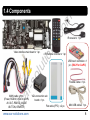
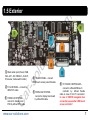
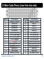
1
co m io ns . Release date : 2011.09.19 Model : CSVI-ESC07-v6.0 / Product code : ESC07-1109-001 ar -s ol ut Video Interface for Cadillac Escalade EXT, ESV, Hybrid, SUV, Cadillac STS, SLS 2007-2012 C Installation Manual www.car-solutions.com [email protected] co m Contents 1. Before installation io ns . 1.1 Precautions 1.2 Main specifications 1.3 System diagram 1.4 Components 1.5 Exterior ol 2.1 Remote controller 2.2 How to use mode switch button 2.3 Main cable pinout 2.4 USB touch screen controller 2.5 OSD menu (On Screen Display) ut 2. Setup -s 3. Installation ar 3.1 Connection to monitors without Compact Flash card 3.2 Connection to monitors with Compact Flash card 8 9 10 11 12 15 22 27 C 4. Troubleshooting 3 4 5 6 7 www.car-solutions.com 2 co m 1.1 Precautions Ignition key should be taken off before starting installation, interface power connection must be the last step in installation. Power cable should be separated during interface connection. There should be no any electronic devices or magnetic pole around installation place. All steps of installation should be performed by well-trained specialist. Dismantling without manufacturer permission cannot be guaranteed (it is prohibited to break attached label on the board.) Check package content when receiving the product. If anything is missing, inform the supplier or manufacturer. According to our sales policy any problems caused by user mistake or carelessness can not be guaranteed. C ar -s ol ut io ns . www.car-solutions.com 3 Inputs - 1 x Video DATA (OEM video input from vehicle main PCB) - 1 x Analog RGBCs (for navigation system RGBCs with C-sync) - 1 x PC RGBHV (for CarPC with 640 x480px resolution, 60 Hz; 800x480px, 60 Hz – with PowerStrip SW) - 1 x REAR-C Input (for external rear view camera source, supports NTSC & PAL auto detection) - 2 x CVBS1, 2 Input (for external video source - DVD, TV, DVB-T; supports NTSC & PAL auto detection) - 1 x Touch In (for OEM touch screen panel) io ns . 1. co m 1.2 Main Specifications ol ut 2. Outputs - 2 x A/VOUT (video/audio output for headrest monitors- CVBS1 mode copy) - 1 x Touch OUT to Navi (OEM touch screen panel connection to Navi connected via RGBCs input or CarPC connected via RGBHV) - 1 x Touch OUT OEM (connection to vehicle main PCB) - 1 x Monitor Output (video output for connection to OEM display LCD panel) ar -s 3. Power - Input power : 7 V DC ~ 18 V DC - Consumption power : 1.8 W @ 12 V C 4. Function - Video input disable: possible to skip each input source by OSD menu settings. - Control by using the remote controller. - Possible to switch between modes by remote mode switch button. www.car-solutions.com 4 co m 1.3 System Diagram io ns . To main PCB of monitor (connect by offered FPC cable) POWER, RGB IN, VGA IN, AV IN, AV OUT, REAR-C, MODE SWITCH BUTTON, IR REMOTE To USB touch controller ADC ut MUX C ar -s ol MCU To LCD panel www.car-solutions.com To OEM touch screen panel To main PCB of monitor (connect by offered FPC cable) 5 io ns . co m 1.4 Components IR Remote controller x 1 pc. ol ut Video interface main board x 1 pc. IR receiver x 1 pc. USB touch controller x 1 pc. (ONLY for CarPC) ar -s Flexible cable x 1 pc. C MAIN cable x 1 pc. (Power, RGB IN, VGA IN, AV IN, AV OUT, REAR-C, MODE BUTTON, REMOTE) www.car-solutions.com VGA connection sub board x 1 pc. Flat cable (FPC) x 2 pc. Mini USB cable x 1 pc. 6 co m 1.5 Exterior ① ⑥ io ns . ⑤ ④ ol ① Main cable input (Power, RGB, ut ② VGA, AV1, AV2, REAR-C, AV OUT, IR receiver, mode switch button ) ④ TO LCD PANEL – connect -s OEM touch screen panel flat cable ② TO LCD PANEL – connect by ar OEM FPC cable ③ FROM CAR SYSTEM – C connect to display main PCB by offered FPC cable www.car-solutions.com ③ ⑤ FROM CAR SYSTEM connect to display main board by offered flat cable ⑥ TO TOUCH CONTROLLER – connect to offered USB touch controller by offered flexible cable in case of Car PC connection. In case of CS9100 navigation box connection use another USB touch screen controller! 7 Buttons Function Power, 0-9, Mute, DMB/DAB NOT USED co m 2.1 Remote Controller io ns . Factory reset – press 2 sec. Source change SCAN Auto config in CarPC mode MENU OSD menu ON/OFF ut SOURCE, MODE CH UP in OSD menu DOWN in OSD menu ol CH PC C DMB LEFT in OSD menu ar VOL RIGHT in OSD menu -s VOL AV CarPC input select OEM picture select AV inputs select (AV1>AV2>AV1…) www.car-solutions.com 8 co m 2.2 How to Use Mode Switch Button If you press the button video source will be changed. ut HOLDING – 3sec. io ns . PRESSING C ar -s ol Hold button for 3 seconds in Original Display Mode to enter Engineer mode. You must open all sources including rear view camera for signal auto check. Follow step by step installation instructions. www.car-solutions.com MODE SWITCH BUTTON 9 Contact # Contact purpose 1 co m 2.3 Main Cable Pinout (view from wire side) Contact purpose POWER ACC +12V DC INPUT 16 POWER GND -12V DC INPUT 2 GND VIDEO OUT 1 17 VIDEO OUT 1 3 GND VIDEO OUT 2 18 VIDEO OUT 2 4 GND VIDEO INPUT 1 19 VIDEO INPUT 1 5 GND VIDEO INPUT 2 20 VIDEO INPUT 2 6 GND REAR CAMERA INPUT 21 REAR CAMERA INPUT 7 (Car PC) VGA INPUT V SYNC 22 (Car PC) VGA INPUT BLUE 8 (Car PC) VGA INPUT H SYNC 23 (Car PC) VGA INPUT GREEN 9 (Car PC) VGA INPUT GND 24 (Car PC) VGA INPUT RED 10 NOT USED 25 (NAVIGATION) RGB INPUT BLUE (NAVIGATION) RGB INPUT CSYNC 26 (NAVIGATION) RGB INPUT GREEN (NAVIGATION) RGB INPUT GND 27 (NAVIGATION) RGB INPUT RED IR RECEIVER DATA 28 MODE BUTTON 12 C 13 ar 11 -s ol ut io ns . Contact # 14 IR RECEIVER GND 29 MODE BUTTON 15 IR RECEIVER +5V DC INPUT 30 REAR CAMERA ACTIVATION www.car-solutions.com 10 ut io ns . co m 2.4 USB Touch Screen Controller C ar -s ol This USB touch screen controller fits for connection only to Car PC with 95, 98, XP, Vista 32bit, 7 32 bit operation systems. You can download drivers for these systems on the product page at our web site. In case of connection to navigation boxes (e.g. CS9100) with WinCE 5.0, WinCE 6.0 operation systems, you will need another touch screen controller. www.car-solutions.com 11 ut io ns . co m 2.5 OSD Menu (On Screen Display) ol PICTURE MENU (image adjustment) ar -s In this menu you can adjust the following image parameters for any video input: C Brightness Contrast Sharpness Saturation – only in AV1, AV2 modes Hue – only in AV1, AV2 modes www.car-solutions.com COLOR MENU (color rendering adjustment) In this menu you can tune chroma level for any video input: Color Temperature Red Green Blue 12 ut io ns . co m 2.5.1 OSD menu (On Screen Display) ol PC SETUP MENU -s In this menu you can adjust following image parameters for VGA input: C ar Horizontal – horizontal position Vertical – vertical positions Phase – image stabilization Frequency – image sharpness Auto Config – automatic adjustment www.car-solutions.com SOURCE CONTROL MENU In this menu you can turn on / off video inputs: Original – OEM image PC – VGA video input Navigation – RGB video input Video 1 – AV1 video input Video 2 – AV2 video input Rearview – input for rear view camera 13 ol ut io ns . co m 2.5.2 OSD menu (On Screen Display) SOURCE CONTROL MENU Car Name – car type selection FirmwareMajor – main firmware version FirmwareMinor – additional firmware version Factory Reset – all settings reset C ar -s continuation Rearview – input for rear view camera. In this menu item you have to select the camera which will be used when reversing. Also you can enable parking guidelines for aftermarket rear view camera. FEATURES MENU www.car-solutions.com 14 ar -s ol ut io ns . co m 3.1 Connection to Monitor without Compact Flash Card C Here you can see monitor from cars of 2006-2009 model years. In these monitors DVD is used for naviga tion maps usage. These discs are inserted in the slot pointed by green arrow in the picture. Once you’ve dismantled monitor you can proceed to interface installation. First of all twist off screws circled in red. www.car-solutions.com 15 -s ol ut io ns . co m 3.1.1 Connection to Monitor without Compact Flash Card C ar Carefully dismantle plastic frame fixed by detents on the edges. Pull off the frame for ~5 cm and turn it with your left hand as indicated by red arrow in the picture. Be careful not to damage anything (we recomm end performing whole procedure with display in horizontal position since the frame holds LCD panel !!!). After turning plastic frame, disconnect flexible flat cable from the board fixed on the frame. First, carefully open lock pins (violet pointers). Then disconnect flat cable. www.car-solutions.com 16 -s ol ut io ns . co m 3.1.2 Connection to Monitor without Compact Flash Card ar Carefully pull on LCD panel for few centimeters and move it down for a couple of centimeters. C Hold LCD panel, open flexible flat cable lock pins in the socket using screwdriver or plastic tool. www.car-solutions.com 17 -s ol ut io ns . co m 3.1.3 Connection to Monitor without Compact Flash Card ar Remove touch screen panel FFC and LCD FFC from the socket. Please, remember contacts position on OEM flexible flat cables. Put LCD panel aside. C Connect offered flat cables to OEM sockets and close lock pins in the sockets. Note! Offered flexible flat cables shall be installed the same side with contacts as removed OEM flexible flat cables. In case of incorrect flat cable installation image will not be displayed. www.car-solutions.com 18 -s ol ut io ns . co m 3.1.4 Connection to Monitor without Compact Flash Card ar Install video interface main board as shown in the picture. Note! Contacts located on the video interface main board back side shall not touch metal frame to which main board is connected. We suggest placing non-conductive material (e.g. thin plastic) between board and metal frame. C Connect wide FFC to «FROM CAR SYSTEM» socket on the board. Connect narrow FFC to «FROM CAR SYSTEM» socket on the board. www.car-solutions.com 19 -s ol ut io ns . co m 3.1.5 Connection to Monitor without Compact Flash Card C ar Connect main cable and USB touch screen controller cable to video interface board and lay them in the monitor framework. We recommend wrapping the cable around with cloth insulating tape to avoid cables chafing by metal ends of the framework. Connect OEM LCD panel wide flat cable to wide «TO LCD PANEL» socket. www.car-solutions.com 20 -s ol ut io ns . co m 3.1.6 Connection to Monitor without Compact Flash Card C ar Connect narrow FFC (often it’s brown) from OEM touch screen panel to narrow «TO LCD PANEL» socket. Carefully attach LCD panel back. In case panel does not fall into place carefully adjust flat cables or video interface main board holders. Assemble monitor in reverse order and install it in its original place. Apply power to video interface and connect all video devices. www.car-solutions.com 21 ar -s ol ut io ns . co m 3.2 Connection to Monitor with Compact Flash Card C Here you can see monitors from cars of 2009-2012 model years. In these monitors CF memory card is used for navigation maps usage. It is inserted in the slot behind blanking plate pointed in the picture by green arrow. Once you’ve dismantled the monitor we can proceed to video interface installation. www.car-solutions.com 22 ar -s ol ut io ns . co m 3.2.1 Connection to Monitor with Compact Flash Card C 1 Twist off screws holding metal plates on both sides. 2 Remove monitor metal upper cover. www.car-solutions.com 23 ar -s ol ut io ns . co m 3.2.2 Connection to Monitor with Compact Flash Card C 3 Carefully dismantle plastic frame holding LCD panel. 4 Be careful not to damage LCD panel and touch screen panel flexible flat cables. Disconnect FFCs from monitor main board. www.car-solutions.com 24 -s ol ut io ns . co m 3.2.3 Connection to Monitor with Compact Flash Card ar 5 Connect display main board and «FROM CAR SYSTEM» video interface socket by wide flexible flat cable. Do the same with narrow flat cable. C 6 Fix video interface main board as shown in the picture and connect main cable and USB touch screen controller cable. We recommend wrapping the cable around with cloth insulating tape to avoid cables chafing by metal ends of the framework. www.car-solutions.com 25 -s ol ut io ns . co m 3.2.4 Connection to Monitor with Compact Flash Card ar 7 Connect LCD panel OEM wide flat cable to wide «TO LCD PANEL» socket of video interface. Do the same with touch screen panel narrow flat cable. C Assemble monitor in reverse order and install it in its original place. Apply power to video interface and connect all video devices. www.car-solutions.com 26 co m 4 Troubleshooting Q. I cannot switch A/V sources. A. Check main cable connection. Check whether main cable and/or mode switch remote button cable are not damaged. Check IR receiver connection. io ns . Q. Black screen is displayed after connection. A. Check flat cables connection. Make sure that main cable is connected. Using tester check whether 12 V are supplied to certain contacts of main cable (see page 10). Check and activate corresponding video inputs in OSD menu (see page 13). Q. Displayed image color and brightness are incorrect (too dim or too bright). A. Try to adjust brightness, contrast and colors in the relative OSD menu items (see page 12) . ut Q. Image from rear view camera connected via REAR-C input is not displayed when reversing. A. Check REAR-V wire connection (see page 10) to rear lamps 12 V line. -s ol Q. Black screen blinks when changing modes. A. Check and activate corresponding video inputs in OSD menu (see page 13). If all video inputs are activated in OSD menu they will be switched in the following cyclic order: OEM->VGA->RGB->AV1->AV2. ar Q. OEM image is not displayed. A. Check flat cables connection. Check and enable corresponding video inputs in OSD menu (see page 13). If the problem still exist inform technical support. C Q. Screen is white, no images are displayed. A. Check flat cables connection. If the problem still exist inform technical support. www.car-solutions.com 27