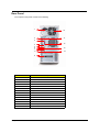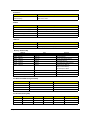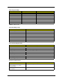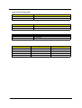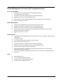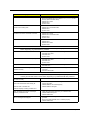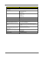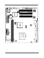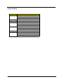
1
Power SP
Service Guide
Service guide files and updates are available
on the AIPG/CSD web; for more information,
please refer to http://csd.acer.com.tw
PRINTED IN TAIWAN
P/N: VD.PSPVF.001
Revision History
Please refer to the table below for the updates made on Acer Power SP service guide.
Date
II
Chapter
Updates
Copyright
Copyright © 2003 by Acer Incorporated. All rights reserved. No part of this publication may be reproduced,
transmitted, transcribed, stored in a retrieval system, or translated into any language or computer language, in
any form or by any means, electronic, mechanical, magnetic, optical, chemical, manual or otherwise, without
the prior written permission of Acer Incorporated.
Disclaimer
The information in this guide is subject to change without notice.
Acer Incorporated makes no representations or warranties, either expressed or implied, with respect to the
contents hereof and specifically disclaims any warranties of merchantability or fitness for any particular
purpose. Any Acer Incorporated software described in this manual is sold or licensed "as is". Should the
programs prove defective following their purchase, the buyer (and not Acer Incorporated, its distributor, or its
dealer) assumes the entire cost of all necessary servicing, repair, and any incidental or consequential
damages resulting from any defect in the software.
Acer is a registered trademark of Acer Corporation.
Intel is a registered trademark of Intel Corporation.
Pentium and Pentium II/III are trademarks of Intel Corporation.
Other brand and product names are trademarks and/or registered trademarks of their respective holders.
III
Conventions
The following conventions are used in this manual:
IV
Screen messages
Denotes actual messages that appear
on screen.
NOTE
Gives bits and pieces of additional
information related to the current
topic.
WARNING
Alerts you to any damage that might
result from doing or not doing specific
actions.
CAUTION
Gives precautionary measures to
avoid possible hardware or software
problems.
IMPORTANT
Reminds you to do specific actions
relevant to the accomplishment of
procedures.
Preface
Before using this information and the product it supports, please read the following general information.
1.
This Service Guide provides you with all technical information relating to the BASIC CONFIGURATION
decided for Acer's "global" product offering. To better fit local market requirements and enhance product
competitiveness, your regional office MAY have decided to extend the functionality of a machine (e.g.
add-on card, modem, or extra memory capability). These LOCALIZED FEATURES will NOT be covered
in this generic service guide. In such cases, please contact your regional offices or the responsible
personnel/channel to provide you with further technical details.
2.
Please note WHEN ORDERING FRU PARTS, that you should check the most up-to-date information
available on your regional web or channel. If, for whatever reason, a part number change is made, it will
not be noted in the printed Service Guide. For ACER-AUTHORIZED SERVICE PROVIDERS, your Acer
office may have a DIFFERENT part number code to those given in the FRU list of this printed Service
Guide. You MUST use the list provided by your regional Acer office to order FRU parts for repair and
service of customer machines.
V
VI
Chapter 1
System Specifications
Overview
Acer Power SP supports Intel Pentium 4 Northwood based micro-ATX, IBM PC/AT compatible system with
PCI/AGP bus.
NOTE: CPU frequency: up to 2.6GHz.
Chapter 1
1
Features & Specifications
CPU
T
Intel Pentium 4 Willamette/Northwood, Celeron
T
Front Side Bus: 400MHz
T
Frequency: up to 2.6GHz
Chipset
T
Brookdale-GL
T
ICH: Intel ICH4.
T
SST 49LF002 FWH (2MB)
Memory
T
Two DIMM sockets
T
DDR 200/266
T
Capacity: 128MB ~ 1GB (please refer to the AVL list for compatibility).
T
Winbond 49V002FAP FWH (2MB)
T
Award BIOS code
T
ACPI supported, default S3
BIOS
Super I/O
T
Winbond W83627HF LPC super I/O with Hardware monitor supported
T
ICH4
T
Dual PCI Bus master enhanced IDE
T
Ultra DMA 33/66/100 supported
T
1.44/2.88 MB FDD
RTC
IDE
FDD
Graphics
T
On-die VGA
Audio
T
On-board (RealTek ALC201A AC’97 CODEC)
T
RealTek RTL8100BL integrated LAN with support WOL
T
USB 2.0 Host Controller
LAN
USB
2
Chapter 1
Expansion slots
T
3 PCI slot (PCI 2.2)
Board size
T
Micro-ATX, 4 Layers
Industrial Standard
Chapter 1
T
Windows Hardware Compatibility Labs
T
ACPI 1.0b
T
PCI 2.2
T
PC2001 compliance
T
Wired for Management 2.0
T
Suspend to RAM
3
Front Panel
The computer’s front panel consists of the following:
1
2
3
4
5
6
Label
4
Description
1
Optical Drive‘
2
Floppy Drive
3
Power Button
4
USB Ports
5
Microphone Jack
6
Speaker/Headphone Jack
Chapter 1
Rear Panel
The computer’s rear panel consists of the following:
1
10
2
11
3
12
4
5
6
7
8
13
14
9
Label
Description
1
Power cord socket
2
PS/2 keyboard port
3
Serial connector
4
Monitor connector
5
Headphone jack
6
Speaker Jack
7
Microphone Jack
8
USB Connector
9
PCI card slot
10
Fan aperture
11
PS/2 mouse connector
12
Printer connector
13
Game/MIDI port
14
RJ-45 ethernet connector
Chapter 1
5
6
Chapter 1
Hardware Specifications and Configurations
Processor
Item
Specification
Type
Pentium 4
Socket
478
Speed
1.8G~2.6G+
Minimum operating speed
0 MHz (If Stop CPU Clock in Sleep State in BIOS Setup is set to
Enabled.)
Voltage
Processor voltage can be detected by the system without setting any
jumper.
BIOS
Item
Specification
BIOS code programmer
Award
BIOS version
v6.0
BIOS ROM type
Flash ROM
BIOS ROM size
2MB
BIOS ROM package
32-pin DIP package
Support protocol
PCI 2.2, APM1.2, DMI 2.00.1, E-IDE, ACPI 1.0, ESCD 1.03, ANSI
ATA 3.0, PnP 1a, Bootable CD-ROM 1.0, ATAPI
Boot from CD-ROM feature
Yes
Support to LS-120 drive
No
Support to BIOS boot block feature
No
NOTE: The BIOS can be overwritten/upgraded by using the flash utility.
BIOS Hotkey List
Hotkey
c
Chapter 1
Function
Enter BIOS Setup Utility
Description
Press while the system is booting to enter
BIOS Setup Utility.
7
This section has two table lists, system memory specification and the possible combinations of memory
module.
System Memory
Item
Specification
Memory socket number
2 sockets (4 banks)
Support memory size per socket
64MB / 128MB / 256MB/ 512MB
Support maximum memory size
1G x2
Support memory type
DDR SDRAM
Support memory speed
266MHz (PC2001)
Support memory voltage
2.5 V
Support memory module package
184-pin DIMM
Support to parity check feature
Yes
Support to Error Correction Code (ECC) feature
Yes
Memory module combinations
You can install memory modules in any combination as long as
they match the above specifications.
Memory Combinations
Slot
Memory Module
Total Memory
Slot 1
64, 128, 256, 512MB, 1G
64MB~1G
Slot 2
64, 128, 256, 512MB, 1G
64MB~1G
Maximum System Memory Supported
64MB~2G
Cache Memory
Item
Specification
First-Level Cache Configurations
Cache function control
Enable/Disable by BIOS Setup
Second-Level Cache Configurations
L2 Cache RAM type
PBSRAM
L2 Cache RAM size
256-KB
L2 Cache RAM speed
One-half the processor core clock frequency
L2 Cache RAM voltage
L2 Cache function control
Enable/Disable by BIOS Setup
L2 Cache scheme
Fixed in write-back
Video Memory
Item
Memory size
Specification
8 MB or above
This section has two table lists, the video interface specification and its supported display modes.
Video Interface
Item
8
Specification
Video controller
Intel 845GE
Video controller resident bus
AGP bus
Chapter 1
Video Interface
Item
Specification
Video interface support
Video YUV texture in all texture formats
H/W DVD accelerator
Display Screen Resolution
Refresh Rate (Hz)
Hor. Scan (KHz)
Pixel Clock (MHz)
640x480
60
31.5
25.2
640x480
72
37.4
32.0
640x480
75
37.5
31.5
640x480
85
43.3
36.0
640x480
120
63.7
55.0
800x600
56
35.2
36.0
800x600
60
37.8
39.9
800x600
72
48.0
50.0
800x600
75
46.9
49.5
800x600
85
53.7
56.2
800x600
100
62.5
67.5
800x600
120
76.1
81.0
800x600
160
101.9
110.0
1024x768
70
56.5
75.0
1024x768
75
60.0
78.8
1024x768
100
79.0
110.0
1280x1024
43
50.0
80.0
1280x1024
60
64.0
110.0
1280x1024
85
91.2
157.5
1600x1200
60
76.2
156.0
1600x1200
85
106.2
229.5
Audio Interface
Item
Specification
Audio controller
ICH4
Audio controller resident bus
AC’97
Audio function control
Enable/disable by BIOS Setup
Mono or stereo
Stereo
Resolution
20 bits
Compatibility
Sound Blaster Pro/16 compatible
Mixed digital and analog high performance chip
Enhanced stereo full duplex operation
High performance audio accelerator and AC’97 support
Full native DOS games compatibility
Virtual FM enhances audio experience through real-time FM-to-Wavetable
conversion
MPU-401(UART mode) interface for wavetable synthesizers and MIDI
devices
Integrated dual game port
Meets AC’97and WHQL specifications
Music synthesizer
Chapter 1
Yes, internal FM synthesizer
9
Audio Interface
Item
Specification
Sampling rate
48 KHz (max.)
MPU-401 UART support
Yes
Microphone jack
Supported
Headphone jack
Supported
IDE Interface
Item
Specification
IDE controller
Intel ICH4
IDE controller resident bus
PCI bus
Number of IDE channel
2
Support IDE interface
E-IDE (up to PIO mode-4 and Ultra DMA 33/66), ANSIS ATA rev.3.0 ATAPI
Support bootable CD-ROM
Yes
Floppy disk drive Interface
Item
Specification
Floppy disk drive controller
Intel ICH4
Floppy disk drive controller resident bus
ISA bus
Support FDD format
360KB, 720KB, 1.2MB, 1.44MB, 2.88MB
Parallel Port
Item
Parallel port controller
Specification
Intel ICH4
Parallel port controller resident bus
ISA bus
Number of parallel ports
1
Support ECP/EPP
SPP / Bi-directional / ECP / EPP
Connector type
25-pin D-type female connector
Parallel port function control
Enable/disable by BIOS Setup
Optional ECP DMA channel
DMA channel 1
(in BIOS Setup)
DMA channel 3
Optional parallel port I/O address
378h
(via BIOS Setup)
278h
Optional parallel port IRQ
IRQ5
(via BIOS Setup)
IRQ7
Serial Port
Item
10
Specification
Serial port controller
Intel ICH4
Serial port controller resident bus
ISA bus
Number of serial port
2
16550 UART support
Yes
Connector type
9-pin D-type female connector
Optional serial port I/O address
COM1: 2F8h, 3E8h, 2E8h
(via BIOS Setup)
COM2: 3E8h, 3F8h, 2F8h
Chapter 1
Serial Port
Item
Specification
Optional serial port IRQ
COM1: IRQ 3, and 4
(via BIOS Setup)
COM2: IRQ 4, and 3
Modem
Item
Specification
Fax modem data baud rate (bps)
V.17 12K/1.44K
Data modem data baud rate (bps)
V.90 32K to 56K (received only)
Voice modem
V.253
Modem connector type
RJ11
Full duplex
Yes
USB Port
Item
Specification
Universal HCI
USB 2.0
USB Class
Support legacy keyboard for legacy mode
Memory Address Map
Address
Size
Function
000000 - 07FFFF
512KBytes
Host Memory
080000 - 09FFFF
128KBytes
Host/PCI Memory
0A0000 - 0BFFFF
128KBytes
PCI/ISA Video Buffer Memory
0C0000 - 0C7FFF
32KBytes
Video BIOS Memory
0C8000 - 0DFFFF
96Kbytes
ISA Card BIOS & Buffer Memory
0E0000 - 0EFFFF
64Kbytes
BIOS Extension Memory
Setup and Post Memory
PCI Development BIOS
0F0000 - 0FFFFF
64Kbytes
System BIOS Memory
100000 - UPPER LIMIT
Main Memory
UPPER LIMIT - 4GBytes
PCI Memory
PCI INTx# and IDSEL Assignment Map
PCI INTx #
PCI Devices
Device IDSEL: ADxx
INTA#
ADIMM-slot
N
INTB#
PCI-Slot1
AD20
INTC#
PCI-Slot2
AD22
INTD#
PCI-Slot3
AD24
PCI Slot IRQ Routing Map
PCI INTX#
INTA
INTB
INTC
INTD
Bus Mastering
PCI slot 1
Route 4
Route 1
Route 2
Route 3
Enabled
PCI slot 2
Route 3
Route 4
Route 1
Route 2
Enabled
PCI slot 3
Route 2
Route 3
Route 4
Route 1
Enabled
Chapter 1
11
I/O Address Map
Hex Range
Devices
000-01F
DMA Controller-1
020-021
Interrupt Controller-1
040-043
System Timer
060-060
Keyboard Controller 8742
061-061
System Speaker
070-071
CMOS RAM Address and Real Time Clock
080-08F
DMA Page Register
0A0-0A1
Interrupt Controller-2
0C0-0DF
DMA Controller-2
0F0-0FF
Math Co-Processor
170-177
Secondary IDE
1F0-1F7
Primary IDE
278-27F
Parallel Printer Port 2
2F8-2FF
Serial Asynchronous Port 2
378-37F
Parallel Printer Port 1
3F0-3F5
Floppy Disk Controller
3F6-3F6
Secondary IDE
3F7-3F7
Primary IDE
3F8-3FF
Serial Asynchronous Port 1
0CF8
Configuration Address Register
0CFC
Configuration Data Register
778-77A
Parallel Printer Port 1
IRQ Assignment Map
IRQx
IRQ0
System Devices
Timer
Add-On-Card Devices
N
IRQ1
Keyboard
N
IRQ2
Cascade Interrupt Control
N
IRQ3
Serial Alternate
Reserved
IRQ4
Serial Primary
Reserved
IRQ5
MPU-401(Alternate)
Reserved
IRQ6
Floppy Disk
Reserved
IRQ7
Parallel Port
Reserved
IRQ8
Real Time Clock
N
IRQ9
N
Reserved
IRQ10
N
Reserved
IRQ11
N
Reserved
IRQ12
PS/2 Mouse
Reserved
IRQ13
Math Coprocessor Exception
N
IRQ14
Primary IDE
Reserved
IRQ15
Secondary IDE
Reserved
NOTE: N - Not be used
12
Chapter 1
DRQ Assignment Map
DRQx
DRQ0
System Devices
N
Add-On-Card Devices
Reserved
DRQ1
N
Reserved
DRQ2
FDD
N
DRQ3
N
Reserved
DRQ4
Cascade
N
DRQ5
N
Reserved
DRQ6
N
Reserved
DRQ7
N
Reserved
NOTE: N - Not be used
Main Board Major Chips
Item
Controller
System core logic
Intel 845GE/ICH4
Video controller
Intel 845GE
Super I/O controller
LPC47M192
Audio controller
Intel 845GE
LAN controller
Intel 845GE
HDD controller
Built in ICH4
Keyboard controller
Built in ICH4
RTC
Built in ICH4
Environmental Requirements
Item
Specifications
Temperature
Operating
+5 ~ +35°C
Non-operating
-20 ~ +60°C (Storage package)
Humidity
Operating
15% to 80% RH
Non-operating
20% to 90% RH
Vibration
Operating (unpacked)
5-500Hz, 2.20G
Non-operating (packed)
5-500Hz, 1.09G
Mechanical Specifications
Item
Weight
Specification
Varied by local configuration
One 3 ½ FDD and one 3.5 HDD
(without packing)
Dimensions
N/A
(main footprint)
Chapter 1
13
Switching Power Supply 200W
Input Frequency
Frequency Variation Range
50MHz
47MHz to 53MHz
60MHz
57MHz to 63MHz
Input Voltage
Variation Range
100 - 120 VRMS
90 - 132 VRMS
200 - 240 VRMS
180 - 264 VRMS
Input Current
Measuring Range
4A
90 -132 VRMS
2A
180 - 264 VRMS
NOTE: Measure at line input 90 VRMS and maximum load condition.
Output Requirements
Regulation
Current Rating
+5V
+-5%
15A
+12V
+-5%
3A
-12V
+-10%
0.3A
+3.3V
+-4%
12A
+5Vaux
+-5%
3A
NOTE: APSP is equipped with a 200W power supply.
14
Chapter 1
Power Management Function (ACPI support function)
Device Standby Mode
T
Independent power management timer for hard disk drive devices
(0-15 minutes, time step=1 minute).
T
Hard disk drive goes into Standby mode (for ATA standard interface).
T
Disable V-sync to control the VESA DPMS monitor.
T
Resume method: device activated (Keyboard for DOS, keyboard & mouse for Windows).
T
Resume recovery time: 3-5 sec.
Global Standby Mode
T
Global power management timer (2-120 minutes, time step=10 minute).
T
Hard disk drive goes into Standby mode (for ATA standard interface).
T
Disable H-sync and V-sync signals to control the VESA DPMS monitor.
T
Resume method: Return to original state by pushing external switch button, modem ring in,
keyboard and mouse for APM mode.
T
Resume recovery time: 7-10 sec.
Suspend Mode
T
Independent power management timer (2-120 minutes, time step=10 minutes) or pushing external
switch button.
T
CPU goes into SMM.
T
CPU asserts STPCLK# and goes into the Stop Grant State.
T
LED on the panel turns amber colour.
T
Hard disk drive goes into SLEEP mode (for ATA standard interface).
T
Disable H-sync and V-sync signals to control the VESA DPMS monitor.
T
Ultra I/O and VGA chip go into power saving mode.
T
Resume method: Return to original state by pushing external switch button, modem ring in,
keyboard and mouse for APM mode.
T
Return to original state by pushing external switch button, modem ring in and USB keyboard for
ACPI mode.
T
ACPI specification 1.0.
T
S0, S1, S3 and S5 sleep state support.
T
On board device power management support.
T
On board device configuration support.
ACPI
Chapter 1
15
16
Chapter 1
Chapter 2
System Utilities
Most systems are already configured by the manufacturer or the dealer. There is no need to run
Setup when starting the computer unless you get a Run Setup message.
The Setup program loads configuration values into the battery-backed nonvolatile memory called CMOS RAM.
This memory area is not part of the system RAM.
NOTE: If you repeatedly receive Run Setup messages, the battery may be bad/flat. In this case, the system
cannot retain configuration values in CMOS.
Before you run Setup, make sure that you have saved all open files. The system reboots immediately after
you exit Setup.
Chapter 2
17
Entering Setup
Power on the computer and the system will start POST (Power On Self Test) process. When the message of
“Press DEL to enter SETUP” appears on the screen, press c to enter the setup menu.
NOTE: If the message disappears before you respond and you still wish to enter Setup, restart the system by
turning it OFF and On. You may also restart the system by simultaneously pressing [Ctrl+Alt+Delete].
The Setup Utility main menu then appears:
18
Chapter 2
The command line at the bottom of the menu tells you how to move within a screen and from one screen to
another.
T
To select an option, move the highlight bar by pressing
T
To change a parameter setting, press
T
Press
to return to the main menu. If you are already in the main menu, press
exit Setup.
or
or
then press
.
until the desired setting is found.
again to
The parameters on the screens show default values. These values may not be the same as those in your
system.
The grayed items on the screens have fixed settings and are not user-configurable.
NOTE: Due to the application of a new version of BIOS Setup program, you may find the BIOS menu is largely
different from the former models. However, you will soon find out that this version is much more
compact than the former ones.
Chapter 2
19
Product Information
The screen below appears if you select Product Information from the main menu:
The Product Information menu contains general data about the system, such as the product name, serial
number, BIOS version, etc. These information is necessary for troubleshooting (may be required when asking
for technical support).
20
Chapter 2
The following table describes the parameters found in this menu:
Parameter
Description
Product Name
Displays the model name of your system.
System S/N
Displays your system’s serial number.
Main Board ID
Displays the main board’s identification number.
Main Board S/N
Displays your main board’s serial number.
System BIOS Version
Specifies the version of your BIOS utility.
SMBIOS version
The System Management Interface (SM) BIOS allows you to check your system
hardware components without actually opening your system. Hardware checking
is done via software during start up. This parameter specifies the version of the
SMBIOS utility installed in your system.
System BIOS ID
Specifies the version ID of the BIOS utility.
BIOS Release Date
Displays the release date of the BIOS utility.
Chapter 2
21
Standard CMOS Features
Select Standard CMOS Features from the main menu to configure some basic parameters in your system.
The following screen shows the Standard CMOS Features menu:
The following table describes the parameters found in this menu. Settings in boldface are the default and
suggested settings.
Parameter
Date
Description
Lets you set the date following the weekdaymonth-day-year format
Options
Weekday: Sun, Mon...Sat
Month: Jan, Feb...Dec.
Day: 1 to 30
Year: 1980 to 2079
Time
Lets you set the time following the hour-minutesecond format
Hour: 0 to 23
Allows you to configure the hard disk drive
connected to the master port of IDE channel 1.
IDE Device Model Number:
None
Minute: 0 to 59
Second: 0 to 59
IDE Primary Channel Master
To enter the IDE Primary Master setup, press
[Enter].
The IDE CD-ROM is always automatically
detected.
IDE Primary Channel Slave
Allows you to configure the hard disk drive
connected to the slave port of IDE channel 1.
IDE Device Model Number:
None
To enter the IDE Primary Slave setup, press
[Enter].
The IDE CD-ROM is always automatically
detected.
22
Chapter 2
Parameter
IDE Secondary Channel Master
Description
Allows you to configure the hard disk drive
connected to the master port of IDE channel 2.
Options
IDE Device Model Number:
None
To enter the IDE Secondary Master setup, press
[Enter].
The IDE CD-ROM is always automatically
detected.
IDE Secondary Channel Slave
Allows you to configure the hard disk drive
connected to the slave port of IDE channel 2.
IDE Device Model Number:
None
To enter the IDE Secondary Slave setup, press
[Enter].
The IDE CD-ROM is always automatically
detected.
Drive A
Allows you to configure your floppy drive A.
1.44 MB, 3.5-inch
None
360 KB, 5.25-inch
1.2 MB, 5.25-inch
720 KB, 3.5-inch
2.88 MB, 3.5-inch
Drive B
Allows you to configure your floppy drive B.
1.44 MB, 3.5-inch
None
360 KB, 5.25-inch
1.2 MB, 5.25-inch
720 KB, 3.5-inch
2.88 MB, 3.5-inch
Video
Halt On
This item specifies the type of video card in use.
The default setting is VGA/EGA. Since current
PCs use VGA only, this function is almost
useless and may be disregarded in the future.
VGA/EGA
This parameter enables you to control the
system stops in case of Power On Self Test
errors (POST).
All Errors
CGA40
CGA80
Mono
No Errors
All but Keyboard
All but Diskette
All by Disk/Key
Base Memory
Refers to the option of memory that is available
to standard DOS programs. DOS systems have
an address space od 1MB, but the top 384KB
(called high memory) is reserved for system use.
This leaves 640 KB of conventional memory.
Everything above 1MB is either extended or
extended memory.
Extended Memory
Memory above and beyond the standard 1MB of
base memory that DOS supports. Extended
memory is only available in PCs with an Intel
80286 or later microprocessor. Extended
memory is not configured in any special manner
and is therefore unavailable to most DOS
programs. However, MS Windows and OS/2 can
use extended memory.
Total Memory
Total based and extended memory, and I/O ROM
384KB available to the system.
Chapter 2
23
Advanced BIOS Features
The following screen shows the Advanced BIOS Features:
The following table describes the parameters found in this menu. Settings in boldface are the default and
suggested settings.
Parameter
Virus Warning
Quick Power On Self Test
Description
Options
Allows you to set the virus warning feature for
IDE Hard Disk boot sector protection. If the
function is enabled and any attempt to write
data into this area is made, BIOS will display a
warning message on screen and beep.
Enabled
This parameter speeds up POST by skipping
some items that are normally checked.
Enabled
The items allow you to set the sequence of boot
device where BIOS attempts to load the disk
operating system.
Floppy, LS120, HDD-0, SCSI,
CDROM, HDD-1, HDD-2, HDD-3, ZIP,
LAN, Disabled (Disable this sequence
).
Disabled
Disabled
Hard Disk Boot Priority
First/Second/Third Boot
Device
The sequence following the order of
HDD, Floppy and CD-ROM is
recommended.
Boot Other Device
24
This parameter allows you to specify the system
boot up search sequence.
Enabled
Swap Floppy Drive
Setting to Enabled will swap floppy drive a: and
b:.
Enabled
Boot Up Floppy Seek
Setting to Enabled will make BIOS seek floppy
drive a: before booting the system.
Enabled
Disabled
Disabled
Disabled
Chapter 2
Parameter
Description
Options
Sets the NumLock status when the system is
powered on. Setting to On will turn on the
NumLock key when the system is powered on.
Setting to Off will allows users to use the arrow
keys on the numeric keypad.
On
This item is to set the Gate A20 status. A20
refers to the first 64KB of extended memory.
When the default value Fast is selected, the
Gate A20 is controlled by port 92 or chipset
specific method resulting in faster system
performance. When Normal is selected, A20 is
controlled by a keyboard controller or chipset
hardware.
Fast
This item is used to enable or disable the
typematic rate setting including Typematic Rate
and Typematic Delay.
Enabled
Typematic Rate
After Typematic Rate Setting is enabled, this
item allows you to set the rate (characters/
second) at which at keys are accelerated.
Settings: 6,8,10,12,15,20,24 and 30.
Typematic Delay
This item allows you to select the delay
between when the key was first pressed and
when the acceleration begins
Settings: 250, 500, 750 and 1000.
Security Option
Specifies the type of BIOS password protection
that is implemented. Setup means that the
password prompt appears only when end users
try to run Setup. System means that a
password prompt appears every time when the
computer is powered on or when end users try
to run Setup.
Setup
This field is used to enable or disable the APIC
(Advanced Programmable Interrupt Controller).
Due to compliance with PC2001 design guide,
the system is able to run in APIC mode.
Enabling APIC mode will expand available IRQ
resources from the system.
Enabled
Boot Up NumLock Status
Gate A20 Option
Typematic Rate Setting
APIC Mode
MPS Version Control for OS
Chapter 2
Off
Normal
Disabled
System
Disabled
This field allows you to select which MPS (Multi- 1.4
Processor Specification) version to be used for 1.1
the operating system. You need to select the
MPS version supported by your operating
system. To find out which version to use,
consult the vendor of your operating system.
25
Advanced Chipset Features
The advanced chipset features setup option is used to change the values of the chipset registers. These
registers control most of the system options in the computer.
NOTE: Change these settings only if you are familiar with the chipset.
26
Chapter 2
Integrated Peripherals
The following table describes each Integrated Peripherals parameters. Settings in boldface are the default
and suggested values.
Parameter
Description
Options
Internal PCI/IDE
This setting enables or disables the internal
primary and secondary PCI & IDE controllers.
Both, Disabled, Primary,
Secondary
IDE Primary Master PIO
Setting these items to “Auto” activates the HDD
speed auto-detect function. The PIO mode
specifies the data transfer rate of the HDD. For
example, mode 0 data transfer rate is 3.3MB/s,
mode 1 is 5.2 MB/s, mode 2 is 8.3MB/s, mode 3
is 11.1 MB/s and mode 4 is 16.6MB/s. If your
hard disk performance becomes unstable, you
may manually try the slower mode.
Auto, mode 1, mode 2, mode 3
and mode 4
IDE Primary Slave PIO
IDE Secondary Master PIO
IDE Secondary Slave PIO
Primary Master UltraDMA
These items allow you to set the Ultra DMA 33/
66/100 mode supported by the hard disk drive
Secondary Master UltraDMA connected to your primary and secondary IDE
connectors.
Secondary Slave UltraDMA
Auto
Primary Salve UltraDMA
Disables
IDE Burst Mode
This allows your hard disk controller to use the
fast block mode to transfer data to and from the
hard disk drive.
Enabled
Enabling the on-die AC97 Auto if no add-on PCI
audio device.
Auto
For SiS650 chipset, the system shares memory
to the onboard VGA card. This setting controls
the exact memory size shared to the VGA card.
4, 8, 16, 32, 64MB
AC97 Audio
System Share Memory Size
Chapter 2
Disabled
Disabled
27
Parameter
Description
Options
USB Controller
This item is used to enable or disable the on-chip
USB.
Enabled
USB Keyboard Support
This item lets you enable or disable the USB
keyboard driver within the onboard BIOS. The
keyboard driver simulates legacy keyboard
command and lets you use a USB keyboard
during POST or after boot if you do not have a
USB driver in the operating system.
Enabled
This item lets you enable or disable the USB
mouse driver within the onboard BIOS. The
keyboard driver simulates legacy mouse
command and lets you use a USB mouse during
POST or after boot if you do not have a USB
driver in the operating system.
Enabled
To enable or disable the onboard LAN controller
Enabled
USB Mouse Support
Onboard LAN function
Disabled
Disabled
Disabled
Disabled
Onboard LAN Boot ROM
This setting determines whether or not to
activate the boot ROM of the onboard LAN chip.
Enabled
IDE HDD Block Mode
Block mode is also called block transfer, multiple
commands or multiple sector read/write. If your
IDE hard drive supports block mode (most new
drives do), select “Enabled” for automatic
detection of the optimal number of block read/
write per sector the drive can support.
Enabled
Setting this parameter to “Enable” allows you to
connect your floppy disk drives to the onboard
floppy disk connector instead of a separate
controller card. Change the setting to “Disabled”
if you want to use a separate controller card.
Enabled
Onboard FDC Controller
28
Disabled
Disabled
Disabled
Chapter 2
Chapter 2
29
Power Management Setup
The Power Management menu lets you configure your system to most effectively save energy while operating
in a manner consistent with your own style of computer use.
The following screen shows the Power Management parameters and their default settings:
The following table describes the parameters found in this menu. Settings in boldface are the default and
suggested settings.
Parameter
ACPI Function
ACPI Suspend Type
30
Description
Options
This item is to activate the ACPI (Advanced
Configuration and Power Management Interface)
Function. If your operating system is ACPIaware, such as Windows 98SE/2000/Me, select
Enabled.
Enabled
This item specifies the power saving modes for
ACPI function. S1(POS): The S1 sleep mode is
a low power state. In this state, no system
context (CPU or chipset) is lost and hardware
maintains all system context. S3 (STR): The S3
sleep mode is s power-down state in which
power is supplied only to essential components
such as main memory and wake-capable
devices and all system context is saved to main
memory. The information stored in memory will
be used to restore the PC to the previous state
when an wake-up event occurs. S1&S3: Both S1
and S3 will be adopted.
S3
Disabled
S1
S1&S3
Chapter 2
Parameter
Description
Options
This item is to control the mode in which the
monitor will shut down.
Always On
Always On: Always keep the monitor on.
Suspend --> Off: During suspend mode, the
monitor will shut down. Susp, Stby --> During
suspend or standby mode, the monitor will shut
down. All Modes --> Off: The monitor is turned
off during doze, standby or suspend mode.
Susp, Stby --> Off
This item determines the manner in which the
monitor is blanked.
V/H SYNC+Blank
V/H SYNC+Blank: This selection will cause the
system to turn off the vertical and horizontal
synchronization ports and write blanks to the
video buffer. Blank Screen: This option only
write blanks to the video buffer. DPMS
Supported: Initial display power management
signaling.
DPMS Supported
Modem Use IRQ
This setting names the interrupt request (IRQ)
line assigned to the modem (if any) on your
system. Activity of selected IRQ always
awakens the system.
3, 4, 5, 7, 9, 10, 11, AUTO.
HDD Power Down
If HDD activity is not detected for the length of
time specified in this field, the hard disk drive will
be powered down while all other devices remain
active.
Disabled
This feature allows users to configure the power
button function.
Instant Off: The power button
functions as a normal poweron/-off button.
Video Off Option
Video Off Method
Soft-off by PWR-BTTN
Suspend Off
All Modes
Blank Screen
1~15 Mins
Delay 4 Sec.: When you press
the power button, the
computer enters the suspend/
sleep mode, but if the button is
pressed for more than four
seconds, the computer will be
turned off.
After PC Power Lost
This item specifies when your system reboot
after a power failure or interrupt occurs.
Power Off
Power On
Last State
Power On by Ring
When enabled, any fax/modem activity wakes up
the system from suspend mode.
Disabled
Wake-Up by PCI Card
Use PCI Wake-up system. PCI must meet PCI
2.2 specification.
Disabled
Resume by Alarm
Use this option to set the date and time for your
computer to boot up.
Disabled
Date (of month) Alarm* - Indicate the month for
system to boot up. Set it to 0 if you want to boot
up everyday.
*Set Resume by Alarm to
Enable, then press “Enter” to
show the range of Date and
Time Alarm.
Time (hh:mm:ss) Alarm* - Indicate the hour,
minute and second for system to boot up.
Chapter 2
Enabled
Enabled
Enabled
31
PnP/PCI Configuration
The following table describes the parameters found in this menu. Settings in boldface are the default and
suggested settings.
Parameter
Reset Configuration Data
Resources Controlled By
Description
Options
Selecting “Enabled” to reset Extended System
Configuration Data (ESCD) only if you installed
a new add-on and the system reconfiguration
has caused such a serious conflict that the
operating system can not boot. Otherwise, you
should leave it unchanged.
Disabled
This BIOS can automatically configure all of the
boot and Plug and Play compatible devices.
You can also set it as Manual and go into each
of the sub menu to choose specific resources.
Auto (ESCD)
Enabled
Manual
IRQ Resources
The items are adjustable only when “Resources PCI Device
Controlled By” is set to Manual. By pressing
Reserved
“Enter” to access the sub menu.
PCI/VGA Palette Snoop
Disabled - Data read or written by the CPU is
only directed to the PCI VGA device’s palette
registers.
Enabled - Data read or written by the CPU is
directed to both the PCI VGA device’s palette
registers and the ISA VGA device’s palette
registers, permitting the palette registers of both
VGA devices to be identical.
Disabled
Enabled
*If any ISA bus adapter in the
system requires VGA Palette
snooping, the setting must be set
to “Enabled”.
NOTE: It is strongly recommended that only experienced users should make any changes to the default
settings.
32
Chapter 2
PC Health Status
The following table describes the parameters found in this menu:
Parameter
Description
Shutdown Temperature
This option is for setting the shutdown temperature
level for the processor. When the processor
reaches the temperature you set, the ACPI-aware
system will be shut down.
Current System/CPU
Temperature, CPU/
System fan, Vcore, ect.
These items display the current status of all of the
mainboard hardware devices/components such as
CPU voltages, temperatures and all fans’ speeds.
Chapter 2
Options
33
Frequency Control
The following table describes the parameters found in this menu. Settings in boldface are the default and
suggested settings.
Parameter
Options
CPU Clock Ratio
If the CPU Ratio is set to Manual, end users can
choose a suitable ratio to support the CPU.
8x to 50x
Auto Detect PCI Clk
This option allows you to enable/disable the
feature of auto detecting the clock frequency of
the installed DIMM/PCI bus.
Enabled
Spread Spectrum
34
Description
Disabled
When the motherboard’s clock generator pulses,
the extreme values (spikes) of the pulses creates
EMI (Electromagnetic Interference). The spread
Spectrum function reduces the EMI generated by
modulating the pulses so that the spikes of the
pulses are reduced to flatter curves. If you do
not have any EMI problem, leave the setting at
Disabled for optimal system stability and
performance. But if you are plagued by EMI,
setting to Enabled for EMI reduction. Remember
to disable Spread Spectrum if you are
overclocking because even a slight jitter can
introduce a temporary boost in clockspeed which
may just cause your overlock ed processor to
lock up.
Chapter 2
Load Default Settings
The default settings are the default values set by the mainboard manufacturer specifically for optimal
performance of the mainboard. When you select the item, a message as below appears:
Pressing Y (Yes) loads the BIOS default values for the most stable system performance.
Chapter 2
35
Set Supervisor/User Password
When you choose to set supervisor password, a message as below will appear on the screen:
At the prompt, type your password. Your password can be up to six characters in length. After typing the
password, press “Enter”. At the next prompt, re-type your password and press “Enter” again to confirm the
new password. After the password entry, the screen automatically reverts to the main screen.
To disable the password, press “Enter” when prompted to enter the password. The following screen will
display a message confirming that the password has been disabled.
36
Chapter 2
Save & Exit Setup/Exit Without Saving
If you select Save and Exit Setup, you will exit the BIOS utility. The following dialogue box will appear.
Select Y (Yes) to exit Setup. Select N (No) to return to the main menu.
If you select Exit Without Saving, you will discard all the changes you made and exit Setup.
Chapter 2
37
38
Chapter 2
Chapter 3
Machine Disassembly and Replacement
Please also refer to the Acer Power SP Service CD for the assembly/disassembly procedure.
To disassemble the computer, you need the following tools:
T
Wrist grounding strap and conductive mat for preventing electrostatic discharge.
T
Wire cutter.
T
Phillips screwdriver (may require different size).
NOTE: The screws for the different components vary in size. During the disassembly process, group the
screws with the corresponding components to avoid mismatches when putting back the components.
Chapter 3
39
General Information
Before You Begin
Before proceeding with the disassenbly procedure, make sure that you do the following:
40
1.
Turn off the power to the system and all peripherals.
2.
Unplug the AC adapter and all power and signal cables from the system.
Chapter 3
Standard Disassembly Procedure
This section tells you how to disassemble the system when you need to perform system service. Please also
refer to the disassembly video, if available.
CAUTION: Before you proceed, make sure you have turned off the system and all peripherals connected to it.
Opening the System
1.
Place the system unit on a flat, steady surface.
2.
Turn the housing back, and remove the screws as shown here.
3.
Slide out the side door.
Removing the Front Panel
1.
Release the six latches behind the front bezel.
2.
Remove the bezel by following the instruction below.
Removing the CD-ROM, the Floppy and the HDD
1.
Detach the modem card.
2.
Disconnect the relevant cables.
Chapter 3
41
3.
Press the latch and remove the CD-ROM drive.
4.
Press the latch and remove the floppy drive.
5.
Press the latch again to release the hard disk module.
6.
Detach the HDD from the bracket.
Removing the Power Supply
42
1.
Remove the screws as shown here.
2.
Remove the power supply.
Chapter 3
Removing the Heatsink and the CPU
1.
Disconnect the Pentium 4 CPU power cable.
2.
Release the two heatsink latches.
3.
Remove the heatsink module.
4.
Remove the CPU by following the instructions here.
Removing the Daughter Board
1.
Remove the screw as shown here.
2.
Detach the USB cables from the daughter board.
Chapter 3
43
44
Chapter 3
Chapter 4
Troubleshooting
This chapter provides troubleshooting information for the Acer Power SP:
Chapter 4
T
Power-On Self-Test (POST)
T
Index of Error Messages
T
Index of Error Codes and Error Beeps
T
Index of Error Symptoms
T
Undetermined Problems
45
Power-On Self-Test (POST)
Each time you turn on the system, the Power-on Self Test (POST) is initiated. Several items are tested during
POST, but is for the most part transparent to the user.
The Power-On Self Test (POST) is a BIOS procedure that boots the system, initializes and diagnoses the
system components, and controls the operation of the power-on password option. If POST discovers errors in
system operations at power-on, it displays error messages on screen, generates a check point code at port
80h or even halts the system if the error is fatal.
The main components on the main board that must be diagnosed and/or initialized by POST to ensure system
functionality are as follows:
46
T
Microprocessor with built-in numeric co-processor and cache memory subsystem
T
Direct Memory Access (DMA) controller
T
Interrupt system
T
Three programmable timers
T
ROM subsystem
T
RAM subsystem
T
RTC RAM subsystem and real time clock/calendar with battery backup
T
Onboard serial interface controller
T
Onboard parallel interface controller
T
Embedded hard disk interface and one diskette drive interface
T
Keyboard and auxiliary device controllers
T
I/O ports
T
PS/2-compatible mouse port
T
PS/2-compatible keyboard port
T
Serial ports
T
Parallel ports
T
USB port
Chapter 4
POST Check Points
When POST executes a task, it uses a series of preset numbers called check point to be latched at port 80h,
indicating the stages it is currently running. This latch can be read and shown on a debug board.
The following table describes the Acer common tasks carried out by POST. A unique check point number
represents each task.
Checkpoint
Description
CFh
Test CMOS R/W functionality
C0h
Early chipset initialization:
C1h
•
Disable shadow RAM
•
Disable L2 Cache (socket 7 or below)
•
Program basic chipset registers
Detect memory
•
Auto-detection of DRAM size, type and ECC.
•
Auto-detection of L2 cache (socket 7 or below)
C3h
Expand compressed BIOS code to DRAM
C5h
Call chipset hook to copy BIOS back to E000 & F000 shadow
RAM
0h1
Expand the Xgroup codes locating in physical address 1000:0
02h
Reserved
03h
Initial Superio_Early_Init switch
04h
Reserved
05h
1. Blank out screen
2. Clear CMOS error flag
06h
Reserved
07h
1. Clear 8042 interface
2. Initialize 8042 self-test
08h
1. Test special keyboard controller for Winbond 977
series Super I/O chips
2. Enable keyboard interface
09h
Reserved
0Ah
1. Disable PS/2 mouse interface (optional)
2. Auto detect ports for keyboard & mouse followed by a
port & interface swap (optional)
3. Reset keyboard for Winbond 977 series Super I/O
chips
Chapter 4
0Bh
Reserved
0Ch
Reserved
0Dh
Reserved
0Eh
Test F000h segment shadow to see whether it is R/W-able or not.
If test fails. keep beeping the speaker.
0Fh
Reserved
47
Checkpoint
Description
10h
Auto detect flash type to load appropriate flash R/W codes into
the run time area in F000 for ESCD & DMI support.
11h
Reserved
12h
Use walking 1’s algorithm to check out interface in CMOS circuitry. Also set real-time clock power status, and then check for
override.
13h
Reserved
14h
Program chipset default values into chipset. Chipset default values are MODBINable by OEM customers.
15h
Reserved
16h
Initial onboard clock generator if Early_Init_Onboard_Generator
is defined. See also POST 26h.
17h
Reserved
18h
Detect CPU information including brand, SMI type (Cyrix or
Intel) and CPU level (586 or 686).
19h
Reserved
1Ah
Reserved
1Bh
Initial interrupts vector table. If no special specified, all H/W
interrupts are directed to SPURIOUS_INT_HDLR & S/W interrupts to SPURIOUS_soft_HDLR.
1Ch
Reserved
1Dh
Initial EARLY_PM_INIT switch
1Eh
Reserved
1Fh
Load keyboard matrix (notebook platform)
20h
Reserved
21h
HPM Initialization (notebook platform)
22h
Reserved
23h
1. Check validity of RTC value:
e.g. a value of 5Ah is an invalid value for RTC minute.
2. Load CMOS settings into BIOS stack. If Smos checksum fails, use default value instead.
24h
Prepare BIOS resource map for PCI & PnP use. If ESCD is
valid, take into consideration of the ESCD’s legacy information.
25h
Early PCI Initialization:
26h
•
Enumerate PCI bus number
•
Assign memory & I/O resource
•
Search for a valid VGA device & VGA BIOS, and put
it into C000:0
1. If Early_Init_Onboard_Generator is not defined
Onboard clock generator initialization. Disable
respective clock resource to empty PCI & DIMM
slots.
2. Init onboard PWM
3. Init onboard H/W monitor devices
48
27h
Initialize INT 09 buffer
28h
Reserved
Chapter 4
Checkpoint
29h
Description
1. Program CPU internal MTRR (P6 & PII) for 0-640K
memory address.
2. Initialize the APIC for Pentium class CPU
3. Program early chipset according to CMOS setup.
Example: onboard IDE controller.
4. Measure CPU speed.
2Ah
Reserved
2Bh
Invoke Video BIOS
2Ch
Reserved
2Dh
1. Initialize double-byte language font (Optional)
2. Put information on screen display, including Award
title, CPU type, CPU speed, full screen logo.
2Eh
Reserved
2Fh
Rederved
30h
Reserved
31h
Reserved
32h
Reserved
33h
Reset keyboard if Early_Reset_KB is defined e.g. Winbond 977
series Super I/O chips. See also POST 63h
34h
Reserved
35h
Test DMA Channel 0
36h
Reserved
37h
Test DMA Channel 1
38h
Reserved
39h
Test DMA page registers
3Ah
Reserved
3Bh
Reserved
3Ch
Test 8254
3Dh
Reserved
3Eh
Test 8259 interrupt mask bits for channel 1
3Fh
Reserved
40h
Test 8259 interrupt mask bits for channel 2
41h
Reserved
42h
Reserved
43h
Test 8259 functionality
44h
Reserved
45h
Reserved
46h
Reserved
47h
Initialize EISA slot
48h
Reserved
49h
1. Calculate total memory by testing the last double word
of each 64K page.
2. Program write allocation for AMD K5 CPU.
Chapter 4
49
Checkpoint
Description
4Ah
Reserved
4Bh
Reserved
4Ch
Reserved
4Dh
Reserved
4Eh
1. Program MTRR of M1 CPU
2. Initialize L2 cache for P6 class CPU & program CPU
with proper cacheable range.
3. Initialize the APIC for P6 class CPU.
4. On MP platform, adjust the cacheable range to smaller
one in case the cacheable ranges between each CPU
are not identical.
4Fh
Reserved
50h
Initialize USB Keyboard & Mouse
51h
Reserved
52h
Test all memory (clear all extended memory to 0)
53h
Clear password according to H/W jumper (Optional)
54h
Reserved
55h
Display number of processors (multi-processor platform)
56h
Reserved
57h
1. Display PnP logo
2. Early ISA PnP initialization - Assign CSN to every
ISA PnP device
58h
Reserved
59h
Initialize the combined Trend Anti-Virus code
5Ah
Reserved
5Bh
(Optional Feature)
Show message for entering AWDFLASH.EXE from FDD
(optional)
5Ch
Reserved
5Dh
1. Initialize Init_Onboard_Super_IO
2. Initialize Init_Onboard_AUDIO
5Eh
Reserved
5Fh
Reserved
60h
Okay to enter Setup utility; i.e. not until this POST stage can
users enter the CMOS setup utility.
61h
Reserved
62h
Reserved
63h
Reset keyboard if Early_Reset_KB is not defined.
64h
Reserved
65h
Initialize PS/2 Mouse
66h
Reserved
67h
Prepare memory size information for function call:
INT 15h ax=E820h
68h
50
Reserved
Chapter 4
Checkpoint
Description
69h
Turn on L2 cache
6Ah
Reserved
6Bh
Program chipset registers according to items described in Setup
& Auto-configuration table
6Ch
Reserved
6Dh
1. Assign resources to all ISA PnP devices.
2. Auto assign ports to onboard COM ports if the corresponding item in Setup is set to “Auto”.
6Eh
Reserved
6Fh
1. Initialize floppy controller
2. Set up floppy related fields in 40:hardware
70h
Reserved
71h
Reserved
72h
Reserved
73h
Reserved
74h
Reserved
75h
Detech &install all IDE device: HDD, LS120, ZIP, CDROM...
76h
(Optional feature)
Enter AWDFLASH.EXE if:
- AWDFLASH.EXE is found in floppy drive.
- ALT+F2 is prrssed.
77h
Detect serial ports & parallel ports
78h
Reserved
79h
Reserved
7Ah
Detect & install co-processor
7Bh
Reserved
7Ch
Init HDD write protect
7Dh
Reserved
7Eh
Reserved
7Fh
Switch back to text mode if full screen logo is supported.
- If errors occur, report errors & wait for keys
- If no errors occur or F1 key is pressed to continue:
Clear EPA or customization logo.
80h
Reserved
81h
Reserved
82h
1. Call chipset power management hook.
2. Recover the text fond used by EPA logo (not for full
screen logo).
3. If password is set, ask for password.
83h
Save all data in stack back to CMOS
84h
Initialize ISA PnP boot devices
85h
1. USB final initialization
2. Switch screen back to text mode
Chapter 4
51
Checkpoint
Description
86h
Reserved
87h
NET PC: Build SYSID structure
88h
Reserved
89h
1. Assign IRQs to PCI devices.
2. Set up ACPI table at top of the memory.
8Ah
Reserved
8Bh
1. Invoke all ISA adapter ROMs
2. Invoke all PCI ROMs (except VGA)
8Ch
Reserved
8Dh
1. Enable/Disable Parity Check according to CMOS
setup.
2. APM Initialization
8Eh
Reserved
8Fh
Clear noise if IRQs
90h
Reserved
91h
Reserved
92h
Reserved
93h
Read HDD boot sector information for Trend Anti-Virus code
94h
1. Enable L2 cache
2. Program Daylight Saving
3. Program boot up speed
4. Chipset final initialization
5. Power management final initialization
6. Clear screen & dispaly summary table
7. Program K6 write allocation
8. Program P6 class write combining
95h
Update keyboard LED & typematic rate
96h
1. Build MP table
2. Build & update ESCD
3. Set CMOS century to 20h or 19h
4. Load CMOS time into DOS timer tick
5. Build MSIRQ routing table
FFh
52
Boot attempt (INT 19h)
Chapter 4
POST Error Messages List
If you cannot run the diagnostics program tests but did receive a POST error message, use “POST Error
Messages List” to diagnose system problems. If you did not receive any error message, look for a description
of your error symptoms in “Error Sympton List”.
NOTE: When you have deemed it necessary to replace an FRU, and have done so, you must run a total
system check to ensure that no other activity has been affected by the change. This system check can
be done through the diagnostics program.
NOTE: Check all power supply voltages, switch, and jumper settings before you replace the main board. Also
check the power supply voltages if you have a “system no-power” condition.
NOTE: To diagnose a problem, first find the BIOS error messages in the left column. If directed to a check
procedure, replace the FRU indicated in the check procedure. If no check procedure is indicated, the
first Action/FRU listed in right column is the most likely cause.
BIOS Messages
Action/FRU
I/O Parity Error
1. System board
CPU Clock Mismatch
1. Enter BIOS Setup and load the default settings.
2. Ensure BIOS setting for processor is set correctly.
Real Time Clock Error
1. Enter BIOS Setup and load the default settings.
2. RTC Battery.
3. System Board.
CMOS Battery Bad
CMOS Checksum Error
Equipment Configuration Error
1. Ensure the system configuration set in BIOS Setup is
correct.
2. Enter BIOS Setup and load the default settings.
3. RTC battery.
4. System board.
System Management Memory Bad
1. Insert the memory modules in the DIMM sockets
properly, then reboot the system.
2. Memory module.
3. System board.
Memory Error at MMMM:SSSS:OOOOh
RAM Parity Error
1. Enter BIOS Setup to disable parity check.
2. Memory module
3. System board
PS/2 Keyboard Error or Keyboard Not Connected
1.
2.
3.
4.
5.
PS/2 Keyboard Interface Error
PS/2 Keyboard Locked
Re-connect PS/2 keyboard and mouse.
Enter BIOS Setup and load the default settings.
PS/2 keyboard
PS/2 mouse
System board
Onboard xxx... Conflict(s)
1. Enter BIOS Setup and load the default settings.
2. Remove all adapter cards that are NOT factoryinstalled, then reboot the system.
Floppy Disk Controller Error
1. Diskette drive cable/connection.
2. Diskette drive.
3. System board
Floppy Drive A Error
Floppy Drive B Error
On Board Parallel Port Conflict(s)
On Board Serial Port 1 Conflict(s)
On Board Serial Port 2 Conflict(s)
Floppy Drive(s) Write Protected
Hard Disk Drive(s) Write Protected
IDE Drive 0 Error
IDE Drive 1 Error
IDE Drive 2 Error
IDE Drive 3 Error
Chapter 4
1. Enter BIOS Setup and load the default settings.
2. Remove all adapter cards that are NOT factoryinstalled, then reboot the system.
1. Ensure that the diskette drive is not set to [Write
Protected] in the Security Options in BIOS Setup.
2. Load default settings in Setup.
1.
2.
3.
4.
5.
Enter BIOS Setup and load the default settings.
Check IDE drive jumper.
IDE hard disk drive power.
IDE hard disk drive cable/connection.
IDE hard disk drive.
53
BIOS Messages
IRQ Setting Error
Expansion ROM Allocation Fail
I/O Resource Conflict(s)
Memory Resource Conflict(s)
1. Load default settings in Setup.
2. Enter BIOS Setup and set the Reset Resource
Assignments of the PnP/PCI Options to Yes,
then reboot the system.
3. Remove all adapter cards that are NOT factoryinstalled, then reboot the system
PCI Device Error
1. Load default settings in Setup.
2. Enter BIOS Setup and set the Reset Resource
Assignments of the PnP/PCI Options to Yes,
then reboot the system.
3. Remove all adapter cards that are NOT factoryinstalled, then reboot the system.
PS/2 Pointing Device Interface Error
1.
2.
3.
4.
5.
PS/2 Pointing Device Error
54
Action/FRU
Re-connect PS/2 keyboard and mouse.
Enter BIOS Setup and load the default settings.
PS/2 mouse
PS/2 keyboard
System board
DMI Table Was Destroyed
1. Flash BIOS
Press “DEL” key to enter Setup or F1 key to continue
1. Press DEL to enter Setup and reconfigure the system.
Press ESC to turn off NMI, or any key to reboot
1. Press ESC to reject NMI error or press any other key
to reboot the system.
Insert system diskette and press ENTER key to
reboot
1. Insert a bootable disk into the floppy disk drive or
remove this disk if a hard disk is installed.
Chapter 4
Error Symptoms List
NOTE: To diagnose a problem, first find the error symptom in the left column. If directed to a check procedure,
replace the FRU indicated in the check procedure. If no check procedure is indicated, the first Action/
FRU listed in right column is the most likely cause
.
Error Symptom
Action/FRU
Processor / Processor Fan
NOTE: Normally, the processor fan should be operative, and the processor clock setting should be
exactly set to match its speed requirement before diagnosing any processor problems.
Processor fan does not run but power supply
fan runs.
Processor test failed.
1. Ensure the system is not in power saving mode. See “Power
Management” in chapter 2.
2. With the system power on, measure the voltage of processor fan
connector. Its reading should be +12Vdc.
3. System board.
1. Processor
2. System board
System Board and Memory
NOTE: Ensure the memory modules are installed properly and the contact leads are clean before
diagnosing any system problems.
Memory test failed.
1. See "Memory"
2. System board
Incorrect memory size shown or repeated
during POST.
1. Insert the memory modules in the DIMM sockets properly, then
reboot the system.
2. Memory module.
3. System board.
System works but fails to enter power saving
mode when the Power Management Mode
is set to Enabled, and power saving timer
set in BIOS has elapsed.
1. Enter BIOS Setup and load default settings.
In Windows 98, check settings in Power Management Property
of Control Panel.
2. Reload software from Recovery CD.
System hangs before system boot.
1. See "Index of Symptoms"
2. See "Undetermined Problems"
System hangs after system boot.
1. Execute a system test and set it to stop at “Halt on Error” to see
the potential cause of the problem.
2. See “Undetermined Problems”.
Blinking cursor only; system does not work.
1.
2.
3.
4.
Diskette/IDE drive connection/cables
Diskette/IDE disk drives
See “Undetermined Problems”.
System board
Diskette Drive
NOTE: Ensure the diskette drive is configured correctly in BIOS Setup and its read/write head is
clean before diagnosing any diskette drive problems.
Media and drive are mismatched.
1. Ensure the diskette drive is configured correctly in the Disk
Drives of BIOS Setup.
2. Ensure the diskette drive is correctly formatted.
3. Diskette drive connection/cable
4. Diskette drive
5. System board
Diskette drive does not work.
1. Ensure the diskette drive is not set to None in the Disk Drives of
BIOS Setup.
2. Diskette drive power
3. Diskette drive connection/cable
4. Diskette drive
5. System board
Chapter 4
55
Error Symptom
Action/FRU
Diskette drive read/write error.
1. Diskette.
2. Ensure the diskette drive is not set to Write protect in the
Security Options of BIOS Setup.
3. Diskette drive cable.
4. Diskette drive.
5. System board.
Diskette drive LED comes on for more than 2
minutes when reading data.
1.
2.
3.
4.
Diskette
Diskette drive connection/cable
Diskette drive
System board
Diskette drive LED fails to light, and the drive
is unable to access for more than 2 minutes.
1.
2.
3.
4.
5.
Diskette
Diskette drive power
Diskette drive connection/cable
Diskette drive
System board
Diskette drive test failed.
1.
2.
3.
4.
Diskette
Diskette drive
Diskette drive cable
System board
Hard Disk Drive
NOTE: Ensure hard disk drive is configured correctly in BIOS Setup, cable/jumper are set correctly
before diagnosing any hard disk drive problems.
Hard disk drive test failed.
1.
2.
3.
4.
Enter BIOS Setup and Load default settings.
Hard disk drive cable.
Hard disk drive.
System board.
Hard disk drive cannot format completely.
1.
2.
3.
4.
Enter BIOS Setup and Load default settings.
Hard disk drive cable.
Hard disk drive.
System board.
Hard disk drive has write error.
1. Enter BIOS Setup and Load default settings.
2. Hard disk drive.
Hard disk drive LED fails to light, but system
operates normally.
1. With the system power on, measure the voltage of hard disk LED
connector.
2. Hard drive LED cable.
CD/DVD-ROM Drive
NOTE: Ensure CD/DVD-ROM drive is configured correctly in BIOS Setup, cable/jumper are set
correctly and its laser beam is clean before diagnosing any CD/DVD-ROM drive problems.
CD/DVD-ROM drive LED doesn't come on
but works normally.
1. CD/DVD-ROM drive
CD/DVD-ROM drive LED flashes for more
than 30 seconds before LED shutting off.
1. CD/DVD-ROM may have dirt or foreign material on it. Check with
a known good disc.
2. CD/DVD-ROM is not inserted properly.
3. CD/DVD-ROM is damaged.
Software asks to reinstall disc.
Software displays a reading CD/DVD error.
56
CD/DVD-ROM drive cannot load or eject
when the system is turned on and its eject
button is pressed and held.
1. Disconnect all cables from CD/DVD-ROM drive except power
cable, then press eject button to try to unload the disk.
2. CD/DVD-ROM drive power.
3. CD/DVD-ROM drive
CD/DVD-ROM drive does not read and there
are no messages are displayed.
1. CD may have dirt or foreign material on it. Check with a known
good disc.
2. Ensure the CD/DVD-ROM driver is installed properly.
3. CD/DVD-ROM drive.
Chapter 4
Error Symptom
CD/DVD-ROM drive can play audio CD but
no sound output.
Action/FRU
1.
2.
3.
4.
Ensure the headphone jack of the CD/DVD-ROM has an output.
Turn up the sound volume.
Speaker power/connection/cable.
CD/DVD-ROM drive.
Real-Time Clock
Real-time clock is inaccurate.
1. Ensure the information in the Date and Time of BIOS Setup is
set correctly.
2. RTC battery.
3. System board
Audio
Audio software program invokes but no sound
comes from speakers.
1. Speaker power/connection/cable.
Modem ring cannot wake up system from
suspend mode.
1. Ensure the Modem Ring Indicator in BIOS Setup or Power
Management is set to Enabled.
2. If PCI modem card is used, reinsert the modem card to PCI slot
firmly or replace the modem card.
3. If ISA modem card is used, ensure the modem ring-in cable from
the modem card to system board is connected properly.
4. In Win 98, ensure the telephone application is configured
correctly for your modem and set to receive messages and/or
fax.
Data/fax modem software program invokes
but cannot receive/send data/fax
1. Ensure the modem card is installed properly.
Fax/voice modem software program invokes
but has no sound output. (Data files are
received normally; voice from modem cannot
be produced, but system sound feature works
normally.)
1. Ensure the modem voice-in cable from modem adapter card to
system board
Modem
Video and Monitor
Video memory test failed.
Video adapter failed.
Display problem:
- Incorrect colors
No high intensity
Missing, broken, or incorrect characters
1. Remove all non-factory-installed cards.
2. Load default settings (if screen is readable).
3. System board
1.
2.
3.
4.
Monitor signal connection/cable.
Monitor
Video adapter card
System board
Blank monitor(dark)
Blank monitor(bright)
Distorted image
Unreadable monitor
Other monitor problems
Display changing colors.
1. Monitor signal connection/cable
2. Monitor
3. System board
Display problem not listed above (including
blank or illegible monitor).
1. “Monitor".
2. Load default settings (if screen is readable).
3. System board
Chapter 4
57
Error Symptom
Action/FRU
Parallel/Serial Ports
Execute “Load BIOS Default Settings” in BIOS Setup to confirm ports presence before diagnosing any parallel/serial
ports problems.
Serial or parallel port loop-back test failed.
1. Make sure that the LPT# or COM# you test is the same as the
setting in BIOS Setup.
2. Loop-back.
3. System board.
Printing failed.
1. Ensure the printer driver is properly installed. Refer to the printer
service manual.
2. Printer.
3. Printer cable.
4. System board.
Printer problems.
1. Refer to the service manual for the printer.
Keyboard
Some or all keys on keyboard do not work.
1. Keyboard
Power Supply
Pressing power switch does not turn off
system. (Only unplugging the power cord
from electrical outlet can turn off the system.)
1. Ensure the Power Switch < 4 sec. in BIOS Setup of Power
Management is not set to Suspend.
2. Power switch cable assembly
Pressing power switch does not turn on the
system.
1. Ensure the power override switch (situated at the back of the
machine, just above the connector for the power cable) is not set
to OFF.
2. Power switch cable assembly.
Executing software shutdown from
Windows98 Start menu does not turn off the
system. (Only pressing power switch can turn
off the system).
1. Load default settings.
2. Reload software from Recovery CD.
No system power, or power supply fan is not
running.
1. Power Supply
2. System Board
Other Problems
Any other problems.
58
1. Undetermined Problems
Chapter 4
Chapter 5
Jumper and Connector Information
Acer Power SP Jumpers and Connectors
Refer to the following figure for the location of the jumpers and connectors on the main board:
Chapter 5
59
60
Chapter 5
Connector Description
Connector No.
Description
CN1
RS232
CN2
PS2 KB&MS
CN3
Audio Jack & Game Midiport
CN4
Parallel port & serial port and VGA connector
CN5
Network and USB ports
CN6
CD-in 2
CN7
CD-in 1
CN8
Modem-in
CN9
ATX-12V
CN10
Front audio connector
CN11
AUX-in
CN13
Front USB connector
CN14
Front USB connector
CN15
DIMM1
CN16
DIMM2
CN17
Front panel
CN18
ATX power connector
CN19
IDE2 connector
CN20
External SMI
CN21
Case open
CN22
WOL
CN23
IDE1 connector
CN24
FDD connector
J2
IR connector
PC11
PCI slot 1
PC12
PCI slot 2
PC13
PCI slot 3
BT1
Battery
U3
Audio chipset
U4
LAN chipset
U9
CPU socket
U12
Intel 845 chipset
U13
Intel ICH4 chipset
U15
BIOS chipset
U16
Winbond chipset
Chapter 5
61
Jumper Setting
Connector No.
JP1
Description
Keyboard power
1-2 5V_SYS
2-3 5V_SB
JP2
Back Fan
JP4
CPU Fan
JP5
LAN disable
1-2 LAN Disable
2-3 Normal
JP6
BIOS setting
1-2 Clear CMOS
2-3 Default
JP7
Chassis Fan
JP8
BIOS Write Protect
1-2 Normal
2-3 BIOS Write Protect
62
Chapter 5
Chapter 6
FRU (Field Replaceable Unit) List
This chapter gives you the FRU (Field Replaceable Unit) listing in global configurations of Acer Power SP.
Refer to this chapter whenever ordering for parts to repair or for RMA (Return Merchandise Authorization).
NOTE: Please note WHEN ORDERING FRU PARTS, that you should check the most up-to-date information
available on your regional web or channel (http://aicsl.acer.com.tw/spl/, if you do not own a specific
account, you can still access the system with guest; guest). For whatever reasons a part number
change is made, it will not be noted in the printed Service Guide. For ACER-AUTHORIZED SERVICE
PROVIDERS, your Acer office may have a DIFFERENT part number code to those given in the FRU list
of this printed Service Guide. You MUST use the local FRU list provided by your regional Acer office to
order FRU parts for repair and service of customer machines.
NOTE: To scrap or to return the defective parts, you should follow the local government ordinance or
regulations on how best to dispose it, or follow the rules set by your regional Acer office on how to
return it.
Picture
Partname
Description
Part No.
CPU/Processor
NORTHWOOD 1.8AG
SOCKET 478
Northwood 1.8Ghz/512k/400FSB, C1,
SL6LA
01.NORTH.18C
NORTHWOOD 2.0AG
SOCKET 478
NORTHWOOD 2.0GHZ/512K/400FSB, C1,
SL6GQ
01.NORTH.20C
NORTHWOOD 2.4G
SOCKET 478
NORTHWOOD 2.4GHZ/512K/400FSB, C1,
SL6GS
01.NORTH.24C
NORTHWOOD 2.6G
SOCKET 478
NORTHWOOD 2.6GHZ/512K/400FSB, C1,
SL6DX
01.NORTH.26C
FOXCONN CPU SINK FOR
2800RPM, P4 SOCKET478
W/ LATH
FOXCONN CPU SINK FOR 2800RPM, P4
SOCKET478 W/ LATH
HI.47809.001
CPU Fan
Memory
DDR 266 128MB 0.17u
CL=2 16M*8*8 /INFINEON
KN.12802.001
DDR 266 256MB 0.14u
CL=2 32M*8*8 /INFINEON
KN.25602.002
DDR 266 128MB 0.14u
CL=2 16M*16*8 /NAYNA
KN.12803.006
DDR 266 256MB 0.175u
CL=2 32M*8*8 /NAYNA
KN.25603.002
DDR 266 128MB 0.14u
CL=2 16M*16*8 /MICRON
KN.12804.001
DDR 266 256MB 0.15u
CL=2 32M*8*8 /MICRON
KN.25604.005
FDD/Floppy Disk Drive
Chapter 6
63
Picture
Partname
Description
Part No.
FDD 1.44MB PANASONIC
JU-256A048P
KF.25602.002
FDD 1.44MB CITIZEN
Z1DE-04A
TBD
FDD 1.44MB TEAC FD235HF-C291
TBD
HDD/Hard Disk Drive
HDD 40GB/5400RPM ATA133/ MAXTOR ARES
2F040L0
HDD 40GB/5400RPM ATA-133/ MAXTOR
ARES 2F040L0
HDD WD-400EB-00CPF0/
WD
KH.34003.004
TBD
CD-ROM/DVD-ROM/CD-RW
CD-ROM DRIVE 52X
LITEON LTN-526S
CD-ROM DRIVE 52X LITEON LTN-526S
KD.52X09.001
CD-RW DRIVE 52X/24X/
52X LITEON LTR-52246S
CD-RW DRIVE 52X/24X/52X LITEON LTR52246S
KR.52X01.001
COMBO DRIVE 42X/24X/
48X, 16X, HLDS
COMBO DRIVE 42X/24X/48X, 16X, HLDS
TBD
DVD-ROM DRIVE 16X
PIONEER DVD-120RD
DVD-ROM DRIVE 16X PIONEER DVD120RD
TBD
IDE HDD CABLE ATA66
40PIN
HDD DATA CABLE
50.PSPVF.001
IDE CD-ROM CABLE
ATA66 40PIN
CDROM DATA CABLE
50.PSPVF.002
IDE FDD CABLE 34PIN
FDD DATA CABLE
50.PSPVF.003
AUDIO CABLE 4PIN 2CON
AUDIO CABLE
50.PSPVF.004
FRONT INTERNAL USB
CABLE
USB CABLE
50.PSPVF.005
Cables
Main board
64
Chapter 6
Picture
Partname
Description
Part No.
FOXCONN M/B F61
(FOXCONN'S FB-611JGL)
P4/845GL/ICH4/2DIMM/3PCI
MB.PSP09.011
USB/ AUDIO DAUGHTER
BOARD FOXCONN
USB/ AUDIO DAUGHTER BOARD
FOXCONN
55.PSPVF.001
Boards/Cards
MODEM CARD 56K ASKEY
1456VQH75D(INT)
FX.14501.001
MODEM CARD 56K GVC F1156I(+)/R12 /GVC
TBD
POWER SUPPLY 200W W/
O PFC FSP FSP200-ATV
PY.20008.001
POWER SUPPLY 20W W/
PFC FSP FSP200-ATV(PF)
PY.20008.002
FRONT BEZEL W/ POWER
BUTTON, 5.25" 3.5" EMPTY
COVER, USB DOOR
60.PSPVF.001
POWER BUTTON
42.PSPVF.001
USB DOOR
42.PSPVF.002
SIDE DOOR
60.PSPVF.002
CHASSIS W/ I/O BRACKET
60.PSPVF.003
I/O BRACKET
33.PSPVF.001
RETENTION MODULE
42.PSPVF.003
LED MODULE
42.PSPVF.004
EMPTY COVER FOR 5.25"
DEVICE
42.PSPVF.005
Power Supply
Case/Cover/Bracket Assembly
Chapter 6
65
Picture
Partname
Description
Part No.
EMPTY COVER FOR 3.5"
DEVICE
42.PSPVF.006
HDD BRACKET
33.PSPVF.002
KB, CHINESE , 104KEYS,
GIFT BOX W/PALM
KBP2971 PS/2
KB.KBP03.010
MOUSE PS2,
2BUTTON+WHEEL
LOGITECH S69
90.00026.007
SPEAKER
23.PSPVF.001
M/B, USB BOARD SCREW
86.PSPVF.001
FDD, CD-ROM SCREW
86.PSPVF.002
CHASSIS SCREW
86.PSPVF.003
SPS SCREW
86.PSPVF.004
Peripheral
Screws
66
Chapter 6