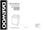
1
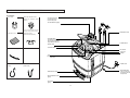
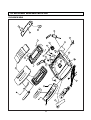
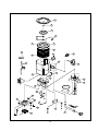
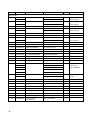
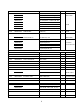
Service Manual
Full-Auto Electric Washing Machine
DWF-7560/7590 series
DWF-8060/8090 series
DAEWOO ELECTRONICS CO., LTD.
TABLE OF CONTENTS
1. SPECIFICATIONS..................................................................................................................................................................... 2
2. FEATURE AND TECHNICAL EXPLANATION ...................................................................................................................... 3
CONTROL SYSTEM FOR AUTO COURSE ............................................................................................................................. 3
CONTROL SYSTEM FOR WOOL WASH ................................................................................................................................ 3
CONTROL SYSTEM FOR WOOL SPIN ....................................................................................................................................4
WATER FLOW TO ADJUST THE UNBALANCED LOAD.........................................................................................................4
FUNCTION FOR SOAK WASH..................................................................................................................................................4
AUTOMATIC WATER SUPPLY SYSTEM ON BLANKET WASH ............................................................................................5
WATER FLOW ON STRONG WASH.........................................................................................................................................5
PULSATOR SYSTEM .................................................................................................................................................................5
AUTOMATIC DRAINING TIME ADJUSTMENT ........................................................................................................................6
SOFTENER DISPENSER............................................................................................................................................................7
AUTOMATIC UNBALANCE ADJUSTMENT .............................................................................................................................8
CIRCULATING-WATER COURSE AND LINT FILTER..............................................................................................................8
AUTOMATIC POWER OFF ........................................................................................................................................................9
RESIDUAL TIME DISPLAY.........................................................................................................................................................9
DRAIN MOTOR ...........................................................................................................................................................................9
WATER LEVEL SWITCH.............................................................................................................................................................9
GEAR MECHANISM ASS'Y .....................................................................................................................................................10
SAFETY DEVICE FOR MOTOR ...............................................................................................................................................10
PRINCIPLE OF BUBBLE GENERATOR..................................................................................................................................10
FUNCTIONAL PRINCIPLE OF BUBBLE WASHING MACHINE............................................................................................11
3. STRUCTURE OF WASHING MACHINE.............................................................................................................................. 12
STRUCTURE OF WASHING MACHINE .................................................................................................................................12
FUNCTION OF CONTROL PANEL..........................................................................................................................................13
4. INSTALLATION INSTRUCTIONS......................................................................................................................................... 14
HOW TO INSTALL OF THE WASHING MACHINE ................................................................................................................14
HOW TO CONNECT THE INLET HOSE..................................................................................................................................16
HOW TO REROUTE THE DRAIN HOSE .................................................................................................................................17
HOW TO INSTALL THE DRAIN HOSE....................................................................................................................................18
HOW TO CLEAN THE DRAIN FILTER.....................................................................................................................................19
5. OPERATING INSTRUCTIONS.............................................................................................................................................. 20
PROCEDURE OF FULL-AUTOMATIC WASHING .................................................................................................................20
PARTIAL SELECTIONS AMONG WASH, RINSE AND SPIN ................................................................................................22
6. PROGRESS CHART............................................................................................................................................................... 24
7. HOW TO CHECK THE P.C.B. ASS'Y................................................................................................................................... 28
8. WIRING DIAGRAM................................................................................................................................................................. 29
9. DIRECTIONS FOR DISASSEMBLY AND ADJUSTMENT................................................................................................. 32
GEAR MECHANISM ASS'Y REPLACEMENT ........................................................................................................................32
DRAIN MOTOR VALVE REPLACEMENT................................................................................................................................33
BRAKE ADJUSTMENT.............................................................................................................................................................33
10. EXPLODED VIEW AND PART LIST ......................................................................................................................................34
EXPLODE VIEW ........................................................................................................................................................................34
PARTS LIST...............................................................................................................................................................................37
11. TROUBLE SHOOTING GUIDE .............................................................................................................................................. 41
CONCERNING WATER SUPPLY............................................................................................................................................41
CONCERNING WASHING .......................................................................................................................................................42
CONCERNING DRAINING.......................................................................................................................................................43
CONCERNING SPINNING.......................................................................................................................................................44
CONCERNING OPERATIONS.................................................................................................................................................45
CONCERNING ERROR MESSAGE ........................................................................................................................................46
1
1. SPECIFICATIONS
NO
ITEM
SPECIFICATIONS
1
POWER SOURCE
2
POWER
DWF-7560/90
370W (50Hz), 460W (60Hz)
CONSUMPTION
DWF-8060/90
400W (50Hz), 480W (60Hz)
MACHINE
DWF-7560/90
NON PUMP: NET; 48kg, GROSS; 52kg PUMP: NET; 49kg, GROSS; 53kg
WEIGHT
DWF-8060/90
NON PUMP: NET; 49kg, GROSS; 53kg PUMP: NET; 50kg, GROSS; 54kg
3
Available in All Local AC Voltage and Frequency
4
DIMENSION (WXHXD)
650X1005X650 mm
5
WASHING COURSE
6
WATER CONSUMPTION
7
WATER LEVEL
DWF-7570/90
HIGH (80 `), MIDDLE (68 `), LOW (55 `), SMALL (42 `), E.SMALL (32 `)
SELECTOR
DWF-8060/90
HIGH (82 `), MIDDLE (70 `), LOW (57`), SMALL (43 `), E.SMALL (32 `)
Full Automatic 6 Courses:
DRY; FUZZY, DRY, SILK, SPEED, STRONG, BLANKET
NON DRY; FUZZY, WOOL, SPEED, STRONG, BLANKET, NIGHT
and MEMORY Course
259 ` (7.5kg), 265 ` (8.0kg)
0.3~8kg/cm2 (2.9~78.4N/cm2)
8
OPERATING WATER PRESSURE
9
REVOLUTION PER MINUTE
10
PULSATOR
11
WATER LEVEL CONTROL
12
OUTER CABINET
13
ANTI-NOISE PLATE
14
GEAR MECHANISM ASSY
15
LINT FILTER
O
16
SOFTENER DISPENSOR
O
17
AUTO. LOAD SENSING
O
18
AUTO. POWER OFF
O
19
FUNCTION FOR SOAK WASH
O
20
ALARM SIGNAL
O
21
RESIDUAL TIME DISPLAY
O
22
AUTO. RE-FEED WATER
O
23
NEW WATER FLOW
24
TRANSPARENT WINDOW
O
25
FUNCTION FOR BUBBLE
O
26
MAXIMUM
MASS of
TEXTILE
SPIN: 680rpm, WASH: 130rpm (50Hz)
SPIN: 780rpm, WASH: 150rpm (60 Hz)
WOOL WASH: 70rpm
6 WINGS (ø 376mm)
ELECTRONICAL SENSOR
PLASTIC
O
HELICAL GEAR FOR LOW NOISE
WATER FLOW FOR ADJUSTING THE UNBALANCED LOAD
DWF-7560/90
7.5kg
DWF-8060/90
8.0kg
2
2. FEATURE AND TECHNICAL EXPLANATION
CONTROL SYSTEM FOR AUTO COURSE
FUNCTION PRINCIPLE OF SENSING
1) Sensing the wave width of two ports of capacitor.
2) Choosing the 'A~D' course according to the wave width.
3) Setting up the most suitable time to wash, rinse and spin by the judgement.
SENSING TIME
Sense the wave width for 28 seconds from start of washing.
OPERATING PROCESS ACCORDING TO THE WASHING CAPACITY
COURSE
WASHING
CAPACITY
WATER
LEVEL
WASH
TIME
TIMES OF
RINSE
SPIN
TIME
A
0~2.0 Kg
E.Low
6 min
2
3 min
B
1.0~3.0 Kg
Low
9 min
2
4 min
C
2.0~4.0 Kg
MIDDLE
12 min
2
5 min
D
Above 3.0 Kg
High
15 min
2
5 min
CONTROL SYSTEM FOR WOOL WASH
R.P.M of pulsator become half of normal wash by signal of P.C.B. Ass'y.
INPUT WAVE FORM OF MOTOR ON WOOL WASH
DRY/WOOL WASH
3sec ON
5sec OFF
3sec ON
(C.W)
4sec ON
SILK WASH
[Only DRY series]
5sec OFF
(C.W)
5sec OFF
4sec ON
(C.W)
5sec OFF
(C.W)
PROCESS OF WOOL WASH
When the DRY WOOL COURSE is selected, process shall be set up as below table automatically.
(LOAD TO BE
WASHED)
WATER
LEVEL
WASH
TIME
TIMES OF
RINSE
SPIN
TIME
WASH
TEMP.
(Below 2 Kg)
MIDDLE
6 min
2
30 sec
COLD
NOTE: You can't change the water temperature because the P.C.B. ASS'Y set up the 'COLD TEMP' automatically at the
same time you select the 'WOOL COURSE'.
3
CONTROL SYSTEM FOR WOOL SPIN
It is a function to prevent the deformation of WOOL.
PROGRESS CHART ON WOOL SPIN
NORMAL
WOOL
R.P.M.
ON-OFF
TIME
OF
MOTOR
(sec)
4
3
4
3
3
2
4
3
4
3
3
2
2
7
4
7
4
WOOL
NORMAL
BALANCE SPIN
NORMAL SPIN
WATER FLOW TO ADJUST THE UNBALANCED LOAD
It is a function to prevent eccentricity of the clothes after wash by rotating pulsator C.W and C.C.W for 20 seconds.
EFFECT
Reduce vibration and noise effectively while spinning.
WATER FLOW
I
WASH
DRAIN
SPIN
FILL
0.3
0.5
RINSE 1 I
DRAIN
SPIN
FILL
RINSE 2 I
C.W
SIGNAL
C.C.W
TIME (sec)
0.3
0.5
0.3
0.5
.........
20 sec (About 13 Cycles)
FUNCTION FOR SOAK WASH
DISPLAY THE REMAINING TIME
When the SOAK WASH is selected, the total wash time will increase by 40 minutes.
PROGRESS
SOAK PROCESS
FILL
•
WASH
2min I
STOP
WASH
12min 1min I
STOP
MAIN PROCESS
WASH
STOP
12min 1min I
12min
40 Minutes
NOTE: "I" Mark shows the water flow to adjust the unbalanced laod.
4
DRAIN
...
AUTOMATIC WATER SUPPLY SYSTEM ON BLANKET WASH
The water level would be lowered because the blanket absorbs water at the beginning of washing.
Therefore, after 30 seconds, the operation is interrupted to check the water level, and then the water is supplied again until it
is reached at the selected level.
WATER FLOW ON STRONG WASH
It washes cleanly the heavily stained clothes such as working-clothes, climbing-clothes and blue-jean by using this strong
water currents as shown below.
WATER FLOW
SIGNAL
OF
MOTOR
TIME (sec)
C.C.W
C.W
0.8 0.5 0.8 0.5 0.8 0.5 0.8 0.5 0.8 0.5 0.8 0.5 0.8 0.5 0.8 0.5 3.2 0.8 3.2 0.8
1 CYCLE
PULSATOR SYSTEM
When the new shaped pulsator is rotated C.W or C.C.W at a high speed, it makes the 'heart-shaped' water currents as
shown below.
C
WATER FLOW
A
Rotate
B
C
B
A
A
5
Water is pushed out by rotation of
the pulsator.
Water is pulled down by rotation
of the pulsator.
Water flow is generated by
rotation of the pulsator.
AUTOMATIC DRAINING TIME ADJUSTMENT
This system set a drain time automatically depending on condition of draining.
Draining
condition
Good draining
The washer begins spin process after drainage.
Bad draining
Draining time is prolonged.
No draining
Program is stopped and gives the alarm.
FUNCTIONAL PRINCIPLE
1. The micom can remember the time from the beginning of drain to reset point when the pressure switch reaches to "OFF"
point.
Drain Time
Movement of the program
Less than
5 minutes
Continue draining.
More than
5 minutes
Program are stopped and give an alarm with twinkle the "
" on display lamp.
2. In case of continuous draining, residual drain time is determined by micom.
Total drain time = D + 60
(T sec)
Time of remaining drain process.
Count time of P.C.B. ASS'Y.
(mm)
TRIP POINTS
* 400
340
*
*
T5
T4
T3
D1
T2
T1
60
*
D5
D4
220
D3
170
D2
*
*
E. SMALL
SMALL
*
*
LOW
MIDDLE
RESET POINTS
60
0
HIGH
T1=D1+60 (sec) T2=D2+60 (sec) T3=D3+60 (sec)
T4=D4+60 (sec) T5=D5+60 (sec)
6
WATER LEVEL
DRAINING TIME
280
*
SOFTENER DISPENSER
This is the device to dispense the softener automatically by centrifugal force.
This is installed inside the auto-balancer.
FUNCTIONAL PRINCIPLE
1. Softener stays in room (A) when pour the softener to softener inlet.
2. Softener move (A) to (B) by centrifugal force during intermediate spin process.
3. Softener flow (B) to (C) during rinse process next of intermediate spin.
4. Softener move (C) to (D) by centrifugal force during second intermediate spin.
And after finish spin process, softener drop between tub and outer tub ass'y from softener outlet.
FLOW OF THE SOFTENER
Wash
Normal
intermediate
Spin
Centrifugal force
Hold
intermediate
Spin
Rinse
Flow by
weight
Centrifugal force
Flow by
weight
Spin
Course
(A)
(B)
(C)
(D)
FLOW OF THE SOFTENER INSIDE OF THE BALANCE
Room inside
the balancer
A
B
C
D
Flow by
Centrifugal
force
NOTE: Softener moves into next room when r.p.m of the tub is more than 100 r.p.m.
HOW TO CHECK MOVEMENT
Pour a reasonable amount of "MILK" into softener dispenser
and operate the washer with no load.
In final rinse cycle, make sure than the milk is added into the
tub through softener outlet.
Balancer
Softener outlet
B
A
Softener inlet
7
D
C
AUTOMATIC UNBALANCE ADJUSTMENT
This system is to prevent abnormal vibration during intermittent spin and spin process.
FUNCTIONAL PRINCIPLE
1. When the lid is closed, the safety switch contact is
"ON" position.
2. In case that wash loads get uneven during spin, the
outer tub hits the safety switch due to the serious
vibration, and the spin process is interrupted.
3. In case that P.C.B. ASS'Y gets "OFF" signal from the
safety switch, spin process are stopped and rinse
process is started automatically by P.C.B. ASS'Y.
4. If the safety switch is operated due to the unbalance
of the tub, the program is stopped and the alarm is
given.
Contact of safety switch
Lid closing
Lid opening
Contact lever A
Position of unbalanced load(OFF)
Normal(ON)
NOTE:
The alarm finish when you close the lid after opening it.
Check the unbalance of the wash load and the
installation condition.
CIRCULATING-WATER COURSE AND LINT FILTER
CIRCULATING-WATER
The washing and rinsing effects have been improved by adopting
the water system in which water in the tub is circulated in a
designed pattern.
When the pulsator rotates during the washing or rinsing process,
the water below the pulsator vanes creates a water currents as
shown in figure.
The water is then discharged from the upper part of the tub
through the water channel.
About 40L/min. water is circulated at the 'high' water level,
standard wash load and standard water currents.
Tub
Filter
Outer tub
Water
channel
Pulsator
LINT FILTER
Much lint may be obtained according to the kind of clothes
to be washed and some of the lint may also sticks to the clothes.
To minimize this possibility, a lint filter is provided on the upper
part of the tub to filter the wash water as it is discharged from the
water channel. It is good to use the lint filter during washing.
Bleach inlet
HOW TO CLEAN THE LINT FILTER
1. Pull the filter frame upward.
2. Turn the lint filter inside out, and wash the lint off with water.
3. Return the filter as it was, and fix the filter frame to the slot.
8
Filter
Pulsator
AUTOMATIC POWER OFF
P.C.B. ASS'Y sends a signal to the solenoid in the power switch 10 minutes later after complete washing.
Then the solenoid pull the locking lever which had lock the push button. Therefore the power is turned off automatically.
RESIDUAL TIME DISPLAY
When the START/HOLD button is pressed, the residual time (min.) is displayed on the time indicator, and it will be counted
down according to the process.
When operation is finished, the TIME INDICATOR will light up ‚ .
DRAIN MOTOR
STRUCTURE
Pull
Loosen
Pulley
Lever
Inductive ring
Magnet
Coil of motor
Magnet of motor
FUNCTIONAL PRINCIPLE
1. When the DRAIN MOTOR connected to the power source (AC 220V), the DRAIN MOTOR rotates with 900 r.p.m and
revolves the pulley by gear assembly for reducing.
2. When the pulley is rotated, the pulley winds the wire to open the drain valve.
3. Therefore, rotation of pulley is changed to the linear moving of wire.
4. The wire pulls the brake lever of Gear Mechanism Ass'y within 5 seconds.
5. After the wire pulled, gear assembly is separated from motor and condition of pulling is held by operation of the lever.
6. When the power is turned off, the drain valve is closed because the wire returns to original position.
WATER LEVEL SWITCH
Water pressure of air room which is at the side of outer-tub is transmitted to the air room in the water level switch through
air-tube. Diaphragm moves up and down by the transmitted pressure to move the core.
Movement of core transforms the inductance of coil by Henly's Law.
The generative frequency (Hertz) is obtained by this transformation of the coil inductance in the LC generative circuit.
Spring
Spring
Coil
Coil
Case
Core
Core
Diaphragm
Case
Diaphragm
(rubber)
Air-pressure
9
GEAR MECHANISM ASS'Y
The proper water currents is made by the rotation of pulsator at a low speed (about 145 r.p.m) to prevent the damage to
the small sized clothes.
Pusator Shaft
Spinner Shaft
Roller Clutch
Bearing
Sun gear
Planetary
Gear
Planetary gear
Internal gear
Brake Lever
Clutch Boss
Spinner Pulley
Pulsator
Motor
1700 r.p.m
(60Hz)
1400 r.p.m
(50Hz)
Planetary
1 revolution
Motor
Pulsator
Planetary 140 r.p.m
gear
(60Hz)
150 r.p.m
(50Hz)
60 r.p.m
(60Hz)
70 r.p.m
(50Hz)
Dry/Silk
V.BELT
5 revolutions
Spinner
pulley
Spinner Pulley
TUB
650 r.p.m
(60Hz)
740 r.p.m
(50Hz)
650 r.p.m
(60Hz)
740 r.p.m
(50Hz)
Directly
V-Belt
SAFETY DEVICE FOR MOTOR
In case of occurring disorder of motor caused by extreme-high
voltage, over-heating, overload, safety devices (Thermal
Protector) of motor can be operated and cut off the power
sources automatically.
At this case, motor does not run.
However, motor can be operated normally again about 1 hour
later.
Thermalprotector
Violet
White/Red
Blue
PRINCIPLE OF BUBBLE GENERATOR
(Motor)
STRUCTURE
Bobbin & coil
Armature
Magnet
Bellows
Trans core
Air
Air
Air out hole
Air in hole
Protector A
Protector B
10
PRINCIPLE OF INTAKE & OUTLET OF THE AIR
INTAKE : ARMATURE moves to the upper side, and BELLOWS inhales the air. At same time, PROTECTOR B is open and A
is close.
OUTLET: ARMATURE moves to the down side, and BELLOWS exhaust the air. At same time, PROTECTOR B is close and
A is open.
FUNCTIONAL PRINCIPLE OF TRANS & MAGNET
• A.C electric power's phase changes to 60 cycle/sec.
• Trans core's magnetic pole is changed by changing of A.C electric power's phase.
• The core repeat push and pull (3600 times/min) the armature magnet.
A.C
A.C
N
NS
S
S
Pan spring
NS
Trans core
N
Magnet
FUNCTIONAL PRINCIPLE OF BUBBLE WASHING MACHINE
ACROSS SECTION
Air bubble
Tub
Outer tub
Pulsator
Nozzle
FUNCTIONAL PRINCIPLE
Bubble generator supplies the air from the bottom of outer tub to the inner space of pulsator, the air break up by pulsator's
agitating spin. Air-bubble was created by the centrifugal force, and rise up.
11
3. STRUCTURE OF THE WASHING MACHINE
STRUCTURE OF WASHING MACHINE
ACCESSORIES
Hose Clamp
Water Tap Adapter (COLD)
Water Tap Adapter (HOT)
[option]
• COLD WATER INLET
After using the machine,
close the water faucet
and turn off the power.
• HOT WATER INLET [Option]
In case of screw-shaped inlet hoses
water tap adapters will be provided.
Under Base Cover
• DETERGENT CASE
Inlet Hose (COLD)
Inlet Hose (HOT) [Option]
• SOFTENER INLET
Pour softener into the softener
inlet and it will be added the
tub just before the final rinse.
• POWER SWITCH
• BLEACH INLET
• CONTROL PANEL
Bottom Board Cover [Option]
• LINT FILTER
• PULSATOR
• HANDLE
• TUB
(SUS: DWF-8060
DWF-8090)
Drain Hose
[PUMP]
• POWER CORD
[NON-PUMP]
• UNDER BASE COVER
UP
• BOTTOM BOARD COVER
[Option]
• LEG COVER
[Option]
12
• GROUNDING WIRE
In case of 3-pin power
cord grounding wire will
not be provided.
FUNCTION OF CONTROL PANEL (DRY)
Control Panel
• It has micom sensor.
• As the button is pressed, course is
selected by your desired.
Use of Switch
• Power Switch
–Press to turn the
power On or Off
OFF
• After turning off
the power, wait
for over 3
seconds and then
turn it On again.
ON
Button for Program
Cancel
Wash Time
Pre-engagement
• It can be used to cancel
the full-automatic course.
• When the button is
pressed time, display will
be light down.
If you want to wash, rinse
or spin, you can press
one of the other buttons.
• It can be used to preengage time for wash
Time Display
Exclusive Spin
Button
•The lamps easily
indicate the option
selection of wash
program and
process by letters.
•It can be used to
spin exclusively.
AUTO OFF
DAEWOO AUTOMATIC
WASHER
AERO FUZZY & AIR POWER
TIME
COURSE
SOAK WASH
RINS SPIN
WASH RINS
SPIN
FUZ.
DRY
SILK
RES
HOUR
HOUR
RES.
MIN.
TIME
MEM.
MIN.
REM.
SPEE
STRO
BLAN
TEMP. LEVEL
HOT
WARM
COLD
Start/Hold Button
Memory Button
•Operation and
temporary stop are
repeated as it is
pressed.
•It will be repeated
(operation),
(temperary stop)
according to the one
time pressing or two
times pressing.
•It can be used by
remembering by
your desire.
START/HOLD
H.
M.
L..
S.
E.S.
Dry cleaning
SPIN
ONLY
CANCEL
WASH
RINSE
SPIN
COURSE
MEM
ORY
WASH TEMP. WATER LEVEL
Water Level Selector
Wash Time Selector
Rinse Time Selector
Speed Time Selector
Course Selection
•It can be used to adjust
washing time.
•This button selects the
number of time you want
to rinse.
•It can be use to adjust
spin time.
•It can be used to select
the full-automatic course.
•As the button is pressed,
it will be selected
following order;
DRY: Dry ¤ASilk ¤ASpeed ¤A
Strong ¤ABlanket ¤AFuzzy
13
Water Temperature
Selection [Option]
•It can be used to select the water
temperature according to the
clothes being washed.
•If you select 'Dry/Silk Washing',
selection for water temperature is
selected 'Cold' by automatically in
order to prevent the laundry from
damage.
•It can be used to adjust
amount of water according to
the size of the load to be
washed.
•If you select 'Dry/Silk
Washing', Selection for water
level is selected 'MID;
automatically in order to
prevent the laundry from
damage.
FUNCTION OF CONTROL PANEL (Non-Dry)
Control Panel
• It has micom sensor.
• As the button is pressed, course is
selected by your desired.
Use of Switch
• Power Switch
–Press to turn the
power On or Off
OFF
• After turning off
the power, wait
for over 3
seconds and then
turn it On again.
ON
Button for Program
Cancel
Wash Time
Pre-engagement
• It can be used to cancel
the full-automatic course.
• When the button is
pressed time, display will
be light down.
If you want to wash, rinse
or spin, you can press
one of the other buttons.
• It can be used to preengage time for wash
Time Display
Exclusive Spin
Button
•The lamps easily
indicate the option
selection of wash
program and
process by letters.
•It can be used to
spin exclusively.
AUTO OFF
DAEWOO AUTOMATIC
WASHER
AERO FUZZY & AIR POWER
TIME
COURSE
SOAK WASH
RINS SPIN
WASH RINS
SPIN
FUZ.
SPEE
WOOL
RES
HOUR
HOUR
RES.
MIN.
TIME
MEM.
MIN.
REM.
STRO
NIGHT
BLAN
TEMP. LEVEL
HOT
WARM
COLD
Start/Hold Button
Memory Button
•Operation and
temporary stop are
repeated as it is
pressed.
•It will be repeated
(operation),
(temperary stop)
according to the one
time pressing or two
times pressing.
•It can be used by
remembering by
your desire.
START/HOLD
H.
M.
L..
S.
E.S.
Dry cleaning
SPIN
ONLY
CANCEL
WASH
RINSE
SPIN
COURSE
MEM
ORY
WASH TEMP. WATER LEVEL
Water Level Selector
Wash Time Selector
Rinse Time Selector
Speed Time Selector
Course Selection
•It can be used to adjust
washing time.
•This button selects the
number of time you want
to rinse.
•It can be use to adjust
spin time.
•It can be used to select
the full-automatic course.
•As the button is pressed,
it will be selected
following order;
NON-DRY: Speed ¤A W o o l¤A
Strong ¤A Nigh t¤ABlanket
¤A Fuzzy
13-1
Water Temperature
Selection [Option]
•It can be used to select the water
temperature according to the
clothes being washed.
•If you select 'Dry/Silk Washing',
selection for water temperature is
selected 'Cold' by automatically in
order to prevent the laundry from
damage.
•It can be used to adjust
amount of water according to
the size of the load to be
washed.
•If you select 'Dry/Silk
Washing', Selection for water
level is selected 'MID;
automatically in order to
prevent the laundry from
damage.
4. INSTALLATION INSTRUCTIONS
HOW TO INSTALL OF THE WASHING MACHINE
SELECTION OF THE INSTALLING PLACE
• Choose a place on a horizontal
solid floor. When the washer is
installed on unstable floor, it
makes noise and vibration.
• Don't choose a floor where direct
rays of the sun.
Because the washing machine's
color becomes different.
• Avoid installing it in a place where
it can be exposed to rain that may
cause it rust and leak.
• Coal gas may cause corrosin.
• Don't install in the place where it is
anxious about being frozen in
winter.
* NOTE
The opening must not be
obstructed by carpeting when the
washing machine is installed on a
carpeted floor.
When the washer is installed on an unsuitable floor, it makes noise
and vibration and occures out of order.
IN CASE THAT THE WASHER IS INCLINED
¡
Insert the Height
Adjust Rubber
ƒUInsert the ‘height adjust rubber’ to
the inclinded direction. It can be
adjusted as far as 30mm.
™
£
Height Setting
ƒUControl the height by turning the
adjusting leg. After that turn the
outer cap to be locked.
• Don't turn the adjusting leg to be
separate.
Height
Adjust
Rubber
Lock
Loose
14
Check the Horizon
ƒUCheck the position at the front
center of the washer.
After the selection of the installing place is finished, you close the
under base cover.
INSTALLATION OF THE UNDER BASE COVER
¡
Open the box packing, and it is on the
washer.
™
£
There is a inserting
place under of the
front side on the
washer.
Let the under base
cover that can be
shown the "UP" sign.
¢
Put it to enter bottom
board cover rack
surely. (DWF-7590TE)
UP
GROUNDING METHOD
•Attach the grounding wire to a
copper plate or grounding rod and
bury it in the ground.
•Connect the grounding wire to a
metal water faucet.
•In the case of 3-core cord there is
no need for a grounding wire.
20Cm
* It is not use connecting the wire to the
plastic pipe.
DO NOT CONNECT THE GROUNDING WIRE TO SUCH A THING
•Do not connect the gas tube because it is attended
with danger of a explosion.
•Do not connect to the telephone wire or a lightning
rod because it is attended with danger of the strike
fire.
15
HOW TO CONNECT THE INLET HOSE
IN INSTALLING THE INLET HOSE
Be careful not to mistake in supplying hot and cold
water.
In using only one water tap, connect the inlet hose to the
cold water inlet.
Hot
Water
¡
Pull down the collar
of the inlet hose to
separate it from the
water tap adapter.
Cold
Water
™
Water Tap
Adapter
Tape
Rubber
packing
Collar
Loosen the four
screw at the water
tap adapter, but
don't loosen the
screws until they are
separated from the
water tap adapter.
Connector A
Tap
Adapter
Connector C
£
¢
Connect the water
tap adapter to the
water tap, and tighten
the four screws
evenly while pushing
up the adapter so that
the rubber packing
can stick to the water
tap tightly.
∞
Remove the tape,
and screw connector
B into connector A
tightly.
Connect the inlet
hose to the water tap
adapter by pulling
down the collar of
the hose end.
Connector B
§
Connect the connector C of the inlet
hose to the water inlet
of the washer by
turning it clock-wise
to be fixed tightly.
Connector A
@
Collar
Connector B
!
• Please check the rubber
packing inside the
connector C of the inlet.
Water Tap Adapter
• FOR SCREW-SHAPED TAP
¡
™
Connect the inlet
hose to the water tap
by screwing the
connector D tightly.
Connector D
Hose
Rubber
Packing
Connector C
16
Connect the connector C of the inlet hose to the
water inlet of the
washer by turning
it clockwise to be
fixed tightly.
HOW TO REROUTE THE DRAIN HOSE
¡
¢
Pull out the under base cover to
the arrow direction.
After detaching the drain hole
cover of the hoping direction,
insert the inside drain hose.
And then fasten the fixing
screw.
™
∞
After spreading blanket or unit
box, lay the washer as the
below figure. And detach the
ouside drain hose with widening
drain clip.
Insert the outside drain hose
together with the hose-fixing
clip.
£
§
Datach the inside drain hose
fixing screw with §]driver.
Insert the detached drain-hole.
HOSE TO USE IN WINTER
• To avoid the washing machine's being frozen.
– Remove the inside water of the washing machine
completely.
– Remove the inside water of the inlet-hose and drain-hose
completely.
• In case of being frozen.
– Dip the detached inlet-hose in the hot water (about 50°C)
* (Don't use above 50°C surely).
– Leave the tub alone for 10 minutes with pouring the hot
water. (about 50°C)
– Check the drain and inlet's operation after attching the
inlet hose.
17
HOW TO INSTALL THE DRAIN HOSE
NOTE IN USING THE DRAIN HOSE
Never forget to install drain hose before operating this washing machine.
There are a drain hose, a hose clamp, a hose fixture and a hose guide in the washing machine.
Connect the drain hose to the
drain outlet at the back side of the
washing machine, and fasten it
tightly with the clamp supplied.
™
Insert the hose fixture into hook
hole at the side of the body, and
fix the drain hose by inserting it
into the hose fixture.
£
Attach the hose guide, included in
the accessory kit, to guide the
drain hose over the tub or
standpipe.
Pull Hose
through
Drain Output
Hook Hole
Hose Fixture
Drain Hose
Drain hose
Hlex. Hose
Guide
apart
Hose Clamp
¢
Hook the drain hose to the edge
of the tub, paying attention that
there are no bends or
constractions along the drain
hose
Or, connect the drain hose to a
standpipe of a diameter greater than
that of the drain hose and at a height
of min. 70cm.
∞
55 mox
¡
Position the washing machine
next to the wall.
70Cm min
MUST be
ventilated
NOTES:
1. Keep the drain hose fixed tightly in the hose fixture, or let the highest point of the drain hose be more than 1m above the
floor.
2. Be sure that the height of the drain hose must be less than 1.5m above the floor.
If not so, the water in the washer could not drain.
3. The hoseguide MUST be fitted to the drain hose. The drain hose sould not extend more than 55mm from the end of the
hose guide. This is to prevent ‘SYPHONING’.
If necessary the drain hose can be trimmed to length.
18
HOW TO TO CLEAN DRAIN FILTER [Pump]
In this washer machine, the drain filter is equipped at the back side of it.
This drain should be cleaned frequently (every 5 times of use) for its smooth operation.
And this should be cleaned frequently (every 5 times of use) for its smooth operation.
Drain problem could be caused if the drain filter is not cleaned at proper time.
Please keep it clean.
In case you clean the drain filter, please follow the instructions as below.
Remove the
remained water
¡
ƒUPut down the remained water in
the hose. And put a container
under the filter to collect water.
™
Unscrew the cap
ƒUTurn the cap counter clockwise.
£
Release the filter
assembly
ƒUPull our the filter assembly off the
case of the main body.
SLIT
CASE
HOSE
CAP
FILTER
¢
CONTAINER
Remove the
remained water
ƒUClean the drain filter removing the
foreign stuffs.
FILTER
∞
Unscrew the cap
ƒUPut in the filter along the guiding
prominence of the case. Please
note the right position of the filter
adjusting the groove to the guide
rib.
∞
Release the filter
assembly
ƒUTurn the cap clockwise tightly.
CASE
FILTER
CAP
GUIDE
RIB
CAP
CAP
SLIT
NOTES: During the operation, the “OE” signal means drain error can be displayed on the control panel.
In this case, the main cause of that problem is the blocking of the drain filter.
If you clean the drain filter following above instructions, you could continue the normal operation of the washing
machine to reset the program, please turn the power off and on again.
19
5. OPERATING INSTRUCTION
PROCEDURE OF FULL-AUTOMATIC WASHING
¡
FullAutomatic
™
Select the Course
This selection is for general
washing.
£
Procedure of
Pressing the Button
FUZZY
START/HOLD
FUZZY
(SENSOR)
SPEED
SOAK WASH RINS
SPIN
HOUR MIN.
MIN.
TIME
This selection is effective for
washing light or less dirty wash.
Prepare
for
washing.
¤D
Pressing
the
power
switch.
¤D
Put the
wash in.
¤D
Select
the
detergent.
SPIN
HOUR MIN.
MIN.
TIME
This selection is effective for
blue-jean, climbing clothes,
ruck-sack, sports wear, etc...
SPIN
HOUR MIN.
MIN.
TIME
This selection is effective for
blacket, curtain, carpet, etc...
SPIN
This selection is effective for
high quality sweater, cardigan,
all-wool clothes and all-wool
garments.
HOUR MIN.
MIN.
* Appropriate volume of washes are
two or three suits of clothes.
SILK
SOAK WASH RINS
SPIN
HOUR MIN.
MIN.
TIME
HOUR MIN.
NONDRY
series
TIME
* Appropriate volume of washes are
five suits of silk blouses.
SPIN
MIN.
* Do not put in the wash marked with
‘dry-cleaning’.
* 2kg’s limitation for one-time-wash.
NIGHT
SOAK WASH RINS
SPIN
HOUR MIN.
MIN.
TIME
This selection is effective for
silk lingerle, stocking, silk
curtains, and other silk
garments.
This selection is effective for
high quality sweater, silk,
underwear, stocking, etc..
WOOL
SOAK WASH RINS
BLANKET
START/HOLD
COURSE
SOAK WASH RINS
TIME
START/HOLD
* 4kg's limitation for one-time-wash.
DRY
DRY
series
STRONG
COURSE
BALANKET
SOAK WASH RINS
START/HOLD
COURSE
STRONG
SOAK WASH RINS
SPEED
DRY
START/HOLD
COURSE
SILK
START/HOLD
COURSE
WOOL
START/HOLD
COURSE
This selection is for a nightwashing housewife who has no
opportunity at day time.
NIGHT
COURSE
20
START/HOLD
¢
Procedure of Washing (Washing machine does it automatically.)
Sensing load,
inlet and wash.
SPIN
SPIN
RINSE
Artificial brain computer controls full procedure proper to
wash load automatically.
Water inlet and
wash for 10 minutes.
SPIN
RINSE
SPIN
Total 27 minutes.
End of
washing
informed by
buzzer.
Water inlet and
wash for 14minutes.
SPIN
RINSE
SPIN
A strong course's water flow is
Water inlet and
wash for 12 minutes.
SPIN
RINSE
Water inlet and
wash for 6 minutes.
SPIN
RINSE
R
SPIN
A blanket course's water flow is
SPIN
SPIN
RINSE
L
R
R
R
L
R
L
R
L
SPIN
RINSE
R
L
L
L
R
L
SPIN
RINSE
The rotation velocity at a part of dotted line is decreasing for protection
of wool, etc. damage.
Water inlet and
wash for 4 minutes.
SPIN
RINSE
SPIN
SPIN
RINSE
The rotation velocity at a part of dotted line is decreasing for protection
of silk, from damage.
After Washing
• Close the water tap and separate it from the inlet-hose.
If not so, the jnlet valve is excessive by the water pressure.
• Take off plug.
21
After 10
minutes later
from the end
of the
washing, the
power switch
is turned off
automatically.
PARTIAL SELECTIONS AMONG WASH, RINSE AND SPIN
¡
Washing Procedure
by Your Desire
™
Pressing the button
ONLY
SPIN
ONLY SPIN
Cancel the set program with
pressing the "cancel" Button.
ONLY WASH
ONLY RINSE
WASH ¤A RINSE ¤A SPIN
WASH ¤A RINSE
WASH ¤A SPIN
CANCEL
* In case of canceling the
program while the washing
machine operates, press the
"Start/Hold" button first, and
then press “Cancel” Button.
RINSE ¤A SPIN
WASH
RINSE
SPIN
WASH
RINSE
SPIN
WASH
RINSE
SPIN
WASH
RINSE
SPIN
WASH
RINSE
SPIN
WASH
RINSE
SPIN
WASH
RINSE
SPIN
EXPLAIN FUNCTION OF BUTTON
WASH
WASH
‹
WASH
⁄›
After input water, wash in
3 minutes.
MIN.
MIN.
WASH
fl
WASH
¤‚
After input water, wash in
6 minutes.
MIN.
WASH
‹‚
After input water, wash in
8 minutes.
MIN.
WASH
››
After input water, wash in
10 minutes.
MIN.
MIN.
WASH
⁄¤
After input water, wash in
30 minutes.
MIN.
WASH
⁄‚
After input water, wash in
20 minutes.
MIN.
WASH
°
After input water, wash in
14 minutes.
After input water, wash in
12 minutes.
MIN.
22
Soak wash; soak in 30
minutes before the
washing. And the
washing is progress.
£
Start/Hold Button
Press the "Start/Hold" button.
¢
∞
Washing Procedure
The course is processed by your
desire.
End of Washing
End of washing informed by buzzer.
START/HOLD
* After 10 minutes later from the end
of the washing, the power switch is
turned off automatically.
* If one more pressed, the washing
machine will be stopped. For
keeping operation continuously to
the set program, press another
time.
RINSE
SPIN
RINS
⁄
SPIN
⁄
1 time
TIME
RINS
¤
SPIN
‹
2 times
TIME
SPIN
›
3 times
TIME
SPIN
fi
4 times
TIME
Spin in 5 minutes.
MIN.
RINS
fi
Spin in 4 minutes.
MIN.
RINS
›
Spin in 3 minutes.
MIN.
RINS
‹
Spin in 1 minute.
MIN.
SPIN
·
5 times
TIME
MIN.
23
Spin in 9 minutes.
2
min
1
min
A+STOP
SPIN
BUZZER
DRAIN
RINSE
(BC:15")
BALANCE
SPIN
SPIN
WATER
SUPPLY
SPIN
A+STOP
DRAIN
RINSE
(BC:15")
BALANCE
SPIN
RINSE (2)
WATER
SUPPLY
SPIN
A+STOP
DRAIN
BALANCE
SPIN
SOAK
WATER
SUPPLY
SENSING
WASH
(BC:15")
RINSE (1)
TOTAL
OPERATING
TIME
2
min
FUZZY
15 4 30 30 20 14 12 10 8
6
4 2 30 2 30 1 40 20 90 40 4 3 30 2 2 30 2 30 1 40 20 90 40 4 3 30 2 2 30 5 4
3 30 90 10
sec min min min min min min min min min min min sec min sec min sec sec sec sec min min sec min min sec min sec min sec min sec sec min min sec min min sec min min min sec sec sec
MIN-SEC
H
W/S
53-10
M
W/S
51-10
24
L
W/S
45-10
S
W/S
42-10
SPEED
H
W/S
33-20
M
W/S
33-20
L
W/S
33-20
S
W/S
33-20
BLANKET
H
W/S
W/S
53-10
M
W/S
W/S
53-10
L
W/S
W/S
53-10
S
W/S
W/S
53-10
1. B.C.: 15": THIS IS A FUNCTION TO FLAT MOVING PULSATOR, LEFT, RIGHT FOR 15 SECONDS TO PREVENT
ECCENTRICITY OF THE LAUNDRY AFTER WASHING. (EXCEPT DRY, SILK)
2. THE 'A' INDICATES THE INERTIA RUNNING AT MOTOR STOP CONDITIONS.
3. THE 'W/S' INDICATES THE RINSE PROCESS ON WATER SUPPLY CONTINUOUSLY.
4. PROCESS OF E.SMALL WATER LEVEL IS THE SAME AS PROCESS OF SMALL WATER LEVEL
5. THE FILL TIME AND DRAIN TIME WILL VARY ACCORDING TO THE WATER PRESSURE, HOSE LENGTH, AND AFTER CONDITIONS.
6. DURING THE BALANCE SPIN. THE TUB WILL ROTATE AND STOP SEVERAL TIMES INTERMITTENLY.
7. PROCESS OF RINSE 2 TIME IS THE SAME AS RINSE PROCESS ON 'SENSOR COURSE'.
6. PROGRESS CHRT
WASH
1
MIN
2
MIN
1
MIN
A+STOP
SPIN
BUZZER
DRAIN
RINSE
(BC:15")
BALANCE
SPIN
SPIN
WATER
SUPPLY
SPIN
A+STOP
DRAIN
RINSE
(BC:15")
BALANCE
SPIN
RINSE (2)
WATER
SUPPLY
SPIN
A+STOP
DRAIN
WASH
(BC:15")
RINSE (1)
BALANCE
SPIN
SOAK
WATER
SUPPLY
SENSING
WASH
2
MIN
WOOL
25
SILK DRY
STRONG
15 4 30 30 20 14 12 10 8
6
4 2 30 2 30 1 40 20 90 40 4 3 30 2 2 30 2 30 1 40 20 90 40 4 3 30 2 2 30 5 4
3 30 90 10
SEC MIN MIN MIN MIN MIN MIN MIN MIN MIN MIN MIN SEC MIN SEC MIN SEC SEC SEC SEC MIN MIN SEC MIN MIN SEC MIN SEC MIN SEC MIN SEC SEC MIN MIN SEC MIN MIN SEC MIN MIN MIN SEC SEC SEC
NIGHT
TOTAL
OPERATING
TIME
MIN-SEC
H
W/S
W/S
51-10
M
W/S
W/S
51-10
L
W/S
W/S
51-10
S
W/S
W/S
51-10
H
33-00
M
31-00
H
36-30
M
36-30
L
36-30
S
86-10
H
86-10
M
86-10
L
86-10
S
86-10
* In case of the pump model, it doesn,t perform water input rinse (W/S).
NIGHT COURSE HAVE 3 TIMES RINSE PROCESS.
SOAK
1
2
min
min
15 4 30 30 20 14 12 10 8 2 30 2 30 1 40 90 4 3 30 2 2 30 2
sec min min min min min min min min min sec min sec min sec sec min min sec min min sec min
WASH ONLY
26
SPIN ONLY
A+STOP
SPIN
BUZZER
DRAIN
RINSE
(BC:15")
BALANCE
SPIN
SPIN
WATER
SUPPLY
SPIN
A+STOP
DRAIN
RINSE
(BC:15")
BALANCE
SPIN
SPIN
RINSE (2)
WATER
SUPPLY
DRAIN
BALANCE
SPIN
SOAK
WATER
SUPPLY
SENSING
WASH
(BC:15")
A+STOP
RINSE (1)
WASH
1
2
min
min
30 1 40 90 4 3 30 2 2 30 5 4 3 30 90 10
sec min sec sec min min sec min min sec min min min sec sec sec
TOTAL
OPERATING
TIME
min-sec
H
Process of selected course.
34• +
H
Process of selected course.
34• +
M
Process of selected course.
34• +
L
Process of selected course.
34• +
H
18•10
M
16•10
L
14•10
S
12•10
9
13•10
5
9•10
4
8•10
3
7•10
1
4•10
RINSE (2 TIME)
RINSE (3 TIME)
27
RINSE (1 TIME)
1
2
min
min
15 4 30 30 20 14 12 10 8 2 30 2 30 1 40 90 4 3 30 2 2 30 2
sec min min min min min min min min min sec min sec min sec sec min min sec min min sec min
BUZZER
SPIN
A+STOP
DRAIN
RINSE
(BC:15")
BALANCE
SPIN
SPIN
WATER
SUPPLY
SPIN
A+STOP
DRAIN
RINSE
(BC:15")
BALANCE
SPIN
SPIN
RINSE (2)
WATER
SUPPLY
DRAIN
BALANCE
SPIN
SOAK
WATER
SUPPLY
SENSING
WASH
(BC:15")
A+STOP
RINSE (1)
WASH
1
2
min
min
30 1 40 90 4 3 30 2 2 30 5 4 3 30 90 10
sec min sec sec min min sec min min sec min min min sec sec sec
TOTAL
OPERATING
TIME
min-sec
H
13•10
M
13•10
L
11•40
S
11•40
H
26•10
M
26•10
L
23•10
S
23•10
H
–
M
–
L
–
S
–
7. HOW TO CHECK THE P.C.B. ASS'Y
COURSE 1
Keep pushing three button (WASH, RINSE, SPIN SELECTOR) together and turn on the power switch.
DISPLAY
FUNCTION
¡
State of first lighting.
™
Temperature which sensing thermistor.
LO: Thermistor open.
HI: Thermistor short.
TIME
£
COURSE
SOAK WASH
RINS SPIN
WASH RINS
SPIN
FUZ.
DRY
SILK
HOUR
RES.
MIN.
TIME
MEM.
MIN.
REM.
SPEE
STRO
TEMP. LEVEL
HOT
WARM
COLD
BLAN
All LED light 8 times and go back to first
stage.
H.
M.
L..
S.
E.S.
COURSE 2
processing COURSE 1, push the spin selector once or three times according to desire check mode.
Time to push
the spin button
DISPLAY
FUNCTION
Pulsator rotate without water in the
tub and bubble pump on.
FUZ.
1st time
Drain ¤ASpin ¤ACold water ¤AHot water ¤A
Pulsator rotate (right) ¤ABubble ¤A
Pulsator rotate (left) ¤AAuto power off.
FUZ.
2nd time
FUZ.
All LED light 8 times and go back to first
stage.
3rd time
COURSE 3
How to upgrade of water level.
Processing "COURSE 2", push button below diagram.
DISPLAY
FUNCTION
Standard stage.
Upgrade of water level.
HOUR
SOAK WASH
RINS SPIN
HOUR
TIME
WASH RINS
SPIN
FUZ.
Fix the changing water level.
MIN.
MIN.
REM.
28
F – P.C.B.
FUSE
2
BL
BL
SYNCHRONOUS
MOTOR
BL
WH/RD MOTOR
BL
GN/YW
GN/YW OR GN
OR
1
OR
VT
VT
VT
C
WH/RD
WH/RD
BL/YW
2
WATER
LEVEL
S/W
VT
BL/YW
VT
BL/YW
3
RD
BR
BR
GN/WH
YM
1 2 3
1 2 3
BL
2 1
2 1
60µH
1
VT
VT
1
TRANS
YW/BK
L/F
BL/YW
BK
BL/YW
BL/YW
WH/RD
WH
WH/RD
2 1
2 1
1
1
WH/RD
SAFETY
S/W
2
WH/RD
2
2
BL/YW
HOT W/S VALVE
BL/WH
WH/RD
WH/RD
YW/BK
WH/RD
POWER
S/W
15 µH
WH/RD
WH/RD COLD W/S VALVE
3
RD
WH/RD
12 3
12 3
BR
BK/WH
B
WH/RD
WH
FUSE WH/RD
RD/BL
WH/RD
1 2
1 2
OR
9
OR
8
RD
7
RD
6
GY
5
GY
4
21
WH/RD
WH/RD
WH/BK
A
EARTH
3
GY
PK
YW/BK
YW
BL
VT
WH
POWER CORD
2
BR
BL/YW
BL OR WH
GN/YW OR GN
BR PR BK
1
BL
*RATING:REFER TO RATINGPLATE.
AC SOURCE
21
21
9
GY
9
8
BL/YW
8
7
WH
7
6
BK/WH
6
5
BK/WH
5
4
WH
4
3
WH
3
2
CONDENSER AS
2
1
BR
1
BUBBLE
GENERATOR
GN/WH
9
BR/WH
8
WH/RD
7
PK
6
WH/BK
5
BL/WH
4
RD/BL
3
VT
2
BL/YW
1
15 µH
29
SYMBOL RATING(V) SPEC
100~127 250V/8A
A
220~240 250V/4A
OR 5A
100~127 600mA
B
315mA
220~240
OR 300mA
110
54uF
127
41.6uF
12.5uF
220
pr
13.5uF
C
230
12.5uF
240
11.4uF
M–P.C.B.
2
1
2
1
8. WIRING DIAGRAM
• DWF-7560/7590, 8060/8090 Non-Pump
WIRING DIAGRAM
• DWF-7560/7590, 8060/8090 Non-Pump Cold Only
30
WIRING DIAGRAM
F – P.C.B.
8
9
FUSE
2
1 2 3
1 2 3
BL
BL
SYNCHRONOUS
MOTOR
BL
WH/RD MOTOR
BL
GN/YW
GN/YW OR GN
1
OR
2
OR
VT
VT
VT
C
WH/RD
WH/RD
BL/YW
3
WATER
LEVEL
S/W
VT
BL/YW
VT
BL/YW
1
RD
BR
BR
BK/WH
BR
BL
2 1
2 1
60µH
1
VT
VT
2
TRANS
YW/BK
BL/YW
BL/YW
WH/RD
L/F
15 µH
BK
WH/RD
BL/YW
1
1
WH/RD
SAFETY
S/W
3
WH/RD
2
2
BL/YW
2 1
2 1
WH
BL/WH
WH/RD
WH/RD
YW/BK
WH/RD
POWER
S/W
15 µH
GN/WH
WH/RD COLD W/S VALVE
12 3
12 3
RD
WH/RD
FUSE WH/RD
RD/BL
WH/RD
B
WH/RD
1 2
1 2
OR
7
OR
6
RD
5
RD
4
21
WH/RD
WH
A
EARTH
3
GY
PK
YW/BK
RD/BL
BL
WH/RD
WH/BK
WH
POWER CORD
2
BL
VT
BL/YW
BL OR WH
GN/YW OR GN
BR PR BK
1
BR
*RATING:REFER TO RATINGPLATE.
AC SOURCE
21
21
9
GY
9
8
GY
8
7
GY
7
6
BL/YW
6
5
WH
5
4
BK/WH
4
3
BK/WH
3
2
WH
2
1
WH
1
BUBBLE
GENERATOR
CONDENSER AS
9
BR
8
GN/WH
7
BR/WH
6
WH/RD
5
PK
4
WH/BK
3
BL/WH
2
VT
1
BL/YW
SYMBOL RATING(V) SPEC
100~127 250V/8A
A
220~240 250V/4A
OR 5A
100~127 600mA
B
315mA
220~240
OR 300mA
110
54uF
127
41.6uF
12.5uF
220
or
13.5uF
C
230
12.5uF
240
11.4uF
M–P.C.B.
2
1
2
1
• DWF-7560/7590, 8060/8090 Pump
WIRING DIAGRAM
F – P.C.B.
FUSE
1
DRAIN
MOTOR
2
1
OR
3
RD
BR
BR
BK/WH
VT
VT
BL
2 1
2 1
BL
BL
WH/RD MOTOR
BL
VT
C
VT
BL/YW
WH/RD
WH/RD
BL/YW
GN/YW OR GN
OR
VT
VT
1 2 3
1 2 3
1
TRANS
2
BR
GN/WH
YM
WH/RD
2
WATER
LEVEL
S/W
60uH
YW/BK
BL/YW
BL
VT
BL/YW
L/F
BL/YW
BK
WH/RD
BL/YW
WH/RD
2 1
2 1
WH
1
1
WH/RD
2
2
BL/YW
HOT W/S VALVE
BL/WH
WH/RD
WH/RD
YW/BK
SAFETY
S/W
3
WH/RD
POWER
S/W
15 µH
WH/RD
WH/RD COLD W/S VALVE
12 3
12 3
RD
WH/RD
FUSE WH/RD
WH/RD
RD/BL
B
WH/RD
1 2
1 2
OR
9
OR
8
RD
7
RD
6
GY
5
GY
4
21
WH/RD
WH
A
EARTH
3
GY
PK
YW/BK
YW
BL
WH/RD
WH/BK
WH
POWER CORD
2
BL
VT
BL/YW
BL OR WH
GN/YW OR GN
BR PR BK
1
BR
*RATING:REFER TO RATINGPLATE.
AC SOURCE
21
21
9
GY
9
8
BL/YW
8
7
WH
7
6
WH
6
5
BK/WH
5
4
BK/WH
4
3
WH
3
2
CONDENSER AS
2
1
BR
1
BUBBLE
GENERATOR
GN/WH
9
BR/WH
8
WH/RD
7
PK
6
WH/BK
5
BL/WH
4
RD/BL
3
VT
2
BL/YW
1
15 µH
31
SYMBOL RATING(V) SPEC
100~127 250V/8A
A
220~240 250V/4A
OR 5A
100~127 600mA
B
315mA
220~240
OR 300mA
54uF
110
127
41.6uF
12.5uF
220
C
or
13.5uF
230
12.5uF
240
11.4uF
M–P.C.B.
2
1
2
1
9. DIRECTIONS FOR DISASSEMBLY AND ADJUSTMENT
WARNING
BEFORE ATTEMPTING TO SERVICE OR ADJUST ANY PART OF THE WASHING MACHINE, DISCONNECT THE
POWER CORD FROM THE ELECTRIC OUTLET.
GEAR MECHANISM ASS'Y REPLACEMENT
• Raise the top plate on the outer cabinet.
• Loosen four screws mounting outer tub cover and
remove outer tub cover from the tub ass'y.
• Loosen the pulsator mounting screw and remove
pulsator.
Pulsator Mounting screw
Outer tub cover
Mounting
screw
• Remove the pulsator washer.
• Remove the spinner shaft flange nut by using 'T'
type box wrench.
"T" type box
wrench
• Remove the tub ass'y.
Pulsator
Nut-spin shaft fixing
Washer-spin
shaft fixing
Washer
Nut-spin
shaft fixing
• Lay the front of the washer on the floor.
• Remove four bolts mounting the plate-gear protect
by using a box wrench and remove plate-gear
protect.
• Remove the V-belt.
Tub ass'y
• Remove four bolts mounting the gear mechanism
ass'y by using a box wrench.
• Pull out the gear machanism ass'y.
Gear mechanism
ass'y
Washer
Mounting bolt
Mounting bolt
NOTE: To assemble the gear mechanism ass'y, reverse the disassembly procedure.
32
DRAIN MOTOR AND VALVE REPLACEMENT
• Lay the front of the washer on the floor.
• Loosen the adjustment screw and four bolts
mounting the drain motor.
• Take out the wire of drain motor from the bracket.
• Separate the drain motor from the bracket.
• Turn the valve lid by using screw driver as shown in
figure and remove the valve lid from the valve frame.
Valve frame
Wire
Bracket
Bracket
Adjustment
screw
Adjustment
screw
Screw driver
Valve lid Pin Pin
Valve
packing
Valve lid
Drain motor
BRAKE ADJUSTMENT
• Loosen the adjustment screw fastening the bracket
and place the adjustment screw to the brake lever
as shown in figure.
• Tighten the adjustment screw completely.
• Loosen the adjustment bolt and turn the adjustment
bolt until the end of the bolt touches to the b rake
lever.
• Tighten the lock nut and apply a small amount of
paint-lock.
Adjustment bolt
Brake lever
3mm
Gear mechanism ass'y
Brake lever
Adjustment screw
Clutch lever
NOTE:
1. The brake adjustment has been made at the factory, so that it is not to re-adjust. However, in case of insufficient
brake operation, perform the upper procedure.
2. Overtightening of the adjustment bolt will cause poor brake performance.
3. Undertightening of the adjustment bolt will cause continuous bracking and, thereby, cause the problems of the
motor during the spin cycle.
33
10. EXPLODED VIEW AND PARTS LIST
EXPLODED VIEW
P10
P15
P11
P14
P03
P16
P22
P08
P06
P01
P07
P05
P13
P04
P17
P09
P12
P18
P19
P21
P02
P20
34
T14
T13
T12
T06
T11
T10
T01
T04
T02
T09
T28
T05
T03
T29
T08
T27
T31
T07
T15
T22
T23
T26
T24
T25
T20
T16
T19
T18
T21
T30
T17
35
A01
C
C1
C1
C03
C0
POW
ER
C01
C
C1
C02
C08
C1
A02
C07
C05
C06
A03
C17
UP
C04
C16
A04
36
PARTS LIST
REF NO.
PART LIST
PART NAME
DESCRIPTION
Q’TY
REMARK
ASS’Y PLAET
P01
3614500300
PLATE T
HIPS
P02
2TA13050SV
TAPE ALUMINUM
0.13t x 50mm SILVER
P03
5EP4054800
TRANS POWER
AC115V/50Hz DC0.65A
5EP4054801
P04
P05
3615402500
1
18cm
1
AC230V/50Hz DC0.65A
VLAVE-W, INLET (HOT)
AC110-130V/60Hz
T3-2
1
3615400901
AC220V/60Hz
Option
3615401400
AC220-240V/50
COLD ONLY: 0EA
3615402600
VLAVE-W. INLET (COLD)
AC110-130V/60Hz
3615400801
AC220V/60Hz
3615401300
AC220-240V/50
1
P06
3613204500
HOSE SPRAY A
NBR L=74.5
1
P07
3613204600
HOSE SPRAY B
NBR L=141
1
P08
3610400400
BODY DETERGENT
FRPP
1
3610400420
3611103100
CASE DETERGENT
ABS
1
P10
3612301100
GASKET VALVE
PVC-S
2
P11
3618902101
UNIT BUBBLE AS
AC110-130V/60Hz
1
3610028701
AC220V/60Hz
3610014351
AC220-240V/50Hz
P12
3614800100
SENSOR PRESSURE
DC5V PS-D6 DOMESTIC
1
P13
3619003300
SWITCH SAFETY AS
DC15V 10mA
1
P14
3614200300
PANEL REAR
ABS
1
3614200310
3619002300
ABS, COLD ONLY
SWITCH POWER AS
AC110V/50, 60Hz
3619001600
AC220V/50, 60Hz
3619002000
AC240V/50, 60Hz
1
P16
3615103300
SPRING LEFT
SUS 304 D=2.0
1
P17
3615103400
SPRING RIGHT
SUS 304 D=2.0
1
P18
3610010300
ASSY DOOR
DOOR+WINDOW+HANDLE
1
P19
3612709340
HARNESS AS
DWF-7590RD
1
3612724300
P20
PRPFSWKC00
Option
FRPP, COLD ONLY
P09
P15
T3-V1
DWF-7560CTE (COLD ONLY)
FRONT PANEL AS
PRPFSWWU00
DWF-7560TE
1
DWF-7560CTE
3610088400
DWF-7590RDTE
P21
3610901000
CAP
CR
2
P22
4500G09040
LOCK COVER
PP
1
37
COLD ONLY: 1EA
REF NO.
PART LIST
PART NAME
DESCRIPTION
BALANCER AS
PP
Q’TY
REMARK
ASS’Y PLAET
T01
3610009900
3616101600
T02
3618800301
PP
TUB I
3618801700
PP
DWF-7560/90
DWF-8060/90
1
YUS430D
DWF-7560/90
DWF-8060/90
T03
3618802000
TUB U
PP
1
DWF-8060/90
T04
3612500100
GUIDE FILTER AS
PP
1
DWF-7560/90
3612502200
PP
DWF-8060/90
T05
3617200200
FLANGE TUB
ADC-12
1
T06
3610085500
ASS'Y FILTER
PP (NOLON 74x130)
1
T07
3618800900
TUB O
PP (J-370), PUMP
1
3618800100
PP (J-370), NON-PUMP
Non VE
No Thermistor
T08
4500D08170
HOSE (to BUBBLE)
ID=8.0, OD=12, EXPORT
T09
4500D08180
CLAMP
SWC
1
T10
4509L83070
SPECIAL WASHER
SUS 304 T2.0 P144
1
T11
4509G83081
NUT-SPIN SHAFT
ZDC2 Cu, Ni
1
T12
3610017600
ASS'Y PULSATOR
PP (JI-330)
1
T13
4505E3203A
SC. PULSATOR FIX AS
6x26 SCREW+RING O
1
T14
3611402000
COVER TUB
PP (JI-360)
1
T15
4509M34010
BASE
SECEN 2.0tx410x385
1
T16
3964310510
MOTOR CONDENSER
220V/50Hz (PN, NE)
1
T17
31cm
3964220400
110V/60Hz (PT, TE)
3964130700
110V/50, 60Hz (JE)
BRACKET
3964610310
240V/50Hz (PM, ME)
BALL BEARING
3960019700
220V/60Hz (PL, LE)
3964820510
120, 127V/60Hz (PA, PS, SE)
3618401310
PULLEY MOTOR AS
3618401100
38
1
M-TYPE DS=10 DP=53
1
M-TYPE DS=10 DP=48.5
50Hz
60Hz
T18
7650804211
BOLT HEX (to MOTOR)
6B-1, 8x42, S.P/W, MFZN
4
T19
3611502000
CUSHION UPPER
POM
2
T20
3611502800
CUSHION DOWN
POM
2
P21
3611600600
BALANCER WEIGHT
FC-20, 3550gr
1
P22
3617300201
GEAR MECHANISM
GM-6685, NTN
1
P23
7640801611
BOLT HEX (to GEAR)
6B-1, 8x16, SW, MFZN
4
P24
4507D34020
BELT V
M20
1
P25
3618300100
PLATE GEAR PROTECT
SBHG 1.6T
1
T26
7341601611
SPECIAL BOLT
(to PROTECT)
6B-1, 6x16, MFZN
2
REF NO.
PART LIST
PART NAME
DESCRIPTION
T27
3966320210
MOTOR SYNCHRONOUS
220V/60Hz, ST=18mm (LE)
3966130120
100V/50, 60Hz, ST=18mm (JE)
450ED45020
110-130V/60Hz, ST=18mm (TE, SE)
3966010120
220-240V/50Hz, ST=18mm (NE, ME)
3966320230
220V/60Hz, ST=23mm (PL)
3966130140
110V/50, 60Hz, ST=23mm (PJ)
450ED45040
110-130V/60Hz, ST=23mm (PT, PS)
3966010140
220-240V/50Hz, ST=23mm (PN< PM)
Q’TY
REMARK
1
NON-PUMP
PUMP
T28
3617801000
LINK BRAKE
POM (F20)
1
PUMP
T29
3615403900
VALVE DRAIN AS
DWF-8590RDS
1
NON-PUMP
T30
3613209600
HOSE DRAIN I
LDPE+EVA (L=106)
1
PUMP
3613206500
HOSE DRAIN I AS
PE-LD/EVA (L=424)
3610076130
ASSY CONDENSER
54µF+60µH (JE, TE, PT)
T31
NON-PUMP
1
3618904120
45.6µF+60µH (PA)
L=470mm
3610076230
41.6µF+60µH (SE, PS)
Connector type
3610032630
13.5µF+60µH (NE, PN, LE, PL)
3610045630
11.4µF+60µH (ME, PM)
ASS'Y CABINET
C01
3610800100
CABINET UPPER
PP (J-380A)
1
C02
3610800200
CABINET LOWER
PP (J-380A)
1
C03
3612600500
HANDLE
ABS
2
C04
3610009100
ASSY LEG ADJUST
DWF-7590R
2
C05
3610017400
ASSY LEG FIX
PP
2
C06
3611402400
COVER LEG
ABS (LEFT)
1
90 SERIES
C07
3611402500
COVER LEG
ABS (RIGHT)
1
90 SERIES
C08
4509L03031
COVER DRAIN HOLE
PE-HD
1
C09
WX745N7B1-
CORD POWER AS
X H05W-F 3x0.75 2.3m GY (ME)
1
WAK42H761-
A VCTFK 2x0.75 2.3m GY (TE)
WF915N7B1-
9F H05WW-F 3x0.75 2.7m BK (CHILE)
BUYER SPEC.
C10
3610701600
BUSHING CORD
DA-B1-6NR4 (TE)
1
For Plastic Cabinet
C11
4509D64000
HARNESS OUTER
VSF 50/0.18 GREEN
1
Option
C12
3610010700
ASSY SUSPENSION (A)
DWF-7590R
2
C13
3610010800
ASSY SUSPENSION (B)
DWF-7590R
2
C14
3618903310
UNIT FUSE FILTER
250V 8A (TE, PT)
1
3618903300
250V 4A (NE, PN, ME, PM, LE, PL)
C15
3611401700
COVER B
DWF-7590R
1
C16
3619604300
ASSY DRAIN PUMP
220-240V/50Hz (PN, PM)
1
3610080310
C17
3613207500
220V/60Hz (PT, PL)
HOSE DRAIN B AS
DWF-6635P
39
REF NO.
PART LIST
PART NAME
DESCRIPTION
Q’TY
REMARK
ASS’Y ACCESSORY
40
A01
3613207601
HOSE INLET AS
L=1.3m HOOK
2
COLD ONLY: 1EA
A02
4509K56000
HOSE DRAIN
EVA (L=830mm)
1
NON-PUMP
3613203101
HOSE AS
DWF-5230PN
1
PUMP
A03
3611402100
COVER UNDER
FRPP
1
A04
3611401100
COVER U
ABS
1
90 SERIES
11. TROUBLESHOOTING GUIDE
NOTE:
1. When you replace the P.C.B. ASS'Y do not scratch the surface of the P.C.B. ASS'Y.
2. Disconnect the power cord from the electric outlet.
CONCERNING WATER SUPPLY
PROBLEM
CHECK POINT
CAUSE
Do you open the
Water tap?
NO
SOLUTION
Open the water
tap.
YES
Is the filter of the
water inlet valve
clogged with dirt?
YES
Clean the filter.
NO
Is the water pressure
sufficient? 2
(0.3~8 kg/cm )
NO
Increase the water
pressure.
NOTE: Open the water tap fully and measure the flow rate.
WATER IS
NOT
SUPPLIED.
YES
Flow
rate (l /min)
11.5
15.0
18.0
20.3
24.1
27.4
Water pressure
(kg/cm3 )
0.3
0.4
0.5
0.6
0.8
1.0
From the upper results, you know that the flow rate more than
11.5l/min. is essential for water supply.
Does the water inlet
valve make operating
sound?
YES
Water inlet valve
is defective.
Change water inlet
valve.
NO
Is the connector or
the terminal connected
properly?
NO
Improper connection
of the connector or
the terminal.
Connect the connector
or the terminal
properly.
NO
P.C.B ASS'Y is
defective.
Change the P.C.B AS.
Lead wire is defective.
Change the lead wires.
YES
Is the output voltage
of the P.C.B normal?
YES
41
PROBLEM
CHECK POINT
Does the water supply
continue while the
power is turned off?
NO
Does the water supply
start as soon as you
press the power switch?
WATER
SUPPLY IS
NOT STOPPED.
CAUSE
SOLUTION
YES
The water inlet
valve is defective.
Change the water
inlet valve.
YES
The triac of P.C.B
is defective.
Change the P.C.B
ASS'Y.
NO
Operate the washer
after setting the water
level to "HIGH"
Does the water supply
continue after the water
reaches to the "HIGH"
level?
NO
Normal operation
YES
Is the air tube of
water level switch
kinked or deformed?
YES
Air tube is
defective.
NO
Pressure switch
is defective.
Change the
Pressure switch.
CAUSE
SOLUTION
Change the air
tube.
CONCERNING WASHING
PROBLEM
CHECK POINT
Does the motor operate after
finishing water supply?
NO
YES
Does pulsator rotate
in only one diretion?
THE
PULSATOR
DOES NOT
ROTATE EVEN
IF THE
WATER IS
SUPPLIED.
YES
The triac of
P.C.B is defective.
NO
Change the
P.C.B ASS'Y.
Normal
Does the motor make
operating sound?
YES
NO
Is the motor coil
disconnected?
Is the connection
condition of capacitor
terminal good?
YES
Motor is defective.
Change the motor.
Improper connection.
Connect the terminal
properly.
V-belt is defective.
Change the V-belt.
NO
YES
Is the V-belt
worn out?
YES
Change the motor.
NO
42
CONCERNING DRAINING
PROBLEM
CHECK POINT
CAUSE
YES
Is the lid open?
SOLUTION
Close the lid.
NO
Does the safety switch
operate normally?
THE WASHER
DOES NOT
DRAIN.
NO
Safety switch is
defective.
NO
Improper connection
of the connector
Connect the connector
properly.
P.C.B ASS'Y is
defective.
Change P.C.B ASS'Y.
Improper installation
Install drain hose
properly.
Drain problem by the
foreign matter
accumulated inside
drain valve housing.
Remove the foreign
matter.
Change the safety
switch.
YES
Is the connector
of P.C.B AS connectsd
properly?
YES
Do you put down
the drain hose?
NO
YES
Does the drain
motor operate
normally?
YES
NO
Is the input
voltage of drain
motor normal?
YES
NO
43
Drain motor is
defective.
Change the drain motor.
P.C.B ASS'Y is
defective.
Change the P.C.B
ASS'Y.
CONCERNING SPINNING
PROBLEM
CHECK POINT
CAUSE
SOLUTION
Does the pulsator
rotate while the tub
does not rotate?
NO
THE WASHER
DOES NOT
SPIN.
YES
Is the input voltage
of the drain motor
normal?
YES
NO
Is the V-belt
worn out?
YES
Drain motor
is defective.
Change the
drain motor
P.C. B ASS'Y
is defective.
Change the
P.C.B ASS'Y
V-belt is
defective.
Change the
V-belt
YES
Motor is
defective.
Change the
motor
NO
Improper
connection.
NO
Is the input
voltage of motor
normal?
NO
Is the connection
condition of capacitor
terminal good?
YES
P.C.B ASS'Y
is defective.
44
Connect the
terminal correctly
Change the
P.C.B ASS'Y
CONCERNING OPERATION
PROBLEM
CHECK POINT
CAUSE
NO
Is the plug connected
to electric outlet?
SOLUTION
Connect the plug.
YES
NO
Is the power switch
pressed?
THE INDICATOR
LAMP (LED)
DOES NOT
LIGHT UP
WHEN THE
POWER S/W
IS PRESSED.
Press the power switch.
YES
Is the condition of
power switch good?
NO
Power switch
is defective.
Change power switch.
NO
Improper connection
of the connector.
Connect the
connector properly.
NO
Transformer is
defective.
Change the
transformer.
P.C.B ASS'Y is
defective.
Change P.C.B ASS'Y.
YES
Is the connector of
the P.C.B. ASS'Y
connected properly?
YES
Is output voltage of
the transformer
normal?
YES
PROGRESS
LAMPS (LED)
DO NOT
LIGHT UP.
MOTOR
ROTATES
WHEN
START/HOLD
BUTTON
IS NOT
PRESSED.
ABNORMAL
NOISE
DURING
WASH
PROCESS.
NO
Do you press
START/HOLD button?
Does the pressure
switch operate
normally?
YES
P.C.B ASS.Y is
defective.
Change P.C.B ASS'Y.
NO
Pressure switch
is defective.
Change the pressure
switch.
Abnormal
YES
Check the output voltage
of P.C.B ASS'Y.
Is the strange noise
generated when the
pulsator rotates in TEST
MODE of P.C.B
ASS'Y.
Press START/HOLD
button.
P.C.B ASS.Y is
defective.
YES
Change P.C.B ASS'Y.
There is foreign matter
between pulsator
and tub.
Remove the foreign
matter.
V-belt is defective.
Change the V-belt.
NO
YES
Is the V-belt worn out?
45
CONCERNING ERROR MESSAGE
MESSAGE
CAUSE
SOLUTION
Improper installation of drain hose.
Install drain hose properly.
Drain problem by being clogged with foreign matter.
Remove foreign matter in drain valve.
Drain motor defective.
Replace drain motor.
Water supply tap is closed.
Open water supply tap.
Inlet valve is clogged.
Clean the Inlet valve.
Flow volume of water less than 11.5l/min.
Flow volume not less than 11.5l/min. is
necessary.
Wash loads get uneven during spin.
Re-set wash loads evenly.
Poor installation of the unit.
Install properly.
The lid is opened.
Close the lid.
Point of safety s/w. defective.
Replace safety switch.
The P.C.B. ASS'Y is defective.
Replace the P.C.B. ASS'Y.
Sensor switch or P.C.B. ASS'Y is defective.
Replace the sensor s/w. and operate the
sensor course.
In case 'E9' message is not disappear,
replace the P.C.B. ASS'Y.
This condition shows in case of reservation
washing (S/H) button pressed and course is
not set.
Turn the power switch on and off and then
set the course.
This condition shows that (S/H) button is
pressed with the door being open after reservation
washing time is set.
Close the door.
46
DAEWOO ELECTRONICS CO., LTD.
612-1, AHYEON-DONG, MAPO-GU,
SEOUL, KOREA.
C.P.O. BOX 8003 SEOUL KOREA
TELEX: DWELEC K28177-8
CABLE:"DAEWOOELEC"
FAX: (02) 364-5588/5305
TEL: (02) 360/7315~7
S/M No.: WF80600200
PRINTED DATE: FEB.1996'