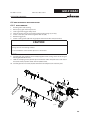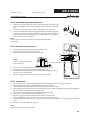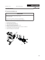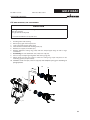
1
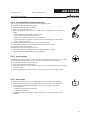
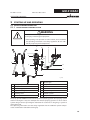
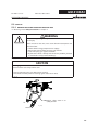
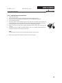
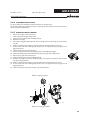
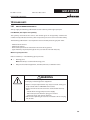
Translation of the original Operating manual GM 4100AC Edition 12/2008 AirCoat Spray gun for flat - and round jet nozzles B_02254 II 2G X (Atex 95) EDITION 12/2008 PART NO. DOC394821 GM 4100AC OPERATING MANUAL Contents 1 1.1 1.2 ABOUT THESE INSTRUCTIONS Languages Warnings, notes and symbols in these instructions 5 5 5 2 2.1 2.1.1 2.1.2 2.1.3 2.2 2.2.1 2.2.2 2.2.3 2.2.4 2.2.5 2.2.6 2.3 2.4 2.4.1 2.4.2 2.4.3 2.4.4 2.5 GENERAL SAFETY INSTRUCTIONS Safety instructions for the operator Electrical equipment Personnel qualifications A safe work environment Safety instructions for staff Safe handling of WAGNER spray units Earth the unit Paint hoses Cleaning Handling hazardous liquids, varnishes and paints Touching hot surfaces Correct use Use in hazardous locations Correct use Explosion protection identification Maximum surface temperature Maximum surface temperature German regulations and guidelines 6 6 6 6 6 6 7 7 7 8 8 8 8 9 9 9 9 9 9 3 3.1 3.2 3.3 PRODUCT LIABILITY AND WARRANTY Important notes on product liability Warranty CE-conformity 10 10 10 11 4 4.1 4.1.1 4.2 4.2.1 4.2.2 4.2.3 4.2.4 4.3 4.3.1 4.3.2 4.4 4.4.1 4.4.2 DESCRIPTION Fields of application, using in accordance with the instructions Processing materials Extent of delivery Variant for application range up to 16 MPa; 160 bar; 2320 psi Variant for application range up to 25 MPa, 250 bar, 3625 psi Standard equipments Spray gun configuration Data Materials of the parts transporting paint Technical data Functional description Design of spray gun Functions of the gun 12 12 12 12 12 12 12 13 14 14 14 15 15 15 5 5.1 5.1.1 5.1.2 5.1.3 5.1.4 STARTING UP AND OPERATING Installation and connection Typical AirCoat spraying system Ventilation of the spray booth Air supply Fluid (paint) hoses 16 16 16 17 17 17 3 EDITION 12/2008 PART NO. DOC394821 GM 4100AC OPERATING MANUAL Contents 5.1.5 5.2 5.3 5.3.1 5.3.2 5.4 5.4.1 5.4.2 5.4.3 5.4.4 5.4.5 Earthing Preparation of paints Start up General rules for handling the spray gun Preparation for starting up Works Start-up for spraying AirCoat Adjusting the spray pattern Replacing AirCoat nozzle Cleaning aircoat nozzle Eliminate nozzle clogging 18 18 19 19 20 21 21 21 22 23 23 6.0 6.1 6.2 6.3 6.4 6.4.1 6.4.2 6.4.3 6.4.4 6.5 6.6 MAINTENANCE Finishing work and cleaning Replacing the material hose or air hose Changing or cleaning Filter insert Replacing parts on the valve rod Disassembling Replacement of valve rocker seals Replacing the rod seal (35) Assembling Replacing the nozzle seal Replacing the „air“ sealing ring 24 25 26 27 28 28 29 29 29 30 31 7 TROUBLE SHOOTING AND SOLUTION 32 9 9.1 9.1.1 9.1.2 9.2 9.3 9.4 9.5 9.6 ACCESSORIES Round-jet nozzle cap Nozzle inserts RXX Nozzle screwed connection complete AirCoat nozzles ACF3000 Air caps Swivels and filter Hoses Miscellaneous 33 33 33 33 34 36 36 37 37 10 10.1 10.2 SPARE PARTS How to order spare parts? Spare parts list GM 4100AC 38 38 39 4 EDITION 12/2008 GM 4100AC PART NO. DOC394821 OPERATING MANUAL 1 ABOUT THESE INSTRUCTIONS 4HISOPERATINGMANUALCONTAINSINFORMATIONONTHEOPERATIONREPAIRANDMAINTENANCEOF THEUNIT !LWAYSOBSERVETHESEINSTRUCTIONSWHENOPERATINGTHEUNIT 4HISEQUIPMENTCANBEDANGEROUSIFITISNOTOPERATEDINACCORDANCEWITHTHISMANUAL #OMPLIANCE WITH THESE INSTRUCTIONS CONSTITUTES AN INTEGRAL COMPONENT OF THE WARRANTY AGREEMENT 1.1 LANGUAGES 4HISOPERATINGMANUALISAVAILABLEINTHEFOLLOWINGLANGUAGES ,ANGUAGE 0ART.O ,ANGUAGE 'ERMAN 394820 %NGLISH &RENCH 2301121 $UTCH )TALIAN 2301118 3PANISH $ANISH 2301125 3WEDISH 1.2 0ART.O 394821 2301122 2301119 2301129 WARNINGS, NOTES AND SYMBOLS IN THESE INSTRUCTIONS Warning instructions in this manual point out particular dangers to users and equipment and state measures for avoiding the hazard. These warning instructions fall into the following categories: DANGER Danger - imminent danger. Non-observance will result in death, serious injury and serious material damage. This line warns of the hazard! Possible consequences of failing to observe the warning instructions. The signal word points out the hazard level. SIHI_0100_GB The measures for preventing the hazard and its consequences. WARNING Warning - possible danger. Non-observance can result in death, serious injury and serious material damage. This line warns of the hazard! Possible consequences of failing to observe the warning instructions. The signal word points out the hazard level. SIHI_0103_GB The measures for preventing the hazard and its consequences. CAUTION Caution - a possibly hazardous situation. Non-observance can result in minor injury. This line warns of the hazard! Possible consequences of failing to observe the warning instructions. The signal word points out the hazard level. The measures for preventing the hazard and its consequences. SIHI_0101_GB Caution - a possibly hazardous situation. Non-observance can cause material damage. SIHI_0102_GB CAUTION This line warns of the hazard! Possible consequences of failing to observe the warning instructions. The signal word points out the hazard level. The measures for preventing the hazard and its consequences. Note - provide information on particular characteristics and how to proceed. 5 EDITION 12/2008 PART NO. DOC394821 GM 4100AC OPERATING MANUAL 2 GENERAL SAFETY INSTRUCTIONS 2.1 SAFETY INSTRUCTIONS FOR THE OPERATOR +EEPTHESEOPERATINGINSTRUCTIONSTOHANDNEARTHEUNITATALLTIMES !LWAYSFOLLOWLOCALREGULATIONSCONCERNINGOCCUPATIONALSAFETYANDACCIDENTPREVEN TION 2.1.1 ELECTRICAL EQUIPMENT %LECTRICALPLANTANDUNIT 4O BE PROVIDED IN ACCORDANCE WITH THE LOCAL SAFETY REQUIREMENTS WITH REGARD TO THE OPERATINGMODEANDAMBIENTINmUENCES -AYONLYBEMAINTAINEDBYSKILLEDELECTRICIANSORUNDERTHEIRSUPERVISION -USTBEOPERATEDINACCORDANCEWITHTHESAFETYREGULATIONSANDELECTROTECHNICALREGU LATIONS -USTBEREPAIREDIMMEDIATELYINTHEEVENTOFPROBLEMS -USTBEPUTOUTOFOPERATIONIFTHEYPOSEAHAZARD -USTBEDEENERGIZEDBEFOREWORKISCOMMENCEDONACTIVEPARTS)NFORMSTAFFABOUT PLANNEDWORKOBSERVEELECTRICALSAFETYREGULATIONS 2.1.2 PERSONNEL QUALIFICATIONS %NSURETHATTHEUNITISOPERATEDANDREPAIREDONLYBYTRAINEDPERSONS 2.1.3 A SAFE WORK ENVIRONMENT %NSURETHATTHEmOOROFTHEWORKINGAREAISANTISTATICINACCORDANCEWITH%.0ART eMEASUREMENTINACCORDANCEWITH$). %NSURETHATALLPERSONSWITHINTHEWORKINGAREAWEARANTISTATICSHOESEGSHOESWITH LEATHERSOLES %NSURETHATDURINGSPRAYINGPERSONSWEARANTISTATICGLOVESSOTHATTHEYAREEARTHEDVIA THEHANDLEOFTHESPRAYGUN #USTOMERTOPROVIDEPAINTMISTEXTRACTIONSYSTEMSCONFORMINGTOLOCALREGULATIONS %NSURETHATTHEFOLLOWINGCOMPONENTSOFASAFEWORKINGENVIRONMENTAREAVAILABLE n-ATERIALAIRHOSESADAPTEDTOTHEWORKINGPRESSURE n0ERSONALSAFETYEQUIPMENTBREATHINGANDSKINPROTECTION %NSURE THAT THERE ARE NO IGNITION SOURCES SUCH AS NAKED mAME GLOWING WIRES OR HOT SURFACESINTHEVICINITY$ONOTSMOKE 2.2 SAFETY INSTRUCTIONS FOR STAFF !LWAYSFOLLOWTHEINFORMATIONINTHESEINSTRUCTIONSPARTICULARLYTHEGENERALSAFETYIN STRUCTIONSANDTHEWARNINGINSTRUCTIONS !LWAYSFOLLOWLOCALREGULATIONSCONCERNINGOCCUPATIONALSAFETYANDACCIDENTPREVEN TION 6 EDITION 12/2008 PART NO. DOC394821 GM 4100AC OPERATING MANUAL 2.2.1 SAFE HANDLING OF WAGNER SPRAY UNITS The spray jet is under pressure and can cause dangerous injuries. Avoid injection of paint or cleaning agents: Never point the spray gun at people. Never reach into the spray jet. Before all work on the unit, in the event of work interruptions and functional faults: – Switch off the energy/compressed air supply. – Secure the spray gun against actuation. – Relieve the pressure from the spray gun and unit. – By functional faults: Identify and correct the problem, proceed as described in chap. „Trouble shooting“. In the event of skin injuries caused by paint or cleaning agents: Note down the paint or cleaning agent that you have been using. Consult a doctor immediately. Avoid danger of injury through recoil forces: Ensure that you have a firm footing when operating the spray gun. Only hold the spray gun briefly in any one position. 2.2.2 EARTH THE UNIT Electrostatic charges can occur on the unit due to the electrostatic charge and the flow speed involved in spraying.These can cause sparks and flames upon discharge. Ensure that the unit is always earthed. Earth the work pieces to be coated. Ensure that all persons inside the working area are earthed, e.g. that they are wearing antistatic shoes. When spraying, wear antistatic gloves to earth yourself via the spray gun handle. 2.2.3 PAINT HOSES %NSURETHATTHEHOSEMATERIALISCHEMICALLYRESISTANTTOTHESPRAYEDMATERIALS %NSURETHATTHEMATERIALHOSEISSUITABLEFORTHEPRESSUREGENERATEDINTHEUNIT %NSURETHATTHEFOLLOWINGINFORMATIONISVISIBLEONTHEHIGHPRESSUREHOSE n -ANUFACTURER n 0ERMISSIBLEOPERATINGOVERPRESSURE n $ATEOFMANUFACTURE 4HEELECTRICALRESISTANCEOFTHECOMPLETEHIGHPRESSUREHOSEMUSTBELESSTHAN -/HM 7 EDITION 12/2008 PART NO. DOC394821 GM 4100AC OPERATING MANUAL 2.2.4 CLEANING $EENERGIZETHEUNITELECTRICALLY $ISCONNECTTHEPNEUMATICSUPPLYLINE 2ELIEVETHEPRESSUREFROMTHEUNIT %NSURETHATTHEmASHPOINTOFTHECLEANINGAGENTISATLEAST+ABOVETHEAMBIENTTEM PERATURE 4OCLEANUSEONLYSOLVENTFREECLOTHSANDBRUSHES.EVERUSEHARDOBJECTSORSPRAYON CLEANINGAGENTSWITHAGUN !NEXPLOSIVEGASAIRMIXTUREFORMSINCLOSEDCONTAINERS 7HENCLEANINGUNITSWITHSOLVENTSNEVERSPRAYINTOACLOSEDCONTAINER %ARTHTHECONTAINER 2.2.5 HANDLING HAZARDOUS LIQUIDS, VARNISHES AND PAINTS 7HENPREPARINGORWORKINGWITHPAINTANDWHENCLEANINGTHEUNITFOLLOWTHEWORK INGINSTRUCTIONSOFTHEMANUFACTUREROFTHEPAINTSSOLVENTSANDCLEANINGAGENTSBEING USED 4AKE THE SPECIlED PROTECTIVE MEASURES IN PARTICULAR WEAR SAFETY GOGGLES PROTECTIVE CLOTHINGANDGLOVESASWELLASHANDPROTECTIONCREAMIFNECESSARY 5SEAMASKORBREATHINGAPPARATUSIFNECESSARY &ORSUFlCIENTHEALTHANDENVIRONMENTALSAFETY/PERATETHEUNITINASPRAYBOOTHORON ASPRAYINGWALLWITHTHEVENTILATIONEXTRACTIONSWITCHEDON 7EARSUITABLEPROTECTIVECLOTHINGWHENWORKINGWITHHOTMATERIALS 2.2.6 TOUCHING HOT SURFACES 4OUCHHOTSURFACESONLYIFYOUAREWEARINGPROTECTIVEGLOVES 7HENOPERATINGTHEUNITWITHACOATINGMATERIALWITHATEMPERATUREOF²#²& )DENTIFYTHEUNITWITHAWARNINGLABELTHATSAYSu7ARNINGHOTSURFACEh /RDER.O )NFORMATIONLABEL 3AFETYLABEL 2.3 CORRECT USE 7!'.%2ACCEPTSNOLIABILITYFORANYDAMAGEARISINGFROMINCORRECTUSE 5SETHEUNITONLYTOWORKWITHTHEMATERIALSRECOMMENDEDBY7!'.%2 /PERATETHEUNITONLYASANENTIREUNIT $ONOTDEACTIVATESAFETYEQUIPMENT 5SEONLY7!'.%2ORIGINALSPAREPARTSANDACCESSORIES 8 EDITION 12/2008 PART NO. DOC394821 GM 4100AC OPERATING MANUAL 2.4 USE IN HAZARDOUS LOCATIONS 2.4.1 CORRECT USE 4HEUNITISSUITABLEFORWORKINGLIQUIDMATERIALSINACCORDANCEWITHTHECLASSIlCATIONINTO EXPLOSIONCLASSES 2.4.2 EXPLOSION PROTECTION IDENTIFICATION As defined in the Directive 94/9/CE (ATEX 95), the unit is suitable for use in areas where there is an explosion hazard. II 2G X CE: Ex: II: 2: G: X: Communautés Européennes Symbol for explosion protection Unit class II Category 2 (Zone 1) Ex-atmosphere gas See: "Special Notes" in the operating manual 2.4.3 MAXIMUM SURFACE TEMPERATURE X: The maximum surface temperature corresponds to the permissible material temperature. This and the permissible ambient temperature can be found in the Technical Data. 2.4.4 MAXIMUM SURFACE TEMPERATURE 3AFEHANDLINGOF7!'.%2SPRAYUNITS -ECHANICALSPARKSCANFORMIFTHEUNITCOMESINTOCONTACTWITHMETAL )NANEXPLOSIVEATMOSPHERE $ONOTKNOCKORPUSHTHEUNITAGAINSTSTEELORRUSTYIRON $ONOTDROPTHESPRAYGUN 5SEONLYTOOLSTHATAREMADEOFAPERMITTEDMATERIAL )GNITIONTEMPERATUREOFTHECOATINGMATERIAL %NSURETHATTHEIGNITIONTEMPERATUREOFTHECOATINGMATERIALISABOVETHEMAXIMUM SURFACETEMPERATURE -EDIUMSUPPORTINGATOMIZING 4OATOMIZETHEMATERIALUSEONLYWEAKLYOXIDIZINGGASESEGAIR #LEANING )F THERE ARE DEPOSITS ON THE SURFACES THE UNIT MAY FORM ELECTROSTATIC CHARGES &LAMES OR SPARKSCANFORMIFTHEREISADISCHARGE 2EMOVEDEPOSITSFROMTHESURFACESTOMAINTAINCONDUCTIVITY 2.5 GERMAN REGULATIONS AND GUIDELINES see chapter 3.3 9 EDITION 12/2008 PART NO. DOC394821 GM 4100AC OPERATING MANUAL 3 PRODUCT LIABILITY AND WARRANTY 3.1 IMPORTANT NOTES ON PRODUCT LIABILITY !SARESULTOFAN%#REGULATIONEFFECTIVEASFROM*ANUARYTHEMANUFACTURERSHALL ONLYBELIABLEFORHISPRODUCTIFALLPARTSCOMEFROMHIMORAREAPPROVEDBYHIMANDIFTHE DEVICESAREPROPERLYlTTEDOPERATEDANDMAINTAINED )FOTHERMAKESOFACCESSORYANDSPAREPARTSAREUSEDTHEMANUFACTURER@SLIABILITYCOULDBE FULLYORPARTIALLYNULLANDVOID 4HEUSAGEOFORIGINAL7!'.%2ACCESSORIESANDSPAREPARTSGUARANTEESTHATALLSAFETYRE GULATIONSAREOBSERVED 3.2 WARRANTY 4HISUNITISCOVEREDBYOURWARRANTYONTHEFOLLOWINGTERMS 7EWILLATOURDISCRETIONREPAIRORREPLACEFREEOFCHARGEALLPARTSWHICHWITHINMONTHS INSINGLESHIFTMONTHSINSHIFTORMONTHSINSHIFTOPERATIONFROMDATEOFRECEIPTBY THE0URCHASERAREFOUNDTOBEWHOLLYORSUBSTANTIALLYUNUSABLEDUETOCAUSESPRIORTOTHE SALEINPARTICULARFAULTYDESIGNDEFECTIVEMATERIALSORPOORWORKMANSHIP 4HETERMSOFTHEWARRANTYAREMETATOURDISCRETIONBYTHEREPAIRORREPLACEMENTOFTHE UNITORPARTSTHEREOF4HERESULTINGCOSTSINPARTICULARSHIPPINGCHARGESROADTOLLSLABOUR ANDMATERIALCOSTSWILLBEBORNEBYUSEXCEPTWHERETHESECOSTSAREINCREASEDDUETOTHE SUBSEQUENTSHIPMENTOFTHEUNITTOALOCATIONOTHERTHANTHEADDRESSOFTHEPURCHASER 4HISWARRANTYDOESNOTCOVERDAMAGECAUSEDBY 5NSUITABLE OR IMPROPER USE FAULTY INSTALLATION OR COMMISSIONING BY THE PURCHASER OR A THIRD PARTY NORMAL WEAR NEGLIGENT HANDLING DEFECTIVE MAINTENANCE UNSUITABLE COATING PRODUCTS SUBSTITUTE MATERIALS AND THE ACTION OF CHEMICAL ELECTROCHEMICAL OR ELECTRICAL AGENTSEXCEPTWHENTHEDAMAGEISATTRIBUTABLETOUS !BRASIVE COATING PRODUCTS SUCH AS REDLEAD EMULSIONS GLAZES LIQUID ABRASIVES ZINC DUST PAINTSANDSIMILARREDUCETHESERVICELIFEOFVALVESPACKINGSSPRAYGUNSNOZZLESCYLINDERS PISTONSETC!NYWEARRESULTINGFROMTHEAFOREMENTIONEDCAUSESISNOTCOVEREDBYTHIS WARRANTY #OMPONENTSNOTMANUFACTUREDBY7AGNERARESUBJECTTOTHEWARRANTYTERMSOFTHEORIGI NALMAKER 4HEREPLACEMENTOFAPARTDOESNOTEXTENDTHEWARRANTYPERIODOFTHEUNIT 4HEUNITSHOULDBEINSPECTEDIMMEDIATELYUPONRECEIPT 4OAVOIDLOSSWARRANTYANIYAPPARENTDEFECTSHOULDBENOTIlEDTOUSORTHEDEALERINWRI TINGWITHINDAYSFROMDATEOFSALEOFTHEUNIT 4HERIGHTTOCOMMISSIONWARRANTYSERVICESTOATHIRDPARTYISRESERVED 7ARRANTYCLAIMSARESUBJECTTOPROOFOFPURCHASEBYSUBMITTINGANINVOICEORDELIVERYNOTE )FANINSPECTIONlNDSDAMAGENOTCOVEREDBYTHEPRESENTWARRANTYTHEREPAIRWILLBECAR RIEDOUTATTHEEXPENSEOFTHEPURCHASER .OTETHATTHISWARRANTYDOESNOTINANYWAYRESTRICTLEGALLYENTITLEDCLAIMSORTHOSECONTRAC TUALLYAGREEDTOINOURGENERALTERMSANDCONDITIONS *7AGNER!' 10 EDITION 12/2008 PART NO. DOC394821 GM 4100AC OPERATING MANUAL 3.3 CE-CONFORMITY Herewith we declare that the supplied version of GM 4100AC 16 MPa GM 4100AC 25 MPa Complies with the following guidelines: 98/37/EG 94/9/EG Applied standards, in particular: DIN EN ISO 12100-1, 2004-04 DIN EN ISO 14121,2007-12 DIN EN ISO 12100-2, 2004-04 DIN EN ISO 3746, 1995-12 DIN EN 1127-1, 2008-02 DIN EN 13463-1, 2002-04 DIN EN 1953, 1998-12 DIN EN ISO 13732-1, 2006-12 Applied national technical standards and specifications, in particular: a) b) c) d) e) BGR 500 BGR 500 BGR 104 BGR 132 BGR 180 f ) BGI 740 g) ZH 1/406 Part 2, Chap. 2.29„Using coating materials“ Part 2, Chap. 2.36„Working with liquid ejection devices“ Explosion protection rules Avoiding ignition risks Setting up for cleaning with solvents for cleaning workpieces with solvents Painting rooms and equipment Guidelines for liquid ejection devices Note: All titles can be ordered from Heymanns Publishing House in Cologne or of the Internet download. CE Certificate of Conformity The certificate is enclosed with this product.The certificate of conformity can be reordered from your WAGNER representative, quoting the product and serial number. Part number: 394891 11 EDITION 12/2008 PART NO. DOC394821 GM 4100AC OPERATING MANUAL 4 DESCRIPTION 4.1 FIELDS OF APPLICATION, USING IN ACCORDANCE WITH THE INSTRUCTIONS The gun is suitable for atomising liquid materials, particularly coating materials, using the AirCoat process. 4.1.1 PROCESSING MATERIALS Top-coat paints, primer paints, corrosion protection solvents, textured paints, lyes, staining solvents, clear paints, parting solvents, etc. on a solvent or water basis. If you want to spray other working materials than the aforementioned, turn please to a Wagner agency. WARNING Hot coating substances! Burns Wear antistatic protective gloves. When operating the unit with a coating material with a temperature greater than 43°C; 109.4°F: Identify the unit with a warning sticker "Warning - hot surface". SIHI_0019_GB Note: 4.2 Please contact your local WAGNER dealer and the paint manufacturer if you encounter application problems. EXTENT OF DELIVERY These AirCoat gun is available in two different variants. The nozzle size depends on the paint and on the application, Therefore the air cap and the nozzle are not included in the scope of supply. For a gun accessories look in chapter 9. 4.2.1 VARIANT FOR APPLICATION RANGE UP TO 16 MPA; 160 BAR; 2320 PSI Qty Part-No. Description 1 394002 GM 4100AC 16 MPa; NPSM1/4“ Paint connection 4.2.2 VARIANT FOR APPLICATION RANGE UP TO 25 MPA, 250 BAR, 3625 PSI Qty Part-No. Description 1 394012 GM 4100AC 25 MPa ; NPSM1/4“ Paint connection 4.2.3 STANDARD EQUIPMENTS The standard equipment includes: 394002 394012 AirCoat hand gun GM 4100AC Qty Qty Part-No. Description 1 1 394891 CE-conformity 1 1 394820 1 1 see chap. 1 Operating manual German Operating manual for the other language For special versions the delivery note applies. 12 EDITION 12/2008 GM 4100AC PART NO. DOC394821 OPERATING MANUAL 4.2.4 SPRAY GUN CONFIGURATION A B CCC B_02663 Basis number GM 4100AC 0 3 9 4 0 1 0 - A B C C C -> Key - 1 1 4 1 1 -> For example: Part number Table A: Maxi. material pression selection 1 160 bar; 16 MPa; 2320 psi 2 250 bar; 25 MPa; 3625 psi Table B: Air cap selection 1 Suitable for low viscosity paints (red) 2 Suitable for high viscosity paints (blue) Table CCC: AirCoat nozzle selection ACF3000 CCC = the last three digits of the article number -> 0379CCC 107 1 = spray angle x 10 = 100. 07 = diameter of bore in mm/1000 (0.007 mm) 411 4 = spray angle x 10 = 400. 11 = diameter of bore in mm/1000 (0.011 mm) 317 3 = spray angle x 10 = 300. 17 = diameter of bore in mm/1000 (0.017 mm) 625 6 = spray angle x 10 = 600. 25 = diameter of bore in mm/1000 (0.025 mm) 835 8 = spray angle x 10 = 800. 35 = diameter of bore in mm/1000 (0.035 mm) The complete flat-jet nozzle range is described in chapter 9.2. 13 EDITION 12/2008 GM 4100AC PART NO. DOC394821 OPERATING MANUAL 4.3 DATA 4.3.1 MATERIALS OF THE PARTS TRANSPORTING PAINT Metal Plastic Tungsten carbide Stainless steel 1.4305 POM FPM Stainless steel 1.4301 Stainless steel 1.4104 PTFE PA 4.3.2 TECHNICAL DATA AirCoat spray gun Description Units 394002 394012 Maxi. air inlet pressure MPa/ psi/ bar 0.8/ 120/ 8 Maxi. material pressure MPa/ psi/ bar 16/ 2320/ 160 25/ 3625/ 250 Paint hose connection Inches NPSM1/4 Air connection Inches G1/4“ Filter Mesh 100 Weight g/ oz 437/ 15.4 pH range of the material pH 3.5 - 9.0 Maxi. temperature material °C/ °F 55/ 131 Maxi. temperature air °C/ °F 43/ 109 Sound level at 0.3 MPa; 3 bar; 43.5 dB(A) < 82 psi air pressure and 11 MPa; 110 bar; 1549 psi material pressure *** ** Filter types see chapter 9.6 *** A rated sound pressure level measured at 0.5 m distance according to DIN EN ISO 37461995. C A D Dim. mm inch A 173 6.81 B 206 8.11 C 48 1.89 D 152 5.98 E 39 1.54 F - NPSM1/4“ G - G1/4“ E B Dimensions G B_02258 F 14 EDITION 12/2008 GM 4100AC PART NO. DOC394821 OPERATING MANUAL 4.4 FUNCTIONAL DESCRIPTION 4.4.1 DESIGN OF SPRAY GUN B C A J I E D H L F K B_02255 G Description A Suspension hook B Fan air regulator C Tension nut D Trigger E Trigger safety F Air connection G Paint connection H Union nut with nozzle guard I Nozzle / Air cap J Gun housing K Filter housing L Handle tube 4.4.2 FUNCTIONS OF THE GUN Pulling the trigger (D) approximately 1/2 way opens the air valve allowing atomising and shaping-air to flow through the air cap. When the trigger is pulled further, more resistance is felt and the material valve is opened. The atomising air control (B) adjusts the total quantity of air flowing trough the spray gun. The spray gun is rendered safe with the trigger safety catch (E). (Turn the trigger safety catch in the spraying direction and fasten in the groove). 15 EDITION 12/2008 GM 4100AC PART NO. DOC394821 OPERATING MANUAL 5 STARTING UP AND OPERATING 5.1 INSTALLATION AND CONNECTION 5.1.1 TYPICAL AIRCOAT SPRAYING SYSTEM WARNING Incorrect installation/operation! Risk of injury and damage to equipment When putting into operation and for all work, read and follow the operating instructions and safety regulations for the additionally required system components. SIHI_0050_GB E D F G C B M I K H A J L B_02259 G AirCoat gun A Paint-pump H HV-paint hose B Compressed air shut off valve I HV-filter/Relief valve C Pressure regulator J Relief D Air pressure regulator with filter K Stand trolley E Earthing cable L Suction system Air hose, el. conductive M Compressed air main F The pray gun GM 4100AC must be used a part of a spraying system. The spraying system shown in the figure is only one example of an Aircoat spraying system. It is not an actual system design. Contact your Wagner distributor for assistance in designing a system to meet your needs. The operating instructions and the safety regulations for the additional system components used must be read before starting-up. 16 EDITION 12/2008 PART NO. DOC394821 GM 4100AC OPERATING MANUAL 5.1.2 VENTILATION OF THE SPRAY BOOTH WARNING Toxic and/or flammable vapor mixtures! Risk of poisoning and burns Operate the unit in a spraying booth approved for the working materials. -or Operate the unit on an appropriate spraying wall with the ventilation (extraction) switched on. Observe national and local regulations for the outgoing air speed. SIHI_0028_GB 5.1.3 AIR SUPPLY The use of an air filter with the air regulator (D) ensures that only dry, clean atomising air gets into the spray gun! Dirt and moisture in the atomising air reduce the spraying quality and the appearance of the finished piece. 5.1.4 FLUID (PAINT) HOSES CAUTION Impurities in the spraying system! Spray gun blockage, materials harden in the spraying system Flush the spray gun and paint supply with a suitable cleaning agent. SIHI_0001_GB DANGER Bursting hose, bursting threaded joints! Danger to life from injection of material Ensure that the hose material is chemically resistant. Ensure that the spray gun, threaded joints and material hose between the unit and the spray gun is suitable for the pressure generated in the unit. Ensure that the following information can be seen on the highpressure hose: - Manufacturer - Permissible operating pressure - Date of manufacture. SIHI_0029_GB 17 EDITION 12/2008 PART NO. DOC394821 GM 4100AC OPERATING MANUAL 5.1.5 EARTHING 7!2.).' $ISCHARGE OF ELECTROSTATICALLY CHARGED COMPONENTS IN ATMO SPHERESCONTAININGSOLVENTS %XPLOSIONHAZARDFROMELECTROSTATICSPARKSORmAMES %ARTHALLUNITCOMPONENTS %ARTHTHEWORKPIECESBEINGPAINTED 3)()??'" WARNING Heavy paint mist if earthing is insufficient! Risk of poisoning Insufficient paint application quality Earth all unit components. Earth the workpieces being painted. SIHI_0003_GB Any material containers and the unit must be connected by a potential equalisation (earth) cable. 5.2 PREPARATION OF PAINTS The viscosity of the paints is of great importance. The best spraying results are obtained with values between 80 and 260 milli Pascal x Sec (mPas. Please also read the technical data sheet for the paint for optimal processing, viscosity adjustment and intermixing of the material. 18 EDITION 12/2008 PART NO. DOC394821 GM 4100AC OPERATING MANUAL 5.3 START UP 5.3.1 GENERAL RULES FOR HANDLING THE SPRAY GUN ➞ Observe general safety instructions in chapter 2. WARNING Unintentional putting into operation! Risk of injury Before all work on the unit, in the event of work interruptions and functional faults: Switch off the energy/compressed air supply. Relieve the pressure from the spray gun and unit. Secure the spray gun against actuation. By functional faults: Identify and correct the problem, proceed as described in chap„Trouble shooting“. SIHI_0065_GB CAUTION Cleaning agent in the air duct! Functional faults caused by swollen seals Always point the spray gun down when cleaning. Ensure that neither paint nor cleaning agent enters the air duct. SIHI_0005_GB Trigger safety catch in on (safe) position Air B_02260 Material 19 EDITION 12/2008 PART NO. DOC394821 GM 4100AC OPERATING MANUAL 5.3.2 PREPARATION FOR STARTING UP 1. 2. 3. 4. 5. Secure the spray gun. Connect material hose to the spray gun and material supply system. Connect air hose to spray gun and to oil-free, dry air supply with regulator. Insert suitable gun filter. Place the nozzle into the nozzle seal. Fit the air cap over the nozzle, ensuring that the location flats (X) are in line. Fit the union nut with nozzle guard and tighten by hand. 6. Visually check the permissible pressures for all the system components. 7. Make sure that the unit and all other conductive parts within the work area are earthed. 8. Set material pressure 100 bar; 10 MPa; 1450 psi and use a suitable medium (solvent or water) to check that connections do not leak x B_02261 Note: Pull the trigger and then release, checking that the gun closes cleany. 9. Relieve spray gun and unit pressure and secure the spray gun. 20 EDITION 12/2008 PART NO. DOC394821 GM 4100AC OPERATING MANUAL 5.4 WORKS 5.4.1 START-UP FOR SPRAYING AIRCOAT 1. Start up with material supply set to approx. 8 MPa; 80 bar; 1160 psi operating pressure. 2. Spray (release trigger safety catch and pull trigger) and check the atomisation. 3. Set the fluid pressure to the point where a further increase in fluid pressure would significantly improve fluid atomization. 4. Open air pressure controller for the atomizer air and adjust so as to achieve optimal atomization. (The interrelation between spray pattern and atomizer air is shown in the figure below). 5. Use the shaping air controller on the gun to adjust the shaping air to atomizer air ratio, until the optimal spray pattern is achieved. Note: Repeat point 4 and 5 until the optimum spray pattern is reached (process iterative). Spray pattern B_00071 No atomizing air Too little atomizing air Correct amount of air Note The paint output volume can be changed by: Changing the material pressure or Fitting another flat jet nozzle (see chap. 5.4.3 and chap. 9). • • 5.4.2 ADJUSTING THE SPRAY PATTERN The spray pattern can be adjusted to suit the object being sprayed using the fan air regulator. The illustration below shows the influence of the shaping air regulator on the spraying pattern. Other nozzle sizes can be used to obtain larger or smaller spraying patterns. Shaping air fully open Shaping air fully closed B_02262 21 EDITION 12/2008 GM 4100AC PART NO. DOC394821 OPERATING MANUAL 5.4.3 REPLACING AIRCOAT NOZZLE CAUTION Defective AirCoat nozzle! Insufficient paint application quality Do not use sharp-edged objects to treat hard metal on the AirCoat nozzle. SIHI_0020_GB 1. 2. 3. 4. 5. Relieve spray gun and unit pressure. Secure gun with trigger safety catch. Screw off the union nut (A). Remove air cap (B). Press AirCoat nozzle (C) out of the air cap (B) by hand and brush with cleaning solvent until all remaining paint has been dissolved. 6. Assembly: Place AirCoat nozzle (C) in nozzle seal (D). 7. Fit the air cap (B) over the nozzle (C), ensuring that the location flats (X) are in line. 8. Fit the union nut with nozzle guard (A) and tighten by hand. x B_02261 D B C A B_02263 22 EDITION 12/2008 GM 4100AC PART NO. DOC394821 OPERATING MANUAL 5.4.4 CLEANING AIRCOAT NOZZLE For disassembly and assembly of AirCoat nozzles see chapter 5.4.3. The AirCoat nozzle (C) can be placed into a cleaning solvent which has been recommended by the paint manufacturer. 5.4.5 1. 2. 3. 4. 5. 6. 7. 8. 9. 10. 11. 12. 13. 14. 15. 16. ELIMINATE NOZZLE CLOGGING Relieve spray gun and unit pressure. Secure gun with trigger safety catch. Unscrew the union nut with nozzle guard (A). Remove air cap (B). Pull out the clogged nozzle (C) from the air cap (B), reverse it and replace it into nozzle seal (D). Refit air cap (B) on the nozzle (C), ensuring that the location flats (X) are in line. Fit the union nut with nozzle guard (A) over the air cap (B) onto the spray gun and tighten by hand. Switch the material pressure back on. Turn the safety catch to the spraying position and briefly pull trigger. When the blockage has been flushed out secure the gun with safety catch. Relieve spray gun and unit pressure Unscrew the union nut with nozzle guard (A). Remove air cap (B) and reverse nozzle (C) again. Clean nozzle and replace on the nozzle seal (D) in spray position. Refit air cap (B) on the nozzle (C), ensuring that the location flats (X) are in line. Fit the union nut with nozzle guard (A) over the air cap (B) onto the spray gun and tighten by hand. Switch the material pressure and the air pressure back on. x B_02261 Nozzle in „spray“ position D B C A B_02264 Nozzle in „cleaning“ position 23 EDITION 12/2008 PART NO. DOC394821 GM 4100AC OPERATING MANUAL 6.0 MAINTENANCE ➞ Observe general safety instructions in chapter 2. The spray gun and the unit must be cleaned every day. Use only the cleaning solvent recommended by the material manufacture. CAUTION Cleaning agent in the air duct! Functional faults caused by swollen seals Never immerse the spray gun in cleaning agent. SIHI_0066_GB WARNING Incorrect maintenance/repair! Risk of injury and damage to the equipment Repairs and part replacement may only be carried out by specially trained staff or a WAGNER service center. Before all work on the unit and in the event of work interrup tions: - Switch off the energy/compressed air supply. - Relieve the pressure from the spray gun and unit. - Secure the spray gun against actuation. Observe the operating and service instructions when carrying out all work. SIHI_0004_GB 24 EDITION 12/2008 PART NO. DOC394821 GM 4100AC OPERATING MANUAL 6.1 FINISHING WORK AND CLEANING DANGER Exploding gas/ air mixture! Danger to life from flying parts and burns Never spray into a closed container. Earth the container. SIHI_0008_GB CAUTION Cleaning agent in the air duct! Functional faults caused by swollen seals Always point the spray gun down when cleaning. Ensure that neither paint nor cleaning agent enters the air duct. SIHI_0005_GB 7!2.).' %XPLOSIVEATMOSPHERE %XPLOSIVEGASESAREPRODUCEDWHENALUMINIUMCOMESINTOCONTACT WITHHALOGENIZEDHYDROCARBONS 4OCLEANALUMINIUMDONOTUSELIQUIDSCONTAININGHALOGENIZED HYDROCARBONS 3)()??'" Note: Methylene chloride is not recommended as a flushing or cleaning solvent with this gun or any system components. 1. 2. 3. 4. 5. Relieve spray gun and unit pressure. Secure gun with trigger safety catch. Connect cleaning supply. Remove AirCoat nozzle and clean separately (see chap 5.4.3). Pressurize the cleaning supply to approx. 4 MPa; 40 bar; 580 psi and thoroughly flush the spray gun. 6. Relieve spray gun and unit pressure. 7. Secure gun with trigger safety catch. 8. Clean gun body with a cleaning agent recommended by the manufacturer, and dry with a cloth. 25 EDITION 12/2008 GM 4100AC PART NO. DOC394821 OPERATING MANUAL 6.2 REPLACING THE MATERIAL HOSE OR AIR HOSE 1. Finishing work and cleaning. 2. Relieve spray gun and unit pressure. 3. Secure gun with trigger safety catch. Material hose 4. Place open-ended wrench SW A on flats of paint connection and counter hold. 5. Turn nut to the right with open-ended wrench SW D and unscrew material hose. Air hose 4. Place open-ended wrench SW D on flats of air connection and counter hold. 5. Turn nut to the right with open-ended wrench SW C and unscrew air hose. 6. Assembly: Fit the material hose respectively air hose by hand and tighten with 2 open-ended wrenches. D Counter hold C Counter hold A Note: Do not unscrew the filter housing. The nut must only be unscrewed by WAGNER- Service-Agency. B B_02265 B_02266 Description Wrench A Wrench B Wrench C GM 4100AC with filter NPS1/4“ SW 17 mm 0.669 inches SW 19 mm SW 17 mm 0.748 inches 0.669 inches Wrench D SW 14 mm 0.551 inches 26 EDITION 12/2008 PART NO. DOC394821 GM 4100AC OPERATING MANUAL 6.3 1. 2. 3. 4. 5. 6. 7. 8. 9. CHANGING OR CLEANING FILTER INSERT Finishing work and cleaning. Relieve spray gun and unit pressure. Secure gun with trigger safety catch. Place open-ended wrench A on flats of filter housing (30) and counter hold. Turn nut to the right with open-ended wrench B and unscrew pivot joint (32) with material hose. Remove the material filter (31). Clean the filter housing (30), filter socket (32) and edge filter with cleaning agent. Assembly: Fit the cleaned or new edge filter (31) into the filter socket (32). Fit filter socket with the material hose by hand and tighten with 2 open-ended wrenches. 30 Counter hold A 32 31 B_02272 B 27 EDITION 12/2008 GM 4100AC PART NO. DOC394821 OPERATING MANUAL 6.4 REPLACING PARTS ON THE VALVE ROD 6.4.1 1. 2. 3. 4. 5. 6. 7. DISASSEMBLING Finishing work and cleaning. Relieve spray gun and unit pressure. Secure gun with trigger safety catch. Unscrew spring cover (5) and remove compression springs (2) and (3). Loosen screw (22) and remove together with nut (20). Remove trigger (21). Loosen sealing screw (10) with single open-end wrench SW 7 mm; 0.28 inches. CAUTION Unsuitable tool! Damage to seals and sealing surfaces Do not hold the valve rod with pliers or a similar tool. SIHI_0006_GB 8. Carefully pull the complete valve rod (B) together with sealing screw out of the gun housing (A) toward the rear. 9. Hold the clamping sleeve (4) with open-end wrench SW 6 mm; 0.24 inches and loosen the collet chuck (18) with socket SW 2 mm; 0.08 inches. 10. Carefully pull the valve rod (34) out toward the front. Replace the relevant parts. B 5 2 A 3 20 21 4 18 19 22 10 12 11 34 50 51 B_02267 52 53 28 EDITION 12/2008 GM 4100AC PART NO. DOC394821 OPERATING MANUAL 6.4.2 REPLACEMENT OF VALVE ROCKER SEALS 1. Support valve tappet (50) with single open-end wrench SW 13 mm; 0.51 inch and unscrew cover (53) with single open-end wrench SW 7 mm; 0.28 inch. 2. Remove air valve seal (51) and seal (52) and replace with new seals. 3. Screw valve tappet (50) and cover (53) together by hand. Carefully tighten in small increments with open-end wrench SW 7 mm; 0.28 inch and SW 13 mm; 0.51 inch until a slight resistance is perceptible when moving the valve rod (34) in the valve tappet. Note: The seal (52) can be pulled out of the cover (53) with the help of an eye bolt. 6.4.3 50 51 52 53 B_02274 REPLACING THE ROD SEAL (35) 1. Carefully pull the rod seal (35) out of the gun housing. 2. Clean sealing surfaces in the gun housing. 3. Mount new rod seal (35) to the rod seal tool (84). 22 84 35 Note: Note installation position of the rod seal (35). 21 Spraying direction B_02688 4. Insert rod seal tool (84) together with rod seal (35) into the hole. 5. Fit trigger guard (21) with screw (22) to body of gun and 6. Carefully push the tool with the rod seal (35) over the trigger guard (21) into the recess in the housing. 7. Remove trigger guard (21), screw (22) and rod seal tool (84). B_02268 6.4.4 1. 2. 3. 4. 5. 6. 7. 8. 9. 10. ASSEMBLING Fit seal collar (11) to valve rod (14), together with inserted O-ring (12) and sealing screw (10). Push completely assembled valve tappet (19) onto valve rod (14). Insert preassembled valve rod into the collet chuck (18) as far as the stop. Fix clamping sleeve (4) with wrench size 6 mm; 0.24 inch, screw the preassembled valve rod to the clamping sleeve and tighten. (Socket SW 2 mm; 0.079 inch) Carefully insert the complete valve rod (B) into the gun housing. Screw in sealing screw (10) but do not tighten yet. Position trigger guard (21) and secure with screw (22) and nut (20). Insert compression springs (3) and (2) and screw on the spring cover (5). Carefully tighten the seal collar (11, 12) with the sealing screw (10). Ensure that the trigger guard moves easily. Start up in accordance with chapter 5.3. Note: Only use silicone and resin free grease. 29 EDITION 12/2008 GM 4100AC PART NO. DOC394821 OPERATING MANUAL 6.5 REPLACING THE NOZZLE SEAL CAUTION Defective nozzle seal! Material sprays into the air cap next to the nozzle Risk of contamination Do not clean the nozzle seal with sharp-edged objects. Replace the nozzle seal if the sealing surface is damaged. SIHI_0021_GB 1. 2. 3. 4. 5. 6. 7. 8. Finishing work and cleaning. Relieve spray gun and unit pressure Secure gun with trigger safety catch. Unscrew the union nut with nozzle guard (33). Remove air cap (36) and nozzle (13). Carefully release the nozzle seal (17) with the help of a screwdriver. Fit new nozzle seal to valve housing (16). Continue assembly in the reverse order. 14 (F) 16 17 13 36 33 B_02269 30 EDITION 12/2008 GM 4100AC PART NO. DOC394821 OPERATING MANUAL 6.6 REPLACING THE „AIR“ SEALING RING CAUTION Forming air and atomizer air not separate! Poor spray pattern Spray jet cannot be adjusted Treat the distributor seal (F) with care. SIHI_0030_GB 1. 2. 3. 4. 5. 6. 7. 8. 9. 10. Finishing work and cleaning. Relieve spray gun and unit pressure. Secure gun with trigger safety catch. Unscrew the union nut with nozzle guard (33). Remove air cap (36) and nozzle (13). Remove defective sealing ring (14/F) with the help of pipe tongs or with a large screwdriver. Assembling: Fit new distributor seal (14/F) to air cap (36). Place air cap in body of gun together with sealing ring (14). Attach union nut (33) and screw in until the sealing ring snaps into place in the mounting groove (snap hearable). Demount union nut (33) and air cap (36) and complete spray gun according to paragraph 5.4.3. 13 ? ? 36 33 14 (F) ? ? B_02270 31 EDITION 12/2008 GM 4100AC PART NO. DOC394821 OPERATING MANUAL 7 TROUBLE SHOOTING AND SOLUTION Functional fault Cause Remedy Insufficient material discharge Nozzle too small Select larger nozzle Poor spray pattern See in chapter 9 Material pressure to low Increase material pressure Filter of gun or highpressure filter at pump clogged Clean or replace filter Nozzle is clogged Nozzle cleaning Valve stem defective Replace valve rod Wrongly adjusted atomizing air Readjust the atomizing air Nozzle to large Select smaller nozzle 6.1 5.4.5 6.4 5.4.1 9 Material pressure to low Increase pressure at pump Valve rod leaks (Paint- or air path) Spray gun will not shut-off correctly Material viscosity to high Dilute spraying material acc. to manufacturer‘s instructions Partial nozzle blockage Nozzle cleaning 5.4.5 Wrongly adjusted atomizing air Readjust the atomizing air 5.4.1 Air cap faulty (blocked holes, damaged seal) Clean or replace air cap 5.4.5 Wrong air cap type Replace as required air cap (solvent / water based) 4.2.4 Paint seal (packing) Adjust or replace packing or damaged or worn, valve replace valve stem complete stem damaged 6.4 Air valve seals damaged Replace air valve seals 6.4 Pretension to low Re tighten sealing screw Worn valveseat / valve ball Replace parts Packing-screw too tight, Replace the seals or packing stuck with dried paint 6.4 6.4 32 EDITION 12/2008 GM 4100AC PART NO. DOC394821 OPERATING MANUAL 9 ACCESSORIES 9.1 ROUND-JET NOZZLE CAP 9.1 Part No. Description 394180 Round-jet nozzle cap (without nozzle insert) 9.1.2 B_02276 9.1.1 9.1.1 NOZZLE INSERTS RXX Part No. Description Marking Volume flow* Jet-ø** 132720 Nozzle insert R11 11 0.16; 160 approx. 250; 9.84 132721 Nozzle insert R12 12 0.22; 220 approx. 250; 9.84 132722 Nozzle insert R13 13 0.27; 270 approx. 250; 9.84 132723 Nozzle insert R14 14 0.34; 340 approx. 250; 9.84 132724 Nozzle insert R15 15 0.38; 380 approx. 250; 9.84 132725 Nozzle insert R16 16 0.43; 430 approx. 250; 9.84 132726 Nozzle insert R17 17 0.48; 480 approx. 250; 9.84 132727 Nozzle insert R18 18 0.53; 530 approx. 250; 9.84 132728 Nozzle insert R19 19 0.59; 590 approx. 250; 9.84 132729 Nozzle insert R20 20 0.65; 650 approx. 250; 9.84 132730 Nozzle insert R21 21 0.71; 710 approx. 250; 9.84 132731 Nozzle insert R22 22 0.77; 770 approx. 250; 9.84 B_02277 * Volume flow l/min; cc/min water at approx 10 MPa; 100 bar; 1450 psi. ** Jet width in mm; inch at a distance of 30 cm; 11.8 inch from the object and at a pressure of 10 MPa; 100 bar; 1450 psi synthetic resin paint 20 DIN4 - sec. 9.1.2 NOZZLE SCREWED CONNECTION COMPLETE Part No. Description 132922 Nozzle screwed connection complete B_02278 33 EDITION 12/2008 GM 4100AC PART NO. DOC394821 OPERATING MANUAL 9.2 AIRCOAT NOZZLES ACF3000 B_02280 0.007-0.18 Sprayangle Recommended edge filter Use Natural paint 0 10 0 379207 07/20 0.007-0.18 20 379209 09/20 0.009-0.23 200 379309 09/30 0.009-0.23 300 379409 09/40 0.009-0.23 400 379509 09/50 0.009-0.23 500 379609 09/60 0.009-0.23 600 379111 11/10 0.011-0.28 100 0 379211 11/20 0.011-0.28 20 379311 11/30 0.011-0.28 300 379411 11/40 0.011-0.28 400 379511 11/50 0.011-0.28 500 379611 11/60 0.011-0.28 600 379113 13/10 0.013-0.33 100 0 379213 13/20 0.013-0.33 20 379313 13/30 0.013-0.33 300 379413 13/40 0.013-0.33 400 379513 13/50 0.013-0.33 500 379613 13/60 0.013-0.33 600 379813 13/80 0.013-0.33 800 379115 15/10 0.015-0.38 100 379215 15/20 0.015-0.38 200 379315 15/30 0.015-0.38 300 379415 15/40 0.015-0.38 400 379515 15/50 0.015-0.38 500 379615 15/60 0.015-0.38 600 379815 15/80 0.015-0.38 800 379217 17/20 0.017-0.43 200 379317 17/30 0.017-0.43 300 379417 17/40 0.017-0.43 400 379517 17/50 0.017-0.43 500 379617 17/60 0.017-0.43 600 379817 17/80 0.017-0.43 800 Transparent lacquer Oils Synthetic resin paints PVC paint Paints Undercoat Priming paint Filler 100 mesh 07/10 Diameter of bore mm; inches 200 mesh 379107 Marking Filler Rustproofing paint Rustproofing paint Latex paint 60 mesh Part No. 34 EDITION 12/2008 GM 4100AC PART NO. DOC394821 OPERATING MANUAL B_02280 379219 Marking 19/20 Diameter of bore mm; inches 0.019-0.48 Sprayangle Recommended edge filter Use Rustproofing paint Latex paint 0 20 0 379319 19/30 0.019-0.48 30 379419 19/40 0.019-0.48 400 379519 19/50 0.019-0.48 500 379619 19/60 0.019-0.48 600 379819 19/80 0.019-0.48 800 379221 21/20 0.021-0.53 200 379421 21/40 0.021-0.53 400 379521 21/50 0.021-0.53 500 379621 21/60 0.021-0.53 600 379821 21/80 0.021-0.53 800 379423 23/40 0.023-0.58 400 379623 23/60 0.023-0.58 600 379823 23/80 0.023-0.58 800 379425 25/40 0.025-0.64 400 379625 25/60 0.025-0.64 600 379825 25/80 0.025-0.64 800 379427 27/40 0.027-0.69 400 379627 27/60 0.027-0.69 600 379827 27/80 0.027-0.69 800 379429 29/40 0.029-0.75 400 379629 29/60 0.029-0.75 600 379829 29/80 0.029-0.75 800 379431 31/40 0.031-0.79 400 379631 31/60 0.031-0.79 600 379831 31/80 0.031-0.79 800 379435 35/40 0.035-0.90 400 379635 35/60 0.035-0.90 600 379835 35/80 0.035-0.90 800 Mica paint Zinc dust coating Rustproofing paint Distemper 60 mesh Part No. 35 EDITION 12/2008 PART NO. DOC394821 GM 4100AC OPERATING MANUAL 9.3 AIR CAPS Part No. Description 394910 Air cap LV assy. (red) for low viscosity paints 394911 Air cap HV assy. (blue) for high viscosity paints B_02257 B_02256 9.4 SWIVELS AND FILTER Part No. Description 394931 Set swivel for paint connection and- (NPSM 1/4“) and air connection. (G1/4“) B_02273 394926 Swivel for paint connection (NPSM 1/4“) with filter 100 mesh B_02275 364938 Swivel for air connection G1/4“ B_02687 3204605 Filter for swivel 100 mesh "? 3204604 Filter for swivel 60 mesh "? 9999002 Filter for swivel 200 mesh "? 36 EDITION 12/2008 PART NO. DOC394821 GM 4100AC OPERATING MANUAL 9.5 HOSES Part No. Description 394100 Hose set AC Material DN3; Air DN6 Consisting of: paint- air- and protective hose. Paint: NPS1/4“; 7.5 m; 24.6 ft; DN 3 mm; ID 0.12 inch; 27 MPa; 270 bar; 3916 psi Air: G1/4“; 7.5 m; 24.6 ft; DN 6 mm; ID 0.24 inch; 0.8 MPa; 8 bar; 116 psi 394101 Hose set AC Material DN4; Air DN6 Consisting of: paint- air- and protective hose.. Paint: NPS1/4“; 7.5 m; 24.6 ft; DN 4 mm; ID 0.16 inch; 27 MPa; 270 bar; 3916 psi Air: G1/4“; 7.5 m; 24.6 ft; DN 6 mm; ID 0.24 inch; 0.8 MPa; 8 bar; 116 psi 9987136 Protective hose per meter 9.6 MISCELLANEOUS Part No. Description 9997001 Nozzle cleaning brush 394940 Service-Set GM 4100AC 394904 Conversion kit 16 MPa; 160 bar; 2320 ps 394905 Conversion kit 25 MPa; 250 bar; 3625 psi 367560 Double connector NPSM1/4“ (outside thread) for paint hose extension B_02685 9985720 Double nipple G1/4“ (outside thread) for air hose extension B_02686 37 EDITION 12/2008 PART NO. DOC394821 GM 4100AC OPERATING MANUAL 10 SPARE PARTS 10.1 HOW TO ORDER SPARE PARTS? !LWAYSSUPPLYTHEFOLLOWINGINFORMATIONTOENSUREDELIVERYOFTHERIGHTSPAREPART 0ART.UMBERDESCRIPTIONANDQUANTITY 4HEQUANTITYNEEDNOTBETHESAMEASTHENUMBERGIVENINTHEu1UANTITYhCOLUMN4HIS NUMBERMERELYINDICATESHOWMANYOFTHERESPECTIVEPARTSAREUSEDINEACHSUBASSEMBLY 4HEFOLLOWINGINFORMATIONISALSOREQUIREDTOENSURESMOOTHPROCESSINGOFYOURORDER !DDRESSFORTHEINVOICE !DDRESSFORDELIVERY .AMEOFTHEPERSONTOBECONTACTEDINTHEEVENTOFANYQUERIES 4YPEOFDELIVERYREQUIREDAIRFREIGHTORMAILSEAROUTEOROVERLANDROUTEETC -ARKSINSPAREPARTSLISTS .OTETOCOLUMNu+hINTHEFOLLOWINGSPAREPARTSLISTS U 7EARINGPARTS .OTE.OLIABILITYISASSUMEDFORWEARINGPARTS L .OTPARTOFSTANDARDEQUIPMENTAVAILABLEHOWEVERASADDITIONALEXTRA WARNING Incorrect maintenance/repair! Risk of injury and damage to the equipment Repairs and part replacement may only be carried out by specially trained staff or a WAGNER service center. Before all work on the unit and in the event of work interrup tions: - Switch off the energy/compressed air supply. - Relieve the pressure from the spray gun and unit. - Secure the spray gun against actuation. Observe the operating and service instructions when carrying out all work. SIHI_0004_GB 38 EDITION 12/2008 PART NO. DOC394821 GM 4100AC OPERATING MANUAL 10.2 SPARE PARTS LIST GM 4100AC Spare parts list GM 4100AC 16 MPa Part No. Pos K Qty 1 1 394002 2 1 9999501 25 MPa Part No. 3940012 Description GM 4100AC; XX MPa; NPSM1/4“ 9999501 Screw spring Material 3 1 9999500 9999500 Screw spring Air 4 1 394256 394256 Tension sleeve compl. 5 1 394335 - Spring cap 16 MPa; 160 bar: 2320 psi 5 1 - 394333 Spring cap 25 MPa; 250 bar: 3625 psi 1 394924 394924 Air tappet complete 6 8 ◆ 1 2311320 2311320 Valve rod unit assy. 10 1 394327 394327 Sealing screw 11 ✭ ◆ 12 ✭ ◆ 1 394328 394328 Sealing collar 1 9971445 9971445 O-ring 1 0379xxx 0379xxx AC nozzle (see chapter 9.2) 14 ✭ ◆ 15 ✭ ◆ 1 394339 394339 Sealing ring 1 9974245 9974245 O-ring 16 ✭ ◆ 17 ✭ ◆ 1 394922 394922 Valve seat compl. 1 394338 394338 Seal Nozzle 18 1 394330 394330 Chuck 19 1 394257 394257 Valve tappet compl. 20 1 394318 394318 Nut 21 1 394310 394310 Trigger 22 1 394319 394319 Screw 23 1 394334 394334 Safety catch 1 1 9935088 3204605 9935088 3204605 32 1 394340 394340 Cylindrical shaft Edge filter 100 mesh (other sizes see chapter 9.4) Filter socket NPSM 1/4“ 34 ✭ ◆ 35 ✭ ◆ 1 394920 394920 Valve rod compl. 1 1 1 394323 394910 394911 394323 394910 394911 Valve rod seal Air cap LV compl. (red) Air cap HV compl. (blue) 1 394309 394309 Valve tappet 13 ◆ ● 24 31 36 36 50 ◆ ◆ ● ◆ ● ◆ = Wearing part ✭ = Included in service set ● = Not part of standard equipment for spray gun. Available, however, as additional extra 39 EDITION 12/2008 GM 4100AC PART NO. DOC394821 OPERATING MANUAL 55 5 1 62 56 57 58 59 60 80 5 61 6 63 2 3 8 82 A 14 20 22 21 36 15 16 23 13 35 17 24 Detail A 36 31 4 18 32 19 10 82 50 51 11 12 84 B_02747 34 52 53 Mounting materials Pos K Part No. Description 80 ● 9992831 Loctite 542 81 ● 9992833 Loctite 638 green 82 ● 9992590 Loctite 222 83 ● 9992698 Vaseline white PHHV II 84 ✭● 394342 Tool valve rod seal 40 EDITION 12/2008 PART NO. DOC394821 GM 4100AC OPERATING MANUAL Spare parts list GM 4100AC 16 MPa Part No. Pos K Qty 51 ✭ ◆ 1 179338 52 ✭ ◆ 53 ✭ ◆ 25 MPa Part No. 179338 Description Air valve seal 1 179395 179395 Seal 1 394322 394322 Cap ◆● 1 1 1 1 1 1 1 394336 128327 132516 132351 394308 394337 132... 394336 128327 132516 132351 394308 394337 132... 62 ● 1 394180 394180 63 ◆● 1 1 132922 394940 132922 394940 Nozzle body Sealing nipple Nozzle screw connection compl. Nozzle screwed connection holder Union nut Nozzle nut Nozzle insert R (various dimensions see chapter 9.1.1) Round-jet nozzle cap (see chapter 9.1) Nozzle screw connection compl. Service-Set GM 4100AC 55 56 57 58 59 60 61 ● ◆● ◆● ● ● ● ◆ = Wearing part ✭ = Included in service set ● = Not part of standard equipment for spray gun. Available, however, as additional extra 41 EDITION 12/2008 PART NO. DOC394821 GM 4100AC OPERATING MANUAL Germany J. WAGNER GmbH Otto-Lilienthal-Str. 18 Postfach 1120 D- 88677 Markdorf Telephone: +49 7544 5050 Telefax: +49 7544 505200 E-Mail: [email protected] Switzerland J. WAGNER AG Industriestrasse 22 Postfach 663 CH- 9450 Altstätten Telephone: +41 (0)71 757 2211 Telefax: +41 (0)71 757 2222 E-Mail: [email protected] Belgium WAGNER Spraytech Benelux BV Veilinglaan 58 B- 1861 Wolvertem Telephone: +32 (0)2 269 4675 Telefax: +32 (0)2 269 7845 E-Mail: [email protected] Denmark WAGNER Industrial Solution Scandinavia AB Viborgvej 100, Skoergoer DK- 8600 Silkeborg Telephone: +45 702 00245 Telefax: +45 868 56027 E-Mail [email protected] United Kingdom WAGNER Spraytech (UK) Ltd. Haslemere Way Tramway Industrial Estate GB- Banbury, OXON OX16 8TY Telephone: +44 (0)1295 265 353 Telefax: +44 (0)1295 269861 E-Mail: [email protected] France J. WAGNER France S.A.R.L. Parc de Gutenberg - Bâtiment F8 8, Voie la Cardon F- 91127 Palaiseau-Cedex Telephone: +33 1 825 011 111 Telefax: +33 1691 946 55 E-Mail: [email protected] Netherlands WAGNER SPRAYTECH Benelux BV Zonnebaan 10 NL- 3542 EC Utrecht Italy WAGNER COLORA S.r.l Via Fermi, 3 I- 20040 Burago di Molgora (MI) Telephone: +31 (0) 30 241 4155 Telefax: +31 (0) 30 241 1787 E-Mail: [email protected] Telephone: +39 039 625021 Telefax: +39 039 6851800 E-Mail: [email protected] Japan WAGNER Spraytech Ltd. 2-35, Shinden Nishimachi J- Daito Shi, Osaka, 574-0057 Telephone: +81 (0) 720 874 3561 Telefax: +81/ (0) 720 874 3426 E-Mail: [email protected] Austria J. WAGNER GmbH Otto-Lilienthal-Str. 18 Postfach 1120 D- 88677 Markdorf Telephone: +49 (0) 7544 5050 Telefax: +49 (0) 7544 505200 E-Mail: [email protected] Sweden WAGNER Industrial Solutions Scandinavia AB Skolgaten 61 SE- 56831 Skillingaryd Telephone: +46 (0) 421 500 20 Telefax: +46 (0) 370 798 48 E-Mail: [email protected] Spain WAGNER Spraytech Iberica S.A. Ctra. N- 340, Km. 1245,4 E- 08750 Molins de Rei (Barcelona) Telephone: +34 (0) 93 680 0028 Telefax: +34 (0) 93 668 0156 E-Mail: [email protected] Czechoslovakia WAGNER s.r.o. Nedasovská Str. 345 15521 Praha 5 - Zlicin Telephone: +42 (0) 2 579 50 412 Telefax: +42 (0)2 579 51 052 E-Mail: [email protected] USA WAGNER Systems Inc. 300 Airport Road, unit 1 Elgin, IL 60123 USA Telephone: +1 630 503 2400 Telefax: +1 630 503 2377 E-Mail: [email protected] 42 ED FI CERT I /RDERNUMBER 394821 'ERMANY *7!'.%2'MB( /TTO,ILIENTHAL3TR 0OSTFACH $-ARKDORF 4ELEPHONE 4ELEFAX %-AILSERVICESTANDARD WAGNERGROUPCOM 3WITZERLAND *7!'.%2!' )NDUSTRIESTRASSE 0OSTFACH #(!LTSTËTTEN 4ELEPHONE 4ELEFAX %-AILREPCH WAGNERGROUPCH WWWWAGNERGROUPCOM