1
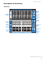
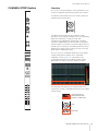
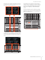
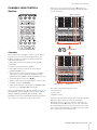
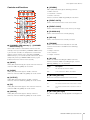
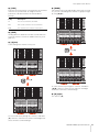
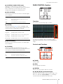
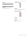
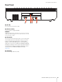
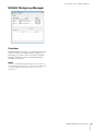
NUAGE FADER CONTROL SURFACE Ncs500-FD Operation Manual Using this manual This operation manual supports keyword searching and linking as follows. Keyword searching Searching for keywords is performed using your pdf viewer’s search function. If you are viewing this manual using Adobe Reader, type the term you wish to find into the Find toolbar and then press your computer’s [Enter] key. Jumping between pages If using Adobe Reader, you can jump forwards and backwards to various pages in this manual. This provides a convenient way to return to your original page after clicking a page link. EN Contents Introduction ..........................................................................................3 How to Read the Manual .................................................................................... 3 Description of the Device ....................................................................4 Top Panel ........................................................................................................... 4 Rear Panel ........................................................................................................ 22 Description of the Software Programs.............................................23 NUAGE FADER Setup ...................................................................................... 23 NUAGE Workgroup Manager........................................................................... 24 Troubleshooting (in operation).........................................................25 Appendix.............................................................................................25 Contents of the Getting Started Manual ........................................................... 25 Replacing Square-button Labels ..................................................................... 25 Pro Tools Control .............................................................................................. 26 Information • The illustrations and LCD screens as shown in this manual are for instructional purposes only, and may appear somewhat different from those on your device. • Windows is a registered trademark of Microsoft® Corporation in the United States and other countries. • Apple, Mac and Macintosh are trademarks of Apple Inc., registered in the U.S. and other countries. • The company names and product names in this manual are the trademarks or registered trademarks of their respective companies. NUAGE FADER Operation Manual 2 Introduction Introduction How to Read the Manual Types and Contents • Getting Started This is the manual included with the device. Read this manual when setting up the device. • Operation Manual This is the PDF manual downloaded from the website. Read this manual when needing information about the functions and how to use the device. Conventions • Brackets and quotation marks • Keyboard Shortcuts [Windows modifier key]/ [Mac modifier key] + [key] shows the shortcut keys. For example, [Ctrl]/ [command] + [Z] means “press [Ctrl] under Windows or [command] under Mac, then press [Z].” • Screens This manual predominantly uses screenshots of Windows. However, Mac screenshots are used when instructions of the function apply only to the Mac. Also, this manual uses screenshots of Nuendo 6. If you are using another version of Nuendo, the actual screenshots might not be the same. For details, refer to the Nuendo manuals (PDF) opened from the “Help” menu. Nuendo References For brevity, the descriptions of Nuendo functions in this manual have been kept simple and basic. For details on Nuendo functions, refer to the Nuendo manuals (PDF) opened from the “Help” menu. Brackets ([ ]) and quotation marks (“ ”) around names and phrases in this manual are used to indicate the following. Mark Indication target [] • Buttons, switches, indicators, terminals, etc. on the device. • Keys on a computer keyboard. ““ • Menus, buttons, tabs, areas, windows, etc. on a computer window or software window. • Excerpts of messages, function names, terms in the manual, etc. • Windows or Mac When the procedures or explanations are specific to only one of the platforms, Windows or Mac, this is properly indicated in the manual. When the platforms do not appear, procedures or explanations are for both Windows and Mac. • Procedures “” appears on some procedures in the manual. For example, the string “Devices” “Device Setup” “Control Panel” indicates that you should perform the procedures in the following order. 1. Click the “Devices” menu. 2. Select the “Device Setup” option. 3. Click the “Control Panel” button. NUAGE FADER Operation Manual 3 Description of the Device Description of the Device Top Panel SECTION CONTROL Section (page 14) CHANNEL STRIP Section (page 5) AUTOMATION Section (page 16) WORKSPACE Section (page 17) DAW SELECT Section (page 19) UNIT LINK Section (page 20) FLIP Section (page 20) MODIFIER Section (page 21) CONTROL ROOM Section (page 17) CHANNEL VIEW CONTROL Section (page 11) PAGE CONTROL Section (page 18) USER ASSIGNABLE Section (page 19) NUAGE FADER Operation Manual 4 Description of the Device CHANNEL STRIP Section Overview This section is for operating the channel parameters. The channel assignment automatically mirrors that of “Mixer.” The [Multi function knobs] are touch-sensitive knobs for adjusting various parameters. The [Multi function knob] has four separate control operations: touching (which brightens the corresponding parameter indication), turning, pressing, and simultaneously holding down and turning. The [Multi function A and B buttons] are directly below each [Multi function knob]. These buttons are for turning functions on and off or for selecting the controllable parameters of the [Multi function knobs]. Each channel has two sets of this knob and accompanying buttons. You can select the controllable parameters of the [Multi function knob] with the buttons in the “SECTION CONTROL Section” (page 14). Information on the controllable parameters of the [Multi function knob] is displayed in the Label Pane at the bottom of “Mixer.” The following chart indicates the relation between the “Label Pane” and the controllable parameters of the [Multi function knob]. Lit by touching knob Knob parameter value Functions on button A/B Knob Button A/B NUAGE FADER Operation Manual 5 Description of the Device Depending on which controllable parameters are selected in the SECTION CONTROL section, the [Multi function knob] has the following functions. Operation Function Touching • Highlights the parameter. • Shows the pop-up window. Turning • Adjusts the parameter. • Selects the parameter. • Moves the cursor. Pressing • Shows the pop-up window. • Sets the selected parameter. • Opens and closes the folder. The [e] buttons are used to activate Channel Setting mode in order to edit channels. In this mode, channel parameters can be controlled using the 32 [Multi function knobs]. Pressing one channel’s [e] button activates Channel Setting mode for that channel. Adjusts the parameter finely (fine mode). Simultaneously holding down and turning When you operate the [Multi function knob] while holding down the appropriate button(s) in the “MODIFIER Section” (page 21), the function changes as follows. Operation Function Simultaneously holding down [SHIFT] and turning knob Adjusts the parameter finely (fine mode). Simultaneously holding down [CTRL] and pressing knob Resets the parameter to the default value. In such a case, all 32 of the [Multi function knobs] can be used to adjust that channel’s parameters. NUAGE FADER Operation Manual 6 Description of the Device Alternatively, if the [e] buttons for two different channels are pressed at the same time, it will be possible to edit both of those channels simultaneously. If you again press the [e] button for a channel being edited, the “Mixer” will reappear. It should be noted that, even when Channel Setting mode is active, the specific parameters controlled by the individual [Multi function knobs] can be changed in the SECTION CONTROL section. The [Touch slider bar] is a touch controller for scrolling through the channels. When you slide your finger along the bar, the channels scroll across corresponding to the distance your finger travels. In such a case, 16 of the [Multi function knobs] can be used with each. Of the two channels, the one on the left can be controlled by the left bank of 16 knobs and viceversa. NUAGE FADER Operation Manual 7 Description of the Device Controls and Functions 1 [Multi function knob] Adjusts the various parameters. The color of the LED on the [Multi function knob] changes depending on the type of the controllable parameter. 2 1 2 Selects and turns on/off the controllable parameters of the [Multi function knobs]. 3 3 4 5 6 7 [Multi function button A]/[Multi function button B] [e] (edit) button The [e] (edit) button is used to activate Channel Setting mode in order to edit the channel in question. If the [e] buttons for two different channels are pressed at the same time, it will be possible to edit both of those channels simultaneously. If you again press the [e] button for a channel being edited, the “Mixer” will reappear. When you press [e] button while holding down the appropriate button(s) in the “MODIFIER Section” (page 21), the function changes as follows. Modifier button Function [SHIFT] When editing one channel, the display will switch to show two channels being edited. When editing two channels, the display will switch to show only the selected channel. 8 9 4 ) ! @ # Turns Read Automation on (lit) and off (dim). If you hold down one [R] button and press another, Read Automation between the two can be turned on and off. When you press [R] while holding down the appropriate button(s) in the “MODIFIER Section” (page 21), the function changes as follows. Modifier button Function [SHIFT] Turns Read Automation on for a number of successive channels. [ALT] Turns Read Automation on and off for all channels. 5 $ [R] [W] Turns Write Automation on (lit) and off (dim). If you hold down one [W] button and press another, Write Automation between the two can be turned on and off. When you press [W] while holding down the appropriate button(s) in the “MODIFIER Section” (page 21), the function changes as follows. Modifier button Function [SHIFT] Turns Write Automation on for a number of successive channels. [ALT] Turns Write Automation on and off for all channels. NUAGE FADER Operation Manual 8 Description of the Device 6 [MON] ) Turns Monitor on (lit) and off (dim). If you hold down one [MON] button and press another, Monitor between the two can be turned on and off. When you press [MON] while holding down the appropriate button(s) in the “MODIFIER Section” (page 21), the function changes as follows. Modifier button Function [SHIFT] Turns Monitor on for a number of successive channels. [ALT] Turns Monitor on and off for all channels. 7 When you press [REC] while holding down the appropriate button(s) in the “MODIFIER Section” (page 21), the function changes as follows. Modifier button Function [SHIFT] Turns Record Enable on for a number of successive channels. [ALT] Turns Record Enable on and off for all channels. Description Sliding Slide your finger along the bar at a slow speed. The channels scroll according to how far you slide. Flicking Quickly slide your finger along the bar and release it. Scrolling continues even after you release your finger, and then gradually comes to a stop. While the scrolling continues, you can stop it with your finger if desired. Bank flicking Slide your finger along the bar at a certain speed. The channels scroll in groups of eight. When you operate the [Touch slider bar] while holding down the appropriate button(s) in the “MODIFIER Section” (page 21), the function changes as follows. Modifier button Function [SHIFT] Holding this and flicking scrolls fully to either side. [CTRL] Holding this and sliding scrolls through the channels in groups of eight. [ALT] Holding this and touching sets the channel being edited in Channel Setting mode to the touched channel. If, however, the sequence of channels prevents scrolling to the touched channel, the display will scroll to the nearest one. [Channel name display] Displays the following channel information. Type Name ID Level meter The displayed icon of the channel type is the same as the icon on the track in Nuendo. The channel ID is marked with brackets ([ ]) when you move the channel to somewhere other than the Center area by using [ LOCK] (page 12) or [ LOCK] (page 12) in the CHANNEL VIEW CONTROL section. When you touch [Fader], the [Channel name display] will normally show the corresponding channel level. If, however, you are using FLIP (page 20), the value of the corresponding [Multi function knob] parameter will be displayed. To protect the displays and extend their operational life, the [Channel name displays] are darkened if the device is not operated for a certain period of time. You can configure this period of time from “OLED Off Time” (page 23) in NUAGE FADER Setup. 9 Operation [REC] Turns Record Enable on (lit) and off (dim). If you hold down one [REC] button and press another, Record Enable between the two can be turned on and off. 8 [Touch slider bar] Scrolls through the channels. The operating instructions are as follows. When you scroll through the channels by using the [Touch slider bar], you can have the [Faders] follow the scroll position. To turn this function on and off, select it from “Follow Slider Scroll” (page 23) in NUAGE FADER Setup. ! [SEL] Selects the channel. If you hold down one [SEL] button and press another, all channels between the two can be selected. When you press [SEL] while holding down the appropriate button(s) in the “MODIFIER Section” (page 21), the function changes as follows. Modifier button Function [SHIFT] For continuously selecting adjacent channels. [CTRL] For continuously selecting non-adjacent channels. [Channel color] Displays the channel color, to match the channel color of the track in Nuendo. NUAGE FADER Operation Manual 9 Description of the Device @ [SOLO] Turns Solo or Listen on (lit) and off (dim). If you hold down one [SOLO] button and press another, Solo or Listen between the two can be turned on and off. To select Solo or Listen, press [LISTEN] (page 18) in the CONTROL ROOM section. You can turn the motor power of the [Fader] on and off. To do this, select it from “Motor” (page 23) in NUAGE FADER Setup. When the motor power is off, you can change the [Fader] parameter after the [Fader] parameter value and the [Fader] position match. When you press [SOLO] while holding down the appropriate button(s) in the “MODIFIER Section” (page 21), the function changes as follows. Modifier button Function [SHIFT] Turns Solo or Listen on for a number of successive channels. [CTRL] Turns Solo or Listen on only of the channel for which you pressed [SOLO] last. [ALT] Turns Solo or Listen off for all channels. # [MUTE] Turns Mute on (lit) and off (dim). If you hold down one [MUTE] button and press another, Mute between the two can be turned on and off. When you press [MUTE] while holding down the appropriate button(s) in the “MODIFIER Section” (page 21), the function changes as follows. Modifier button Function [SHIFT] Turns Mute on for a number of successive channels. [ALT] Turns Mute off for all channels. $ [Fader] Adjusts the channel level. Each [Fader] is a touchsensitive 100 mm motorized fader. When you operate a [Fader] while holding down the appropriate button(s) in the “MODIFIER Section” (page 21), the function changes as follows. Modifier button Function [SHIFT] Adjusts the level finely (fine mode). [CTRL] Sets the nominal level. When you touch [Fader], the fader in “Mixer” will be highlighted. Also, you can select the channel by touching [Fader]. To turn this function on and off, select it from “Ch Select” (page 23) in NUAGE FADER Setup. When this function is on and you touch a [Fader] while holding down the [SHIFT] button in the “MODIFIER Section” (page 21), the function changes as follows. Modifier button Function [SHIFT] Continuously selects adjacent channels. NUAGE FADER Operation Manual 10 Description of the Device CHANNEL VIEW CONTROL Section When you select a channel then press [ LOCK], the selected channel will be moved to the left and entered to the Left Lock area. Select a channel Center area Press [ LOCK] Overview This section is for selecting the channel view of “Mixer.” Overall, this section has the following functions. The buttons used for selecting the respective modes are indicated in parentheses. • Hides and shows the selected channels. ([HIDE]/ [ALL CH]) • Links the selected channels. ([LINK]) • Hides and shows the channels by selected type. ([INPUT], [AUDIO], etc.) • Shows only the channels which match the condition under which you press the button (Agent function). ([EVENT ON TR], [EVENT CYCLE], [PLAYING CH], etc.) • Scrolls through the channels. ([]/[]) • Shows channels which are related to the channel, such as Group channels. ([EXPAND]) Left Lock area Center area • Stores and recalls the channel view. ([CHANNEL VIEW memory 1] – [CHANNEL VIEW memory 4]) The “Mixer” has the following three areas. When you simultaneously hold down [CTRL] (page 21) in the MODIFIER section and press any one of the buttons [INPUT], [AUDIO], [OUTPUT], [FX], [GROUP], and [OTHERS], which are for hiding and showing channels by type, only the channel type you pressed is shown. • Left Lock area • Center area • Right Lock area Channels moved to the Left Lock area cannot be scrolled through. In other words, the channels are always displayed. When you select a channel in the Left Lock area and then press [ LOCK], the selected channel will be moved back to the Center area. Channels in the Center area can be scrolled through. The Right Lock area is used in the same way as the Left Lock area. NUAGE FADER Operation Manual 11 Description of the Device Controls and Functions 7 [OTHERS] Hides (dim) and shows (lit) the following channels. • “MIDI” channels 1 3 2 5 4 • “Instrument” channels • “Rewire” channels However, channels hidden by [HIDE] are not shown. 6 8 7 Shows channels which have events on the track. 9 8 ) 9 [EVENT ON TR] [EVENT CYCLE] Shows channels which have events in the Cycle range. @ ! # $ ^ & % ( * A ) Shows channels which are currently playing. ! [CHANNEL VIEW memory 1] – [CHANNEL VIEW memory 4] Stores and recalls the current Mixer channel view. For example, when you hold down [CHANNEL VIEW memory 1] for over two seconds, the lamp flashes several times and the current channel view is stored to [CHANNEL VIEW memory 1]. To recall the stored channel view, press and quickly release [CHANNEL VIEW memory 1] (the button to which the channel view is stored). 2 [INPUT] Hides (dim) and shows (lit) the “Input” channels. However, channels hidden by [HIDE] are not shown. 3 [AUDIO] Hides (dim) and shows (lit) the “Audio” channels. However, channels hidden by [HIDE] are not be shown. [OUTPUT] Hides (dim) and shows (lit) the “Output” channels. However, channels hidden by [HIDE] are not be shown. 5 [FX] Hides (dim) and shows (lit) the “FX” channels. However, channels hidden by [HIDE] are not be shown. 6 [GROUP] Hides (dim) and shows (lit) the “Group” channels. However, channels hidden by [HIDE] are not be shown. [EXPAND] Shows channels which are related to the selected channel. This function is available for the following channels. • “Group” channels • “FX” channels • “Output” channels # [ALL CH] Shows all channels including the hidden channels. However, channels hidden according to type, such as [INPUT], [AUDIO], etc., are not shown. Lamp Description Lit All channels are shown in “Mixer.” Dim Some channels in “Mixer” are hidden. $ 4 [SEL CH] Shows channels which are currently selected. @ 1 [PLAYING CH] [ LOCK] (lock left) Moves the selected channels to the Left Lock area. Lamp Description Lit The selected channels are in the Left Lock area. Dim The selected channels are not in the Left Lock area. % [ LOCK] (lock right) The same as [ LOCK], except applied to the Right Lock area. NUAGE FADER Operation Manual 12 Description of the Device ^ [LINK] ( Links the selected channels. The parameters of the linked channels are synchronized. To configure the Link parameters, edit them from the relevant window in Nuendo. Lamp Description Lit The selected channels are linked. Dim Link can be set for the selected channels. Dark The channels have not been selected yet. & [BANK] Turns bank scroll on (lit) and off (dim). When this is turned on, you can scroll through the channels in groups of eight by using []/[]. [HIDE] Holding down this button for over 0.3 seconds hides the selected channels. To show the hidden channels, press [ALL CH]. * [] (left) 9 Scrolls through the channels one by one. 16 17 24 Press []. 9 16 17 24 Press []. 1 8 9 16 To scroll continuously through the channels, hold down []/[]. However, channels in the Left Lock and Right Lock areas cannot be scrolled through. A [] (right) The same as []. 8 15 16 23 To scroll continuously through the channels, hold down []. However, channels in the Left Lock and Right Lock areas cannot be scrolled through. NUAGE FADER Operation Manual 13 Description of the Device SECTION CONTROL Section When you press [EQ] again, the “Section” view and the controllable parameters of the [Multi function knobs] revert back to the default (meaning that none of the buttons such as [QUICK CTRL] and [PRE] are turned on). The same applies when Channel Setting mode is active for the CHANNEL STRIP section in question. Depending on which controllable parameters are selected in the SECTION CONTROL section, the [Multi function knob] has the following functions. Operation Function Touching • Highlights the parameter. • Shows the pop-up window. Turning • Adjusts the parameter. • Selects the parameter. • Moves the cursor. Pressing • Shows the pop-up window. • Sets the selected parameter. • Opens and closes the folder. Simultaneously holding down and turning Adjusts the parameter finely (fine mode). Overview This section is for operating the “Section” view of “Mixer” and selecting the controllable parameters of the [Multi function knobs] (page 8) in the CHANNEL STRIP section. When you operate the [Multi function knob] while holding down the appropriate button(s) in the “MODIFIER Section” (page 21), the function changes as follows. Operation Function Adjusts the parameter finely (fine mode). Simultaneously holding down [SHIFT] and turning knob Simultaneously holding down [CTRL] and pressing knob The buttons [QUICK CTRL], [PRE], [ROUTING], [PAN], [SENDS], [CUES], [INSERT], [DYN], and [EQ] are for selecting the “Section” view and the controllable parameters of the [Multi function knobs]. For example, when you press [EQ], the “Section” view changes to the “EQ” view and the controllable parameters of the [Multi function knobs] change to “EQ.” Resets the parameter to the default value. The buttons [Sub parameter 1] – [Sub parameter 8] and []/[] are for selecting the parameter type or slot of the controllable parameters of the [Multi function knobs]. NUAGE FADER Operation Manual 14 Description of the Device Controls and Functions 5 [QUICK CTRL] Changes the “Section” view to “QUICK.” The controllable parameters of the [Multi function knobs] (page 8) in the CHANNEL STRIP section change to “Quick Controls.” 3 When the CHANNEL STRIP section is in the Channel Settings mode, you can assign and lock parameters to the [Multi function knobs]. To do this: 4 1. Move the mouse cursor to the desired 1 2 5 6 parameter to be assigned. 7 The parameter is temporary assigned to the [Multi function knob] which is not parameter-locked. 9 8 NOTE ) Only automatable parameters can be assigned. @ ! # 2. Press [Multi function button B] of the [Multi function knob] for which you want to lock the parameter for Quick Control. 1 [Sub parameter 1] – [Sub parameter 8] The parameter is locked. To unlock the parameter, press [Multi function button B] again. Selects the parameter type or slot of the controllable parameters of the [Multi function knobs] (page 8) in the CHANNEL STRIP section. Lamp Description Lit The parameter type or slot has been selected. Dim The parameter type or slot can be selected. Dark The parameter type or slot cannot be selected. 2 [METER] Selects the meter view in “Section.” Lamp Description Lit The meter view is set to Graph (conventional). Dim The meter view is set to Wave (waveforms of audio events). 3 [] (down) Selects the parameter type or slot of the controllable parameters of the [Multi function knobs] (page 8) in the CHANNEL STRIP section one by one. The button lights when held down. Lamp Description Dim The parameter type or slot can be selected. Dark The parameter type or slot cannot be selected. 4 [] (up) The same as []. 6 [PRE] Changes the “Section” view to “PRE.” The controllable parameters of the [Multi function knobs] (page 8) in the CHANNEL STRIP section change to “FILTER.” 7 [ROUTING] Changes the “Section” view to “ROUTING.” The controllable parameters of the [Multi function knobs] (page 8) in the CHANNEL STRIP section change to “Direct Routings.” When you press the [Multi function knob], the pop-up window for selecting the Direct Routings is shown. You can select the parameter by turning the [Multi function knob], and set the parameter by pressing the [Multi function knob]. 8 [PAN] Changes the “Section” view to “PAN.” The controllable parameters of the [Multi function knobs] (page 8) in the CHANNEL STRIP section change to “Pan.” 9 [SENDS] Changes the “Section” view to “SENDS.” The controllable parameters of the [Multi function knobs] (page 8) in the CHANNEL STRIP section change to “Sends.” When you press the [Multi function knob], the pop-up window for selecting the routings of “Sends” is shown. You can select the parameter by turning the [Multi function knob], and set the parameter by pressing the [Multi function knob]. NUAGE FADER Operation Manual 15 Description of the Device ) [CUES] AUTOMATION Section Changes the “Section” view to “CUES.” The controllable parameters of the [Multi function knobs] (page 8) in the CHANNEL STRIP section change to “Cues.” ! [INSERT] Changes the “Section” view to “INSERTS.” The controllable parameters of the [Multi function knobs] (page 8) in the CHANNEL STRIP section change to “Inserts.” When you press the [Multi function knob], the pop-up window for selecting the plug-ins of “Inserts” is shown. You can select the parameter by turning the [Multi function knob], and set it by pressing the knob. When the plug-in effect window is displayed in “Section,” you can assign and lock the parameter in the plug-in effect to the [Multi function knob]. To do this: 1. Move the mouse cursor to the desired parameter to be assigned. The parameter is temporary assigned to the [Multi function knob] which is not parameter-locked. 2. Press [Multi function button B] of the [Multi function knob] for which you want to lock the parameter. The parameter is locked. To unlock the parameter, press [Multi function button B] again. To close the plug-in effect window, press [INSERT]. @ [DYN] Changes the “Section” view to “STRIP.” The controllable parameters of the [Multi function knobs] (page 8) in the CHANNEL STRIP section change to “Strip.” # Overview This section is for operating the Automation functions. Controls and Functions 1 1 2 3 4 [ON] Turns all Suspend Read and Suspend Write options on and off. Activates and deactivates Read Automation and Write Automation for all channels. Lamp Description Lit All Suspend Read and Suspend Write options are disabled. Dim One or more Suspend Read or Suspend Write options are enabled. 2 [LATCH] Sets Automation Mode to “Auto-Latch” (lit) or another mode (dim). 3 [PREVIEW] Turns “Preview” on (lit) and off (dim). When this is on, you can operate the “Preview” function. [EQ] Changes the “Section” view to “EQ.” The controllable parameters of the [Multi function knobs] (page 8) in the CHANNEL STRIP section change to “EQ.” 4 [PUNCH] Used to activate the “Punch” function. NUAGE FADER Operation Manual 16 Description of the Device WORKSPACE Section CONTROL ROOM Section Overview This section is for recalling Workspaces. To create and lock Workspaces, edit them in Nuendo. Controls and Functions 1 1 [WORKSPACE 1] – [WORKSPACE 4] Recalls “Workspace 1” – “Workspace 4.” The button lights when held down. You can recall up to four Workspaces. Overview This section is for operating the Control Room functions. To use this section, make sure that Control Room is set to on in Nuendo and that the channels you need have been created, then configure the input/output routings for those channels. The [CONTROL ROOM LEVEL knob] is for adjusting the Control Room level. However, when [PHONES] is on, you can adjust the Phones level by this knob. If you have configured multiple DAW software programs and operate them by selecting the DAW SELECT Section (page 19), the [DOWN MIX], [DIM], [CONTROL ROOM LEVEL knob] and [PHONES] controls will always be applied to the Control Room of DAW A. In other words, this section is not affected by the DAW software selection. Controls and Functions 1 3 2 4 1 5 6 7 [DOWN MIX] Selects the Downmix presets one by one. Lamp Description Lit A Downmix preset other than the first has been selected. Dim The first Downmix preset has been selected. 2 [DIM] Turns Dim on (lit) and off (dim). When this is on, the Control Room audio level is lowered. When this is off, the previous level is restored. You can set the Dim level on Nuendo. NUAGE FADER Operation Manual 17 Description of the Device 3 [CONTROL ROOM LEVEL knob] PAGE CONTROL Section Adjusts the Control Room level. However, when [PHONES] is on, you can adjust the Phones level with this knob. To adjust the level more finely (fine mode), simultaneously hold down the knob and turn it. 4 [SOLO CLEAR] Turns off Solo or Listen for all channels. The button lights when held down. Lamp Description Flash One or more channels in Mixer have Solo or Listen turned on. Dark Solo and Listen are off for all channels. 5 Overview This section is for operating “Page” in “Mixer.” [LISTEN] Sets the function of (page 10) in the CHANNEL STRIP section to Solo or Listen. To select AFL and PFL of Listen, select them in the Control Room on Nuendo. Lamp Description Lit (green) [SOLO] operates as Listen of PFL. Dim (green) [SOLO] operates as Solo. Listen setting is PFL. Lit (orange) [SOLO] operates as Listen of AFL. Dim (orange) [SOLO] operates as Solo. Listen setting is AFL. 6 [METER RESET] Resets the meter view for all channels. The button lights when held down. 7 The page which displays “Mixer” information and the page which operates the channel view are displayed on “Page.” Controls and Functions [PHONES] Sets the [CONTROL ROOM LEVEL knob] to control Phones. When you turn this on, you can adjust the Phones level with the [CONTROL ROOM LEVEL knob]. Lamp Description Lit The knob controls the Phones level. Dim The knob controls the Control Room level. 2 1 3 4 1 [PAGE] Selects “Page.” 2 [ESC] For closing a pop-up window. 3 [ENTER] Executes the selected item and turns it on/off. 4 []/[]/[]/[] (up/left/down/right) Moves the cursor on “Page” and selects the “Page” view. When you hold down []/[]/[]/[], the cursor/page selection will be moved/selected continuously. NUAGE FADER Operation Manual 18 Description of the Device USER ASSIGNABLE Section DAW SELECT Section Overview This section is used to execute assigned functions. To assign the desired function, edit it from “User Assignable Settings” (page 23) in NUAGE FADER Setup. Controls and Functions 1 1 [F1] – [F3] Executes the assigned function. The button lights when held down. Lamp Description Dim The function has been assigned. Dark The function has not been assigned yet. Overview This section is for selecting the target DAW software for operation. This section allows you to select the particular DAW software when you have connected and configured multiple DAW software programs. For details on connecting and settings, refer to the NUAGE Workgroup Manager manual (page 24; PDF). Controls and Functions 1 2 1 [DAW A] – [DAW C] Selects the target DAW software for operation. Lamp Description Lit The DAW software has been selected. Dim The DAW software has not been selected yet. Dark The DAW software has not been configured yet. 2 [MAIN DISP] Shows the Project Window in the secondary Mixer display, as well as the main Nuage Master display. In order to use this function, a KVM switch must be set up and the data to be sent to the switch must be configured using NUAGE Workgroup Manager. NUAGE FADER Operation Manual 19 Description of the Device UNIT LINK Section FLIP Section Overview This section is for turning on and off UNIT LINK. When you connect multiple Nuage Fader units (up to a maximum of three) and turn on UNIT LINK, the connected Nuage Fader units operate in synchronization. When you turn off UNIT LINK, the unit operates independently. Controls and Functions 1 1 [UNIT LINK] Overview This section is for operating the FLIP function. Turning on FLIP [KNOB 1] or [KNOB 2] lets you use the [Fader] (page 10) in the CHANNEL STRIP section to control the parameters assigned to the [Multi function knobs] (page 8). [KNOB 1] represents the upper sixteen [Multi function knobs], and [KNOB 2] represents the lower sixteen [Multi function knobs]. When pressing [KNOB 1] Turns UNIT LINK on (lit) and off (dim). It should be noted that certain parameters assignable to [Multi function knobs] cannot be controlled using the [Faders]. Controls and Functions 1 2 NUAGE FADER Operation Manual 20 Description of the Device 1 [KNOB 1] MODIFIER Section Allows you to operate the controllable parameters of the upper sixteen [Multi function knobs] with the [Faders]. Lamp Description Lit FLIP is on. Dim FLIP is off. 2 [KNOB 2] The same as [KNOB 1]. However, this button is for the lower sixteen [Multi function knobs]. Overview This section is for the modifier buttons. The buttons operate the same as [Shift], [Ctrl]/[Command], and [Alt]/ [Option] on the computer keyboard. Controls and Functions 1 2 3 1 [SHIFT] Operates the Shift function. 2 [CTRL] Operates the Ctrl/Command function. 3 [ALT] Operates the Alt/Option function. NUAGE FADER Operation Manual 21 Description of the Device Rear Panel 1 1 2 3 4 [AC IN] For connection to the power cable. 2 [Power switch] Turns the power on (|) and off (P). NOTICE Rapidly turning the unit on and off in succession can cause it to malfunction. After turning the unit off, wait for at least 6 seconds before turning it on again. 3 [RS-232C] For connection to an RS-232C cable. Connect this port to the RS-232C port on the KVM switch. When you switch between multiple DAW applications using the DAW SELECT section with KVM switches connected and the data to be sent to them configured in NUAGE Workgroup Manager, the display content, active keyboard, and active mouse will also change accordingly. For details, refer to the PDF manual of NUAGE Workgroup Manager (page 24). 4 [Network] For connecting an Ethernet cable. NUAGE FADER Operation Manual 22 Description of the Software Programs Description of the Software Programs 3 Fader Adjusts the touch sensitivity of the [Fader]. The larger the number, the higher the sensitivity. 4 NUAGE FADER Setup LED Low Adjusts the brightness of the LED (when dimmed). The larger the value, the brighter the LED. 5 LED High Adjusts the brightness of the LED (when fully lit). The larger the value, the brighter the LED. 6 OLED Adjusts the brightness of the [Channel name display]. The larger the value, the brighter the LED. 7 Follow Slider Scroll Turns on and off the function which causes the [Fader] position to follow scrolling through the channels when you use the [Touch slider bar]. When this function is off, the [Fader] position changes only after you stop scrolling. Overview 8 This software is for configuring the general settings of Nuage Fader from Nuendo. You can configure settings such as touch sensitivity or LED brightness. To open this window, click the Nuendo menu “Devices” “NUAGE FADER Setup.” 9 When multiple Nuage Fader units are connected, the settings are the same on all Nuage Fader units. 3 4 5 6 ! 9 ) 7 8 OLED Off Time Configures the period of time that elapses before the [Channel name display] is automatically darkened. Controls and Functions 2 Ch Select Turns on and off the function which allows you to select channels by touching [Fader]. ) 1 Motor Turns the motor power of [Fader] on and off. When the motor power is off, you can change the [Fader] parameter after the [Fader] parameter value and the [Fader] position match. User Assignable Settings Assigns the function to the buttons in “USER ASSIGNABLE section” (page 19). First, click “Category” to select the category. Next, click “Command” to select the command. When you check a box in “Repeat,” the function will operate continuously when the button is held down. ! 1 Knob Adjusts the touch sensitivity of the [Multi function knob]. The larger the number, the higher the sensitivity. 2 Slider Adjusts the touch sensitivity of the [Touch slider bar]. The larger the number, the higher the sensitivity. NUAGE FADER Operation Manual 23 Description of the Software Programs NUAGE Workgroup Manager Overview NUAGE Workgroup Manager is an application that allows control over devices and DAW software programs as a Workgroup on a Nuage system. For details on NUAGE Workgroup Manager, refer to the NUAGE Workgroup Manager manual (PDF). NOTE To open the NUAGE Workgroup Manager manual, double-click the NUAGE Workgroup Manager icon on the task tray (Windows) or menu bar (Mac) for opening the window, then click the “Manual” icon. NUAGE FADER Operation Manual 24 Troubleshooting (in operation) Troubleshooting (in operation) Appendix Contents of the Getting Started Manual A connection cannot be established with Pro Tools. • Ensure that the steps described in “Settings for Pro Tools” (page 26) have been completed. PRECAUTIONS NOTICE Information Introduction A Message from the Development Team The [Fader] motors do not operate. • Ensure that the [Fader] motors are turned on. To do so, check the settings from “Motor” (page 23) in NUAGE FADER Setup. Included Accessories Items to Have Ready How to Read the Manual Setup Overall Process Setting and Connecting The [Channel name displays] turn off unexpectedly. • The [Channel name displays] turn off automatically after a certain period of inactivity in order to protect them. You can set this period using “OLED Off Time” (page 23) in NUAGE FADER Setup. Setting up the Power Supply Installing TOOLS for NUAGE Configuring the Workgroup on NUAGE Troubleshooting (in setting up) Appendix Contents of the Operation Manual Firmware Updates [REC] from the CHANNEL STRIP section cannot be turned on. • “Input Routing” must be set in order to turn on [REC] for “Audio” channels. Adjusting the Touch Sensitivity Specifying the Brightness Calibrating Fader Motion or Position Resetting to the Factory Default Condition Dimensions Specifications The [Faders] do not move in response to channel scrolling using the [Touch slider bar]. • The function allowing the [Faders] to reflect [Touch slider bar] actions is turned off. Turn on “Follow Slider Scroll” (page 23) in NUAGE FADER Setup. Replacing Square-button Labels The labels from the square buttons can easily be replaced. These replacements can be made by cutting a transparent or semi-transparent sheet into 10 x 10 mm pieces. To install, simply remove the button’s cap, swap out the current label, and replace the cap. NUAGE FADER Operation Manual 25 Appendix Pro Tools Control Setting Pro Tools MIDI Controllers 1. Start up Pro Tools. Introduction In addition to Nuendo and Cubase, Nuage Fader and Nuage Master devices can also be used to control Pro Tools (Mac only; basic functions only). 2. Choose “Setup” “Peripherals” to open the “Peripherals” dialog. 3. Click the “MIDI Controllers” tab. 4. Set the parameters on the “MIDI NOTE Controllers” window as shown below. • When working with Pro Tools, up to two Nuage Faders together with an optional Nuage Master can be connected. • Nuendo must also be used in order to control Pro Tools. In addition, Nuendo must be set as the main DAW (i.e., DAW A) using NUAGE Workgroup Manager. The following sections will describe the connections and settings that must be made in order to control Pro Tools, in addition to the functions of the various buttons. For the purpose of these descriptions, it is assumed that the Nuage Fader and Nuage Master devices and Nuendo have already been fully set up. Only “#1” should be set for the following configuration: • One Nuage Master only “#1” and “#2” should be set for the following configurations: • One Nuage Fader only Making Connections • One Nuage Fader and one Nuage Master Connect the Mac computer running Pro Tools to the network containing the Nuage Fader and Nuage Master devices to be used. “#1” through “#4” should be set for the following configurations: NOTE • Two Nuage Faders and one Nuage Master • Two Nuage Faders If the Mac computer in question is equipped with multiple Ethernet ports, use the first one to connect to the network. Adding to NUAGE Workgroup Manager Settings Installing NUAGE PT Bridge NUAGE PT Bridge is an application that makes it possible to control Pro Tools (Mac only) using Nuage Fader and Nuage Master devices. This application should be installed on the Mac running Pro Tools. It can be selected for installation as part of the TOOLS for NUAGE package. If necessary, download TOOLS for NUAGE from the following web site and use it to install NUAGE PT Bridge. When MIDI ports have been set correctly as described above, Pro Tools will appear in NUAGE Workgroup Manager. Add Pro Tools to the same Workgroup as Nuendo. This completes the setup procedure for controlling Pro Tools. The buttons in the DAW SELECT section of the Nuage Fader and Nuage Master devices can be used to select the DAW application to be controlled. The following section describes the functions performed by Nuage Fader buttons when controlling Pro Tools. http://www.yamahaproaudio.com/downloads/ NUAGE FADER Operation Manual 26 Appendix Button Functions CHANNEL STRIP Section [Fader] The faders are used to set channel levels, or to set send levels in Flip mode. CHANNEL VIEW CONTROL Section [CHANNEL VIEW memory Not applicable. 1] – [CHANNEL VIEW memory 4] [INPUT] [AUDIO] [Touch slider bar] Slide to scroll the channels. [OUTPUT] [Channel color] Not applicable. [FX] [Channel name display] This area displays the channel strip name, the Automation mode, the send channel, and other related information. [GROUP] [SOLO] This button is used to solo channels. [EVENT CYCLE] [MUTE] This button is used to mute channels. [OTHERS] [EVENT ON TR] [PLAYING CH] [SEL] This button is used to select channels. [MON] Not applicable. [REC] This button is used to arm Pro Tools channels for recording. The button indicators of channels that are armed flash. The button indicators of armed channels light continuously when recording starts. [W] [e] (edit) [ LOCK] (lock right) [LINK] [HIDE] [SEL CH] [EXPAND] [ALL CH] [] (left) This key is used to scroll to the left one channel at a time. If pressed when [BANK] is on, the channels will be scrolled one bank at a time. [BANK] If the [] or [] key is pressed when this key is on (lit), the channels will be scrolled one bank at a time to the left or right. [] (right) This key is used to scroll to the right one channel at a time. If pressed when [BANK] is on, the channels will be scrolled one bank at a time. This button is used to cycle through Touch, Latch, Write, and Off Automation modes. The lighting pattern of the [W] and [R] buttons indicates various Automation mode states as follows. Automation mode [R] [W] Off Off Off Read On Off Touch, Latch, or Write Off Flashing (standby) /On (writing) Trim + Read On Flashing Trim + Touch, Latch, Flashing (standby) On or Write /On (writing) [R] [ LOCK] (lock left) This button is used to turn Automation Read mode on and off. Refer to the description of the [W] button for details regarding its lighting pattern. Not applicable. [Multi function knob] (upper) SECTION CONTROL Section [METER] Not applicable. [] (down) [] (up) [QUICK CTRL] [PRE] [Multi function button A]/ [Multi function button B] (upper) [ROUTING] [Multi function knob] (lower) This knob is used to set the pan or send level. [Multi function button A]/ [Multi function button B] (lower) Not applicable. [PAN] When this button is pressed, the Encoders work as channel panpots. Its indicator lights up when it’s pressed. [SENDS] When this button is pressed, the Encoders work as send level controls. Its indicator lights up when it’s pressed, and send A is selected automatically. NUAGE FADER Operation Manual 27 Appendix [CUES] Not applicable. PAGE CONTROL Section [INSERT] [PAGE] [DYN] [ESC] [EQ] [ENTER] [Sub parameter 1] [Sub parameter 2] [Sub parameter 3] These buttons are used to select sends A – E. The button indicator of the currently selected send lights up. [Sub parameter 4] []/[]/[]/[] (up/left/down/right) USER ASSIGNABLE Section [Sub parameter 5] [Sub parameter 6] Not applicable. [F1] – [F3] Not applicable. Not applicable. [Sub parameter 7] DAW SELECT Section [Sub parameter 8] [DAW A] – [DAW C] AUTOMATION Section [ON] [MAIN DISP] These buttons perform the same tasks as when working with Nuendo. Not applicable. [LATCH] UNIT LINK Section [PREVIEW] [UNIT LINK] [PUNCH] WORKSPACE Section [WORKSPACE 1] This button is used to make the Mix window the active window. [WORKSPACE 2] This button is used to make the Edit window the active window. [WORKSPACE 3] This button is used to open and close the Transport window. Its indicator lights up while the Transport window is open. [WORKSPACE 4] Not applicable. Not applicable. FLIP Section [KNOB 1] This knob switches Pro Tools to Flip mode. When in this mode, the knob’s LED will be lit. [KNOB 2] This button is used in conjunction with other buttons to modify function operation. This corresponds to the Option modifier key found on Mac keyboards. MODIFIER Section CONTROL ROOM Section [DOWNMIX] [DIM] [CONTROL ROOM LEVEL knob] [SHIFT] This button is used in conjunction with other buttons to modify function operation. This corresponds to the Shift modifier key found on Mac keyboards. [CTRL] This button is used in conjunction with other buttons to modify function operation. This corresponds to the Control modifier key found on Mac keyboards. [ALT] This button is used in conjunction with other buttons to modify function operation. This corresponds to the Command modifier key found on Mac keyboards. These controllers are used to operate the DAW A Nuendo.*1 [SOLO CLEAR] [LISTEN] [METER RESET] [PHONES] *1: Control Room functions normally control Nuendo as the main DAW (i.e., DAW A). In order, therefore, to output Pro Tools audio signals from the Nuage system, the Pro Tools audio interface’s outputs must be connected to the Nuage system audio interface’s inputs, and the appropriate input and output settings must be made on Nuendo’s VST Connections window (selected from the Devices menu). NUAGE FADER Operation Manual 28 Yamaha Pro Audio Global Web Site http://www.yamahaproaudio.com/ Yamaha Manual Library http://www.yamaha.co.jp/manual/ C.S.G., Pro Audio Division © 2013 Yamaha Corporation 302MW-A1