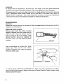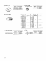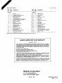
1
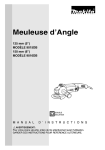
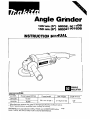
Angle Grinder
125 mm (5”) MODEL 9015DB
150 mm (6”) MODEL 9016DB
DOUBLE
INSULATION
MODEL
No load speed (RPM)
9015DB
10,000
9016DB
9,000
Overall length
Net weight
391 mm (15-318”)
2 4 kg (5 3 Ibs)
WARNING: For your personal safety, READ and UNDERSTAND before using
SAVE THESE INSTRUCTIONS FOR FUTURE REFERENCE.
Spindle thread
518
“
1
GENERAL SAFETY RULES
(For All Tools)
WARNING! Read and understand all instructions. Failure
to follow all instructions listed below, may result in electric
shock, fire and/or serious personal injury.
SAVE THESE INSTRUCTIONS
READ ALL INSTRUCTIONS.
Work Area
1. Keep your work area clean and well lit. Cluttered benches and dark areas invite
accidents.
2. Do not operate power tools in explosive atmospheres, such as in the presence
of flammable liquids, gases, or dust. Power tools create sparks which may
ignite the dust or fumes.
3. Keep bystanders, children, and visitors away while operating a power tool.
Distractionscan cause you to loose control.
Electrical Safety
4. Double Insulated tools are equipped with a polarized plug (one blade is wider
than the other.) This plug will fit in a polarized outlet only one way. If the
plug does not fit fully in the outlet, reverse the plug. If it still does n o t fit,
contact a qualified electrician t o install a polarized outlet. Do not change
eliminates the need for the three wire
the plug in any way. Double insulation
grounded power cord and grounded power supply system.
5. Avoid body contact with grounded surfaces such as pipes, radiators, ranges
and refrigerators. There is an increased risk of electric shock if your body is
grounded.
6. Don't expose power tools t o rain or wet conditions. Water entering a power
tool will increase the risk of electric shock.
7. Do not abuse t h e cord. Never use the cord t o carry the tools or pull the plug
from an outlet. Keep cord away from heat, oil, sharp edges or moving parts.
Replace damaged cords immediately. Damaged cords increase the risk of electric
shock.
8. When operating a power tool outside, use an outdoor extension cord marked
"W-A" or "W." These cords are rated for outdoor use and reduce the risk of
electric shock.
Personal Safety
9. Stay alert, watch what you are doing and use common sense when operating
a power tool. Do not use tool while tired or under the influence of drugs,
alcohol, or medication. A moment of inattention while operating power tools
may result in serious personal injury.
10. Dress properly. Do n o t wear loose clothing or jewelry. Contain long hair. Keep
your hair, clothing, and gloves away from moving parts. Loose clothes, jewelry
or long hair can be caught in moving parts.
11. Avoid accidental starting. Be sure switch is off before plugging in. Carrying
tools with your finger on the switch or plugging in tools that have the switch
on invites accidents.
12. Remove adjusting keys or switches before turning the t o o l on. A wrench or
a key that is left attached to a rotating part of the tool may result in personal injury.
13. Do not overreach. Keep proper footing and balance a t all times. Proper footing
and balance enables better control of the tool in unexpected situations.
14. Use safety equipment. Always wear eye protection. Dust mask, non-skid
safety shoes, hard hat, or hearing protection must be used for appropriate conditions.
Tool Use and Care
15. Use clamps or other practical way t o secure and support the workpiece t o
a stable platform. Holding the work by hand or against your body is unstable
and may lead to loss of control.
16. Do n o t force tool. Use the correct tool for your application. The correct tool
will do the job better and safer at the rate for which it is designed.
17. Do n o t use t o o l if switch does not turn it o n or off. Any tool that cannot be
controlled with the switch is dangerous and must be repaired.
18. Disconnect t h e plug from the power source before making any adjustments,
changing accessories, or storing the tool. Such preventive safety measures
reduce the risk of starting the tool accidentally.
19. Store idle tools out of reach of children and other untrained persons. Tools
are dangerous in the hands of untrained users.
20. Maintain tools with care. Keep cutting tools sharp and clean. Properly
maintained tools, with sharp cutting edges are less likely to bind and are easier
to control.
21. Check for misalignment or binding of moving parts, breakage of parts, and
any other condition that may affect the tools operation. If damaged, have
the t o o l service before using. Many accidents are caused by poorly maintained
tools.
22. Use only accessories that are recommended by t h e manufacturer for your
model. Accessories that may be suitable for one tool, may become hazardous
when used on another tool.
Service
23.Tool service must be performed only b y qualified repair personnel. Service
or maintenance performed by unqualified personnel could result in a risk of
injury.
24. When servicing a tool, use only identical replacement parts. Follow instructions in the Maintenance section of this manual. Use of unauthorized parts
or failure to follow Maintenance Instructions may create a risk of electric shock
of injury.
3
Specific Safety Rules
1. Always use proper guard with grinding wheel. A guard protects operator from
broken wheel fragments
2. Accessories must be rated for at least the speed recommended on the tool
warning label. Wheels and other accessories running over rated speed can
fly apart and cause injury.
3. Hold tool by insulated gripping surfaces when performing an operation where
the cutting tool may contact hidden wiring or its o w n cord. Contact with
a "live" wire will make exposed metal parts of the tool "live" and shock the
operator.
4. Keep guards in place.
5. Use only wheels having a maximum operating speed at least as high as "No
Load RPM" marked on the tool's nameplate. When using depressed center
wheels, be sure t o use only fiberglass-reinforced wheels.
6. Check the wheel carefully for cracks or damage before operation. Replace
cracked or damaged wheel immediately.
7. Use only flanges specified for this tool.
8. Be careful not t o damage the spindle, t h e flange (especially t h e installing
surface) or the lock nut. Damage t o these parts could result in wheel breakage.
9. Hold the tool firmly.
I O . Keep hands away from rotating parts.
11. Make sure the wheel is not contacting the workpiece before the switch is
turned on.
12. Before using the tool on an actual workpiece, let it run for a while. Watch
for vibration or wobbling that could indicate poor installation or a poorly
balanced wheel.
13. Use the specified surface of the wheel t o perform the grinding.
14. Watch out for flying sparks. Hold the tool so that sparks fly away from you
and other persons or flammable materials.
15. Do not leave t h e tool running. Operate the tool only when hand-held.
16. Do not touch the workpiece immediately after operation; it may be extremely
hot and could burn your skin.
SAVE THESE INSTRUCTIONS.
4
The followings show the symbols used for tool
v
.................................
A
.................................
volts
amperes
HZ
.................................
herts
kg
kilograms
hours
S
.................................
.................................
.................................
.................................
seconds
?J
.................................
alternating current
h
min
minutes
--__
- .................................
direct current
n,
.................................
no load speed
.................................
alternating or direct current
__
’
Class II Construction
A
.................................
splash-proof construction
AA
.................................
watertight construction
.../min
................................
revolutions or reciprocation per minute
e
.................................
number of blow
5
Installing wheel guard
CAUTION:
Always be sure that the tool is switched off
and unplugged before installing or removing the wheel guard.
Mount the wheel guard with the tab on the
wheel guard band aligned with the notch
on the bearing box. Then rotate the wheel
guard 180 degrees counterclockwise. Be
sure to tighten the screw securely.
Installingside grip (auxiliary handle)
CAUTION:
Always be sure that the tool is switched off
and unplugged before installing or removing the side grip.
Screw the side grip on the tool securely.
The side grip can be installed on either side
of the tool, whichever is convenient.
Mount the inner flange first on the spindle,
then fit the wheel on over it. Finally, while
keeping the flange side of the lock nut on
the wheel side, screw lock nut onto the
spindle.
Lock nut
Depressed
center wheel
Inner flange
6
To tighten the lock nut, press the shaft lock
firmly so that the spindle cannot revolve,
then use the lock nut wrench and securely
tighten clockwise.
WARNING:
Only actuate the shaft lock when the spindle is not moving.
To start the tool, simply pull the trigger.
Release the trigger to stop.
For continuous operation without having to
keep your finger on the trigger, just pull the
trigger and then push in the lock button
with your thumb. To stop the tool from lock
position, simply pull the trigger again and
release it.
B+
Lock button
Switch trigger
Operation
CAUTION:
After use, always switch off and wait for the wheel to come to a complete stop before
placing the tool down.
Hold the tool firmlv. Turn the tool on and
then apply the wheel or disc to the workpiece.
In general, keep the edge of the wheel or
disc at an angle of about 15" to the workpiece surface.
During the break-in period with a new
wheel, do not work the grinder in the B
direction or it will cut into the workpiece.
Once the edge on the wheel has been
rounded off by use, the wheel may be
worked in both A and B direction.
I
WARNING:
*It should never be necessary to force the tool. The weight of the tool applies adequate
pressure. Forcing and excessive pressure could cause dangerous wheel breakage.
Continued use of a worn-out wheel may result in wheel explosion and serious personal
injury. Depressed center wheel should not be used after it has been worn down to
90 mm (3-1/2")
in diameter. Use of the wheel after this point is unsafe and it should be
removed from service and rendered unusable by intentional destruction.
MAINTENANCE
CAUTION:
Always be sure that the tool is switched off and unplugged before attempting to perform
inspection or maintenance.
Replacing carbon brushes
Remove and check the carbon brushes
regularly. Replace when they wear down to
the limit mark. Keep the carbon brushes
clean and free to slip in the holders. Both
carbon brushes should be replaced at
the same time. Use only identical carbon
brushes.
I
Use a screwdriver to remove the brush
holder caps. Take out the worn carbon
brushes, insert the new ones and secure
the brush holder caps.
To maintain product SAFETY and RELIABILITY, repairs, any other maintenance or adjustment should be performed by Makita Authorized or Factory Service Centers, always using
Makita replacement parts.
8
ACCESSORIES
CAUTION:
These accessories or attachments are recommended for use with your Makita tool specified in this
manual. The use of any other accessories or attachments might present a risk of injury to persons.
The accessories or attachments should be used only in the proper and intended manner.
0 Wheelguard
Part No.
I
165055-3
@
Size Imm)
125 (5")
I
I
Depressed center wheel
(1 per pkg)
1 Grit I
I For Model
Size
For Model
Part No.
9015DB
741460-4
I
24
I 5" x 1/4" x 7/8" I
9015DB
741448-4
I
24
I 6" x 1/4" x 7/8" I
9016DB
@ Lock nut 518" - 40
(For depressed center wheel)
Part No.
224361-6
I
For Model
901 5DB
9016DB
Part No.
I
For Model
224509-0
I
9015DB
9016DB
9
@ Rubberpad
Part No.
7
743015-1
743016-9
I For Model
I
0 Lock nut 48
(For abrasive disc)
Part No.
I
224517-1(
9015DB
For bkdel
9015DB
9016DB
@ Abrasive discs
Diameter
Part No.
Grit
Discs
per pkg.
For Model
5
9015DB
10
9016DB
24
742072-A-5
~~
36
742073-A-5
5”
742074-A-5
50
~
742075-A-5
80
742076-A-5
100
742043-3
24
742044-1
30
6”
742045-9
742046-7
~~
~
742047-5
Lock nut wrench
10
I
Grip
50
80
Apr.-14-'98
US
ANGLE GRINDER
125 mm (5") Model 9015DB
150 mm (6") Model 9016DB
27
Note: The switch and other part configurations
may differ from country to country.
11
MODEL 9015D.5. 9016D.5
L' LM $Eo
1
2
4
5
6
1
1
4
1
1
1
6
7
8
9
10
1
1
1
1
1
11
12
13
14
15
16
17
10
19
1
1
1
4
1
1
2
1
4
3
Apr.-14-'98
'ikM &
DESCRIPTION
PI" Cap
Compression Spring 12
Tapping S o s w Flange PT 5x30
Gear Housing Complete
Retaining Ring S-7
Spiral Bevel Gear Sel
12 & 33 IWnh Item 381 For 901 500
Sprrel Bevel Gear 11 For 9016DB
Ball Bearing 6001DDW
Gear Housing Cover
Fan 70
ARMATURE ASSEMBLY
IWith Item 9. 11 & 121
Insulated Washer
Ball Bearing 608DDW
Ballle Plate
Tapping Screw 4x18
Handle Set IWith Item 291
FIELD ASSEMBLY
Tapping Screw Flangs PT 5x65
Motor Housing Complete
Tapping Screw CT 5x16
20
21
22
24
25
26
27
28
29
30
31
32
33
34
35
36
2
2
2
1
2
1
1
1
1
1
1
1
1
1
1
1
37
38
1
1
38
39
1
1.
1
40
US
DESCRIPTION
MAKITA Label
Brush Holder Cap
Carbon Brush
Switch
Tapping Screw 4x18
Strain Rsliel
Cord
Cord Guard
Handle Set IWith Item 151
Lock Nut
Inner Flange
Wheel Cover
Pan Head Screw M5x16
Spindle Complete
Bearing BOX
Ball Bearing 6201DDW
Retaining Ring R-32
Spiral Bevel Gear Set
33 & 12 IWith Item 61 For 9015DB
Sprral Bevel Gear 35 For 901608
Grip 36 Complete
Pin 6
MAKITA LIMITEDONE YEAR WARRANTY
Warranty Policy
Cvery Makuta tool 8% lhurou ly inspected and ICPIed before leavlng the laclo~y It ts uairanled 10
be free of drfrrtr from wor&hmnnrhtpand miteiUli for the period of O N t Y I AR from the dale uf
ongrnd p u i c h w Should any trouble develop dunng lhir one year penod, return the COMPLtTk
1001 frcrPhl orcomd. to one of Mskas'r Faclorv 01 Aulhoilzed Sew,cc Centcrr If mspeclion shows
ihⅈle
b &wd by defective workmanship or material. Makila will repair (or at our option.
replace) without charge.
This Warranty docs not apply where:
repairs have been made or attempted b y others:
repairs are required because of normal we= and tear:
The tool has been abused. misuwd or improperly maintained;
alterations have been made to the tool.
1
IN NO EVENT SHALL MAKITA BE LIABLE FOR ANY INDIRECT. INCIDENTAL OR CONSEQUENTIAL DAMAGES FROM THE SALE OR USE OF THE PRODUCT. THIS DISCLAIMER
APPLIES BOTH DURING AND AFTER THE TERM OF THIS WARRANTY.
MAKITA DISCLAIMS LIABILITY COR ANY IMPLIFD WARRAhTIFS. lNC1 I DING IMP1 WD
WARRANTILS O F "MtRCHANTABILITY" AND "FITNFSS FOR A SPtClFlC PURPOSF."
AFTER THI. ONE-YEAR TERM O F THIS WARRANTY
This Warranty dves you specific legal rights. and you may,also have olhe! rights which vary fr?m
state 10 state. Some slates do not allow the exclusion or Imitation of incidental or consequential
damages. so the above limitation or exclusion may not apply 10 you. Same slates do not allow
limitation on how long an implied warranty lasts, so the above Limitation may no1 apply 10 you.
Makita Corporation
3-11-8, Sumiyoshi-cho,
Anjo, Aichi 446-8502 Japan
884158-063
PRINTED IN JAPAN
1998-5 - N