1
इंटरनेट
मानक
Disclosure to Promote the Right To Information
Whereas the Parliament of India has set out to provide a practical regime of right to
information for citizens to secure access to information under the control of public authorities,
in order to promote transparency and accountability in the working of every public authority,
and whereas the attached publication of the Bureau of Indian Standards is of particular interest
to the public, particularly disadvantaged communities and those engaged in the pursuit of
education and knowledge, the attached public safety standard is made available to promote the
timely dissemination of this information in an accurate manner to the public.
“जान1 का अ+धकार, जी1 का अ+धकार”
“प0रा1 को छोड न' 5 तरफ”
“The Right to Information, The Right to Live”
“Step Out From the Old to the New”
Mazdoor Kisan Shakti Sangathan
Jawaharlal Nehru
IS 15707 (2006): Testing, evaluation, installation and
maintenance of ac electricity meters - Code of practice
[ETD 13: Equipment for Electrical Energy Measurement and
Load Control]
“!ान $ एक न' भारत का +नम-ण”
Satyanarayan Gangaram Pitroda
“Invent a New India Using Knowledge”
“!ान एक ऐसा खजाना > जो कभी च0राया नहB जा सकता ह”
है”
ह
Bhartṛhari—Nītiśatakam
“Knowledge is such a treasure which cannot be stolen”
IS 15707:2006
Wv5%7m
4EZ!Im TNmJT,
“q@iwr,
T5F?@m —
a-fa
+-R-al
Indian Standard
TESTING, EVALUATION, INSTALLATION AND
MAINTENANCE OF ac ELECTRICITY METERS —
CODE OF PRACTICE
ICS 17.220.20
Q BIS 2006
BUREAU
MANAK
November
2006
OF
BHAVAN,
INDIAN
STANDARDS
9 BAHADUR
SHAH
NEW DELHI 110002
ZAFAR
MARG
Price Group 8
Equipment
for Electrical Energy Measurement
and Load Control Sectional Committee,
ET 13
FOREWORD
This Code was adopted by the Bureau of Indian Standards, after the draft finalized by the Equipment for Electrical
Energy Measurement and Load Control Sectional Committee had been approved by the Electrotechnical Division
Council.
Though tlm-e are Indian Standards on electricity metering, need was felt for comprehensive information on the
best practices in order to provide guidance to various stakeholders and electricity service providers responsible
for not only testing, evaluation and installation of ac electricity meters at site, but also for maintenance of their
metrological and functional performance. This Indian Standard in the form of a ‘Code of Practice’ addresses these
issu~s. The objective of this Code is also to establish a performance based good meter asset management plan.
During the useful life of an electricity meter in open market, the following four categories
their specific roles to play in managing dependability of meter asset:
consumers
— set requirement
of stakeholders
have
a)
Electricity
b)
Meter manufacturers
targets;
c)
Notl>ed bodies — approve design, assign useful life, monitor quality, and set regulations;
d)
Metering service providers — from purchase to disposal, through installation, removal and repair, with
test ing and calibration, optimally meet consumers’ target at the centre stage of dependability management
of meter asset within economical, regulatory and availability constraints.
— provide desigtireliability
and metrological
reports/data;
and
In the background of this partnership based dependability management of meter asset, model recommendations
for in-service compliance practices have been framed for protection of interest of the parties — consumers,
electrical energy providers and metering service providers, but economical viability will depend on overall
effectiveness of dependability regime.
This Code is applicable for both static and electromechanical
meters. The considerations based on reliability
prediction or accelerated reliability testing for assignment of useful life, are also applicable fix both types of
meters.
In case of any contradiction between a normative requirement of this Code and the Central Electricity Authority
(Installation and Operation of Meters) Regulations under the Electricity Act, 2003, the requirement(s) of the
regulations shall be decisive and binding. The corresponding clause(s) of this-Code will then be treated as informative
for good practices along with other informative clauses earmarked in the scope.
For the purpose of deciding whether a particular requirement of this standard is complied with, the final value,
observed or calculated
expressing
the result of a test or analysis, shall be rounded off in accordance
with IS 2: 1960 ‘Rules for rounding off numerical values (revised)’. The number of significant places retained in
the rounded off value should be the same as that of the specified value in this standard.
IS 15707:2006
Indian Standard
TESTING, EVALUATION, INSTALLATION AND
MAINTENANCE OF ac ELECTRICITY METERS —
CODE OF PRACTICE
1 SCOPE
1.1 This Code outlines informative requirements and
good guidance
as Code of practices
to various
stakeholders and service providers in metering industry
responsible
for maintaining
metrological
and
functional performance throughout the long unattended
period of useti.d life of.ac electricity meters, covering
their testing, evaluation, installation and maintenance.
The objective is also to establish a performance based
good meter asset management plan.
“1.2 This Code covers the following
Correct and proper installations;
b)
In-service
c)
Safety measures;
d)
Testing at various stages;
e)
Standards for meter testing and periodicity
calibration thereofi
surveillance;
-0
Concept of certified life;
g)
Requirements
testing; and
h)
Performance
-
for in-service
of
compliance
based meter asset register.
NOTES
aspects:
1 The attributes method of sampling has been considered
in this Code.
a)
Type approval;
b)
Life certification;
c)
Verification;
d)
Sealing and seal management;
e)
Acceptance;
f)
Transportation;
g)
h)
Storage;
j)
Maintaining in-service with emphasis on inservice compliance; and
k)
Meter test station practices.
Installation
a)
2 Special requirements for Class 0.2 S extra high voltage
meters have been excluded and will be considered later.
3 Presently there is no designated notified body in India
or
responsible
for type approval, life certification
verification sealing. Part of the verification function is
covered under the BIS Certification Marks Scheme. Once
a body is notified for type approval, life certification and
verification sealing 4, 5, 6, 7 would become normative.
4 The reference to Electromechanical
Code is for meters already installed.
and commissioning;
1.6 _The following clauses of the Code are informative.
1.3 This Code also deals with:
a)
Identification
and removal
reasonable time;
b)
Repair;
c)
Re-certification
d)
Disposal.
of defects
and re-verification;
in
4
Type approval;
5
Life certification;
6
Verification;
7
Verification
11.3.3 Installation
and
and practices
sealing;
of instrument
transformers;
11.6
Terminations;
and
14
Recertification/Re-verification/In-service
recompliance 14 (a) and 14 (b) only.
2 REFERENCES
1.4 This Code covers Class 2.0, 1.0, 1.0 S and 0.5 S
low, medium and high voltage meters rated up to 33 kV
as per IS 13010, IS 13779 and IS 14697. In-service
compliance testing of meters for low and medium
voltage applications are generally carried out using
statistical
sampling techniques;
so that metering
providers may identify appropriate action plans for
divergent meter populations. At present sampling by
attributes has been preferred. High voltage meters may
be subjected to 100 percent testing.
1.5 The model recommendations
given with special emphasis on:
meters in this
The following standards are necessary adjuncts to this
standard:
1S No.
are
1
Title
732:1989
Code of practice
wiring installations
for electrical
(third revision)
2500
(Part 1): 2000/
1S0 2859-11999
Sampling inspection procedures:
Part 1 Attribute sampling plans
indexed by acceptable quality level
(AQL) for lot-by-lot inspection
(third revision)
1s 157U7
: ZUU6
Title
1S No.
definitions-shall
apply, besides the definitions
in the referenced standards:
Current transformers:
2705
(Part 1): 1992
General requirements
(Part 2): 1992
Measuring
3.1 Type Approval — The initial part of a conformity
assessment
procedure
whereby
a notified
body
examines themselves or with the aid of an established
meter testing laboratory, the technical design of a
prototype meter and” ensures and declares that the
technical design denoted by the approved type meets
with the requirements of the relevant standard(s).
current transformers
Code of practice for earthing (&t
revision)
3043:1987
Voltage transformers:
3156
(Part l):
1992
General
revision)
requirements
(Part 2):
1992
Measuring voltage
(secondrevision)
Recommended
cables:
3961
(second
current ratings for
967
Paper
cables
(Part 2):
967
PVC insulated and PVC sheathed
heavy duty cables
(Part 3):
968
(Part 5): 1968
3.2 Verification
— The part of a conformity
assessment procedure whereby a notified body ensures
continuously or periodically
the conformity of the
production batches of meters to the approved type.
transformers
(Part 1):
insulated
lead
3.3 Reference
Standard
— A standard
whose
measurement
traceability
has been verified at an
accredited laboratory and is used for in-house verification
of other standards in the meter test station (M. T.S.).
sheathed
Rubber insulated cables
3.4 Transfer Standard — acldc transfer standard and
ac transfer standard of the meter test station (M. T.S.).
PVC insulated light duty cables
4146:1-983
Application
transformers
guide for voltage
~rst revision)
420”1:1983
Application
transformers
guide for current
(fwst revision)
5547:1983
Application
guide for capacitor
voltage transformers @rst revision)
8061:1976
Code of practice
for design,
installation
and maintenance
of
service lines up to and including
650 V
11448:2000
Application guide for ac electricity
meters (ji-st revision)
12346:1999
Testing equipment for ac electricity
energy meters (first revision)
13010:2002
ac Watt-hour meters, class 0.5, 1 and
2 — Specification ~rst revision)
13779:1999
ac Static watt-hour meters, class 1
and 2 — Specification
(first
revision)
14697:1999
ac Static transformer
operated
watt-hour and VAR-hour meters,
class 0.2S, 0.5S and 1.0S —
Specification
14772:2005
General requirements for enclosures
for accessories for household and
similar fixed electrical installations
— Specification ~rst revision)
3.5 Working Standard
— A standard including a
complete meter testing system, which has been verified
by comparison to either a reference standard or a
transfer standard, and is used for calibration and testing
of metering equipment.
3.6 Mobile Standard — A standard, that is, ac transfer
standard or working standard, which is used for onsite testing of metering equipment.
3.7 acldc Transfer Standard — A standard which
has been verified in comparison to .ac and also dc
standards
of an accredited
laboratory.
It is also
periodically verified in-house against dc standards and
is used to verify ac transfer standards or working
standards.
3.8 ac Transfer Standard — A standard which has
been verified by comparison to either a reference
standard or an acldc transfer standard, and is used for
calibration and testing of metering equipment.
3.9 Certification
— The part of a conformity
assessment procedure whereby a notified body assigns
and certifies the life of an approved type of meters.
3.10 Useful Life — The expected period in-service
of an approved type of meter in compliance with the
requirements -of relevant standards and certified by a
notified body prior to commencement
of regular
production. From the instantof initial installation, it is
extended up to the instant when failure becomes too
frequent so that repairing cannot be performed or it is
economically not viable.
lS/ISO/IEC 17025: General
requirements
for the
competence of testing and calibration
1999
laboratories @st revision)
NOTE — Unless the life is extended by the notified body
during use, the meters are taken out of service on expiry of
life. Similarly if the life be reduced by the notitied body during
3 TERMINOLOGY
For the purpose
of this
standard,
given
the following
2
IS 15707:2006
use, themeters
tile
aretaken
outofservice
onexpiryofmmlified
specified criteria, to accept or reject a population is
based on the inspection results obtained from a single
sample of predetermined size and outlined in a specific
plan.
3.10.1 MinimumL(/e- Theminimumv
alueofuseful
life for a particular category of meters set by a notified
body for the purpose of certification and putting into
service of meters of an approved type belonging to that
category.
3.21 Error (of a Meter) — The registered value of
energy (as indicated by a meter) minus the true value
of energy in a specified time.
3.11 Reliability — The probability that a meter can
maintain its metrological and functional capabilities as
per relevant standards under given conditions of use
for a given period.
3.12 Dependability
—
availability performance
reliability performance,
and maintenance support
NOTE — Since the true value cannot
be determined,
it is
approximatedby a value with a stated uncertainty that can be
traced to national standards.
3.22 Uncertainty — An estimate attached to a test
result which characterizes the range .of values within
which the true value is expected to lie.
The collective form of the
and its influencing factors:
maintainability performance
performance.
3.23 Limits of Error — Values of error within which
the metrological performance of a meter is required to
be maintained or verified under reference conditions
as specified
by the relevant metering
standards
considering the measurement uncertainty of test results.
3.13 Durability — The ability of an item to perform
a required function under given conditions of use and
maintenance, until a limiting state is reached.
NOTE — A limiting state of an item may be characterized by
the end of the useful life, unsuitability for any economic or
technological reasons or other relevant factors.
3.24 Maximum Error In-service — Maximum error
measured for a meter in service under rated operating
conditions.
3.14 In-service Compliance Period — The expected
period in service of a particular population of meters
in compliance
with the requirements
of relevant
standards
and generally assigned statistically
by
compliance inspection of the population.
NOTE —.lt is related to error under reference conditions with
uncertainties due to measurement and in-service shift under
operating conditions as specified in relevant standards (the latter
part being calculated on root-mean-square-summation
principle
from specified variation of error due to individual influence
quantities),
NOTE — Initial compliance period may be gainfully used in
the absence of a certified life of meters, as part of a performance
based good asset management plan.
3.25 Maximum
Permissible
Error In-service
(M.P.E.) — Extreme value of an error permitted by
this Code or national regulations for a given meter in
service under rated operating conditions as specified
in relevant standards.
3.15 Population
— A quantity of same type of inservice meters identified on the basis of similar
characteristics
for the purposf
of carrying
out
compliance inspection as per this Code of practice by
adopting generally statistical techniques.
3.26 Certification Sealing — The process ofaftlxing
distinctive seal(s) on a meter as a mark of verification
by a notified body and maintaining proper record for
traceability of the asset and the appliance with which
sealing has been performed. The purpose of sealing is
also to provide security to meter elements and the
register.
3.16 Sample — Set of one or more items taken from a
population and intended to provide information on the
population.
3.17 Inspection by Attributes — Inspection whereby
the item under inspection is classified as conforming
or non-conforming
with respect to a specified
requirement(s).
3.27 Installation Sealing — The process of aflixing
distinctive seal(s) on a meter, metering equipment and
installation with the intent of creating evidence of
unauthorized access to the metering systcm.
3.18 Inspection by Variables — Inspection whereby
. .
~ Particular characteristic of each of the items under
Inspection
is measured
and recorded
involving
reference to a continuous scale.
3.28 Primary Packaging
— The packaging that
immediately envelopes a product. It provides most of
the strength and the moisture, vapour or grease barrier
needed to safeguard the mete;’s per f&mance and
functionality from the time it leaves the suppliers site
until its installation.
3.19 Acceptable
Quality Level (AQL) — The
maximum
percentage
of defects
of a given
characteristic in a population, which can be considered
satisfactory for the purpose of sampling inspection.
3.29 Secondary Packaging —The outer package into
which the primary package is placed. Its major function
is to protect the meters during shipping and distribution.
3.20 Single Sampling Inspection Plan — Sampling
inspection
in which the decision, according to a
3
IS 15707.:2006
“
3.30 Asset Register
— A registration
system,
electronic or otherwise, of metering assets ofa licensee
recording various details related to theirprocurement,
usage, ”status of in-service compliance, repair, reuse and
disposal for the purpose of traceability.
4.2 Validity of Approval
3.31 Accredited Laboratory — The laboratory for
maintaining
electrical
energy standards
and
accredited as per IS/IEC/ISO
17025 in a national/
international calibration chain traceable to primary
S.1. standards.
4.3 Amendment
4 TYPE
Generally the approvals shall be valid for a period of
10 years. For meters with certified life, it may continue
till the end of useful life.
In case of modification from the approved type, it will
be reported by the manufacturer and a fresh type
approval will be accorded on the basis of limited
examination including limited type tests related to
modification(s).
The extent of testing shall be as
decided by the type approval authority.
APPROVAL
4.0 The process of ascertaining the compliance of a
meter type as per the relevant standard by a notified
body is given below in brief.
5 L-IFE CERTIFICATION
5.0 Assigning a useful life to an approved type of
meters, usually by a notified body, is done on the basis
of one of the following.
4.”1 Methodology
4.1.1 The manner of type approval and the number of
prototype samples are generally determined by the
notified body. However, the samples are actually drawn
and submitted by the manufacturer
along with all
necessary documentation with details as given:
a)
Type designation;
b)
Meter rating details;
c)
Drawing of nameplate;
d)
Metrological
e)
Description
2)
Metrological
3)
Hardware
a)
By prediction of durability from estimated
reliability of components furnished by the
manufacturer in the design stage; and
b)
By accelerated
prototypes.
5.2 Existing
characteristics,
1)
5.1 New Type of Meters
including:
of measuring principle;
Technical specification,
if any; and
Block diagram with fictional
of components and devices;
2)
Drawings, diagrams and general software
information explaining the construction;
3)
Sealing arrangement
devices; and
4)
Data
for dependability/durability
characteristics
for life estimation
(including possible software aspects in
future).
By respecting removed meters from the field;
and
c)
By sample survey of meters in service as part
of on-going compliance programmc.
Type particulars as given m the documentation
have been studied and recorded;
c)
Consistency
of production
feasibility has
been examined
and ensured
based on
manufacturer’s report; and
d)
Minimum
life has been ensured
from
dependability characteristics, which may be
10 years.
data from field;
6 VERIFICATION
The process of verification is to provide high level of
confidence among users as well as the energy service
providers.
It covers the following objectives:
a)
Maintenance of a quality management system
by the manufacturer for meters of the approved
type with regular
audit, and periodic
surveillance by a notified body;
b)
Regular audit of meters awaiting dispatch
after
manufacture
for
metrological
verification
to show conformity
to the
approved type on the basis of statistical
sampling by attributes with AQL = 1, and
periodic surveillance of the manufacturer by
a notified body;
c)
Periodic type testing
on samples of the
manufacturer drawn by a notified body on the
4.1.2 Type approval is accorded by the notified body
and a certificate is issued after:
b)
of reliability
NOTE — Removed meters from the field inspected for
the purpose of assigning useful life would not include
damaged or tampered meters.
and protective
Type tests are satisfactorily
Type of Meters
b)
description
a)
of the
By collection
including:
1)
testing
a)
specification;
adjustments,
durability
performed;
4
IS 15707:2006
basis of a limited tests to prove conformity to
the approved type; and
d)
The AQL for acceptance shall be 1.0 except for physical
verification, ac voltage test, insulation resistance test
and test for meter constant, which shall be carried out
as per AQL 0.15.
Metrological
verification of the meter test
equipments (M. T.Es) of the manufacturer as
outlined in this Code.
Acceptance of meters shall be carried out either on 100
percent inspection basis or on sample inspection basis,
as mutually agreed between supplier and purchaser. In
case of inspection by sampling, it shall be carried out
as per double sampling plan as given in Table 3A read
in conjunction with Table 1 (for General inspection
level II) of IS 2500 (Part 1).
NOTE — Bureau of Indian Standards (BIS) is operating
B 1SCertification Marks Scheme in accordance with the
BIS ACI, 1986 and the Rules and Regulations made
thereunder, which covers the above objectives to some
extent. However, it is not the notilied body.
7 VERIFICATION
SEALING
7.1 One or more distinctive seal(s) are applied after
production of a meter on behalf of the notified body as
an evidence of certification/verification.
Seals are:
a)
Generally
applied
by
authorized
representatives
of the notified body. Such
representatives
can be members
of the
manufacturing company, but qualified by the
notified body;
b)
Made of metal ferule and stainless steel wire
to be affixed
with a punch,
plasticl
polycarbonate
self-lock or adhesive sticker
with hologram;
c)
Provided with alphanumeric characters typical
of the manufacturer and a distinctive traceable
number;
d)
Approved
manufacturer
specific
alpha
numeric characters are registered with the
notified body; and
e)
Traceable
necessary.
with documentation
The tests shall be as per the schedule of acceptance tests
as specified in the relevant Indian Standards on metering,
namely IS 13010, IS 13779 and IS 14697. Any additional
test for physical and functional verification may be
carried out as mutually agreed to between the supplier
and the purchaser. Meter shall sealed by the manufacturer
and shall be tested without
breaking/opening
manufacturer’s distinctive (warranty) seal.
NOTE — For simultaneous testing of sealed meters with internal
potential links, multi secondary voltage transformers (MSVT)
or isolating voltage transformers
(IVT)/isolating
current
transformers (ICT) of appropriate accuracy class should be used.
8.2 Inspection
Reporting
The inspection
observations
report shall cover
comprehensive information on serial numbers of the
Iot inspected, the lot size, the serial numbers of the
sample meters, the date of inspection and the name of
the person inspecting. The report shall carry categorical
statement of observations
and results of the tests
mentioned in schedule of tests above. If any test is not
done or waived off, the same shall be mentioned along
with the reason thereof.
as may be
8 ACCEPTANCE
8.1 The purchaser shall carry out acceptance of the
meters offered for delivery by a supplier. The meters
offered for acceptance shall be accompanied by test
results as per the routine test schedule of the relevant
metering standards duly signed by the manufacturer’s
quality assurance
representative.
The point of
acceptance of goods may be supplier’s premises, the
buyer’s premises, or any other premises as mutually
agreed to between the purchaser and the suppiier. This
usually depends on the commercial
nature of the
contract, availability of appropriate acceptance testing
facilities
and logistics.
In some cases, a staged
acceptance
process involving a pre-acceptance
at
supplier’s premise fo”llowed by a final acceptance at
the purchaser’s premise may be adopted.
The lot shall be cleared by the designated authority
based on the inspection
report. In case of nonacceptance of the lot, the competent authority may take
appropriate action.
9 PACKAGING
9.1 Packaging
AND TRANSPORTATION
of Meters
The meters shall be packed appropriately to ensure safe
transportation, handling, identification and storage of
meters from the manufacturer’s premise to the installation
site. All packaging material shall be environment tilendly
and in accordance with regulato~lenvironmental
law or
ruling. Use of non-recyclable material like polystyrene
(thermocol) should be avoided.
9.1.1 The primary packaging of meters shall ensure
protection
against humidity, dust and grease and
safeguard the meter’s performance and functionality
until-its installation.
The acceptance test procedure with be overseen and
certified
by the purchaser’s
representative.
The
purchaser may choose to depute its own personnel, a
third party or authorize the qualified personnel from
the supplier organization itself.
9.1.2 The secondary packaging of meters shall provide
5
IS 15707:2006
protection
during shipping
following shall be ensured:
and distribution.
The
a)
Meters shall be packed in suitable packaging
like corrugated cardboard cartons;
b)
Number of meters in each cardboard carton
shall be determined by the convenience of
handling;
c)
d)
place. The storeroom chosen for such storage should
have proper ventilation and should be free from water
seepage, dust, vermin and corrosive gases. The meters
shall be stored on raised racks. Such racks should be
easily accessible or approachable by the users.
Environmental
in Table 1,
Packing cases shall indicate the fragile nature
of the content and direction of placement of
box. Each packaging shall clearly indicate the
marking details (for example, manufacturer’s
name, serial numbers of meters in thepackage,
quantity of meters, other details as agreed, etc)
of the consignment as agreed between the
supplier and the purchaser; and
Table 1 Environmental
S1
(1)
Limits
(2)
O
Ambient temperature
ii)
Relative humidity
iii)
Altitude
(3)
As per relevant Indian Standard
(see Note)
<95
percenl non condensing
(limit for 30 days period)
<5000 m above MSL
to maintain
The meters shall be stored with packaging may be
_primary or secondary packaging depending upon the
need, limitations of the storage, quantity and expected
duration of storage. The stacking ofmeters should not
exceed the specified number as mutually agreed
between the purchaser and the supplier. The stacking
number should be marked on the packing and followed
by the store personnel. The cartons should .be placed
according to the direction of placement of box and to
allow easy accessibility with clear visibility of marking
details. The cartons should preferably be arranged in
serial order of meters fcrr easy identification
and
retrieval.
Care should be taken such that meters are not exposed
to undue shock and mishandling during transportation.
The stacking
of the package
boxes inside the
transporting media should be such as to avoid their free
movement inside. The packing should also be protected
from rain and dust by the transport media.
10.1 Inspection
Permissible
10.2.2 Storage of A4eters
of Meters
AND STORAGE
Quantity
for Storage
NOTE — As a good practice it is recommended
storage temperature of O°C to + 45”C.
9.1.3 The tertiary packing of meters shall ensure
protection during shipment of meters. Appropriate
measures shall be taken based on mode of transport,
transportation distance, quantity and type of meters and
geographical
location
of the consignee.
Some
transportation means may require specific packaging
considerations (for example, pallet sizes, handling and
lifting provisions).
10 INSPECTION
Influence
Conditions
No.
Additional
packaging
and
marking
requirements, if any, shall be as per mutual
agreement between the purchaser and the
supplier.
9.2 Transportation
conditions shall be maintained as given
Static energy meters shall not be stored for a period
more than one year in de-energized
(power off)
conditions.
OF METERS
on Receipt
When a meter is stored for -several months under
extreme ambient conditions, it is likely that RTC may
drift. It maybe required to adjust the time of meters if
the meters are provided with time adjustment facility.
The maximum drift per annum permissible in the real
time clock shall be as follows:
The inspection of received goods shall be carried out
according to the sequence given in this Code. Records
for proof of inspection shall be maintained.
This
procedure will be followed over and above the standard
-goods receipt practices of the user. The meters shall be
inspected to ensure that the packaging is in compliance
with 9. Additionally,
it shall be verified that the
documentation is commensurate with the contract and
that there is no evidence of physical damage due to
transportation. water seepage or pilferage. Evidence
of any breakage, seepage of water, etc shall be reported
to the competent authority for appropriate action.
Meter Accuracy
Permissible
Driji/Annum
Max
0.2 s
* 2 min
0.5 s
* 5 min
10.3 Store Management
Proper records shall be maintained and all receipt and
issue of material shall be recorded in the it. This also
refers to the asset management process as detailed
in 16.
10.2 Storage
10.2.1 Storage Conditions
The meters must be stored in a clean, dry and covered
6
IS 15707:2006
10.4 Pre-instaHation
Inspection
for domestic, commercial and industrial purposes (see
IS 11448). The different types of meters arc as follows:
[tis the responsibility of the energy service provider to
reasonably ensure that correct meters are installed at
consumer premises. It should be verified that the
manufacturer’s distinctive seal is intact. Meters with
brokenldamaged
seals ahould be returned to the
manufacturer or sent to their authorized repair agency
with defect report and suitably packed to avoid damage
in transit. Such meters can be installed after repair and
restoration
(including
calibration),
resealing and
submission of report by the manufacturer/authorized
repair agency detailing action carried out.
A pre-installation
inspection
there is evidence of tran-sit damage;
b)
more than six months have expired since the
date of satisfactory acceptance inspection at
manufacturer’s facilities;
c)
storage conditions of the meter are not as
per 10.2.1 and the temperature of storage has
been beyond the limits of O“C to + 45°C; and
d)
Meters
Code,
meet the requirements
2)
Meter is of a type, make and rating
approved by the energy service provider,
and
3)
‘Meter is accompanied by its user manual
and routine test report duly certified by
the manufacturer.
meters;
meters;
c)
Three phase CT connected
d)
Three phase meters for HV supplies (CT/VT
connected meters).
The location of the meter shall be in accordance to CEA
Regulations on installation and operation of meters. In
case of indoor installation at consumer premises, the
focus of installation
practices
for tariff meter is
preventing misuse and deterring tampering or bypassing
of meter by the consumer by having:
of this
a)
A visually traceable and joint free incoming
cable or shrink wrapped sealed joints; and
b)
Having clearly visible and accessible seals that
can be subjected to easy inspection.
11.1.4 Factors Affecting Measurements
There are-number of factors concerned with installation,
which unless taken care of might affect the overall
measurement system. These factors, particularly for 3
phase CT or VT connected meters are covered below.
These factors, for CT/VT connected meters are:
a)
Inj7uence of VA burden — Connected burden
of both CT’s and VT’s as measured
at
terminals prior to installation.
Connected
burden should be measured and recorded and
should match the working range of instrument
transformer; and
b)
Influence of CT and VT wires.
NOTE — Please also refer 10.2.2 for static meters fitted with
real time clock (RTC).
The sample size and schedule of tests shall be as
specified in 8. For meters directly purchased by the
consumer, the sample size shall be 100 percent. The
inspection report and clearance for installation shall
be done as per 8.1.
In CT connected meters and CT and VT connected HV
meter installations the CT wire size and length, length
and cross-section of VT wires play a major role in
measurement accuracy. Voltage drops in VT wires
causes an error which can be as large as 1 percent or
more in energy recording and all extra investment for
high accuracy meters and VT’s is undermined by the
VT cables. Connected burden should be measured,
recorded and shall match with the working range of
the instrument transformers.
INTO SERVICE
11..1 Meter Installation
Classification
While laying down meter installation practices,, it is
important to recognize that installation practices need
to be differentiated based on classification of meter.
These classifications are based on:
a)
Meter type;
b)
Nature of-application;
c)
Location of the meter.
11.1.1 Meters are of different
on
11.1.3 Location of the Meter (Based on Application)
Records for inspection shall be maintained.
11 PUTTING
meters; and
These shall be in accordance to CEA Regulations
installation and operation of meters.
meters
are directly
purchased
by the
consumer; in which case the following shall
be additionally verified:
1)
Single phase direct connected
Three phase direct connected
11.1.2 Metering Application
shall be carried out ifi
a)
a)
b)
11.2 Issuance for Site Installation
and
11.2.1 Selection of Meters
accuracy classes used
The meters have to be -selected based on the consumer
load.
7
IS 15707:2006
11.2.2 Preparation
,
of A4eters
750 mm and 1 800 mm. In case the meter is
provided with a secondary display unit, this
requirement applies to the secondary display
unit only;
Meters have to be prepared as per the requirement of
the’ service provider and the type of installation. Such
preparatory activities are likely to include security
sealing, record keeping, installation specific marking
and bar coding, time setting, configuration
change
including TOD register setting, demand period setting,
load survey setting, etc.
c)
A minimum clearance of 50 mm should “be
maintained around the meter itself for better
inspection. This includes the space between
two meters, between meter and the mounting
box and between two mounting boxes as the
case may be; and
d)
Additionally, for outdoor installations,
the
meters shall be protected by appropriate
enclosure of level of protection 1P 55 and
ensuring compliance with above conditions.
The enclosure should preferably
be light
coloured.
11.2.3 Issue of Melers and Record Keeping
The life cjcle history of meters shall be traceable from
the point of first installation. For this purpose an asset
register shall be maintained in accordance with 16.1.
Similarly, records related~o sealing should be traceable
and maintained by the sealing management system in
accordance with 16.2.
11.3.2 Selection of Instrument
ever Applicable)
11.2.4 Packing and Transportation
Meters shall be transported
from the stores to the
installation site suitably with proper care so as to
prevent any damage or degradation of performance.
During transportation, care shall be taken to protect
meters from rainwater, dust and heat. The meters shall
be transported in their own primarylsecondary packing.
In case of any transportation damage, meter shall not
be installed and reported back to the appropriate
authority.
Metering units shall use instrument transformers rated
for metering use only. In no case, protection-core
instrument transformers shall be used for metering.
The primary rating of the current transformers shall
match with the load current requirement as per the
contract demand. The secondary current and voltage
rating of the instrument transformers shall match with
that of the meter.
11.3.1 Selection of Site
See 5.7 of IS 11448 for guidelines on selection of
instrument transformers. However, when the meters are
provided
with external
instrument
transformer
compensation features, the accuracy classes of the CT/
VT maybe a class lower than that recommended.
Unless specifically intended for outdoor installation,
metering system shall be installed indoors. The site shall
be accessible
to the consumer as well as service
provider’s personnel for meter reading, installation
inspection and maintenance as the case may be. The
meters should not be located in inaccessible private
areas, or areas that are unsafe, inconvenient
or
unsuitable for entry by service personnel or an area
with uncontrolled or unrestrained access to animals etc.
The following shall be considered for selection of site
and installation of meters:
b)
(Where-
Reference can be drawn from IS 4201, IS 4146, IS 5547
and IS 11448.
11.3 Site Preparation
a)
Transformers
For bulk energy transfer points, whether at consumer
end or at interface points; it is recommended to use meters
with instrument transformer error compensation features
to ensure overall accuracy of the metering system.
VA rating of instrument transformers shall match the
VA burden at its terminals including the burden of the
meter. In case the actual burden presented at the
instrument transformer terminals is less than 25 percent
its rated burden; additional burden shall be connected
to keep the overall burden within 25 percent to
80 percent of the rated burden.
Metering installation shall be protected from
excessive dust and moisture, exposure to
direct sunlight, rain and water seepage and
vermin. The site temperature should be within
the limits of O“C to +50”C. It should not be in
proximity of machineries, heating devices,
equipment
generating
high vibration
or
magnetic fields and areas prone to fire and
toxic hazards;
When CT operated meters with-built in neutral current
measuring devices are used for the purpose uf tamper
detection, the service provider shall use a -CT in the
neutral circuit as well. The rating of the neutral circuit
CT should be identical to the CT’s on the phases.
Meters should not be located at an elevated
area or a depressed area that does not have
access by means of a stairway of normal rise.
The height of meter display shall be between
11.3.3 Installation
of Instrument
Instrument transformer
8
installations
Transformers
should be such as
1S 15707:2006
to ei~surc
of
overall
protection
from
considerations
and maintenance
The following
tampering
measurement
accuracy.
bar or a terminal stud, the contact resistance shall be
kept to a minimum and it should be ensured that the
contact area is maximum. It is preferable to use meters
with integrated CT’s so that current terminations are
not required at all. Proper bunching and systematic
laying of wires shall be adopted for easy identification
and nmintenance. Appropriate methods shall be used
for tapping the potential signal from the circuit.
are relevant.
11.3.3. I HV consumers
up to 33 kV
All HV installations should ensure appropriate
of safety and protection from tampering.
level
The cable terminations
should be secured from
tampering by sealing, with the seals visible from
outside. The routing of the cables should be clearly
visible and bare conductors close to termimatiom shou]d
bc ]nsu]ated.
] 1.3.3.2 LF
11.3.5Cabling
The size of the service cable for direct connected meters
shall be suitably selected to carry the current according
to sanctioned load as pcr relevant part of IS 3961. Based
on the length of the overhead cables, the galvanized
iron support wire shall be used. The service cable shall
be preferably armoured and such armour shall be
earthed. For three phase 4 wire connections, usage of
4-core cables instead of 3!A-core cables shall be
preferred to reduce the possibility of burning of neutral
cable under highly unbalanced
conditions.
It is
recommended to install CT operated meter above 60A
load.
C’0ilSUl)lf211’
Metering cubicles for systems using LV Current
Transformers shall be manufactured as a whole unit to
incorporate
both the CTS and metering unit. The
cubicles may be compartmentalized
for CTS and the
meter. ‘Neutral current measuring CT shall be provided
with tmnsformcr operated LV meters having neutral
current measurement
for current circuit tamper
detection
Transformer operated meters shall be connected with
minimum 2.5 rnd cables. ”Higher cross-sections should
be used to ensure that the overall burden does not
exceed the rated burden of the instrument transformer
due to cabling. Appropriate colour coding shall be used
for the cables appropriate to the various configurations
like HV 3 phase 3 wire, 3 phase 4 wire or LV
connections. Metering cables should be laid in mild
steel pipe or conduits and there shall be no access to
cables and their joints. Joints should altogether be
eliminated in the metering conductors/cables
and
service cables. Type of cable used for meter installation
should be multi strand cable for flexibility and ease of
handling. Single cable length should be used for source
side connection. There should be no joint in the cable
till it is terminated on the meter. Above 50 A loads,
flexible copper cable shall be used for termination on
the meter.
in case, a separate CT unit is used, the secondary cables
of the CTS shall be run through conduits and well
protected from tampering. The CT secondary wires
should be as short as possible to keep the burden to a
minimum. In order to avoid joints in the main cables,
thread-through arrangement may be used with window
type or base mounted CTS. Alternately, meters with
thread through arrangement may be used. The window
size of the CTS shall be so designed as to accommodate
at least double the size of the ah.rminium conductor
cable for the maximum current rating or the CT.
In order to prevent tampering with CT cormcctions, it
is recommended
to use block CT’s that terminate
directly on to the meter, thereby making the CT
secondary practically inaccessible. Alternately, thread
through meters with integrated CT’s may be used. In
case of non-thread through type of CT units (bar type
or bus bar type), where CT units need to be inserted in
series with the load cable, the cable shall be terminated
properly at both ends of the bus bar with proper lugs.
11.3.4 Distribution
Transformer
11.3.6
a)
Appropriate crimping device shall be used for
crimping the lugs. Thimbles
shall be of
appropriate configuration (pin type, fork type,
etc) to match with the terminal block for low
current
connection.
For high current
terminations,
crimping shall be used with
cable crimping tools, and multiple point
crimping shall be done for the lugs used for
higher current ratings;
b)
If the terminal block is of MS cage clamp type,
there is no need to use any lugs and the copper
cables shall be directly terminated at the
clamp;
Metering
Distribution transformer metering systems should be
mounted at safe heights making unauthorized access
difficult. It is recommended to use meters with wireless
communication for this purpose. Metering units shall
be designed to use minimum number of joints in the
load circuit. The secondary cables of the CTS shall run
through conduits and well protected from damage or
weathering. It shalI be ensured that the CT secondary
conductors
are not unnecessarily
long and overburdening the CT. Wherever lugs are bolted to the bus9
Terminations
1S 15707:2006
c)
The recommended tightening torque must be
exerted on the screw to ensure proper tightening
of the terminations. It is recommended to use
proper tools, equipments for this purpose;
d)
Usage of lugs as per the recommendation of
manufacturer and ensuring proper crimping
will protect the joints from failures;
e)
For high current terminations, tensile test and
shock test shall ‘be performed after crimping
the lugs;
fl
earthing shall have continuous connection with the
earthing pit of the transformer. The service provider shall
maintain the earth resistance as prescribed in IS 3043.
MV and HV consumers shall additionally
provide
earthing connection from a local earthing pit as per
standard practices and guidelines. Multiple earthing,
grid earthing or single point earthing maybe provided
based on the supply system and fault level.
The earthing connection shall not be used as return
conductor and shall not carry neutral current. The
consumer earth and supply neutral should not be
connected in the consumer premises after the metering
point.
Where, aluminium cable termination is to be
done on copper bus bars or brass studs,
hi-metallic type of lugs shall be used;
.!3) Copper cables shall be used for the direct
connected meters;
h)
1 There is a tendency to use water supply pipe line or exposed
iron structure as earthing terminal. This shall be strictly avoided
and no electrical circuit shall be connected to these metallic
structures.
For indoor meters, the wiring shall be done
such that the cables enter the meter box from
the bottom or rear side. This prevents the
service cable from tampers etc;
j)
Use of test terminal block (TTB) is not
recommended for LV metering. However they
shall be used for HV metering; and
k)
Bi-metallic
required.
11.3.7
NOTES
Mounting
lugs shall
2 All the earth terminals of appliances, equipment, machines
etc, shall be terminated to the consumer earthing paint only,
3 Lightening strip shall not be used as earthing terminal.
11.3.9 Meter Wiring and Connections
be used wherever
The service provide shall provide phase(s), neutral and
earth connection to the consumers. The service provider
shall provide separate neutral to each consumer up to
the metering point and same shall be used by the
consumer.
Wherever
there is multiple
meter
installations, busbar arrangement shall be used for
neutral, so that looping is avoided.
of Meters
Meters should be mounted such that they can not be
easily dismounted and the wiring termination is not
accessible without breaking a seal.
Additionally, special care should be taken to ensure
that the electromechanical
meters are mounted within
+0.5° of the gravitational vertical using the triangular
mounting arrangement i.e. one hanging hole at the top
and two fixing hole on the opposite side of the terminal
block provided on the meter. Further, according to
footprints
size/triangular
mounting
arrangement
available for various make of meters a template for
footprints should be prepared to mm-k position of
correct hole for installing the meter vertical. The
template should made of a heavy metal plate in such a
way that verticality is ensured by its own weight. The
template should be hanged on the top screw so that it
can take normal vertical position for marking correct
holes. Multiple meter footprints can be marked on the
same metal plate. Alternately a plumb bob (to mark a
vertical line prior to installation) or spirit level (on the
top horizontal surface of meter to accurately identify
the bottom fixing hole position) can be used for the
purpose of installation.
11.3.8 Installation
The neutral shall be used for carrying return current
only. The neutral of one consumer
shall not be
connected to other consumers who have independent
and separate supply comection. The consumer shall
ensure all the correct wiring practices m-e followed and
neutral is not looped with another consumer or meters
in the same premises. Consumer shall not earth the
neutral after the metering point.
Relevant Indian Standards may be referred for wiring
diagrams for meters.
11.3.9.1
Supply side wiring
The supply side wiring is the responsibility
of the
service provider and following shall be ensured:
Site Earthing
The energy service provider shall provide the earthing
connection to the consumer in accordance to the Indian
Electricity Rules, 1956 at the metering point. The
10
a)
Supply wires provided are of suitable rating
as per the relevant part of IS 396 I;
b)
When a number of meters are connected to a
single distributing
mains for registering
electricity supplied to different consumer
loads, separate service lines — phase(s) and
neutral, shall be used for each meter. Each
independently metered consumer load must
be directly connected to distributing mains
IS 15707:2006
through its meter connected in specified phase
sequence so as to meet accuracy requirements
of this Code;
a)
Phase association;
b)
CT polarity;
c)
VT polarity;
c)
Supply wire shall be properly terminated;
d)
Phase angles;
d)
Connection shall be as per connection diagram
mentioned on meter as per relevant metering
standard;
e)
Phase sequence;
~
System conditions and abnormal conditions
such as unbalanced capacitors; and
g)
Actual CT/VT ratio (for transformer
meters).
e)
Service provider shall use its own earthing for
its devices; and
o
Utility shall ensure that the capacitor used for
power factor shall be used with proper filter
circuit to avoid generation of harmonics.
11.3.9.2
To achieve error free wiring, appropriate
of wires shall be adopted.
The consumer shall ensure proper wiring and shall get
this wiring certified from a competent authority such as
a licensed electrical contractor. It shall be ensured that:
a)
Proper safety norms as per IS 732 are followed;
Wiring system is capable
consumer load;
c)
.Suitable protection devices such as MCB/
Isolator/Fuse are used at the point of supply
after the meter. Earth leakage protective
devices are installed in accordance with the
Indian Electricity Rules; and
d)
Provision of proper
appliances.
of handling
earthing
11.5 Commissioning
the
for household
The wiring is totally isolated and not shared with other
premises. Interconnection of phases or neutrals of loads
connected to different meters are not permitted.
Consumer shall undertake to get any alteration in the
connected Ioad, wiring and protection system verified
for its appropriateness by a competent authority. Energy
service provider shall ensure that the capacitor for
improvement of power factor when used shall be with
proper filter circuit to avoid generation of harmonics.
It shall be maintained properly and according to the
load and need of improvement of the power factor.
After any metering installation
activity, a
report shall be made by energy service
provider and consumer or his representative
shall verify the report;
b)
The report shall have all detail about new/old
meter, sealing detail etc;
c)
If noticed, energy service provider shall
inform consumer about any abnormal wiring
at consumer end;
d)
Any floating neutral condition if noticed by
the consumer should be brought to the notice
of the energy service provider and same shall
be resolved by the energy service provider;
and
e)
Checks for phase-to-phase,
phase to neutral
up to the consumer main switch shall be
carried out by energy service provider before
switching on the load.
Sealing
Following sealing shall be ensured
installation:
The meters should preferably be mounted in suitable
enclosure and shall be sealed at multiple points. The
meters shall be mounted within specified permissible
inclination as specified in relevant 1S. There shall be
no access to the meters without breaking the sealing
arrangement (see IS 14772). Window shall be provided
in the box to see the meter reading.
11.4 Meter Connections
Verification of Connections
Following should be verified after installation
metering system:
of Meters and Reporting
a)
11.6 Security
11.3.10 Guideline for Choice of Tamper ProofMeter Box
11.4.1
colour coding
The static meter should support
instantaneous
parameters capture by a measuring device through
optical reading of the meters and the phasor diagram
so obtained by reading the instantaneous parameters
shall be verified at site for the above errors.
Consumer side wiring
b)
operated
at time of meter
a)
Manufacturer’s
b)
Service provider’s
meter seal;
c)
Terminal cover seal;
d)
TTB seals (where applicable);
meter seal;
e)
CT-VT seals;
t)
Meter box seal; and
g)
Sealing on cable joint box, etc.
There should beat least one seal at all point mentioned
above (wherever applicable). The seal shall be tamper
proof. The consumer shall be briefed about seals.
of the
11
“IS 15707:2006
The seals shall be distinctive and follow
management system as per 16.2.
12 MAINTAINING
12.1 In-service
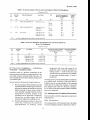
12.3 Accuracy Requirements
the seal
12.3.1
IN-SERVICE
Under Reference
Limits of error specified in Table 2 are applicable for
in-service
meters when tested under reference
conditions.
Testing
Metrological testing and functional verifications are
carried out on meters in service as per requirement of
relevant Indian standards:
a)
on receipt of consumer’s complaint or internal
report; and
b)
as part of in-service compliance
12.3.2
On-site Conditions
Limits of error stated in Table 3 are applicable when
in-service meters are tested on-site under specified
operating conditions.
inspection.
12.4 In-service
Methodology
12.2 Methods
a)
Compliance
Testing
for in-service testing is as per 12.7.
It is att economical
method of monitoring
and
determining whether a population of meters, installed
in-service for a number of years without attendance,
is continuing to operate in accordance with metrological
specifications and other fictional
requirements. It is
also to assign a performance
indicator
to the
population
so that appropriate
asset -management
decisions can be taken. The -results of in-service
compliance
testing shall be noted in the asset
management register.
of Testing
12.2.0 Meter testing can be carried out on-site or at a
meter test station, provided the test facility adopted
complies with IS/ISO/IEC 17025. All test equipment
shall be traceable to the National Standards. Meter for
LV installation maybe tested including CTS to get the
overall accuracy of the meter. Meter and CT/PT for
HV installation shall be tested separately.
12.2.1
Conditions
On-site testing may be carried out:
12.4.1 Initial Life/Compliance
under prevailing load, taking care that the load
and power factor satisfy the range as indicated
in Table 3;
b)
by injection method after connecting a suitable
phantom load or external load. For reactive
measurement, the test will be performed only
by this method; and
c)
by installing off-line check meter — The meter
of at least same or better accuracy class shall
be installed for minimum one billing cycle.
There shall be sufficient increment in the
energy register to ensure the accuracy is better
than 1/10 of the accuracy of the meter if the
error is found to be more than the Iimits as
specified in the Table 3.
Period
The initial life is determined in the design stage or
in the prototype
stage. This is done either from
prediction of reliability y from manufacturers’
data of
reliability of components
submitted at the time of
type approval or from accelerated
life testing of a
prototype.
If the initial life of a population is not certified for want
of data or absence of a notified body, the meter service
provider in the best interest of own asset management
and the consumers,
carries out initial in-service
compliance testing after completion of two years in
service so as to take care of any initial instability of
performance. Generally, it is done in the 3rd year and
the compliance period is reckoned from the initial year
of service.
On site testing of CTs and PT’s shall be carried
out using either by comparison with standard
instrument transformers
or by simulation
techniques using appropriate test equipment.
The connected burden shall be measured and
recorded and shall be verified to ensure that
it is commensurate with the rated burden of
the instrument transformer.
12.4.2
On-going
Compliance
After expiry of the initial life of meters of a particular
type, it may be extended on the basis of test data
collected from meters in the field or normally removed
meters. The life is thus continuously monitored and it
may be increased or decreased periodically depending
on the data.
NOTE — For reactive measurement, on-site accurzcy
test shall be by the injection test method using phantom
load kit.
In the absence of such data or the notified body, the
meter service provider shall carry out on-going inservice compliance tests after expiry of the initial
compliance period, so as to assign a new compliance
period.
12.2.2 Main, Check and Standby Meters
These shall be in accordance with CEA (Installation
and Operation of Meters) Regulations.
12
IS 15707:2006
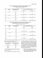
Table 2 In-service
Limits of Errors and Uncertainties
of Meter Test Equipment
(Clause 12.3.1)
sl
No.
Accuracy
Class
Type of Connection
Test Points
P.F.
Overall Uncertainty of
Meter Test Equipment
Percent
Limits of
Error
(1)
(2)
(3)
(4)
(5)
(6)
(7)
i)
2.0
Direct connectecVWith CTS
ii)
1,0/1.0s
iii)
Direct Connected/For
CTS
NOTE — cos Us/sin Q applicable for active/reactwe
1.0
*0.4
*2,0
0.5 lag
+0.6
+2.0
0.8 lead
+0,6
+2.0
1.0
*0.4
*l, o
10 percent fb
0.5 lag
*0,6
X1.o
i O percent f~
0.8 lead
+0.6
*1. O
1.0
+(). 1
10 percent f~ to [~,,1
0.5 lag
*0.12
+0.5
+0,6
10 percent f~ to [~,,,
0.8 lead
*0,12
*0,6
5 percent Ib to
Table 3 In-service
IM,,X
5 percent Ib to 1~,,.
For CT/VTs
0,5s
10 percent 1~to
Percent
fM,i.
energy respectively.
Maximum Permissible Errors and Uncertainties
Meter Test Equipment
of
{Clause 12.3.2)
sl
Accnracy
Class
Test Points
P.F.
No.
Overall Uncertainty-of Meter
Test Equipment (M.T.E.)
Percent
Maximum Permissible
Error (M.P.E.)
Percent
(1)
(2)
(3)
(4)
(5)
O
ii)
2.0
10percent 1~to [w,
1.0 and 0.5 lag
+0,6.
*3.()
1.0
10 percent Ib to t~u
1.0 and 0.5 lag
+0.4
*2.5
iii)
1.0s
5 percent 1~to [~,,
1.0 and 0.5 lag
*0.3
f2,0
iv)
0.5s
5 percent Ib to I~u
1.0 and 0.5 lag
*0.2
rl.o
(6)
NOTE— cos @/sin0 applicablefor active/reactive energy respectively.
12.5 In-service
Compliance
— Installation
Verification — Irrstaliaticm Audits
components
and wires with respect to its
application, meter enclosure authenticity of
sealing system — both verification
and
security seals, type of enclosure used, number
of seals used, whether number of seals is
justified etc.
Installation
audit is a periodic examination of the
metering system installation to assess the health of the
system and to ensure continued health of the same. All
meter installations need to be periodically audited under
asurveillance plan.
The energy service provider shall audit the installations
on a periodic basis. Periodicity of the audit shall be
defined as per the revenue potential of the metering
system (that is, for high value consumers, it should be
more frequent than to that of a domestic consumer).
For LV direct connected consumers suitable statistical
plan may be employed.
Various aspects to be observed during the audit are:
a)
b)
Physical examination of the installation, its health
in general and factors related to good installation
practices like neatness of installation, mounting
method, dressing of cables, colour coding of
wires, ferruling including following common
nomenclature
in ferrules, integrity of the
installation and its proneness to tampering,
observations
on safety aspects like bare
connections, naked joints, earthing etc; and
12.6 Implementation
of Compliance
Requirements
This Code -will be notified by appropriate
implementation.
authority for
12.6.1 Existing Meters
Detailed examination
related to electrical
nature like, correctness
of connections,
appropriateness
of metering
system
The existing meters will be deemed to have the initial
in-service compliance period as indicated in Table 4.
13
IS 15707:2006
Table 4 -Deemed Initial Compliance Period of
Meters In-service.(During
Implementation)
(Clause 12.6.1)
s]
No.
Accuracy
Class
(1)
(2)
(3)
i)
ii)
iii)
2.0 s
1.0/1.0 s
0.5 s
10
8
5
standard random number generation table. Damaged/
tampered
meters are to be excluded
from the
population selected.
In case a population
fails on the basis of single
sampling, additional samples may be taken to arrive at
conclusions
on the basis of corresponding
double
samples as given in Table 3A of IS 2500 (Part 1).
Deemed Initial Compliance
Period (Years)
‘
If any on site test shows that the meter is outside the
permissible error limits, investigation shall be made to
determine if it is due to .effe.ct of influence quantities or
the installation.
The meter shall be tested in the
laboratory and decision is to be based on results of
laboratory testing,
A population ofmcters which have outlived the deemed
initial compliance period, will bc tested for on-going
compliance
within
3 years from the year of
implementation of this Code.
Samples, if tested in a laboratory and found satisfactory,
will be put back in service after evaluation.
A population of meters which is within the deemed
initial compliance period, will be tested for on-going
in-service compliance within 1 year from the year of
expiry of the deemed initial compliance period.
12.7.5 Evaluation
Testing will be done on site or under
conditions to determine:
12.6.2 New Meters
A population of new-meters of any type will undergo
compliance testing in the third year after being placed
into service, in order to determine the initial in-service
compliance
period effective
from the year of
installations.
12.7 Methodology
of In-service
a)
Non-registration
b)
Meter constant;
c)
Specific functional
d)
Metrological
e)
Compliance period will be determined on the
basis of one of the methods to be selected by
a meter service provider
for its area of
operation;
f)
Non-compliant population of meters will be
removed from service within the period
indicated in Table 5 or Table 6; and
g)
However, to arrive at the final decision for
such a population, second sampling may be
carried out as per Table 3A of IS 2500 (Part 1)
and overall passlfail decisions may be taken
according y.
Compliance
Metrological
characteristics
and
functional
performance of meters under compliance requirements
are tested. It is generally done on the basis of a sampling
plan, with a selected no of test points and functional
characteristics.
12.7.1 Sampling Plan
12.7.2 Single sampling by attributes on the basis of
normal distribution is adopted in the present Code.
12.7.3 Population
Meters arc to be grouped in a population
a)
Manufacturer;
b)
Type;
c)
Year of installation;
d)
Geographic
e)
Overhead/7Jnderground
f)
Indoor/Outdoor
@
h)
Whether repaired; and
12.7.5.1
AQL)
based on:
Variable
with voltage alone;
criteria;
test points (minimum three);
error-band
nlethod
(constant
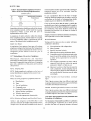
Table 5 gives accuracy class wise different initial and
on-going compliance periods to be assigned on the basis
of variable error-bands at fixed AQL.
area;
12.7.5.2
service;
Variable AQL method (constant error-band)
Table 6 gives accuracy class wise different initial and
on-going compliance periods to be assigned on the basis
of variable AQL for class-index error-bands.
installation;
Any other appropriate
reference
characteristic.
.12.7.4 Selection of Samples and Pass/Fail
12.8 Meter Test Equipment (M. T.E.) Standards and
Periodicity of Calibration
Criteria
For the purpose of dependable and effective calibration
and metrological
verification
by a meter service
provider, the latter will properly maintain calibrated
Tables 1 and 2A given in “IS 2500 (Part 1) will
determine selection of samples and pass/fail criteria.
Samples are to be selected at random on the basis of
14
..-.,..
“,...-..,
.--
—-—-
.
..-.
.
.
.
.
. . ..—
1S 15707:2006
Table 5 Initial and On-going Compliance Period of Meters In-service
(After Implementation by Fixed AQL Method)
(Clauses
SI
No.
Accuracy
Class
(1)
12.7.5 and 12.7.5.1)
Error-Bands in Class Index
Load and RF. Range
(2)
In-service Compliance
-
/
2.0
v)
vi)
vii)
viii)
1.0/1.0 s
ix)
x)
xi)
xii)
0.5s
-
Initial (AQL = I)
On-going (AQL -4)
(4)
(5)
(3)
i)
ii)
iii)
iv)
Period (Years)
*2.O
10
5
*2.5
+3.0
*4.O
7
4
To remove within 2 years
4
2
To remove within 2 years
*1.O
+1.5
+2.0
+3.0
8
5
3
To remove within 2 yews
4
3
2
To remove within 2 years
*0.5
+0.75
+1.0
*1.5
6
4
2
To remove within 1 year
3
2
1
To remove within 1 year
Table 6 Initial and On-going Compliance Period of Meters In-service
(After Implementation by Fixed Error Band Method)
(Clauses
s!
Accuracy
Class
No.
12.7.5 and 12.7.5.2)
AQL for the Class Index
Error Band
In-service Compliance
—
/
Initial
Period (Years)
Ongoing
(1)
(2)
(3)
(4)
i)
ii)
iii)
iv)
2.0
1.0
2.5
10
7
5
4
4
To remove within 2 years
—
2
To remove within 2 years
1.0
2.5
8
5
4
4.0
3
3
To remove within 2 years
2
To remove within 2 years
4.0
6.5
10
v)
vi)
vii)
viii)
ix)
1.0/1.0 s
6.5
10
x)
0.5s
xi)
xii)
xiii)
xiv)
xv)
1.0
(5)
6
2.5
4
3
4.0
2
2
To remove within I year
1
To remove within 1 year
6.5
10
be partially complying to its specification, the use of
the working standard shall be restricted to working
range and class only. When a working standard is
calibrated and is found to be outside its specification,
its use shall be immediately stopped. The reason shall
be investigated and the occurrence reported within 3
working days of its discovery. Notification shall be
given of the details and results of the investigation. The
result of the investigation shows:
standards in its meter testing station. The accuracy class
of meter test equipment shall be as follows:
Accuracy Class of
Meter Under Test
Accuracy Class of Meter
Test Equipment
(1)
(2]
2.0 s
1.0/1.0 s
0.5 s
0.3
0.2
0.1
Various standards and their periodicity
are shown in Table 7.
of calibration
When a working standard is calibrated
and is found to
a)
15
Whether metering equipment calibrated or
tested using that working standard since its
last satisfactory calibration complies with the
relevant standard document; and
IS 15707:2006
Table7
Periodicity
of Calibration
of Various Standards ofa Meter Test Station
(Clause 12.8)
sl
Energy Standards
(Maintained
Calibration
in M.T.S.)
No.
/
(1)
Remarks
\
Normal
Extended
(3)
(4)
(2)
Reference standard
Interval (Months)
A
24
(External calibration only)
(5)
Stability to be monitored
i)
ii)
ac/dc transfer standard (External calibration)
24
60
Depending on stability
iii)
ac/dc transfer standard (In-house calibration)
Prior to use
6
Depending on stability
iv)
ac transfer standard (When used in-house)
ac transferstandard(Whenused on-site)
2
6
Before and after use
Depending on stability
—
6
Depending on stabi lity
v)
vi)
vii)
b)
Working standard (Optional external calibration)
12
Working standard (In-house calibration)
2
The reason why that working
outside its specification.
i)
2)
standard
Table 5 or Table 6 for on-going compliance
requirements.
is
Location
— It does not require the
Standards of any meter operator agent to
be maintained or used at anyone location,
and
15 DI-SPOSAL
Meters shall be systematically disposed off at the end
of their useful life, on obsolescence or when declared
irreparable/uneconomical
to repair during its service
life. Such meters shall be scrapped and disposed off
taking care that no part is left in re-usable or recyclable
form. It shall be ensured that meter identification plates/
labels are destroyed
and recorded
into the asset
management
system. Special disposal actions, as
applicable, shall be adopted for hazardous material/
components
like lithium batteries,
magnets, lead
containing parts, etc.
Mobility — Reference standards and acl
dc transfer standards shall not be mobile
standards and shall remain in one location
as far as possible and only be moved for
verification at an accredited laboratory.
NOTE — ac transfer standards and working
standards may be mobile standards.
13 REPAIR
At the end of useful life considering all the extensions,
or at the end of in-service compliance period, a meter
is removed. The next action is either refurbishment/
repair in a workshop belonging to the service provider,
manufacturer or a third party. Otherwise it may be
disposed off.
The decision
considerations
a)
taken is centered
involving:
Remaining
16 ASSET AND SEAL MANAGEMENT”SYSTEM
16.1 Asset Management
An asset management system shall be maintained for
keeping records in order to ensure that the life cycle
history of meters is traceable from the point of first
installation.
The details of the consumer number/
consumer name and address against which the meters
are issued shall be maintained in the stores and the
meters shall only be issued against the consumer
number/consumer name issued from the stores.
on economical
useful life after repair;
b)
Cost of repair; and
c)
Asset disposal value.
The register shall contain information on meter serial
number, energy service provider
assigned serial
number, procurement reference (for example, purchase
order number), sealing details, manufacturer’s name,
year of manufacture, type of meter, meter constant,
accuracy class, current rating, installation site reference
and date of installation, test results or reference to test
results(accuracy
test, dial test), initial reading,
information about auxiliary~quipment
Iike CT/VT and
their ratings. The asset register should preferably be in
electronic form with features of traceability of the
history of the metering installation.
14 RE-CERTI-FICATION/RE-VERIFICATION/
IN+ERVICE
RE-COMPLIANCE
After refurbishment/repair
of meters removed from
service, it is required as a good practice that these are:
a)
Re-certified
by the notified body for the
remaining portion of useful life;
b)
Re-verified by the notified body and the seals
applied; and
c)
Inspected for in-service re-compliance testing
and re-compliance period determined as per
—
16
1S 15707:2006
Status of initial and on-going compliance should be
indicated in the register with reference to test data of
the samples.
c)
Seals when removed, leave detectable evidence;
d)
Procurement, stocking, issue, installation and
disposal of seals is traceable;
Records of returned meter are also to be maintained.
All the details of old meters are to be entered in the
register when the old meter comes to the store.
e)
Traceability should be uniquely
to a responsible individual;
f)
All numbered seals are traceable to consumers
through meter numbers;
16.2 Seal Management
g)
h)
Seals are secured against misuse;
j)
Seal Management system itself is secure with
proper access control.
The energy service provider
shall maintain
an
appropriate
seal management
system. The seal
management
system ensures that seals are secure,
controlled, uniquely identified and traceable.
A seal management
Seals are unique and distinctive for each
manufacturer/energy
service provider;
b)
Seals are not easily imitable;
Sealing punch, when used shall be uniquely
identifiable and traceable; and
All numbered seals should be traceable to consumers
through meter numbers. All broken seals shall be
disposed off taking care that the seals are destroyed so
that they cannot be re-used. Proper records of such
disposal shall be maintained.
system shall ensure the following:
a)
identifiable
17
..
.
. ..
. .
.
Bureau of Indian Standards
BIS is a statutory institution
established
under the Bureau
harmonious
development
of the activities of standardization,
and attending to connected matters in the country.
of Indian Standards Act, 1986 to promote
marking and quality certification
of goods
Copyright
BIS has the copyright of all its publications. No part of these publications may be reproduced in any form
without the prior permission
in writing of BIS. This does not preclude the free use, in the course of
implementing
the standard, of necessary details, such as symbols and sizes, type or grade designations.
Enquiries relating to copyright be addressed to the Director (Publications), BIS.
Review of Indian Standards
Amendments are issued to standards as the need arises on the basis of comments. Standards are also reviewed
periodically; a standard along with amendments is reaffirmed when such review indicates that no changes are
needed; if the review indicates that changes are needed, it is taken Mp for revision. Users of Indian Standards
should ascertain that they are in possession of the latest amendments or edition by referring to the latest issue of
‘BIS Catalogue’ and ‘Standards : Monthly Additions’.
This Indian Standard has been developed
from Doc : No. ET 13 (5659).
Amendments
Amend No.
Issued Since Publication
Date of Issue
Text Affected
BUREAU OF “INDIAN STANDARDS
Headquarters
:
Manak Bhavan, 9 Bahadur Shah Zafar Marg, New Delhi 110002
Telephones :23230131,23233375,2323
9402
Telegrams : Manaksanstha
(Common to all offices)
Regional Offices :
Telephone
Central
: Manak Bhavan, 9 Bahadur Shah Zafar Marg
NEW DELHI 110002
Eastern
: 1/14 C.I.T. Scheme VII M, V. 1. P. Road, Kankurgachi
KOLKATA 700054
Northern
: SCO 335-336, Sector 34-A, CHANDIGARH
23237617
{ 23233841
23378499,23378561
{ 23378626,23379120
160022
‘{
2603843
2609285
Southern
: C.I.T. Campus, IV Cross Road, CHENNAI 600113
22541216,22541442
{ 22542519,22542315
Western
: Manakalaya, E9 MIDC, Marol, Andheri (East)
MUMBAI 400093
28329295,28327858
{ 28327891,28327892
Branches
: AHMEDABAD. BANGALORE. BHOPAL,. BHUBANESHWAR.
COIMBATORE. FARIIIABAD.
GHAZIABAD.
GUWAHATI.
HYDERABAD.
JAIPU~. KANPUR. LUCKNOW.
NAGPUR.
NALAGARH. PATNA. PUNE. RAJKOT. THIRUVANANTHAPURAM.
VISAKHAPATNAM.
Printed at Rabhat Offset Press, New Dethi-;