1
Cisco 7200 VXR Installation and
Configuration Guide
Corporate Headquarters
Cisco Systems, Inc.
170 West Tasman Drive
San Jose, CA 95134-1706
USA
http://www.cisco.com
Tel: 408 526-4000
800 553-NETS (6387)
Fax: 408 526-4100
Customer Order Number:
Text Part Number: OL-5013-08
THE SPECIFICATIONS AND INFORMATION REGARDING THE PRODUCTS IN THIS MANUAL ARE SUBJECT TO CHANGE WITHOUT NOTICE. ALL
STATEMENTS, INFORMATION, AND RECOMMENDATIONS IN THIS MANUAL ARE BELIEVED TO BE ACCURATE BUT ARE PRESENTED WITHOUT
WARRANTY OF ANY KIND, EXPRESS OR IMPLIED. USERS MUST TAKE FULL RESPONSIBILITY FOR THEIR APPLICATION OF ANY PRODUCTS.
THE SOFTWARE LICENSE AND LIMITED WARRANTY FOR THE ACCOMPANYING PRODUCT ARE SET FORTH IN THE INFORMATION PACKET THAT
SHIPPED WITH THE PRODUCT AND ARE INCORPORATED HEREIN BY THIS REFERENCE. IF YOU ARE UNABLE TO LOCATE THE SOFTWARE LICENSE
OR LIMITED WARRANTY, CONTACT YOUR CISCO REPRESENTATIVE FOR A COPY.
The following information is for FCC compliance of Class A devices: This equipment has been tested and found to comply with the limits for a Class A digital device, pursuant
to part 15 of the FCC rules. These limits are designed to provide reasonable protection against harmful interference when the equipment is operated in a commercial
environment. This equipment generates, uses, and can radiate radio-frequency energy and, if not installed and used in accordance with the instruction manual, may cause
harmful interference to radio communications. Operation of this equipment in a residential area is likely to cause harmful interference, in which case users will be required
to correct the interference at their own expense.
The following information is for FCC compliance of Class B devices: The equipment described in this manual generates and may radiate radio-frequency energy. If it is not
installed in accordance with Cisco’s installation instructions, it may cause interference with radio and television reception. This equipment has been tested and found to
comply with the limits for a Class B digital device in accordance with the specifications in part 15 of the FCC rules. These specifications are designed to provide reasonable
protection against such interference in a residential installation. However, there is no guarantee that interference will not occur in a particular installation.
Modifying the equipment without Cisco’s written authorization may result in the equipment no longer complying with FCC requirements for Class A or Class B digital
devices. In that event, your right to use the equipment may be limited by FCC regulations, and you may be required to correct any interference to radio or television
communications at your own expense.
You can determine whether your equipment is causing interference by turning it off. If the interference stops, it was probably caused by the Cisco equipment or one of its
peripheral devices. If the equipment causes interference to radio or television reception, try to correct the interference by using one or more of the following measures:
• Turn the television or radio antenna until the interference stops.
• Move the equipment to one side or the other of the television or radio.
• Move the equipment farther away from the television or radio.
• Plug the equipment into an outlet that is on a different circuit from the television or radio. (That is, make certain the equipment and the television or radio are on circuits
controlled by different circuit breakers or fuses.)
Modifications to this product not authorized by Cisco Systems, Inc. could void the FCC approval and negate your authority to operate the product.
The Cisco implementation of TCP header compression is an adaptation of a program developed by the University of California, Berkeley (UCB) as part of UCB’s public
domain version of the UNIX operating system. All rights reserved. Copyright © 1981, Regents of the University of California.
NOTWITHSTANDING ANY OTHER WARRANTY HEREIN, ALL DOCUMENT FILES AND SOFTWARE OF THESE SUPPLIERS ARE PROVIDED “AS IS” WITH
ALL FAULTS. CISCO AND THE ABOVE-NAMED SUPPLIERS DISCLAIM ALL WARRANTIES, EXPRESSED OR IMPLIED, INCLUDING, WITHOUT
LIMITATION, THOSE OF MERCHANTABILITY, FITNESS FOR A PARTICULAR PURPOSE AND NONINFRINGEMENT OR ARISING FROM A COURSE OF
DEALING, USAGE, OR TRADE PRACTICE.
IN NO EVENT SHALL CISCO OR ITS SUPPLIERS BE LIABLE FOR ANY INDIRECT, SPECIAL, CONSEQUENTIAL, OR INCIDENTAL DAMAGES, INCLUDING,
WITHOUT LIMITATION, LOST PROFITS OR LOSS OR DAMAGE TO DATA ARISING OUT OF THE USE OR INABILITY TO USE THIS MANUAL, EVEN IF CISCO
OR ITS SUPPLIERS HAVE BEEN ADVISED OF THE POSSIBILITY OF SUCH DAMAGES.
Cisco 7200 VXR Installation and Configuration Guide
Copyright © 1998–2006 Cisco Systems, Inc. All rights reserved.
CONTENTS
Preface
ix
Document Revision History
Audience
ix
ix
Organization
x
Document Conventions x
Warning Definition xii
Terms and Acronyms
xv
Related Documentation
xvi
Obtaining Documentation xvii
Cisco.com xvii
Product Documentation DVD xvii
Ordering Documentation xvii
Documentation Feedback
xviii
Cisco Product Security Overview xviii
Reporting Security Problems in Cisco Products
xviii
Obtaining Technical Assistance xix
Cisco Technical Support & Documentation Website
Submitting a Service Request xx
Definitions of Service Request Severity xx
Obtaining Additional Publications and Information
CHAPTER
1
Cisco 7200 VXR Product Overview
Physical Description
xix
xx
1-1
1-1
Software Requirements
1-4
Cisco 7204VXR Overview
1-4
Cisco 7206VXR Overview
1-7
Field-Replaceable Units 1-10
Network Processing Engine or Network Services Engine
Input/Output Controller 1-32
LED Descriptions 1-40
NPE-G2 LEDs 1-41
NPE-G1 LEDs 1-42
Input/Output Controller C7200-I/O LEDs 1-43
1-11
Cisco 7200 VXR Installation and Configuration Guide
OL-5013-08
iii
Contents
Input/Output Controller C7200-I/O-GE+E LEDs 1-43
Input/Output Controller C7200-I/O-2FE/E LEDs 1-44
Input/Output Controller C7200-I/O-FE LEDs 1-45
Input/Output Controller C7200-I/O-FE-MII LEDs 1-47
Port Adapters and Service Adapters 1-47
Port Adapter Jacket Card 1-48
Power Supplies 1-49
Chassis 1-51
CompactFlash Disks, Flash Disks, and PC Cards 1-52
Rack-Mount and Cable-Management Kit 1-53
Functional Overview 1-54
Chassis Slot and Logical Interface Numbering 1-54
MAC Address 1-57
Online Insertion and Removal 1-57
Environmental Monitoring and Reporting Functions 1-59
Environmental Monitoring 1-59
Reporting Functions 1-62
Fan Failures 1-64
CHAPTER
2
Preparing for Installation
Tools and Parts Required
2-1
2-1
Electrical Equipment Guidelines
2-2
Preventing Electrostatic Discharge Damage
2-2
Site Requirement Guidelines 2-3
Rack-Mounting Guidelines 2-5
Temperature and Humidity Requirements 2-7
Power Connection Guidelines 2-8
Plant Wiring Guidelines 2-8
Interference Considerations 2-8
Distance Limitations and Interface Specifications
Initial Configuration Information
2-9
Cisco 7200 VXR Router Installation Checklist
Checking the Shipping Container Contents
Site Log
CHAPTER
3
2-9
2-10
2-12
2-13
Installing a Cisco 7200 VXR Router
3-1
Rack-Mounting a Cisco 7200 VXR Router 3-2
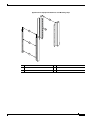
Attaching the Chassis Rack-Mount and Cable-Management Brackets
3-7
Cisco 7200 VXR Installation and Configuration Guide
iv
OL-5013-08
Contents
Installing the Brackets on the Front of the Chassis 3-8
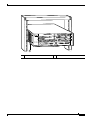
Installing the NPE-G1 and NPE-G2 Cable-Management Brackets on a Front-Mounted
Router 3-9
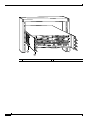
Installing the NPE-G1 and NPE-G2 Optical Cable-Management Bracket 3-11
Installing the Brackets on the Rear of the Chassis 3-11
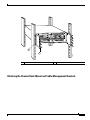
Installing the NPE-G1 and NPE-G2 Cable-Management Brackets on a Rear-Mounted
Router 3-13
Installing the Chassis in the Rack 3-14
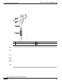
General Tabletop or Workbench Installation
3-14
Installing the Cable-Management Brackets 3-15
Securing the Port Adapter Cables 3-16
Attaching a Chassis Ground Connection
Connecting Port Adapter Cables
3-17
3-19
Connecting I/O Controller, NPE-G1, or NPE-G2 Cables 3-19
Connecting to Gigabit Ethernet Slots and Ports 3-19
Gigabit Ethernet SFP Module Connections 3-20
Mode-Conditioning Patch Cord Description 3-23
Gigabit Ethernet GBIC Connections 3-24
GBIC Cabling and Connection Equipment 3-26
Mode-Conditioning Patch Cord Description 3-28
Gigabit Ethernet RJ-45 Connections on the NPE-G1 and NPE-G2 3-29
Connecting to the I/O Controller Ethernet and Fast Ethernet Ports 3-30
Ethernet and Fast Ethernet RJ-45 Connections 3-30
Fast Ethernet MII Connections 3-33
Connecting to the Console and Auxiliary Ports 3-34
DB-25 Port Cabling and Pinouts 3-35
RJ-45 Port Cabling and Pinouts 3-37
Connecting Power 3-41
Connecting AC-Input Power
Connecting DC-Input Power
CHAPTER
4
3-42
3-42
Observing System Startup and Performing a Basic Configuration
Checking Conditions Prior to System Startup
4-1
4-1
Starting the System and Observing Initial Conditions
4-2
Configuring a Cisco 7200 VXR Router 4-3
Performing a Basic Configuration Using AutoInstall 4-4
Performing a Basic Configuration Using the Setup Facility 4-4
Configuring Global Parameters 4-5
Configuring the Native Gigabit Ethernet Interfaces 4-8
Cisco 7200 VXR Installation and Configuration Guide
OL-5013-08
v
Contents
Configuring the Interface Transmission and Speed Modes 4-8
Sample Configuration 4-9
Debugging 4-10
Resetting the Interface on the NPE-G1 or NPE-G2 4-10
Clearing Counters on the NPE-G1 or NPE-G2 4-10
Configuring Port Adapter Interfaces 4-10
Configuring ATM Interfaces 4-10
Configuring Fast Ethernet Interfaces 4-11
Configuring Synchronous Serial Interfaces 4-12
Performing a Basic Configuration Using Global Configuration Mode 4-14
Saving the Running Configuration to NVRAM 4-15
Checking the Running Configuration Settings 4-15
Performing Other Configuration Tasks
4-15
Using show Commands to Check the Installation
4-16
Replacing or Recovering a Lost Password 4-17
Overview of the Password Recovery Procedure 4-17
Details of the Password Recovery Procedure 4-18
CHAPTER
5
Viewing Your System Configuration
4-20
Performing Complex Configurations
4-22
Troubleshooting the Installation
5-1
Troubleshooting Overview 5-1
Problem Solving Using a Subsystems Approach
Identifying Startup Problems 5-3
Fans Operating 5-3
Power LEDs 5-3
I/O Controller LEDs 5-4
NPE-G1 or NPE-G2 LEDs 5-5
Port Adapter Jacket Card LEDs 5-6
Port Adapter LEDs 5-6
System Bootup Banner 5-6
Troubleshooting the Power Subsystem
5-2
5-6
Troubleshooting the Processor Subsystem 5-7
Troubleshooting the I/O Controller 5-7
Troubleshooting the NPE-G1 or NPE-G2 5-8
Troubleshooting the Network Processing Engine or Network Services Engine
Troubleshooting the Port Adapter Jacket Card 5-9
Troubleshooting the Port Adapters or Service Adapters 5-9
Troubleshooting the Cooling Subsystem
5-9
5-10
Cisco 7200 VXR Installation and Configuration Guide
vi
OL-5013-08
Contents
Fiber-Optic Cleaning Information
APPENDIX
A
Configuration Register Information
Configuration Bit Meanings
Bits 0–3 A-2
Bit 6 A-3
Bit 7 A-3
Bit 8 A-4
Bit 10 and Bit 14 A-4
Bit 11 and Bit 12 A-4
Bit 13 A-4
Bit 15 A-5
5-10
A-1
A-1
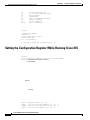
Displaying the Configuration Register While Running Cisco IOS
A-5
Displaying the Configuration Register While Running ROM Monitor
Setting the Configuration Register While Running Cisco IOS
A-5
A-6
Setting the Configuration Register While Running ROM Monitor
A-6
INDEX
Cisco 7200 VXR Installation and Configuration Guide
OL-5013-08
vii
Contents
Cisco 7200 VXR Installation and Configuration Guide
viii
OL-5013-08
Preface
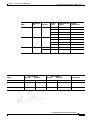
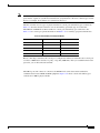
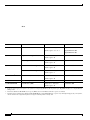
Document Revision History
The Document Revision History beginning with this online part number, records technical changes to
this document.
Document Version
Date
Change Summary
OL-5013-07
December, 2006
Adding NPE-G2 CWDM information.
OL-5013-07
May, 2006
Adding the NPE-G2 information.
OL-5013-06
March, 2006
Adding the Port Adapter Jacket Card and new NPE-G1
temperature threshold information.
OL-5013-05
September, 2005
This version removes the MEM-I/O-D-FLD32M and the
MEM-I/O-D-FLD48M product identification from the
document, as the part is end-of-sale, and adds statement
numbers to warnings.
This preface describes who should read the Cisco 7200 VXR Installation and Configuration Guide
it is organized, and its document conventions.
Cisco documentation and additional literature are available in the Product Documentation DVD package,
which may have shipped with your product. The Product Documentation DVD is updated regularly and
may be more current than printed documentation. See “Product Documentation DVD” section on
page xvii for more information.
You can access the most current Cisco documentation on the World Wide Web at http://www.cisco.com.
Translated documentation is available at http://www.cisco.com/public/countries_languages.shtml.
Audience
ix
Preface
Organization
the Cisco 7200 VXR routers. It contains procedures for unpacking and installing the router hardware,
creating a basic software configuration file, and starting up the router. After completing the installation
and basic configuration procedures covered in this guide, you will then use the appropriate companion
publications to more completely configure your system.
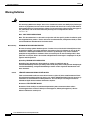
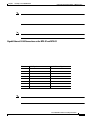
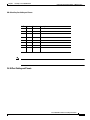
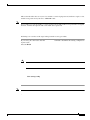
Organization
The major sections of this guide are as follows:
Chapter
Title
Description
Describes safety considerations, tools required, and gives
an overview of the installation and procedures you should
perform before
Chapter 4
Observing System
Describes the procedures for completing a basic system
Startup and Performing a configuration and for checking and saving this
Basic Configuration
configuration to system memory.
Chapter 5
Troubleshooting the
Installation
Describes troubleshooting procedures for the hardware
installation.
Appendix A
Configuration Register
Information
Provides configuration register information.
Document Conventions
boldface
boldface
[ ]
Elements in square brackets are optional.
{x|y|z}
Alternative keywords are grouped in braces and separated by vertical bars.
[x|y|z]
Optional alternative keywords are grouped in brackets and separated by
vertical bars.
string
A nonquoted set of characters. Do not use quotation marks around the string,
or the string will include the quotation marks.
Document Conventions
screen
boldface screen
italic screen
Note
Caution
screen
boldface screen
italic screen
^
The symbol ^ represents the key labeled Control—for example, the key
combination ^D
Control
D
< >
Nonprinting characters, such as passwords, are in angle brackets.
[ ]
Default responses to system prompts are in square brackets.
!, #
An exclamation point (!) or a pound sign (#) at the beginning of a line of code
indicates a comment line.
reader take note
Preface
Document Conventions
Warning Definition
Warning
IMPORTANT SAFETY INSTRUCTIONS
This warning symbol means danger. You are in a situation that could cause bodily injury. Before you
work on any equipment, be aware of the hazards involved with electrical circuitry and be familiar
with standard practices for preventing accidents. To see translations of the warnings that appear in
this publication, refer to the translated safety warnings that accompanied this device.
Statement 1071
Note: SAVE THESE INSTRUCTIONS
Note: This documentation is to be used in conjunction with the specific product installation guide
that shipped with the product. Please refer to the Installation Guide, Configuration Guide, or other
enclosed additional documentation for further details.
Waarschuwing
BELANGRIJKE VEILIGHEIDSINSTRUCTIES
Dit waarschuwingssymbool betekent gevaar. U verkeert in een situatie die lichamelijk letsel kan
veroorzaken. Voordat u aan enige apparatuur gaat werken, dient u zich bewust te zijn van de bij
elektrische schakelingen betrokken risico's en dient u op de hoogte te zijn van de standaard
praktijken om ongelukken te voorkomen. Voor een vertaling van de waarschuwingen die in deze
publicatie verschijnen, dient u de vertaalde veiligheidswaarschuwingen te raadplegen die bij dit
apparaat worden geleverd.
Opmerking BEWAAR DEZE INSTRUCTIES.
Opmerking Deze documentatie dient gebruikt te worden in combinatie met de
installatiehandleiding voor het specifieke product die bij het product wordt geleverd. Raadpleeg de
installatiehandleiding, configuratiehandleiding of andere verdere ingesloten documentatie voor
meer informatie.
Varoitus
TÄRKEITÄ TURVALLISUUTEEN LIITTYVIÄ OHJEITA
Tämä varoitusmerkki merkitsee vaaraa. Olet tilanteessa, joka voi johtaa ruumiinvammaan. Ennen
kuin työskentelet minkään laitteiston parissa, ota selvää sähkökytkentöihin liittyvistä vaaroista ja
tavanomaisista onnettomuuksien ehkäisykeinoista. Tässä asiakirjassa esitettyjen varoitusten
käännökset löydät laitteen mukana toimitetuista ohjeista.
Huomautus SÄILYTÄ NÄMÄ OHJEET
Huomautus Tämä asiakirja on tarkoitettu käytettäväksi yhdessä tuotteen mukana tulleen
asennusoppaan kanssa. Katso lisätietoja asennusoppaasta, kokoonpano-oppaasta ja muista
mukana toimitetuista asiakirjoista.
Cisco 7200 VXR Installation and Configuration Guide
OL-5013-08
Preface
Document Conventions
Attention
IMPORTANTES INFORMATIONS DE SÉCURITÉ
Ce symbole d'avertissement indique un danger. Vous vous trouvez dans une situation pouvant causer
des blessures ou des dommages corporels. Avant de travailler sur un équipement, soyez conscient
des dangers posés par les circuits électriques et familiarisez-vous avec les procédures couramment
utilisées pour éviter les accidents. Pour prendre connaissance des traductions d'avertissements
figurant dans cette publication, consultez les consignes de sécurité traduites qui accompagnent cet
appareil.
Remarque CONSERVEZ CES INFORMATIONS
Remarque Cette documentation doit être utilisée avec le guide spécifique d'installation du produit
qui accompagne ce dernier. Veuillez vous reporter au Guide d'installation, au Guide de
configuration, ou à toute autre documentation jointe pour de plus amples renseignements.
Warnung
WICHTIGE SICHERHEITSANWEISUNGEN
Dieses Warnsymbol bedeutet Gefahr. Sie befinden sich in einer Situation, die zu einer
Körperverletzung führen könnte. Bevor Sie mit der Arbeit an irgendeinem Gerät beginnen, seien Sie
sich der mit elektrischen Stromkreisen verbundenen Gefahren und der Standardpraktiken zur
Vermeidung von Unfällen bewusst. Übersetzungen der in dieser Veröffentlichung enthaltenen
Warnhinweise sind im Lieferumfang des Geräts enthalten.
Hinweis BEWAHREN SIE DIESE SICHERHEITSANWEISUNGEN AUF
Hinweis Dieses Handbuch ist zum Gebrauch in Verbindung mit dem Installationshandbuch für Ihr
Gerät bestimmt, das dem Gerät beiliegt. Entnehmen Sie bitte alle weiteren Informationen dem
Handbuch (Installations- oder Konfigurationshandbuch o. Ä.) für Ihr spezifisches Gerät.
Avvertenza
IMPORTANTI ISTRUZIONI SULLA SICUREZZA
Questo simbolo di avvertenza indica un pericolo. La situazione potrebbe causare infortuni alle
persone. Prima di intervenire su qualsiasi apparecchiatura, occorre essere al corrente dei pericoli
relativi ai circuiti elettrici e conoscere le procedure standard per la prevenzione di incidenti. Per le
traduzioni delle avvertenze riportate in questo documento, vedere le avvertenze di sicurezza che
accompagnano questo dispositivo.
Nota CONSERVARE QUESTE ISTRUZIONI
Nota La presente documentazione va usata congiuntamente alla guida di installazione specifica
spedita con il prodotto. Per maggiori informazioni, consultare la Guida all'installazione, la Guida
alla configurazione o altra documentazione acclusa.
Cisco 7200 VXR Installation and Configuration Guide
OL-5013-08
Preface
Document Conventions
Advarsel
VIKTIGE SIKKERHETSINSTRUKSJONER
Dette varselssymbolet betyr fare. Du befinner deg i en situasjon som kan forårsake personskade.
Før du utfører arbeid med utstyret, bør du være oppmerksom på farene som er forbundet med
elektriske kretssystemer, og du bør være kjent med vanlig praksis for å unngå ulykker. For å se
oversettelser av advarslene i denne publikasjonen, se de oversatte sikkerhetsvarslene som følger
med denne enheten.
Merk TA VARE PÅ DISSE INSTRUKSJONENE
Merk Denne dokumentasjonen skal brukes i forbindelse med den spesifikke
installasjonsveiledningen som fulgte med produktet. Vennligst se installasjonsveiledningen,
konfigureringsveiledningen eller annen vedlagt tilleggsdokumentasjon for detaljer.
Aviso
INSTRUÇÕES IMPORTANTES DE SEGURANÇA
Este símbolo de aviso significa perigo. O utilizador encontra-se numa situação que poderá ser
causadora de lesões corporais. Antes de iniciar a utilização de qualquer equipamento, tenha em
atenção os perigos envolvidos no manuseamento de circuitos eléctricos e familiarize-se com as
práticas habituais de prevenção de acidentes. Para ver traduções dos avisos incluídos nesta
publicação, consulte os avisos de segurança traduzidos que acompanham este dispositivo.
Nota GUARDE ESTAS INSTRUÇÕES
Nota Esta documentação destina-se a ser utilizada em conjunto com o manual de instalação
incluído com o produto específico. Consulte o manual de instalação, o manual de configuração ou
outra documentação adicional inclusa, para obter mais informações.
¡Advertencia!
INSTRUCCIONES IMPORTANTES DE SEGURIDAD
Este símbolo de aviso indica peligro. Existe riesgo para su integridad física. Antes de manipular
cualquier equipo, considere los riesgos de la corriente eléctrica y familiarícese con los
procedimientos estándar de prevención de accidentes. Vea las traducciones de las advertencias
que acompañan a este dispositivo.
Nota GUARDE ESTAS INSTRUCCIONES
Nota Esta documentación está pensada para ser utilizada con la guía de instalación del producto
que lo acompaña. Si necesita más detalles, consulte la Guía de instalación, la Guía de
configuración o cualquier documentación adicional adjunta.
Varning!
VIKTIGA SÄKERHETSANVISNINGAR
Denna varningssignal signalerar fara. Du befinner dig i en situation som kan leda till personskada.
Innan du utför arbete på någon utrustning måste du vara medveten om farorna med elkretsar och
känna till vanliga förfaranden för att förebygga olyckor. Se översättningarna av de
varningsmeddelanden som finns i denna publikation, och se de översatta säkerhetsvarningarna som
medföljer denna anordning.
OBS! SPARA DESSA ANVISNINGAR
OBS! Denna dokumentation ska användas i samband med den specifika
produktinstallationshandbok som medföljde produkten. Se installationshandboken,
konfigurationshandboken eller annan bifogad ytterligare dokumentation för närmare detaljer.
Cisco 7200 VXR Installation and Configuration Guide
OL-5013-08
Preface
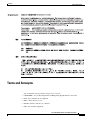
Terms and Acronyms
Terms and Acronyms
•
data; found either incorporated into the processor or near it.
•
CWDM GBIC—Coarse Wavelength-Divison Multiplexing Gigabit Interface Converter
•
DCE—data communications equipment
•
DMA—direct memory access
•
DRAM—dynamic random-access memory
•
DTE—data terminal equipment
Cisco 7200 VXR Installation and Configuration Guide
OL-5013-08
Preface
Related Documentation
•
EPROM—erasable programmable read-only memory
•
FRU—field-replaceable unit (router components that do not require replacement by a
Cisco-certified service provider)
GBIC—Gigabit Interface Converter
Gbps—gigabits per second
Instruction and data cache—Instructions to the processor and data on which the instructions work.
Integrated cache—Cache that is built into the processor; sometimes referred to as internal cache.
Cache memory that is physically located outside the processor is not integrated, and is sometimes
referred to as external cache.
MB—megabyte
NVRAM—nonvolatile random-access memory
OIR—online insertion and removal
PCI—Peripheral Component Interconnect
PCMCIA—Personal Computer Memory Card International Association
Primary, secondary, tertiary cache—Hierarchical cache memory storage based on the proximity of
the cache to the core of the processor. Primary cache is closest to the processor core and has the
fastest access. Secondary cache has slower access than primary cache, but faster access than tertiary
cache.
RFI—radio frequency interference
RISC—reduced instruction set computing
SDRAM—synchronous dynamic random-access memory
SIMM—single in-line memory module
SNMP—Simple Network Management Protocol
SRAM—static random-access memory
TFTP—Trivial File Transfer Protocol
Unified cache—Instruction cache and data cache are combined. For example, a processor may have
primary cache with separate instruction and data cache memory, but unified secondary cache.
Related Documentation
Your Cisco 7200 VXR router and the Cisco IOS software running on it contain extensive features and
functionality, which are documented in the following resources:
•
Cisco 7200 Series Routers Documentation Roadmap
http://www.cisco.com/en/US/products/hw/routers/ps341/products_documentation_roadmap09186a
00801c0915.html for a list of all Cisco 7200 series routers documentation and troubleshooting tools
and information.
Cisco 7200 Series Routers Port Adapter Documentation Roadmap
Cisco 7200 Series Routers Troubleshooting Documentation Roadmap
Cisco 7200 VXR Installation and Configuration Guide
OL-5013-08
Obtaining Documentation
Obtaining Documentation
Cisco.com
Product Documentation DVD
DOC-DOCDVD=) from Cisco Marketplace at this URL:
http://www.cisco.com/go/marketplace/
Ordering Documentation
[email protected] or by fax at 1 408 519-5001 in the United States and Canada,
or elsewhere at 011 408 519-5001.
Documentation Feedback
Documentation Feedback
Cisco Product Security Overview
•
•
•
Reporting Security Problems in Cisco Products
•
•
•
•
Preface
Obtaining Technical Assistance
Tip
x
x
Obtaining Technical Assistance
Technical Support & Documentation website on Cisco.com features extensive online support resources.
In addition, if you have a valid Cisco service contract, Cisco Technical Assistance Center (TAC)
engineers provide telephone support. If you do not have a valid Cisco service contract, contact your
reseller.
Cisco Technical Support & Documentation Website
Note
Tools & Resources
Cisco Product Identification Tool
Product Identification Tool
Cisco
show
Cisco 7200 VXR Installation and Configuration Guide
OL-5013-08
Submitting a Service Request
Asia-Pacific: +61 2 8446 7411 (Australia: 1 800 805 227)
EMEA: +32 2 704 55 55
USA: 1 800 553-2447
For a complete list of Cisco TAC contacts, go to this URL:
http://www.cisco.com/techsupport/contacts
To ensure that all service requests are reported in a standard format, Cisco has established severity
definitions.
Severity 1 (S1)—Your network is “down,” or there is a critical impact to your business operations. You
and Cisco will commit all necessary resources around the clock to resolve the situation.
Severity 2 (S2)—Operation of an existing network is severely degraded, or significant aspects of your
business operation are negatively affected by inadequate performance of Cisco products. You and Cisco
will commit full-time resources during normal business hours to resolve the situation.
Severity 3 (S3)—Operational performance of your network is impaired, but most business operations
remain functional. You and Cisco will commit resources during normal business hours to restore service
to satisfactory levels.
Severity 4 (S4)—You require information or assistance with Cisco product capabilities, installation, or
configuration. There is little or no effect on your business operations.
Obtaining Additional Publications and Information
•
Preface
Obtaining Additional Publications and Information
•
•
•
iQ Magazine
technology investment decisions. You can access iQ Magazine at this URL:
http://www.cisco.com/go/iqmagazine
or view the digital edition at this URL:
http://ciscoiq.texterity.com/ciscoiq/sample/
Internet Protocol Journal
Cisco 7200 VXR Installation and Configuration Guide
OL-5013-08
C H A P T E R
1
Cisco 7200 VXR Product Overview
•
•
•
•
•
•
Warning
Before you install, operate, or service the system, read the “Site Preparation and Safety” section of the
Regulatory Compliance and Safety Information for the Cisco 7200 Series Routers
Statement 200
Physical Description
1-1
Chapter 1
Cisco 7200 VXR Product Overview
Physical Description
Cisco 7200 Series Port Adapter Hardware
Note
Configuration Guidelines
immediately takes over the router’s power requirements without interrupting normal operation of the
router.
Environmental monitoring and reporting functions—Allow you to maintain normal system
operation by resolving adverse environmental conditions prior to loss of operation.
Downloadable software—Allows you to load new images into Flash memory remotely, without
having to physically access the router, for fast, reliable upgrades.
Cisco 7200 VXR Installation and Configuration Guide
1-2
OL-5013-08
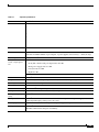
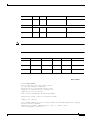
Table 1-1
Physical Specifications
Specification
•
•
•
controller, maximum number of port adapters, 2 power supplies, and a fan tray: ~ 50 lb (22.7 kg)
Heat dissipation
370W (1262 BTU2)
Chassis fan noise
levels—single speed
fan
Tested:
Front (I/O controller and port adapter side) 44.2 dB
Back (power supply side) 43.7 dB
Left (fan side) 47.2 dB
Right 44.8 dB
Maximum: 65 dBa
Airflow
~80 cfm3
Temperature
32 to 104°F (0 to 40°C) operating; –4 to 149°F (–20 to 65°C) nonoperating
Humidity
10 to 90% noncondensing
Power Specifications
4
wide input with power factor correction
5
AC-input current rating 5A at 100–240 VAC with the chassis fully configured
AC-input frequency
rating
50/60 Hz6
AC-input cable
18 AWG7 three-wire cable, with a three-lead IEC-320 receptacle on the power supply end, and a
country-dependent plug on the power source end
DC-output power
280W maximum (with either a single or dual power supply configuration)
DC-input voltage rating –48 VDC8 nominal in North America
–60 VDC nominal in the European Community
1-3
Software Requirements
Physical Specifications (continued)
1. Mbps = megabits per second
2. BTU = British thermal units
3. cfm = cubic feet per minute
4. VAC = volts alternating current
5. A = amperes
6. Hz = hertz
7. AWG = American Wire Gauge
8. VDC = volts direct current
Note
Software Requirements
•
•
•
•
•
•
•
•
Cisco 7204VXR Overview
1-4
Cisco 7204VXR Overview
Note
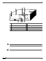
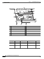
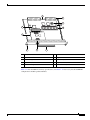
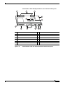
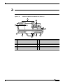
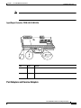
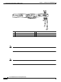
Figure 1-1
Cisco 7204VXR Router—Front View
1
Cisco 7200 SERIES XVR
FAST ETHERNET
4
K
RJ4
0
LIN
MII
5
D
LE
AB
EN
3
3
2
2
1
0
LINK
1
0
3
EN
AB
LE
D
ETHERNET 10BT
TX
2
RX
4
TX
3
O PW
K R
15889
1O
M
E II
N
R
E J4
N 5
R
L J4
IN 5
K
0
SL
O
T
EJ
EC
T
PC
M
C
IA
EN
AB
LE
D
0
R
J45
RX
RX
2
TX
R
ES
ET
FAST ETHERNET INPUT/OUTPUT CONTROLLER
C
PU
M
II
FE
1
SL
O
T
RX
1
TX
EN
RX
0
7
6
5
4
3
2
1
0
EN
1
2
TX
ETHERNET-10BFL
SERIAL-EIA/TIA-232
3
4
5
1
5
2
6
3
7
6
7
4
1-5
3
4
2
5
84396
1
NETWORK PROCESSING ENGINE-300
6
7
8
9
8
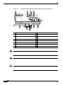
AC power cable-retention clip
5
1-6
9
PWR OK LED
Cisco 7206VXR Overview
Caution
Note
Cisco 7206VXR Overview
Note
1-7
Chapter 1
Cisco 7200 VXR Product Overview
Cisco 7206VXR Overview
Note
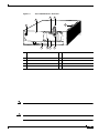
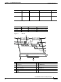
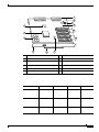
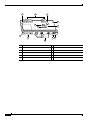
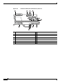
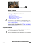
Figure 1-3
Cisco 7206VXR Router—Front View
2
1
3
2
1
0
6
TOKEN RING
5
FAST ETHERNET
4
RJ4
5
LIN
K
MII
0
2
TX
RX
4
TX
RX
3
TX
RX
2
TX
RX
1
R
ES
ET
0
R
J45
C
PU
M
II
FE
1
SL
O
T
FAST ETHERNET INPUT/OUTPUT CONTROLLER
O PW
K R
84517
1O
R
E J4
N 5
R
L J4
IN 5
K
M
E II
N
0
SL
O
T
PC
M
C
IA
EJ
EC
T
EN
AB
LE
D
Cisco 7200
Series VXR
TX
EN
0
RX
CD
LB
RC
RD
TC
TD
CD
LB
RC
RD
TC
TD
CD
LB
RC
RD
TC
TD
CD
LB
EN
RC
RD
TC
TD
1
4
D
ETHERNET-10BFL
FAST SERIAL
3
LE
AB
EN
3
3
2
2
1
0
LINK
1
0
3
EN
AB
LE
D
ETHERNET 10BT
5
6
7
8
Cisco 7200 VXR Installation and Configuration Guide
1-8
OL-5013-08
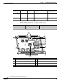
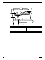
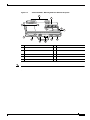
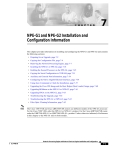
Figure 1-4
Cisco 7206VXR Router—Rear View
3
4
2
5
84396
1
NETWORK PROCESSING ENGINE-300
6
7
8
9
1-9
Field-Replaceable Units
Caution
Note
Field-Replaceable Units
•
•
•
•
•
•
•
1-10
Chapter 1
Cisco 7200 VXR Product Overview
Field-Replaceable Units
•
•
Note
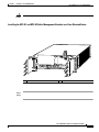
280-Watt AC-Input Power Supply Replacement Instructions
.
Network Processing Engine or Network Services Engine
Note
Network Processing Engine and Network Services Engine Installation
and Configuration
–
–
a BCM 1250 microprocessor that operates at an internal clock speed of 700 MHz.
–
–
–
–
Cisco 7200 VXR Installation and Configuration Guide
OL-5013-08
–
–
–
–
–
–
–
–
–
–
–
–
–
–
–
–
1-12
–
–
–
–
–
–
–
–
–
–
–
1-13
1-14
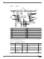
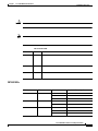
Figure 1-5
NPE-G2
1
10
9
2
8
4
3
5
7
149061
6
10
Table 1-2
NPE-G2 Memory Specifications
Memory Type
Size
Quantity
Description
Component Location
on the NPE-G2 Board
1-15
Chapter 1
Cisco 7200 VXR Product Overview
Field-Replaceable Units
Memory Type
Size
Quantity
Component Location
on the NPE-G2 Board
Description
NPE-G2 SDRAM Configuration—Configurable Memory Only
Total SDRAM
SDRAM Bank
Quantity
1
5
2
6
7
8
9
10
3
GIGABIT ETHERNET 0/1
LINK
EN
GBIC
TX
EN
RJ45
NETWORK PROCESSING ENGINE - G1
GIGABIT ETHERNET 0/1
LINK
RX
LINK
RX
GBIC
EN
TX
RJ45
SLOT
ACTIVE
CPU
RESET
RX
GBIC
TX
C O M PA C T F L A S H
POWER
ON
CONSOLE
AUX
66435
GIGABIT ETHERNET 0/1
RJ45
4
1
6
2
7
3
8
4
9
5
10
Cisco 7200 VXR Installation and Configuration Guide
OL-5013-08
Chapter 1
Cisco 7200 VXR Product Overview
Field-Replaceable Units
Memory Type
Size
Quantity
Description
Component Location
on the NPE-G1
Board
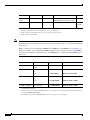
NPE-G1 SDRAM SODIMM Memory Configurations—Configurable Memory Only
Total SDRAM
SDRAM Bank
Quantity
Product Number
Cisco 7200 VXR Installation and Configuration Guide
OL-5013-08
Chapter 1
Cisco 7200 VXR Product Overview
Field-Replaceable Units
1
8
2
10
3
9
11
12
4
NETWORK PROCESSING ENGINE-200
5
6
66418
13
7
1
8
2
9
3
10
4
11
5
12
6
13
7
Memory Type
Size
Quantity
Description
Location1
Cisco 7200 VXR Installation and Configuration Guide
OL-5013-08
Chapter 1
Cisco 7200 VXR Product Overview
Field-Replaceable Units
Location on processing engine board. See Figure 1-7.
128 MB
U15
1 128-MB DIMM
MEM-SD-NPE-128MB=
256 MB
U15
1 256-MB DIMM
MEM-SD-NSE-256MB=
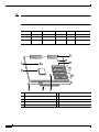
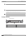
Figure 1-8
NPE-400
1
7
2
3
8
4
9
10
NETWORK PROCESSING ENGINE-400
5
66411
11
6
Temperature sensor (U31)
Midplane connector
Keying post
Boot ROM (U7)
RM7000 microprocessor
Temperature sensor
System controller
SODIMM (J1)
Captive installation screw
Standoff and screw
Handle
Cisco 7200 VXR Installation and Configuration Guide
OL-5013-08
Table 1-8 lists the NPE-400 memory specifications, and Table 1-9 lists factory-installed SDRAM
configurations and their product numbers.
SDRAM-configurable 128, 256, or
512 MB
1
128-, 256-, or 512-MB
SODIMM
J1
Boot ROM
512 KB
1
OTP1 ROM for the ROM
monitor program
U7
Primary cache
16 KB
(instruction),
16 KB (data)
—
RM7000 processor,
integrated cache
U38
Secondary cache
256 KB (fixed)
—
RM7000 processor, unified, U38
internal cache
Tertiary cache
4 MB (fixed)
—
RM7000 processor, external U2, U26,
cache
U27, U28,
U37
1. OTP = one-time programmable
Table 1-9
NPE-400 SDRAM SODIMM Memory Configurations
128 MB
J1
1 128-MB SODIMM
MEM-NPE-400-128MB=
256 MB
J1
1 256-MB SODIMM
MEM-NPE-400-256MB=
512 MB
J1
1 512 MB SODIMM
MEM-NPE-400-512MB=
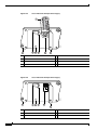
Figure 1-9
NPE-300
1
2
11
12
13
3
4
14
15
5
NETWORK PROCESSING ENGINE-300
6
7
8
66410
16
9 10
Midplane connectors
RM7000 microprocessor
Keying post
Temperature sensor (U42)
DIMM 3 (U44)
Keying post
Bank 1 (user configurable)
Temperature sensor
DIMM 2 (U45)
Boot ROM (U1)
Captive installation screw
DIMM 0 (U16)
Handle
Bank 0 (fixed size)
System controllers
U15 never populated
Table 1-10 lists the NPE-300 memory specifications, and Table 1-11 lists factory-installed SDRAM
configurations and their product numbers.
Table 1-10
NPE-300 Memory Specifications
SDRAM
32 to 256 MB
1 configurable2 32-, 64-, or 128-MB DIMMs
bank with 2
(based on maximum SDRAM
SDRAM slots
required)
Boot ROM
512 KB
1
OTP4 ROM for the ROM monitor
program
—
RM7000 processor, internal cache U49
Primary cache 16 KB
(instruction),
16 KB (data)
Bank 1:
U45 and
U443
Socket
U1
Secondary
cache
256 KB
—
RM7000 processor, internal,
unified instruction and data cache
U49
Tertiary cache
2 MB (fixed)
—
RM7000 processor, external cache U7, U8,
U9, U10,
U17
1. Location on processing engine board. See Figure 1-9.
2. Bank 0 is used exclusively for packet memory and is not user configurable.
3. Bank 1 contains the Cisco IOS software, processor memory, and packet memory.
4. OTP = one-time programmable
The NPE-300 contains two banks of SDRAM. Both SDRAM banks are used for all packet memory
requirements; however, bank 0 is used exclusively for packet memory and is set at a fixed configuration
in the factory.
Bank 1 contains two user-configurable SDRAM slots, DIMM slot 2 and DIMM slot 3 (see Figure 1-9).
Both slots in bank 1 can be populated by DIMMs of different sizes; however, the size of the DIMM in
slot 2 must be greater than or equal to the size of the DIMM in slot 3, and the size of the DIMM in slot 3
can be zero.
2
323 MB + 32 MB
U45 (DIMM slot 2
only)
1 32-MB DIMM
MEM-SD-NPE-32MB=
323 MB + 64 MB
U45 and U44
or
2 32-MB DIMMs
or
MEM-SD-NPE-32MB=
U45
1 64-MB DIMM
MEM-SD-NPE-64MB=
U45 and U44
or
2 64-MB DIMMs
or
MEM-SD-NPE-64MB=
U45
1 128-MB DIMM
MEM-SD-NPE-128MB=
U45 and U44
2 128-MB DIMMs
MEM-SD-NPE-128MB=
3
32 MB + 128 MB
323 MB + 256 MB
1. There are two user-upgradable SDRAM slots in bank 1. (Bank 0 is used exclusively for packet memory and is set at a fixed
configuration in the factory.)
2. These products are also available as SDRAM upgrades. To order an upgrade, add an equal sign (=) after the product number,
for example, MEM-SD-NPE-128MB=.
3. This 32 MB is fixed memory in SDRAM bank 0, socket U16. Socket U15 is never populated.
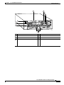
1
7
8
9
2
10
NETWORK PROCESSING ENGINE-200
4
5
66417
3
6
Network controller board
Handle
System controller
Midplane connectors
Processor engine board
Boot ROM (U1)
Captive installation screw
Temperature sensor
RM5271 microprocessor
SDRAM DIMM (U15)
Table 1-12 lists the NPE-225 memory specifications, and Table 1-13 lists factory-installed SDRAM
configurations and their product numbers.
7
8
9
10
1
U52
11
U42
2
U25
12
3
NETWORK PROCESSING ENGINE-200
4
5
6
66420
U11
1
7
8
9
2
10
NETWORK PROCESSING ENGINE-150
4
5
6
66416
3
7
8
9
1
U12
10
U4
2
U25
11
3
NETWORK PROCESSING ENGINE-150
4
5
6
66424
U18
6
7
8
1
U12
9
U4
2
U25
10
NETWORK PROCESSING ENGINE-100
3
4
5
66433
U18
show version
Router# show version
Cisco Internetwork Operating System Software
IOS (tm) 7200 Software (C7200-JS-M),
Released Version 12.2(20011220:181136) [biff]
Copyright (c) 1986-2001 by cisco Systems, Inc.
Compiled Fri 21-Dec-01 05:58 by
Image text-base:0x600089B8, data-base:0x6196E000
ROM:System Bootstrap, Version 12.2(20011219:132854)
(display text omitted)
cisco 7206VXR (NPE-G1) processor (revision 0x00) with 245760K/16384K bytes of memory.
Processor board ID 13250983
BCM12500 CPU at 500Mhz, Implementation 1, Rev 0.1, 512KB L2 Cache
6 slot VXR midplane, Version 2.0
Input/Output Controller
Note
Input/Output Controller Replacement Instructions
I/O Controller Descriptions
1 Fast Ethernet port; equipped with an MII receptacle and an RJ-45 receptacle
for use at 100 Mbps full-duplex or half-duplex operation. Only 1 receptacle
can be configured for use at a time. (See Figure 1-17.)
C7200-I/O
C7200-I/O-FE-MII
Has no Fast Ethernet port. (See Figure 1-19.)
2
1 Fast Ethernet port; equipped with a single MII receptacle. (See Figure 1-21.)
The Product Number C7200-I/O-FE does not specify MII because both an MII and an RJ-45 receptacle are included.
2. The I/O controller with the Product Number C7200-I/O-FE-MII has a single MII Fast Ethernet receptacle only. Although still
supported by Cisco Systems, this I/O controller with a single MII receptacle is no longer an orderable product as of May 1998.
show diag slot 0
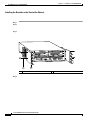
C7200-I/O-GE+E—With GBIC Gigabit Ethernet and RJ-45 Ethernet Receptacles
1
3
2
6
4
7
5
1
SL
D
LE
AB
PC
MC
T
IA
EC
EJ
OT
SL
0
RT
RX PO E O
G
TX
K
D
1
E L
E
LIN
L E
S
1 TD
A
T
L
C E N
C
U S A
E
D AS Y
D
O L O
D
R K V
E
P IT EC
L
D
VE1
O
E M
T
L T AS
C
1 K IT S
U
S U U LA
D
S D D
O
A O O C
R
L R R E
P
C P P D
K
ETHERNET GIGABIT ETHERNET INPUT/OUTPUT CONTROLLER
LIN
RT 0
PO E
R
PW
IO K
O
U
CP ET
S
RE
AU
X
CO
NS
OL
E
84526
OT
C7200-I/O-GE+E
EN
8
9
Figure 1-16
10
11
12 13
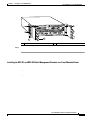
C7200-I/O-2FE/E—With Two RJ-45 Ethernet/Fast Ethernet Receptacles
1
3
2
6
4
7
5
1
LIN
SL
K
LIN
K
DUAL FAST ETHERNET INPUT/OUTPUT CONTROLLER
D
LE
AB
PC
T
EC
IA
MC
EJ
SL
OT
s
0
bp
0
10
M
F
E/E
s
bp
0
0
10
M
F
E/E
1
R
PW
IO K
O
U
CP ET
S
RE
AU
X
CO
NS
OL
E
8
9
11 12
10
84525
OT
C7200-I/O-2FE/E
EN
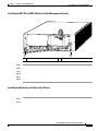
Figure 1-17
C7200-I/O-FE—With MII and RJ-45 Fast Ethernet Receptacles (Version 1)
2
3
1
5
4
N
A
B
LE
LO
T
1
FE
M
II
R
5
J4
N
E
R
FAST ETHERNET INPUT/OUTPUT CONTROLLER
5
J4 K
LIN
D
C
T
T
C
IA
JE
C
M
E
C
P
LO
0
M
S
II
E
N
R
J4
5
I/O
P
U
R
W
P OK
R
E
S
E
T
A
U
X
C
O
N
S
O
LE
7
8
12
9
11
10
13
84531
S
E
6
Figure 1-18
C7200-I/O-FE—With MII and RJ-45 Fast Ethernet Receptacles (Version 2)
1
2
3
4
5
7
8
6
1
FE
M
II
R
5
J4
N
E
R
FAST ETHERNET INPUT/OUTPUT CONTROLLER
5
J4 K
LIN
C
P
U
T
T
C
IA
C
M
C
P
JE
E
LO
0
M
II
E
S
N
R
J4
5
R
W
P OK
O
R
E
S
E
T
A
U
X
I/
C
O
N
S
O
LE
9
10
14
11
13
12
15
84523
T
LO
S
D
LE
B
A
N
E
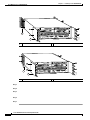
Figure 1-19
C7200-I/O—Without Fast Ethernet Port (Version 1)
2
3
1
5
4
A
N
T
1
FAST ETHERNET INPUT/OUTPUT CONTROLLER
D
LE
B
C
P
M
C
C
JE
E
IA
T
T
LO
S
0
C
U
P
R
E
E
S
T
P
W
R
O
K
A
X
U
IO
C
O
S
N
O
LE
7
8
10
9
11
93277
LO
S
E
6
Figure 1-20
C7200-I/O—Without Fast Ethernet Port (Version 2)
1
2
3
4
5
7
8
6
1
INPUT/OUTPUT CONTROLLER
C
P
U
T
T
C
IA
C
M
C
P
JE
E
LO
S
0
R
W
P OK
I/O
R
E
S
E
T
A
U
X
C
O
N
S
O
LE
9
10
13
12
11
14
84524
T
LO
S
D
LE
B
A
N
E
Figure 1-21
C7200-I/O-FE-MII—With Single MII Fast Ethernet Receptacle
2
3
1
5
4
LO
T
1
FE
M
FAST ETHERNET INPUT/OUTPUT CONTROLLER
II
D
LE
B
A
N
E
LE
T
T
C
IA
JE
C
M
E
C
P
N
LO
E
S
F
E
T
K
B
A
0
E
LIN
F
U
P
C
E
E
S
R
R
W
P
O
K
A
U
X
IO
C
O
N
S
O
LE
7
8
11
9
10
12
84534
S
6
Type
Flash memory
Size
Quantity
Memory Description
Model
Location
256 KB
1
32-pin DIP-type
C7200-I/O-FE-MII
U20
32-pin DIP-type or
32-pin PLCC-type
C7200-I/O-FE,
C7200-I/O
U20 or U4
Contains the default
boot helper image
C7200-I/O-FE-MII
U99
C7200-I/O-FE,
C7200-I/O
U99
or
4 MB
1
U10, U11,
U12, and U13
(soldered)2
8 MB
1
Flash memory
card
16 or
20 MB
Up to 2
Flash Disk
32, 48, or
128 MB
Up to 2
NVRAM
128 KB
1
C7200-I/O-GE+E,
C7200-I/O-2FE/E
U13 and U25
(soldered)2
Contains the default
Cisco IOS image
All models
PC Card slot 0
and slot 1
Nonvolatile EPROM
for the system
configuration file
C7200-I/O-FE-MII
U41
C7200-I/O-FE,
C7200-I/O
U41
or
U14
(soldered)3
C7200-I/O-GE+E,
C7200-I/O-2FE/E
U19
(soldered)3
The C7200-I/O-GE+E and C7200-I/O-2FE/E do not have a boot ROM component.
2. Some I/O controllers have no Flash SIMM but use a permanently soldered 4-MB or 8-MB Flash memory chip instead. (For
the location of the 4-MB Flash memory chip, see the Figure 1-18 and Figure 1-20. For the location of the 8-MB Flash memory
chip, see Figure 1-15 and Figure 1-16.)
3. The NVRAM on some I/O controllers is replaced by a 32-pin nonsocketed SRAM component that is soldered onto the card.
The SRAM component is made to act like the NVRAM by the addition of some external components, one of which is a 1-inch
(2.54-cm) button-type lithium battery.
LED Descriptions
Chapter 1
Cisco 7200 VXR Product Overview
Field-Replaceable Units
Caution
Note
I/O Controller LEDs
LED
Color
Function
NPE-G2 LEDs
LED Label
LED
Color
Status in the Power Up State
Cisco 7200 VXR Installation and Configuration Guide
OL-5013-08
Chapter 1
Cisco 7200 VXR Product Overview
Field-Replaceable Units
LED Label
LED
Color
Status in the Power Up State
NPE-G1 LEDs
LED Label
LED
Color
LINK, 0/1, 0/2,
0/3
RJ-45 and
GBIC ports
Green
EN (Enable),
0/1, 0/2, 0/3
RJ-45 ports
only
Green
LED Status in the Power Up State
LED Flashes when
There Is Traffic
No
SLOT ACTIVE CompactFlash
Disk
Green
On when the slot is being used.
POWER ON
Green
On and stays on.
Cisco 7200 VXR Installation and Configuration Guide
OL-5013-08
Chapter 1
Cisco 7200 VXR Product Overview
Field-Replaceable Units
Input/Output Controller C7200-I/O LEDs
C7200-I/O LEDs and CPU Reset Button
LO
T
1
INPUT/OUTPUT CONTROLLER
P
C
M
C
IA
E
S
JE
C
T
S
LO
T
LO
T
0
P
IO
E
W
O
K
O
R
C
P
U
R
E
S
E
T
A
U
X
C
O
N
S
O
LE
H7401
S
D
LE
B
A
N
E
1
D
LE
T
R
T
0
LO
IO
S
S
LO
T
E
W
O K
O
E
S
E
P
U
R
P
C
1
C
P
U
R
E
S
E
INPUT/OUTPUT CONTROLLER
T
D
LE
B
A
N
E
T
T
C
IA
JE
C
M
LO
E
C
P
0
S
T
R
A
W
P
K
I/O O
U
X
C
O
N
1
S
O
LE
25930
AB
EN
T
E
LO
S
E
S
U
R
P
C
D
E
BL
A
EN
T
0
LO
S
R
W
P
K
I/O O
Input/Output Controller C7200-I/O-GE+E LEDs
Cisco 7200 VXR Installation and Configuration Guide
OL-5013-08
Chapter 1
Cisco 7200 VXR Product Overview
Field-Replaceable Units
1
SL
D
LE
AB
PC
IA
MC
T
EC
OT
RT 0
RX POGE
0
SL
EJ
OT
TX
K
K
D
1
E L
E
LIN
L E
S
1 TD
A
T
L
C E N
C
U S A
E
D AS Y
D
O L O
D
R K V
E
P IT EC
L
D
VE1
O
E M
T
L T AS
C
1 K IT S
U
S U U LA
D
S D D
O
A O O C
R
L PRPR E
P
D
C
ETHERNET GIGABIT ETHERNET INPUT/OUTPUT CONTROLLER
LIN
R
PW
IO K
O
U
CP ET
S
RE
RT 0
PO E
AU
X
CO
NS
OL
E
33446
OT
C7200-I/O-GE+E
EN
1
SL
IC
GBN
E
D
LE
AB
NK
LI
R
PW
IO K
O
U
CP ET
S
RE
NK
LI
EN
0
OT
SL
LED
Color
Function
Input/Output Controller C7200-I/O-2FE/E LEDs
1
K
K
LIN
SL
DUAL FAST ETHERNET INPUT/OUTPUT CONTROLLER
LIN
D
LE
AB
PC
MC
T
IA
OT
EC
s
0
bp
SL
EJ
0
10
OT
M
/E
s
bp
0
FE
0
10
R
PW
IO K
O
U
CP ET
S
RE
AU
X
CO
NS
OL
E
NK
L
EN
s
0
SL
1
LI
ED
OT
FE
1
SL
AB
/E
M
33444
OT
C7200-I/O-2FE/E
EN
bp
0
10
M
R
PW
IO K
O
U
CP ET
S
RE
Cisco 7200 VXR Installation and Configuration Guide
OL-5013-08
Chapter 1
Cisco 7200 VXR Product Overview
Field-Replaceable Units
LED
Color
Function
Note
Input/Output Controller C7200-I/O-FE LEDs
Cisco 7200 VXR Installation and Configuration Guide
OL-5013-08
Chapter 1
Cisco 7200 VXR Product Overview
R
J-4
5
D
C
LE
P
U
R
E
S
E
T
FAST ETHERNET INPUT/OUTPUT CONTROLLER
B
A
N
E
R
5
J4
N
E
R
5
J4 K
LIN
R
W
P
IO OK
SL
O
T
1
II
M
N
E
H11294
Field-Replaceable Units
ED
T
E
S
BL
E
A
EN
5
J4
R N
E
5
J4
R INK
L
U
R
P
R
W
P K
IO O
C
SL
O
T
0
II
M N
E
1
II
FE
M
R
5
J4
N
E
R
FAST ETHERNET INPUT/OUTPUT CONTROLLER
5
J4 K
LIN
C
P
U
R
E
S
E
T
T
T
C
IA
JE
C
M
E
C
P
0
M
LO
E
N
R
J4
OT
5
I/O
R
W
P OK
A
U
X
C
1
N
S
O
LE
T
E
S
E
AB
U
EN
R
P
C
OT
0
SL
LED
O
5
J4
R INK
L
5
J4
R N
E
SL
D
LE
II
S
25929
T
LO
S
D
LE
B
A
N
E
Color
II
N
E
M
I/O
R
W
P OK
Function
Cisco 7200 VXR Installation and Configuration Guide
OL-5013-08
Chapter 1
Cisco 7200 VXR Product Overview
Field-Replaceable Units
Note
FAST ETHERNET INPUT/OUTPUT CONTROLLER
D
LE
B
A
N
SL
O
T
1
E
H6523
Input/Output Controller C7200-I/O-FE-MII LEDs
D
LE
EN F
A E
FE BL
E
LI
N
C
K
PU
R
IO
ES
PO
ET
W
ER
O
K
AB
SL
O
T
0
EN
LED
Color
Function
Port Adapters and Service Adapters
Cisco 7200 VXR Installation and Configuration Guide
OL-5013-08
Chapter 1
Cisco 7200 VXR Product Overview
Field-Replaceable Units
Note
Note
PA-4E Ethernet 10BaseT Port Adapter Installation and Configuration
Port Adapter Jacket Card
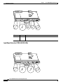
Port Adapter Jacket Card
1
1
2
4
3
4
5
138883
PW
R
EN
AB
LE
D
PORT ADAPTER JACKET CARD
Cisco 7200 VXR Installation and Configuration Guide
OL-5013-08
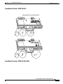
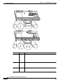
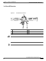
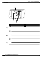
Figure 1-28
Cisco 7200 Series AC-Input Power Supply
84397
7
1
3
4
5
6
Cisco 7200 Series DC-Input Power Supply
89372
Figure 1-29
2
1
2
3
4
5
6
6
5
4
3
2
1
14628
0
Cisco 7200
Series VXR
CompactFlash Disks, Flash Disks, and PC Cards
Note
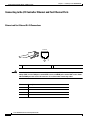
Using
Note
the Flash Disk
Memory Replacement Instructions for the Network Processing Engine or Network Services Engine and
Input/Output Controller
Network Processing Engine or Network Services Engine Installation
and Configuration
Memory Size
Product Number1
Memory Size
Product Number1
Memory Size
Product Number
Rack-Mount and Cable-Management Kit
Chapter 1
Cisco 7200 VXR Product Overview
Functional Overview
Functional Overview
Chassis Slot and Logical Interface Numbering
2
3
6
1
5
Cisco 7200 SERIES
4
RJ4
5
LIN
K
EN
MII
AB
LE
D
FAST ETHERNET
0
3
4
2
TX
RX
4
TX
3
RX
RX
2
TX
RX
1
TX
EN
RX
1
0
7
6
5
4
3
2
1
0
EN
TX
ETHERNET-10BFL
SERIAL-EIA/TIA-232
R
ES
ET
O PW
K R
84540
1O
M
E II
N
R
E J4
N 5
R
L J4
IN 5
K
0
SL
O
T
EJ
EC
T
PC
M
C
IA
EN
AB
LE
D
0
R
J45
FAST ETHERNET INPUT/OUTPUT CONTROLLER
C
PU
M
II
FE
SL
O
T
1
5
6
1
4
2
5
3
6
Cisco 7200 VXR Installation and Configuration Guide
OL-5013-08
Chapter 1
Cisco 7200 VXR Product Overview
Functional Overview
1
2
3
4
4
K
RJ4
0
LIN
MII
5
D
LE
AB
EN
2
TX
RX
4
TX
RX
3
TX
RX
2
RX
1
ES
ET
FAST ETHERNET INPUT/OUTPUT CONTROLLER
O PW
K R
84518
R
E J4
N 5
1O
R
L J4
IN 5
K
M
E II
N
0
SL
O
T
EJ
EC
T
PC
M
C
IA
EN
AB
LE
D
0
R
J45
C
PU
R
M
II
FE
1
SL
O
T
TX
EN
0
RX
CD
LB
RC
RD
TC
TD
CD
LB
RC
RD
TC
TD
CD
LB
RC
RD
TC
TD
CD
LB
EN
RC
RD
TC
TD
1
Cisco 7200
Series VXR
TX
3
2
3
LINK
1
0
2
1
D
0
LE
AB
EN
3
ETHERNET-10BFL
FAST SERIAL
7
3
FAST ETHERNET
ETHERNET 10BT
6
2
1
0
5
5
6
TOKEN RING
8
1
5
2
6
3
7
4
8
Cisco 7200 VXR Installation and Configuration Guide
OL-5013-08
Chapter 1
Cisco 7200 VXR Product Overview
Functional Overview
show interfaces
Hardware is i82543 (Livengood), address is 0000.0000.0000 (bia 0000.0000.0000)
MTU 1500 bytes, BW 100000 Kbit, DLY 100 usec,
reliability 255/255, txload 1/255, rxload 1/255
(display text omitted)
FastEthernet0/1 is administratively down, line protocol is down
Hardware is i82543 (Livengood), address is 0000.0000.0000 (bia 0000.0000.0000)
MTU 1500 bytes, BW 100000 Kbit, DLY 100 usec,
reliability 255/255, txload 1/255, rxload 1/255
(display text omitted)
GigabitEthernet0/1 is up, line protocol is up
Hardware is BCM-12500 Internal MAC, address is 0000.0000.0000 (bia 0000.0000.0000)
Internet address is 00.00.00.00/00
MTU 1500 bytes, BW 1000000 Kbit, DLY 10 usec,
reliability 255/255, txload 2/255, rxload 2/255
(display text omitted)
GigabitEthernet0/2 is up, line protocol is up
Hardware is BCM-12500 Internal MAC, address is 0000.0000.0000(bia 0000.0000.0000)
Internet address is 00.00.00.00/00
MTU 1500 bytes, BW 1000000 Kbit, DLY 10 usec,
reliability 255/255, txload 2/255, rxload 2/255
(display text omitted)
GigabitEthernet0/3 is administratively down, line protocol is down
Hardware is BCM-12500 Internal MAC, address is 0000.0000.0000 (bia 0000.0000.0000)
Internet address is 00.00.00.00/00
MTU 1500 bytes, BW 1000000 Kbit, DLY 10 usec,
reliability 255/255, txload 1/255, rxload 1/255
(display text omitted)
FastEthernet2/0 is administratively down, line protocol is down
Hardware is i82543 (Livengood), address is 0000.0000.0000 (bia 0000.0000.0000)
MTU 1500 bytes, BW 100000 Kbit, DLY 100 usec,
reliability 255/255, txload 1/255, rxload 1/255
(display text omitted)
FastEthernet2/1 is administratively down, line protocol is down
Hardware is i82543 (Livengood), address is 0000.0000.0000 (bia 0000.0000.0000)
MTU 1500 bytes, BW 100000 Kbit, DLY 100 usec,
reliability 255/255, txload 1/255, rxload 1/255
(display text omitted)
FastEthernet5/0 is up, line protocol is up
Hardware is DEC21140, address is 0000.0000.0000 (bia 0000.0000.0000)
Internet address is 00.00.00.00/00
MTU 1500 bytes, BW 100000 Kbit, DLY 100 usec,
reliability 255/255, txload 1/255, rxload 1/255
Cisco 7200 VXR Installation and Configuration Guide
OL-5013-08
Router# show interface fastethernet 5/0
1.
2.
3.
Chapter 1
Cisco 7200 VXR Product Overview
Functional Overview
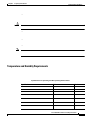
Environmental Monitoring and Reporting Functions
Environmental Monitoring
•
•
•
•
•
Cisco 7200 VXR Installation and Configuration Guide
OL-5013-08
Chapter 1
Cisco 7200 VXR Product Overview
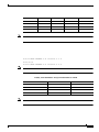
Functional Overview
NPE-G21
Low Warning
High Warning
Shutdown
NPE-G11
Low Warning
High Warning
Shutdown
Parameter
High Warning
High Critical
Shutdown
NPE-175, NPE-225, NPE-300,
NPE-400, NSE-1
NPE-100 or NPE-200
NPE-150
Cisco 7200 VXR Installation and Configuration Guide
OL-5013-08
00:00:44:%ENVM-4-ENVWARN:+3.45 V measured at +3.57
Router(boot)#
00:04:49:%ENVM-4-ENVWARN:+5.15 V measured at +5.33
12.0(23), Cisco IOS Release 12.3(8), and Later Releases of Each
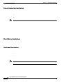
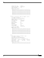
Reporting Functions
show environment show environment all show environment last,
table
show environment
show environment
show environment
show environment
show environment last
show environment
show environment last
show environment last
show environment table
show environment all
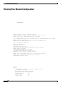
Power Supply 2 is Zytek AC Power Supply. Unit is on.
Temperature
chassis
chassis
chassis
chassis
readings:
inlet
measured
outlet 1 measured
outlet 2 measured
outlet 3 measured
Voltage readings:
+3.45 V
+5.15 V
+12.15 V
-11.95 V
measured
measured
measured
measured
at
at
at
at
at
at
at
at
26C/78F
28C/82F
29C/84F
33C/91F
+3.46 V
+5.25 V
+12.24 V
-11.81 V
Envm stats saved 138 time(s) since reload
Queued messages:
%ENVM-1-SHUTDOWN: Environmental Monitor initiated shutdown
C H A P T E R
2
Preparing for Installation
•
•
•
•
•
•
•
•
Warning
Before you install, operate, or service the system, read the “Site Preparation and Safety” section of the
Regulatory Compliance and Safety Information for the Cisco 7200 Series Routers. This guide contains
important safety information you should know before working with the system. Statement 200
2-1
Electrical Equipment Guidelines
•
•
•
•
•
•
•
•
•
•
•
•
Electrical Equipment Guidelines
Caution
Preventing Electrostatic Discharge Damage
Chapter 2
Preparing for Installation
Site Requirement Guidelines
Site Requirement Guidelines
Cisco 7200 VXR Installation and Configuration Guide
OL-5013-08
Chapter 2
Preparing for Installation
Site Requirement Guidelines
1
3
84535
2
4
1
3
2
4
•
•
•
•
Cisco 7200 VXR Installation and Configuration Guide
OL-5013-08
Chapter 2
Preparing for Installation
Site Requirement Guidelines
Rack-Mounting Guidelines
•
•
•
Cisco 7200 VXR Installation and Configuration Guide
OL-5013-08
Chapter 2
Preparing for Installation
Site Requirement Guidelines
1
2
3
4
84536
5
6
1
4
2
5
3
6
Cisco 7200 VXR Installation and Configuration Guide
OL-5013-08
Chapter 2
Preparing for Installation
Site Requirement Guidelines
•
Caution
•
•
•
Note
Temperature and Humidity Requirements
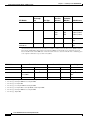
Specifications for Operating and Nonoperating Environments
Specification
Minimum
Maximum
Cisco 7200 VXR Installation and Configuration Guide
OL-5013-08
Chapter 2
Preparing for Installation
Site Requirement Guidelines
Power Connection Guidelines
•
•
Note
Plant Wiring Guidelines
Interference Considerations
•
•
Note
Cisco 7200 VXR Installation and Configuration Guide
OL-5013-08
Chapter 2
Preparing for Installation
Initial Configuration Information
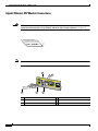
Distance Limitations and Interface Specifications
Note
•
•
•
•
•
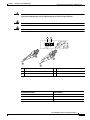
PA-A3
Enhanced ATM Port Adapter Installation and Configuration
Initial Configuration Information
Cisco 7200 VXR Installation and Configuration Guide
OL-5013-08
Chapter 2
Preparing for Installation
Cisco 7200 VXR Router Installation Checklist
•
•
•
•
•
•
Zone names, network numbers, or node numbers for the new interfaces if required
Operating speeds for specific interfaces—for example, Token Ring interfaces operate at either
4 or 16 Mbps, and serial interfaces operate at speeds of up to 2 Mbps. The speed of an interface
often depends on the speed of the remote device to which it is attached.
For complete configuration instructions, refer to the
and the
Documentation DVD.
, which are available on Cisco.com or on the
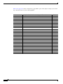
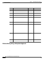
To assist you with your installation and to provide a historical record of what was done by whom, use
the Cisco 7200 VXR Router Installation Checklist in Table 2-2 on page 2-11. Make a copy of this
checklist and indicate when each procedure or verification is completed. When the checklist is
completed, place it in your site log (described at the end of this chapter) along with the other records for
your new router.
Cisco 7200 VXR Installation and Configuration Guide
OL-5013-08
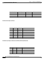
Date router received
Router and all accessories unpacked
Types and numbers of interfaces verified
Safety recommendations and guidelines reviewed
Installation Checklist copied
Site log established and background information entered
Site power voltages verified
Site environmental specifications verified
Required passwords, IP addresses, device names, and so on, available
Required tools available
Network connection equipment available
Router mounted in rack (optional)
Cable-management brackets installed (optional but recommended)
AC power cable(s) connected to AC source(s) and router; retention clip secured
DC power cable(s) connected to DC source(s) and router
Captive installation screws on I/O controller and network processing engine or network services
engine checked
Network interface cables and devices connected
ASCII terminal attached to console port
Console port set for 9600 baud, 8 data bits, no parity, and 2 stop bits (9600 8N2)
System power turned on (DC OK LED is on)
System boot complete (I/O controller enabled LED is on)
I/O controller, network processing engine or network services engine, and all port adapters
operational (enabled LEDs on the port adapters and the I/O controller are on)
Correct hardware configuration displayed after system banner appears
System ready for global and interface-specific configuration
Once you receive your Cisco 7200 VXR router, use the following procedure to check the contents of the
shipping container. Use the Cisco 7200 VXR Component List in Table 2-3 to ensure you received all the
components you ordered.
Do not discard the shipping container. You need the container if you move or ship the Cisco 7200 VXR
router in the future.
Verify that the following are included in the shipping container (the accessories box might be separate):
One Cisco 7200 VXR router, fully assembled (except the rack-mount and cable-management kit)
One or more accessories boxes (some or all may be shipped separately)
Check the contents of the accessories box against the Cisco 7200 VXR Component List and the packing
slip to verify that you received all listed equipment, which should include the following:
One modular power cable for each AC-input power supply
One rack-mount and cable-management kit (four brackets and 14 mounting screws)
Optional equipment that you ordered, such as network interface cables, transceivers, or special
connectors
Cisco 7200 VXR router hardware and software documentation, if ordered
We no longer ship the entire router documentation set automatically with each system. You must
specifically order the documentation as part of the sales order. If you ordered documentation and
did not receive it, we will ship the documents to you within 24 hours. To order documents,
contact a customer service representative.
Verify that the port adapters installed in your Cisco 7200 VXR router match the port adapter types on
the packing list.
Proceed to the “Site Log” section on page 2-13, and then to Chapter 3, “Installing a Cisco 7200 VXR
Router,” to begin the installation.
Received
•
•
•
Titles and quantities of documents will vary. You must order the type and quantity of documentation sets when you order the
hardware.
Site Log
A site log provides a historical record of all actions relevant to the Cisco 7200 VXR router operation and
maintenance. Keep your site log in a common place near the chassis where anyone who performs tasks
has access to it. Site log entries might include the following:
•
Installation progress—Make a copy of the Cisco 7200 VXR Router Installation Checklist and insert
it into the site log. Make entries on this checklist as each procedure is completed.
•
Upgrades, removal, and replacement procedures—Use the site log as a record of system
maintenance and expansion history. Each time a procedure is performed on the system, update the
site log to reflect the following:
–
–
–
–
–
–
–
–
–
–
Table 2-4 on page 2-14 shows a sample site log page. Make copies of the sample or design your own site
log to meet the needs of your site and equipment.
Description of Action Performed or Symptom Observed
Initials
3
Installing a Cisco 7200 VXR Router
•
•
•
•
•
•
•
Note
Caution
Warning
Before you install, operate, or service the system, read the “Site Preparation and Safety”
. This guide contains
important safety information you should know before working with the system.
Cisco 7200 VXR Installation and Configuration Guide
OL-5013-08
Chapter 3
Installing a Cisco 7200 VXR Router
Rack-Mounting a Cisco 7200 VXR Router
Rack-Mounting a Cisco 7200 VXR Router
Cisco 7200 VXR Installation and Configuration Guide
OL-5013-08
Typical Four-Post Equipment Rack Posts and Mounting Strips
1
3
4
5
84516
2
R
LI J4
N 5
K
R
E J4
N 5
1O
0
CP
U
RJ
-4
5
FE
1
RE
SE
T
M
II
SL
O
T
4
3
2
1
0
2
TX
RX
TX
RX
TX
RX
TX
RX
TX
RX
CD
LB
RC
RD
TC
TD
CD
LB
RC
EN
EN
RD
TC
TD
CD
LB
RC
RD
TC
TD
CD
LB
RC
RD
TC
TD
0
3
D
LIN
K
3
2
1
0
LE
4
RJ4
5
LI
NK
MII
EN
AB
LE
D
1
2
AB
0
EN
3
ETHERNET 10BT
84519
0
1
FAST SERIAL
M
E II
N
SL
O
T
EJE
C
T
PC
M
C
IA
Cisco 7200
XVR eries
EN
AB
LE
D
5
6
3
2
1
0
Figure 3-2
Installing the Chassis in a Four-Post Rack—Front Installation Shown
FAST ETHERNET
ETHERNET-10BFL
R
W
P K
O
FAST ETHERNET INPUT/OUTPUT CONTROLLER
1
1
84520
0
5
1O
O PW
K R
R
L J4
IN
K
C
PU
R
J45
R
ES
ET
M
II
1
4
3
2
1
0
EN
2
TX
RX
TX
RX
TX
RX
TX
RX
TX
RX
CD
LB
RC
RD
TC
TD
CD
LB
RC
RD
TC
TD
EN
0
3
D
4
RJ4
5
LIN
K
MII
BLE
LINK
3
2
1
0
LE
EN
A
1
2
AB
0
EN
3
D
ETHERNET 10BT
R
E J4
N 5
FE
SL
O
T
CD
LB
RC
RD
TC
TD
CD
LB
RC
RD
TC
TD
FAST SERIAL
M
E II
N
SL
O
T
EJ
EC
T
PC
M
C
IA
Cisco 7200
Series VXR
EN
AB
LE
D
1
5
6
3
2
1
0
TOKEN RING
FAST ETHERNET
ETHERNET-10BFL
FAST ETHERNET INPUT/OUTPUT CONTROLLER
2
84548
0
R
E J4
N 5
O PW
K R
1O
0
C
PU
R
J45
R
ES
ET
II
M
1
4
3
2
1
0
EN
2
TX
RX
TX
RX
TX
RX
TX
RX
TX
RX
CD
LB
RC
RD
TC
TD
CD
LB
RC
RD
TC
TD
EN
0
3
D
LE
4
RJ4
5
LIN
K
MII
AB
LINK
3
2
1
0
LE
EN
1
2
AB
0
EN
D
ETHERNET 10BT
R
L J4
IN 5
K
FE
T
O
SL
CD
LB
RC
RD
TC
TD
CD
LB
RC
RD
FAST SERIAL
M
E II
N
SL
O
T
EJ
EC
T
PC
M
C
IA
1
1
TC
3
TD
5
Cisco 7200
Series
EN
AB
LE
D
6
3
2
1
0
TOKEN RING
FAST ETHERNET
ETHERNET-10BFL
FAST ETHERNET INPUT/OUTPUT CONTROLLER
84547
0
O PW
K R
1O
R
LI J4
N 5
K
0
U
5
-4
CP
RJ
FE
RE
SE
T
1
M
II
SLO
T
4
3
2
1
0
2
TX
RX
TX
RX
TX
RX
TX
RX
TX
RX
CD
LB
RC
RD
TC
TD
CD
LB
RC
EN
EN
RD
TC
TD
CD
LB
RC
RD
TC
TD
CD
LB
RC
RD
0
3
2
3
2
NK
LE
4
RJ4
5
LI
MII
AB
LIN
K
EN
1
0
D
1
0
EN
AB
LE
D
ETHERNET 10BT
R
E J4
N 5
M
E II
N
SLO
T
EJE
C
T
PC
M
C
IA
1
1
TC
TD
3
Cisco 7200
Series
EN
AB
LE
D
5
FAST SERIAL
FAST ETHERNET
6
3
2
1
0
TOKEN RING
ETHERNET-10BFL
FAST ETHERNET INPUT/OUTPUT CONTROLLER
1
2
2
Attaching the Chassis Rack-Mount and Cable-Management Brackets
Chapter 3
Installing a Cisco 7200 VXR Router
Rack-Mounting a Cisco 7200 VXR Router
Installing the Brackets on the Front of the Chassis
Step 1
Step 2
Step 3
3
2
1
0
6
TOKEN RING
5
4
NK
LI
MII
0
2
TX
RX
4
TX
RX
3
TX
2
RX
TX
RX
ET
FAST ETHERNET INPUT/OUTPUT CONTROLLER
84521
O PW
K R
1O
R
L J4
IN 5
K
R
E J4
N 5
M
E II
N
0
SL
O
T
EJE
C
T
PC
M
C
IA
EN
AB
LE
D
0
R
C
J-
45
PU
R
ES
M
II
FE
SL
O
T
1
1
0
1
TX
CD
EN
ETHERNET-10BFL
RX
LB
RC
RD
TC
TD
CD
LB
RC
RD
TC
TD
CD
LB
RC
RD
TC
TD
CD
LB
EN
RC
RD
TC
TD
EN
AB
LE
D
K
3
3
2
LIN
1
0
2
D
1
0
LE
AB
EN
3
FAST SERIAL
Cisco 7200
Series VXR
RJ4
5
FAST ETHERNET
ETHERNET 10BT
1
2
1
2
Step 4
Cisco 7200 VXR Installation and Configuration Guide
OL-5013-08
Chapter 3
Installing a Cisco 7200 VXR Router
Rack-Mounting a Cisco 7200 VXR Router
3
2
1
0
6
TOKEN RING
5
4
RJ4
5
MII
0
2
TX
RX
4
TX
3
RX
TX
2
SE
5
-4
0
CP
RJ
U
RE
M
II
RX
TX
RX
1
0
T
FAST ETHERNET INPUT/OUTPUT CONTROLLER
84545
O PW
K R
1O
R
LI J4
N 5
K
R
E J4
N 5
M
E II
N
0
SL
O
T
EJE
C
T
EN
AB
LE
D
PC
M
C
IA
1
FE
SL
O
T
1
1
1
TX
CD
EN
ETHERNET-10BFL
RX
LB
RC
RD
TC
TD
CD
LB
RC
RD
TC
TD
CD
LB
RC
RD
TC
TD
CD
EN
LB
RC
RD
TC
TD
EN
AB
LE
D
K
3
3
2
LIN
1
0
2
D
1
0
LE
AB
EN
3
FAST SERIAL
Cisco 7200
Series
LI
NK
FAST ETHERNET
ETHERNET 10BT
2
2
Step 5
Installing the NPE-G1 and NPE-G2 Cable-Management Brackets on a Front-Mounted Router
•
•
Cisco 7200 VXR Installation and Configuration Guide
OL-5013-08
Chapter 3
Installing a Cisco 7200 VXR Router
H6423
Rack-Mounting a Cisco 7200 VXR Router
1
1
GIGABIT ETHERNET 0/1
GIGABIT ETHERNET 0/1
LINK
GIGABIT ETHERNET 0/1
LINK
NETWORK PROCESSING ENGINE - G1
LINK
CPU
RESET
EN
RX
GBIC
TX
RJ45
EN
RX
GBIC
TX
RJ45
SLOT
ACTIVE
EN
RX
GBIC
TX
C O M PA C T F L A S H
POWER
OK
CONSOLE
AUX
66749
RJ45
1
Step 1
Step 2
Step 3
Step 4
Cisco 7200 VXR Installation and Configuration Guide
OL-5013-08
Chapter 3
Installing a Cisco 7200 VXR Router
Rack-Mounting a Cisco 7200 VXR Router
80680
Installing the NPE-G1 and NPE-G2 Optical Cable-Management Bracket
GIGABIT ETHERNET 0/1
GIGABIT ETHERNET 0/1
LINK
GIGABIT ETHERNET 0/1
LINK
NETWORKNETWORK
PROCESSING
PROCESSING
ENGINE - ENGINE-300
G1
LINK
CPU
RESET
RJ45
EN
RX
GBIC
TX
RJ45
EN
RX
GBIC
TX
RJ45
SLOT
ACTIVE
EN
RX
GBIC
TX
C O M PA C T F L A S H
1
1
POWER
OK
CONSOLE
AUX
2
2
Step 1
Step 2
Step 3
Step 4
Step 5
Step 6
Installing the Brackets on the Rear of the Chassis
Step 1
Step 2
Cisco 7200 VXR Installation and Configuration Guide
OL-5013-08
1
2
85444
0
O PW
K R
1O
0
R
R
ES
ET
4
3
2
1
0
4
RJ4
5
LI
NK
MII
6
3
2
1
0
M
T
T
0
M
E II
N
O
2
84543
O PW
K R
1O
R
L J4
IN 5
K
R
E J4
N 5
SL
IA
EC
C
EJ
PC
EN
AB
LE
0
D
C
PU
R
J45
R
1
ES
ET
II
T
M
O
FE
SL
4
3
2
1
0
2
TX
RX
TX
RX
TX
RX
TX
RX
TX
RX
CD
LB
RC
RD
TC
TD
CD
LB
RC
EN
EN
RD
TC
TD
CD
LB
RC
RD
TC
TD
CD
LB
RC
RD
TC
TD
0
3
D
LE
4
RJ4
5
LI
NK
MII
AB
LIN
K
3
2
1
0
LE
EN
1
2
AB
0
EN
D
6
3
2
1
0
Chapter 3
2
TX
RX
TX
RX
TX
RX
TX
RX
K
EN
AB
LE
D
LIN
3
2
1
FAST SERIAL
PU
45
TX
EN
3
D
0
LE
ETHERNET 10BT
C
J-
0
RX
CD
LB
RC
RD
TC
TD
CD
LB
RC
RD
FAST SERIAL
R
L J4
IN 5
K
M
II
1
1
2
AB
0
EN
ETHERNET 10BT
R
E J4
N 5
FE
SL
O
T
TC
TD
EN
1
M
E II
N
SL
O
T
CD
LB
RC
RD
TC
TD
CD
LB
RC
Cisco 7200
Series
EJ
EC
T
PC
M
C
IA
1
Cisco 7200
Series
RD
1
3
1
TC
3
5
TD
5
1
EN
AB
LE
D
Rack-Mounting a Cisco 7200 VXR Router
Installing a Cisco 7200 VXR Router
TOKEN RING
FAST ETHERNET
ETHERNET-10BFL
FAST ETHERNET INPUT/OUTPUT CONTROLLER
2
TOKEN RING
FAST ETHERNET
ETHERNET-10BFL
FAST ETHERNET INPUT/OUTPUT CONTROLLER
2
Step 3
Step 4
Step 5
Step 6
Step 7
Cisco 7200 VXR Installation and Configuration Guide
OL-5013-08
Chapter 3
Installing a Cisco 7200 VXR Router
Rack-Mounting a Cisco 7200 VXR Router
Caution
66750
Installing the NPE-G1 and NPE-G2 Cable-Management Brackets on a Rear-Mounted Router
EN
1
GIGABIT ETHERNET 0/1
GIGABIT ETHERNET 0/1
LINK
GIGABIT ETHERNET 0/1
LINK
NETWORK PROCESSING ENGINE - G1
LINK
CPU
RESET
RJ45
EN
RX
GBIC
TX
RJ45
EN
RX
GBIC
TX
RJ45
1
SLOT
ACTIVE
EN
RX
GBIC
TX
C O M PA C T F L A S H
POWER
ON
CONSOLE
AUX
1
Step 1
Step 2
Cisco 7200 VXR Installation and Configuration Guide
OL-5013-08
Chapter 3
Installing a Cisco 7200 VXR Router
General Tabletop or Workbench Installation
Installing the Chassis in the Rack
Step 1
Step 2
Step 3
Step 4
Step 5
Step 6
General Tabletop or Workbench Installation
•
•
•
Cisco 7200 VXR Installation and Configuration Guide
OL-5013-08
Chapter 3
Installing a Cisco 7200 VXR Router
Installing the Cable-Management Brackets
•
•
•
•
Note
Step 1
Step 2
Step 3
Step 4
Step 5
Installing the Cable-Management Brackets
Step 1
Step 2
Step 3
Step 4
Cisco 7200 VXR Installation and Configuration Guide
OL-5013-08
Chapter 3
Installing a Cisco 7200 VXR Router
Installing the Cable-Management Brackets
Note
Securing the Port Adapter Cables
Note
Step 1
Step 2
Note
Step 3
3
2
1
0
6
TOKEN RING
5
FAST ETHERNET
4
NK
LI
MII
0
RE
SE
T
2
TX
RX
4
TX
3
RX
RX
TX
FAST ETHERNET INPUT/OUTPUT CONTROLLER
84546
O PW
K R
1O
R
LI J4
N 5
K
R
E J4
N 5
T
O
SL
M
E II
N
0
T
C
EJE
PC
M
C
IA
EN
AB
LE
D
0
CP
U
-4
5
RJ
2
TX
RX
1
TX
0
II
M
FE
SL
O
T
1
1
Cisco 7200
Series
RJ4
5
D
LE
AB
EN
EN
ETHERNET-10BFL
CD
LB
RC
RD
TC
TD
CD
LB
RC
RD
TC
TD
CD
LB
RC
RD
TC
TD
CD
LB
RC
RD
TC
TD
EN
FAST SERIAL
RX
3
3
2
2
1
0
LIN
K
1
0
3
EN
AB
LE
D
ETHERNET 10BT
1
1
Cisco 7200 VXR Installation and Configuration Guide
OL-5013-08
Chapter 3
Installing a Cisco 7200 VXR Router
Attaching a Chassis Ground Connection
Step 4
Attaching a Chassis Ground Connection
•
•
•
•
•
•
Cisco 7200 VXR Installation and Configuration Guide
OL-5013-08
Chapter 3
Installing a Cisco 7200 VXR Router
Attaching a Chassis Ground Connection
2
1
3
84530
4
1
3
2
4
Step 1
Step 2
Step 3
Step 4
Step 5
Step 6
Step 7
Cisco 7200 VXR Installation and Configuration Guide
OL-5013-08
Chapter 3
Installing a Cisco 7200 VXR Router
Connecting Port Adapter Cables
Connecting Port Adapter Cables
Connecting I/O Controller, NPE-G1, or NPE-G2 Cables
Note
Connecting to Gigabit Ethernet Slots and Ports
•
•
•
Form-Factor Pluggable (SFP) GBIC Module Installation Instructions and Specifications
Cisco 7200 VXR Installation and Configuration Guide
OL-5013-08
Connecting I/O Controller, NPE-G1, or NPE-G2 Cables
Gigabit Ethernet SFP Module Connections
Warning
Because invisible laser radiation may be emitted from the aperture of the port when no cable is
connected, avoid exposure to laser radiation and do not stare into open apertures. Statement 70
11772
CLASS 1 LASER PRODUCT
LASERPRODUKT DER KLASSE 1
PRODUIT LASER DE CLASSE 1
PRODUCTO LASER CLASE 1
Note
4
6
5
GIGABI
T ETHE
RNET 0
LINK
ACTV
/1
GIGABI
T ETHE
RNET 0
LINK
ACTV
RJ45
/2
EN
EN
149066
RJ45
1
2
3
1
4
2
5
3
6
Chapter 3
Installing a Cisco 7200 VXR Router
Connecting I/O Controller, NPE-G1, or NPE-G2 Cables
Specification
Description
•
•
•
Note
Note
Note
Cisco 7200 VXR Installation and Configuration Guide
OL-5013-08
Chapter 3
Installing a Cisco 7200 VXR Router
Connecting I/O Controller, NPE-G1, or NPE-G2 Cables
Wavelength
(nm)
SFP Module
1000BASE-ZX
SFP-GE-Z=
1550
Core Size
(microns)
Modal
Bandwidth
(MHz/km)
Cable Distance
62.5
50.0
50.0
500
400
500
1804 ft (550 m)
1804 ft (550 m)
1804 ft (550 m)
SMF
9/10
—
6.2 miles (10
km)
SMF
9/10
—
43.5 miles (70
km)
Fiber Type
A mode-conditioning patch cord is required. Using an ordinary patch cord with MMF, 1000BASE-LX/LH SFP modules, and
a short link distance (tens of meters) can cause transceiver saturation resulting in an elevated bit error rate (BER). In addition,
when using the LX/LH SFP module with 62.5-micron diameter MMF, you must install a mode-conditioning patch cord
between the SFP module and the MMF cable on both the transmit and receive ends of the link. The mode-conditioning patch
cord is required for link distances greater than 984 ft (300 m).
SFP Module
Transmit Power
Minimum
Receive Power
Maximum
1
SFP-GE-S=
–9.5 dBm
SFP-GE-L=
–9.5 dBm3
Minimum
Maximum
1
–17 dBm
0 dBm
7.5 dBm2
–3 dBm5
–20 dBm
–3 dBm
7.5 dBm6 and 8.0
dBm7
5 dBm
–23 dBm
0 dBm
–24 dBm
–4 dBm
–11.5dBm4
SFP-GE-Z=
0 dBm
Power Budget
1. For fiber types 50/125 µm, NA = 0.20 fiber and 62.5/125 µm, NA = 0.275 fiber.
2. For fiber types 50/125 µm MMF and 62.5/125 µm MMF.
3. For fiber types 9/125 µm SMF.
4. For fiber types 62.5/125 µm MMF and 50/125 µm MMF.
5. For fiber types 9/125 µm SMF, 62.5/125 µm MMF, and 50/125 µm MMF.
6. For fiber types 50/125 µm MMF and 62.5/125 µm MMF.
7. For fiber type 10 µm SMF.
Cisco 7200 VXR Installation and Configuration Guide
OL-5013-08
Chapter 3
Installing a Cisco 7200 VXR Router
Connecting I/O Controller, NPE-G1, or NPE-G2 Cables
CWDM Product Number
Color
CWDM-SFP-1470
Gray
CWDM-SFP-1490
Violet
CWDM-SFP-1510
Blue
CWDM-SFP-1530
Green
CWDM-SFP-1550
Yellow
CWDM-SFP-1570
Orange
CWDM-SFP-1590
Red
CWDM-SFP-1610
Brown
Mode-Conditioning Patch Cord Description
A mode-conditioning patch cord can be used with the SFP-GE-L= (SFP module) to allow reliable laser
transmission between the single-mode laser source on the SFP module and a multimode optical fiber
cable.
When an unconditioned laser source designed for operation on single-mode optical fiber is directly
coupled to a multimode optical fiber cable, an effect known as
(DMD) might
result in a degradation of the modal bandwidth of the optical fiber cable.
This degradation results in a decrease in the link span (the distance between a transmitter and a receiver)
that can be supported reliably. The effect of DMD can be overcome by conditioning the launch
characteristics of a laser source. A practical means of performing this conditioning is to use a device
called a mode-conditioning patch cord.
A mode-conditioning patch cord is an optical fiber cable assembly that consists of a pair of optical fibers
terminated with connector hardware. Specifically, the mode-conditioning patch cord is composed of a
single-mode optical fiber permanently coupled off-center (see Offset in Figure 3-17) to a graded-index
multimode optical fiber. Figure 3-17 shows a diagram of the mode-conditioning patch cord assembly.
Cisco 7200 VXR Installation and Configuration Guide
OL-5013-08
Chapter 3
Installing a Cisco 7200 VXR Router
Connecting I/O Controller, NPE-G1, or NPE-G2 Cables
4
1
//
2
//
Offset
8
TX
3
5
6
7
4
1
Gray color identifier
5
Single-mode bar
2
To Gigabit Ethernet interface
6
Offset
3
Blue color identifier
7
Beige color identifier
4
Multimode bar
8
To cable plant
84159
RX
7
//
The mode-conditioning patch cord assembly is composed of duplex optical fibers, including a
single-mode-to-multimode offset launch fiber connected to the transmitter, and a second conventional
graded-index multimode optical fiber connected to the receiver. The use of a plug-to-plug patch cord
maximizes the power budget of multimode 1000BASELX and 1000BASELH links.
Note
The mode-conditioning patch cord is required to comply with IEEE standards. The IEEE found that link
distances could not be met with certain types of fiber-optic cable cores. The solution is to launch light
from the laser at a precise offset from the center, which is accomplished by using the mode-conditioning
patch cord. At the output of the patch cord, the SFP-GE-L= is compliant with the IEEE 802.3z standard
for 1000BASELX.
Note
We strongly recommend cleaning optical fiber connections before attaching cables to equipment. See the
“Fiber-Optic Cleaning Information” section on page 5-10 for information.
Gigabit Ethernet GBIC Connections
The Gigabit Interface Converter (GBIC) port is a 1000-Mbps optical interface in the form of an SC-type
duplex port that supports IEEE 802.3z interfaces compliant with the 1000BASEX standard. (See
Figure 3-18.)
Note
The GBIC is a separately orderable part and does not ship installed in your I/O controller. You must
install the GBIC before you connect the cables to it.
Figure 3-18 shows the simplex and duplex SC-type connectors on your multimode or single-mode
fiber-optic cables. For simplex connectors, two cables are required, one cable for transmit (TX) and a
second cable for receive (RX). For duplex connectors, one cable that has both TX and RX connectors is
required. You can use either simplex or duplex connectors for the C7200-I/O-GE+E or the NPE-G1.
Cisco 7200 VXR Installation and Configuration Guide
OL-5013-08
Chapter 3
Installing a Cisco 7200 VXR Router
Connecting I/O Controller, NPE-G1, or NPE-G2 Cables
Warning
Because invisible laser radiation may be emitted from the aperture of the port when no fiber cable is
connected, avoid exposure to laser radiation and do not stare into open apertures.
Warning
Class 1 laser product. Statement 1008
Class 1 LED product.
1
2
K
TX
84528
RT 0
PO GE
C
RX
LA
P SS
R
P OD 1
L
R
D OD UK ED
E U T P
C IT M R
LA
IT O
S AV K DU
P
S E LA C
R
E C S T
O
1 V S
D
O E
U
YA 1
C
N L
TO
T E
D D
LE
E
D
L
D
E
C
LA
S
E
1
LIN
3
4
5
5
1
4
2
5
3
Gigabit Ethernet GBIC
Product Number
Cisco 7200 VXR Installation and Configuration Guide
OL-5013-08
Chapter 3
Installing a Cisco 7200 VXR Router
Connecting I/O Controller, NPE-G1, or NPE-G2 Cables
Product Number
GBIC Type
GBIC
Description
Gigabit Ethernet GBIC Product Number
GBIC Product Number
•
•
•
CWDM GBIC Product Number
•
•
•
•
•
•
•
•
Note
GBIC Cabling and Connection Equipment
Cisco 7200 VXR Installation and Configuration Guide
OL-5013-08
Chapter 3
Installing a Cisco 7200 VXR Router
Connecting I/O Controller, NPE-G1, or NPE-G2 Cables
Wavelength
(nm)
GBIC
Fiber Type
Transmit Power
Minimum
Maximum
GBIC
µ
µ
µ
µ
µ
µ
µ
Modal Bandwidth Maximum
(MHz/km)
Cable Distance
Receive Power
Minimum
Maximum
Power Budget
µ
µ
µ
Core Size
(micron)
µ
µ
µ
Cisco 7200 VXR Installation and Configuration Guide
OL-5013-08
Chapter 3
Installing a Cisco 7200 VXR Router
Connecting I/O Controller, NPE-G1, or NPE-G2 Cables
Note
Mode-Conditioning Patch Cord Description
6
2
RX
3
1
//
//
Offset
//
7
8
6
9
TX
4
5
1
6
2
7
3
8
4
9
1
57011
1
5
Cisco 7200 VXR Installation and Configuration Guide
OL-5013-08
Chapter 3
Installing a Cisco 7200 VXR Router
Connecting I/O Controller, NPE-G1, or NPE-G2 Cables
Note
Note
Gigabit Ethernet RJ-45 Connections on the NPE-G1 and NPE-G2
Pin
10/100 Signal
Gigabit Ethernet Signal
Note
Cisco 7200 VXR Installation and Configuration Guide
OL-5013-08
Chapter 3
Installing a Cisco 7200 VXR Router
Connecting I/O Controller, NPE-G1, or NPE-G2 Cables
Connecting to the I/O Controller Ethernet and Fast Ethernet Ports
Ethernet and Fast Ethernet RJ-45 Connections
1
84529
12345678
1
Warning
To avoid electric shock, do not connect safety extra-low voltage (SELV) circuits to telephone-network
voltage (TNV) circuits. LAN ports contain SELV circuits, and WAN ports contain TNV circuits. Some
LAN and WAN ports both use RJ-45 connectors. Use caution when connecting cables.
Pin
Description
Cisco 7200 VXR Installation and Configuration Guide
OL-5013-08
Chapter 3
Installing a Cisco 7200 VXR Router
Connecting I/O Controller, NPE-G1, or NPE-G2 Cables
1
2
1 TPO+
1 TP1+
2 TPO-
2 TP1-
3 TP1+
3 TPO+
6 TP1-
6 TPO-
4 TP2+
4 TP3+
5 TP2-
5 TP3-
7 TP3+
7 TP2+
8 TP3-
8 TP2-
129086
Note
2
1
2
1 TPO+
1 TP0+
2 TPO-
2 TP0-
3 TP1+
3 TP1+
6 TP1-
6 TP1-
4 TP2+
4 TP2+
5 TP2-
5 TP2-
7 TP3+
7 TP3+
8 TP3-
8 TP3-
1
129088
1
2
Cisco 7200 VXR Installation and Configuration Guide
OL-5013-08
Chapter 3
Installing a Cisco 7200 VXR Router
Connecting I/O Controller, NPE-G1, or NPE-G2 Cables
Ethernet and Fast Ethernet Straight-Through Cable Pinout, Ethernet Port to a Hub or
Repeater
1 TxD+
2 TxD–
1 RxD+
2 RxD–
3 RxD+
6 RxD–
3 TxD+
6 TxD–
Figure 3-24
Ethernet port
Ethernet and Fast Ethernet Crossover Cable Pinout, Ethernet Port to a DTE
DTE
1 TxD+
1 TxD+
2 TxD–
2 TxD–
3 RxD+
3 RxD+
6 RxD–
6 RxD–
Crossover or Straight-Through Cable Identification
H5663
Figure 3-25
38582
Hub
38583
Ethernet port
•
•
Cisco 7200 VXR Installation and Configuration Guide
OL-5013-08
Chapter 3
Installing a Cisco 7200 VXR Router
Connecting I/O Controller, NPE-G1, or NPE-G2 Cables
Fast Ethernet MII Connections
Figure 3-26
Fast Ethernet Port Connection
ES
ET
R
C
PU
FAST ETHERNET INPUT/OUTPUT CONTROLLER
R
J
IN 45
K
84539
1O
P
O W
K R
L
M
E II
N
R
E J4
N 5
T
0
T
EJ
EC
SL
O
PC
M
C
IA
EN
AB
LE
D
R
J-4
5
FE
SL
O
T
M
II
1
1
2
3
4
5
1
4
2
5
3
Caution
Note
Cisco 7200 VXR Installation and Configuration Guide
OL-5013-08
Chapter 3
Installing a Cisco 7200 VXR Router
Connecting I/O Controller, NPE-G1, or NPE-G2 Cables
Figure 3-27
MII Port
2
89391
1
3
1
3
2
Pin1
In
Out
I/O
Description
11
—
Yes
—
Transmit Error (Tx_ER)
13
—
Yes
—
Transmit Enable (Tx_EN)
3
—
Yes
—
MII Data Clock (MDC)
4–7
Yes
—
—
Receive Data (RxD)
9
Yes
—
—
Receive Clock (Rx_CLK)2
10
Yes
—
—
Receive Error (Rx_ER)
8
Yes
—
—
Receive Data Valid (Rx_DV)
18
Yes
—
—
Collision (COL)
19
Yes
—
—
Carrier Sense (CRS)
2
—
—
Yes
MII Data Input/Output (MDIO)
22–39
—
—
—
Common (ground)
1, 20,
21, 40
—
—
—
+5.0 volts (V)
Tx_CLK and Rx_CLK are provided by the external transceiver.
Connecting to the Console and Auxiliary Ports
Cisco 7200 VXR Installation and Configuration Guide
OL-5013-08
Both the console and the auxiliary ports are asynchronous serial ports; any devices connected to these
ports must be capable of asynchronous transmission. (Asynchronous is the most common type of serial
device; for example, most modems are asynchronous devices.)
The I/O controller uses two types of physical media for console port and auxiliary port connections.
Table 3-13 describes the I/O controller console and auxiliary port media type for each model.
The NPE-G1 and NPE-G2 use RJ-45 media for console port and auxiliary port connections. See
Table 3-18 for console port pinout information and Table 3-19 for auxiliary port pinout information.
Console and Auxiliary Port Physical Media
Before connecting a terminal to the console port, configure the terminal to match the router console port
as follows: 9600 baud, 8 data bits, no parity, 2 stop bits (9600 8N2). After you establish normal router
operation, you can disconnect the terminal.
The DB-25 ports and connectors conform to the EIA/TIA-232 serial data transfer standard for
communications between DTE and DCE equipment. Figure 3-28 shows console and auxiliary port
connections for DB-25 physical media.
Chapter 3
Installing a Cisco 7200 VXR Router
Connecting I/O Controller, NPE-G1, or NPE-G2 Cables
R
ES
ET
FAST ETHERNET INPUT/OUTPUT CONTROLLER
C
R
J-4
5
84537
5
P
O W
K R
1O
R
L J4
IN
K
M
E II
N
R
E J4
N 5
0
T
T
EJ
EC
SL
O
M
C
IA
EN
PC
2
PU
M
II
FE
AB
LE
D
SL
O
T
1
1
3
4
1
3
2
4
DB-25 Console Port Signals and Pinouts
Pin1
Signal
Direction
Description
Cisco 7200 VXR Installation and Configuration Guide
OL-5013-08
Chapter 3
Installing a Cisco 7200 VXR Router
Connecting I/O Controller, NPE-G1, or NPE-G2 Cables
DB-25 Auxiliary Port Cabling and Pinouts
Pin1
Signal
Direction
Description
Note
RJ-45 Port Cabling and Pinouts
Cisco 7200 VXR Installation and Configuration Guide
OL-5013-08
Chapter 3
Installing a Cisco 7200 VXR Router
Connecting I/O Controller, NPE-G1, or NPE-G2 Cables
LIN
ETHERNET GIGABIT ETHERNET INPUT/OUTPUT CONTROLLER
R
CO
NS
AU
X
OL
E
84527
IO
OK P
W
RE CP
SE U
T
0
E
0
TX
RX
GE
T
OT
EC
2
SL
EJ
PC
MC
IA
0
EN
AB
LE
D
SL
C7200-I/O-GE+E
C
LA
P SS
R
P OD 1
L
R
LIN
D ODUK ED
E U T P
K
C IT M R
LA
IT O
S AV K DU
P
S E LA C
R
E C S T
O
1 V S
D
O E
U
Y
A 1
C
N L
TO
T E
D
D
LE
E
D
L
D
E
C
LA
S
E
1
OT
1
K
1
3
4
5
1
4
2
5
3
Note
Note
Cisco 7200 VXR Installation and Configuration Guide
OL-5013-08
Chapter 3
Installing a Cisco 7200 VXR Router
Connecting I/O Controller, NPE-G1, or NPE-G2 Cables
DTE M/F Pins1
Adapter
2
The female data terminal equipment (FDTE) adapter that is available from Cisco is labeled “Terminal”.
2
3
84532
1
1
3
2
Cisco 7200 VXR Installation and Configuration Guide
OL-5013-08
Chapter 3
Installing a Cisco 7200 VXR Router
Connecting I/O Controller, NPE-G1, or NPE-G2 Cables
Access Server Port
RJ-45 Cable Type
DB-25 Adapter
End Device
RJ-45 Console Port Signals and Pinouts
Pin1
Signal
Direction
Description
RJ-45 Auxiliary Port Signals and Pinouts for the NPE-G2, NPE-G1 and I/O Controllers
Pin1
Signal
Direction
Description
Cisco 7200 VXR Installation and Configuration Guide
OL-5013-08
Chapter 3
Installing a Cisco 7200 VXR Router
Connecting Power
Pin1
Signal
Direction
Description
Note
Connecting Power
Warning
This unit might have more than one power cord. To reduce the risk of electric shock, disconnect the
two power supply cords before servicing the unit. Statement 14
Note
Warning
The AC power supply has double pole/neutral fusing.
Cisco 7200 VXR Installation and Configuration Guide
OL-5013-08
Chapter 3
Installing a Cisco 7200 VXR Router
Connecting Power
Connecting AC-Input Power
Step 1
Step 2
Step 3
Note
Step 4
Step 5
84398
1
2
3
4
5
1
4
2
5
3
Connecting DC-Input Power
Cisco 7200 VXR Installation and Configuration Guide
OL-5013-08
Chapter 3
Installing a Cisco 7200 VXR Router
Connecting Power
Note
Warning
Before completing any of the following procedures, ensure that power is removed from the DC circuit.
To ensure that all power is OFF, locate the circuit breaker on the panel board that services the DC
circuit, switch the circuit breaker to the OFF position, and tape the switch handle of the circuit
breaker in the OFF position. Statement 322
Warning
When installing the unit, always make the ground connection first and disconnect it last. Statement 42
Caution
Step 1
Step 2
Step 3
Step 4
57019
1
1
Step 5
Cisco 7200 VXR Installation and Configuration Guide
OL-5013-08
Chapter 3
Installing a Cisco 7200 VXR Router
Connecting Power
84542
1
3
2
4
1
3
2
4
Step 6
Note
Step 7
Note
Step 8
Cisco 7200 VXR Installation and Configuration Guide
OL-5013-08
4
Observing System Startup and Performing a
Basic Configuration
•
•
•
•
•
•
•
•
Note
Checking Conditions Prior to System Startup
•
•
Cisco 7200 VXR Installation and Configuration Guide
OL-5013-08
Chapter 4
Observing System Startup and Performing a Basic Configuration
Starting the System and Observing Initial Conditions
•
•
•
•
Starting the System and Observing Initial Conditions
Step 1
Note
Step 2
Step 3
Step 4
Cisco Internetwork Operating System Software
IOS (tm) 7200 Software (C7200-JS-M), Released Version 12.0(19980705:021501)Copyright(c)
1986-1998 by cisco Systems, Inc.
Compiled Tue 25-Aug-98 14:38 by xxxxx
Image text-base: 0x600088C4, data-base: 0x60FA6000
--- System Configuration Dialog --At any point you may enter a questions mark ‘?’ for help.
Use ctrl-c to abort configuration dialog at any prompt.
Default settings are in square brackets ‘[]’.
continue with configuration dialog? [yes]:
Cisco 7200 VXR Installation and Configuration Guide
OL-5013-08
Security Device Manager (SDM), Version
1.1 User Note for the 7xxx Routers
show
version
show version
Performing a Basic Configuration Using AutoInstall
1.
2.
Step 1
Step 2
Note
copy running-config startup-config
Hostname# copy running-config startup-config
Restricted Rights Legend
Use, duplication, or disclosure by the Government is
subject to restrictions as set forth in subparagraph
(c) of the Commercial Computer Software - Restricted
Rights clause at FAR sec. 52.227-19 and subparagraph
(c) (1) (ii) of the Rights in Technical Data and Computer
Software clause at DFARS sec. 252.227-7013.
cisco Systems, Inc.
170 West Tasman Drive
San Jose, California 95134-1706
Cisco Internetwork Operating System Software
IOS (tm) 7200 Software (C7200-JS-M), Released Version 12.0(19980705:021501)Copyright(c)
1986-1998 by cisco Systems, Inc.
Compiled Thu 15-Oct-98 02:20 by xxxxx
Image text-base: 0x600088C4, data-base: 0x60FA6000
cisco 7206VXR (NPE300) processor with 61440K/20480K bytes of memory.
R7000 CPU at 262Mhz, Implementation 39, Rev 1.0, 256KB L2, 2048KB L3 Cache
Six slot VXR midplane, Version 2.0
Last reset from power-on
Bridging software.
X.25 software, Version 3.0.0.
SuperLAT software (copyright 1990 by Meridian Technology Corp).
TN3270 Emulation software.
8 Ethernet/IEEE 802.3 interface(s)
3 FastEthernet/IEEE 802.3 interface(s)
125K bytes of non-volatile configuration memory.
20480K bytes of Flash PCMCIA card at slot 0 (Sector size 128K).
8192K bytes of Flash PCMCIA card at slot 1 (Sector size 128K).
4096K bytes of Flash internal SIMM (Sector size 256K).!!
Press RETURN to get started!
--- System Configuration Dialog --At any point you may enter a question mark '?' for help.
Use ctrl-c to abort configuration dialog at any prompt.
Default settings are in square brackets '[]'.
Return
Would you like to enter the initial configuration dialog? [yes]:
First, would you like to see the current interface summary? [yes]:
Any interface listed with OK? value "NO" does not have a valid configuration
Interface
ATM1/0
FastEthernet2/0
IP-Address
unassigned
unassigned
OK?
NO
NO
Method
unset
unset
Status
down
down
Configuring global parameters:
Enter host name [Router]:
The enable secret password is a one-way cryptographic secret
password used instead of the enable password when it exists.
Enter enable secret: barney
betty
fred
Protocol
down
down
yes
yes
yes
Your IGRP autonomous system number [1]: 15
router
barney
betty
fred
media-type interface command to select the media type, either the GBIC (gbic) for NPE-G1 or SFP
(sfp) for NPE-G2, RJ-45 (rj45) port.
Changing the Media Type of the Native Gigabit Ethernet GBIC or SFP or RJ-45 Ports
the media-type interface command:
media-type gbic | sfp | rj45
media-type rj45
end
Configuring the Interface Transmission and Speed Modes
Step 1
duplex
These commands are only applicable when using the RJ-45 media.
speed { 10 | 100 | 1000 | auto }
duplex { full | half | auto }
The following speed/duplex settings are supported:
1000 Mbps
1000
auto
negotiation auto
no negotiation
auto
media-type
media-type
media-type SFP
The following shows a typical configuration for the three Gigabit Ethernet interfaces on the NPE-G1. In
this example, the first interface is configured for the GBIC media type, the second interface is configured
for the RJ-45 media type, and the third interface is not used.
ip address media-type
speed
show interface
GigabitEthernet 0/X (where X is 1, 2, or 3) and show controllers GigabitEthernet 0/1
show interface
show controller
interface. For example, it shows the detected link status, speed, and duplex, and also determines the
current status of autonegotiation and the link partners’ abilities (if it is an autonegotiation-capable
show controller
show controller
clear interface GigabitEthernet 0/X
clear counters GigabitEthernet 0/X
Configuring ATM Interfaces
Step 1
1.1.1.10
Class C network is 1.1.1.0, 0 subnet bits; mask is /24
Configure IPX on this interface? [no]:
IPX network number [2]:
Configure AppleTalk on this interface? [no]:
Extended AppleTalk network? [no]:
AppleTalk starting cable range [0]:
Configuring interface parameters:
Configuring interface FastEthernet2/0:
Is this interface in use? [yes]:
Use the 100 Base-TX (RJ-45) connector? [yes]:
Operate in full-duplex mode? [no]:
Configure IP on this interface? [yes]:
IP address for this interface: 1.1.1.20
yes
yes
yes
Configuring Synchronous Serial Interfaces
Step 1
1.1.1.30
yes
yes
yes
1.1.1.10
yes
yes
1.1.1.20
yes
yes
yes
yes
1.1.1.30
yes
yes
enable secret 5 $1$u8z3$PMYY8em./8sszhzk78p/Y0
enable password betty
line vty 0 4
password fred
snmp-server community public
!
ip routing
no vines routing
ipx routing
appletalk routing
no apollo routing
no decnet routing
no xns routing
no clns routing
no bridge 1
! Turn off IPX to prevent network conflicts.
interface ATM1/0
ip address 1.1.1.10 255.0.0.1
appletalk cable-range 0-0 0.0
appletalk discovery
!
interface FastEthernet2/0
media-type 100BaseX
half-duplex
ip address 1.1.1.20 255.0.0.2
appletalk cable-range 0-0 0.0
appletalk discovery
!
interface serial3/0
ip address 1.1.1.30 255.0.0.3
ip route-cache cbus
no keepalive
!
!
router igrp 15
network 1.0.0.0
!
end
Use this configuration? [yes/no]:
Building configuration...
Use the enabled mode ‘configure’ command to modify this configuration.
Press RETURN to get started!
Would you like to enter the initial dialog? [yes]:
(Router>)
Router>
Router#
Router# config terminal
Enter configuration commands, one per line.
Router(config)#
Router(config)#
End with CNTL/Z.
slot/port
Ctrl-Z
Control
Z
end
?
Help
copy
running-config startup-config
show running-config
show running-config
show startup-config
configure
show
Chassis slot—always 0
Gigabit Ethernet 0/1
Interface port—1, 2, or 3
Gigabit Ethernet 0/2
Gigabit Ethernet 0/3
C7200-I/0-GE+E
Gigabit Ethernet (port GE0)
Chassis slot—always 0
gigabitethernet 0/0
Interface port—0
Ethernet (port E0)
Chassis slot—always 0
fastethernet 0/0
Interface port—0
C7200-I/0-2FE/E
Fast Ethernet/Ethernet (port0)
Chassis slot—always 0
fastethernet 0/0
Interface port—0
Fast Ethernet/Ethernet (port1)
Chassis slot—always 0
fastethernet 0/1
Interface port—1
C7200-I/0-FE
2
Fast Ethernet (MII or RJ-45)
Chassis slot—always 0
fastethernet 0/0
Interface port—0
C7200-I/0
C7200-I/0-FE-MII
3
No interface ports
—
—
Fast Ethernet (MII)
Chassis slot—always 0
fastethernet 0/0
Interface port—0
1. Both optical and copper ports report the same syntax. For example, Gigabit Ethernet RJ-45 port 0/2 reports GigabitEthernet 0/2, as does Gigabit Ethernet
GBIC port 0/2.
2. The Product Number C7200-I/O-FE does not specify MII because both an MII and an RJ-45 receptacle are included.
3. The I/O controller with the Product Number C7200-I/O-FE-MII has a single MII FastEthernet receptacle only. Although still supported by Cisco Systems,
this I/O controller with a single MII receptacle is no longer an orderable product as of May 1998.
This section describes how to recover a lost enable or console login password, and how to replace a lost
enable secret password on your Cisco 7200 VXR router.
It is possible to recover the enable or console login password. The enable secret password is encrypted,
however, and must be replaced with a new enable secret password.
Following is an overview of the steps in the password recovery procedure:
If you can log in to the router, enter the
register value.
Press the Break
show startup-config
command to determine the existing configuration
show version
Break
Break
confreg
yes to the enable “ignore system config info?” question, and note the current configuration
register settings.
Initialize the router by entering the
command as follows:
The router initializes, the configuration register is set to 0x142, and the router boots the system image
from Flash memory and enters the System Configuration Dialog (prompt) as follows:
Enter
in response to the System Configuration Dialog prompts until the following message is
displayed:
Press Return.
enable
show startup-config
configure memory
configure terminal
newpassword1
newpassword2
newpassword3
interface fastethernet 0/0
no shutdown
config-register 0x2102
Viewing Your System Configuration
Viewing Your System Configuration
show version
term1_500 uptime is 1 day, 19 hours, 25 minutes
System returned to ROM by reload at 00:04:18 UTC Tue Nov 30 1999
System image file is "disk2:c7200-js-mz.dev-test.dec21"
cisco 7206VXR (NPE-G1) processor (revision 0x00) with 245760K/16384K bytes of memory.
Processor board ID 13250983
BCM12500 CPU at 700Mhz, Implementation 1, Rev 0.1, 512KB L2 Cache
6 slot VXR midplane, Version 2.0
Last reset from power-on
Bridging software.
X.25 software, Version 3.0.0.
SuperLAT software (copyright 1990 by Meridian Technology Corp).
TN3270 Emulation software.
5 FastEthernet/IEEE 802.3 interface(s)
3 Gigabit Ethernet/IEEE 802.3 interface(s)
509K bytes of non-volatile configuration memory.
62528K bytes of ATA PCMCIA card at slot 2 (Sector size 512 bytes).
16384K bytes of Flash internal SIMM (Sector size 256K).
Configuration register is 0x0
Router#
Slot 0:
Dual FastEthernet (RJ-45) I/O Card Port adapter, 2 ports
Port adapter is analyzed
Port adapter insertion time 1d19h ago
EEPROM contents at hardware discovery:
Hardware Revision
:0.0
Board Revision
:01
Connector Type
:FF
Hardware date code
Top Assy. Part Number
PCB Serial Number
EEPROM format version 4
EEPROM contents (hex):
0x00:04 FF 40 02 15 41
0x10:2E 9D C0 46 03 20
0x20:FF FF FF FF FF FF
0x30:FF FF FF FF FF FF
0x40:FF FF FF FF FF FF
0x50:FF FF FF FF FF FF
0x60:FF FF FF FF FF FF
0x70:FF FF FF FF FF FF
:20000413
:800-07114-01
:PROT-------
00
00
FF
FF
FF
FF
FF
FF
00
1B
FF
FF
FF
FF
FF
FF
42
CA
FF
FF
FF
FF
FF
FF
30
01
FF
FF
FF
FF
FF
FF
31
C1
FF
FF
FF
FF
FF
FF
05
8B
FF
FF
FF
FF
FF
FF
FF
50
FF
FF
FF
FF
FF
FF
Slot 2:
Dual Port FastEthernet (RJ45) Port adapter, 2
Port adapter is analyzed
Port adapter insertion time 1d19h ago
EEPROM contents at hardware discovery:
Hardware Revision
:1.0
PCB Serial Number
:MIC04412B9X
Part Number
:73-5419-04
Board Revision
:A0
RMA Test History
:00
RMA Number
:0-0-0-0
RMA History
:00
Deviation Number
:0-0
Product Number
:PA-2FE-TX
Top Assy. Part Number
:800-08350-04
EEPROM format version 4
EEPROM contents (hex):
0x00:04 FF 40 02 24 41 01 00 C1 8B 4D 49 43
0x10:31 32 42 39 58 82 49 15 2B 04 42 41 30
0x20:00 00 00 00 04 00 80 00 00 00 00 CB 94
0x30:32 46 45 2D 54 58 20 20 20 20 20 20 20
0x40:20 C0 46 03 20 00 20 9E 04 FF FF FF FF
0x50:FF FF FF FF FF FF FF FF FF FF FF FF FF
0x60:FF FF FF FF FF FF FF FF FF FF FF FF FF
0x70:FF FF FF FF FF FF FF FF FF FF FF FF FF
Slot 5:
Fast-ethernet (TX-ISL) Port
Port adapter is analyzed
Port adapter insertion time
EEPROM contents at hardware
Hardware revision 1.2
Serial number
12384576
Test history
0x0
EEPROM format version 1
EEPROM contents (hex):
0x20:01 11 01 02 00 BC F9
0x30:68 00 00 00 99 06 01
83
52
FF
FF
FF
FF
FF
FF
01
4F
FF
FF
FF
FF
FF
FF
31
54
FF
FF
FF
FF
FF
FF
ports
30
03
50
20
FF
FF
FF
FF
34
00
41
20
FF
FF
FF
FF
34
81
2D
20
FF
FF
FF
FF
adapter, 1 port
1d19h ago
discovery:
Board revision D0
Part number
73-1688-04
RMA number
00-00-00
40 49 06 98 04 00 00 00 00
00 FF FF FF FF FF FF FF FF
Performing Complex Configurations
Performing Complex Configurations
5
Troubleshooting the Installation
•
•
•
•
•
Troubleshooting Overview
•
•
•
•
•
•
Cisco 7200 VXR Installation and Configuration Guide
OL-5013-08
Chapter 5
Troubleshooting the Installation
Troubleshooting Overview
Action
Yes
No
Step 1
Step 2
Step 3
Step 4
Step 5
Step 6
Step 7
Step 8
Step 9
Problem Solving Using a Subsystems Approach
•
Cisco 7200 VXR Installation and Configuration Guide
OL-5013-08
Chapter 5
Troubleshooting the Installation
Troubleshooting Overview
•
•
Identifying Startup Problems
Note
Fans Operating
Power LEDs
Cisco 7200 VXR Installation and Configuration Guide
OL-5013-08
Chapter 5
Troubleshooting the Installation
Troubleshooting Overview
I/O Controller LEDs
Note
•
•
•
•
Note
•
Cisco 7200 VXR Installation and Configuration Guide
OL-5013-08
Chapter 5
Troubleshooting the Installation
Troubleshooting Overview
•
•
•
Note
•
NPE-G1 or NPE-G2 LEDs
•
•
•
•
•
Cisco 7200 VXR Installation and Configuration Guide
OL-5013-08
Chapter 5
Troubleshooting the Installation
Troubleshooting the Power Subsystem
•
•
•
Port Adapter Jacket Card LEDs
•
•
Port Adapter LEDs
System Bootup Banner
Troubleshooting the Power Subsystem
•
–
–
–
–
–
Cisco 7200 VXR Installation and Configuration Guide
OL-5013-08
–
–
–
–
–
–
–
–
5-7
Troubleshooting the NPE-G1 or NPE-G2
•
•
•
•
•
5-8
Chapter 5
Troubleshooting the Installation
Troubleshooting the Processor Subsystem
Troubleshooting the Network Processing Engine or Network Services Engine
Troubleshooting the Port Adapter Jacket Card
•
•
Troubleshooting the Port Adapters or Service Adapters
•
•
Cisco 7200 VXR Installation and Configuration Guide
OL-5013-08
Chapter 5
Troubleshooting the Installation
Troubleshooting the Cooling Subsystem
Troubleshooting the Cooling Subsystem
•
•
Queued messages:
%ENVM-1-SHUTDOWN: Environmental Monitor initiated shutdown
Cisco 7200 VXR Installation and Configuration Guide
OL-5013-08
A P P E N D I X
Bit No.
Hex
A
Meaning
A-1
Appendix A
Configuration Register Information
Configuration Bit Meanings
Bits 0–3
Bits 0–3 Settings
> b [tftp] flash filename
Cisco 7200 VXR Installation and Configuration Guide
A-2
OL-5013-08
Action/File Name
Bit 6
Bit 7
Bit 3
Bit 2
Bit 1
Bit 0
Appendix A
Configuration Register Information
Configuration Bit Meanings
Bit 8
Bit 10 and Bit 14
Bit 14
Bit 10
IP Address (<net> <host>)
Bit 11 and Bit 12
Baud
Bit 12
Bit 11
Bit 13
Cisco 7200 VXR Installation and Configuration Guide
OL-5013-08
Appendix A
Configuration Register Information
Displaying the Configuration Register While Running Cisco IOS
Bit 15
Displaying the Configuration Register While Running Cisco IOS
Displaying the Configuration Register While Running ROM
Monitor
Configuration register + 02x100 at last boot
Bit#
Configuration register option settings:
15
Diagnostic mode disabled
14
IP broadcasts do not have network numbers
13
Boot default ROM software if network boot fails
12-11
Console speed is 9600 baud
Cisco 7200 VXR Installation and Configuration Guide
OL-5013-08
Appendix A
Configuration Register Information
Setting the Configuration Register While Running Cisco IOS
10
09
08
07
06
05
04
03-00
IP broadcasts with ones
Do not use secondary bootstrap
Break disabled
OEM disabled
Ignore configuration disabled
Fast boot disabled
Fan boot disabled
Boot to ROM monitor
rommon1 >
Configuration Summary
enabled are:
load rom after netboot fails
console baud: 9600
boot: the ROM Monitor
Do you wish to change the configuration? y/n
[n]
Setting the Configuration Register While Running Cisco IOS
Router#
Enter configuration commands, one per line. End with CNTRL/Z.
Router (config)#config-register 0x2142
(config)#end
0x2102
confreg
enable “diagnostic mode”? y/n
[n]:
enable
“use net in IP bcast address”?
disable “use rom after netboot fails”?
enable
“use all zero broadcast”? y/n
n
y/n [n]:
y/n [n]:
[n]: n
n
n
Cisco 7200 VXR Installation and Configuration Guide
OL-5013-08
enable
“break/abort has effect”? y/n [n]: n
enable
“ignore system config info”? y/n
[n]:
change console baud rate? y/n [n]: n
change the boot characteristics? y/n
[n]:y
enter to boot:
0 = ROM Monitor
1 = the boot helper image
2 - 15 = boot system
[0]: 2
n
Configuration Summary:
enabled are:
load rom after netboot fails
console baud: 9600
boot: image sepcified by the boot system commands or default to: cisco2-c7200
do you wish to change the configuration? y/n
[n]
n
You must reset or power cycle for new config to take effect
rommon 2 >
INDEX
A
B
C
IN-1
IN-2
D
F
E
G
IN-3
H
I
J
L
IN-4
M
N
O
IN-5
P
IN-6
R
S
IN-7
U
V
W
T
IN-8