1
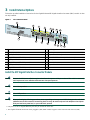
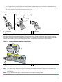
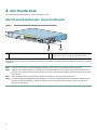
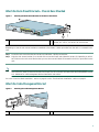
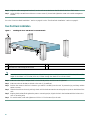
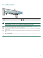
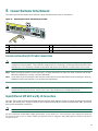
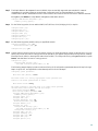
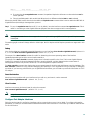
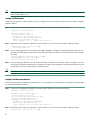
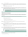
Quick Start Guide
Cisco 7301 Router
1
Documentation and Resources
2
Prepare for Installation
3
Install External Options
4
Rack-Mount the Router
5
Connect the Router to the Network
6
Start the System
7
Configure the Router
8
After Installation
9
Obtaining Technical Assistance
1 Documentation and Resources
Documentation for the Cisco 7301 router is online and orderable. For detailed hardware installation instructions, refer to the
online Cisco 7301 Installation and Configuration Guide. Refer to the following online documents for titles and links to related
documentation for installation and replacement of parts (including port adapters), regulatory compliance information, and
troubleshooting information and tools.
• All Cisco 7301 documentation—See the Cisco 7301 Internet Router Documentation Roadmap at
http://www.cisco.com/univercd/cc/td/doc/product/core/7301/4878.htm
• Port adapter documentation—See the Cisco 7301 Router Port Adapter Documentation Roadmap at
http://www.cisco.com/univercd/cc/td/doc/product/core/7301/4879.htm
• Troubleshooting documentation and tools—See the Cisco 7301 Internet Router Troubleshooting Documentation Roadmap
at http://www.cisco.com/univercd/cc/td/doc/product/core/7301/4951.htm
Documentation Survey
Is Cisco documentation helpful? Click here or go to http://www.cisco.com/warp/public/732/docsurvey/rtg/ to give us your
feedback.
Obtaining Documentation
Cisco provides several ways to obtain documentation, technical assistance, and other technical resources. These sections explain
how to obtain technical information from Cisco Systems.
Cisco.com
You can access the most current Cisco documentation on the World Wide Web at this URL:
http://www.cisco.com/univercd/home/home.htm
You can access the Cisco website at this URL:
http://www.cisco.com
International Cisco websites can be accessed from this URL:
http://www.cisco.com/public/countries_languages.shtml
Documentation CD-ROM
Cisco documentation and additional literature are available in a Cisco Documentation CD-ROM package, which may have
shipped with your product. The Documentation CD-ROM is updated regularly and may be more current than printed
documentation. The CD-ROM package is available as a single unit or through an annual or quarterly subscription.
Registered Cisco.com users can order a single Documentation CD-ROM (product number DOC-CONDOCCD=) through the
Cisco Ordering tool:
http://www.cisco.com/en/US/partner/ordering/ordering_place_order_ordering_tool_launch.html
All users can order annual or quarterly subscriptions through the online Subscription Store:
http://www.cisco.com/go/subscription
Click Subscriptions & Promotional Materials in the left navigation bar.
Ordering Documentation
You can find instructions for ordering documentation at this URL:
http://www.cisco.com/univercd/cc/td/doc/es_inpck/pdi.htm
You can order Cisco documentation in these ways:
• Registered Cisco.com users (Cisco direct customers) can order Cisco product documentation from the Networking Products
MarketPlace:
2
http://www.cisco.com/en/US/partner/ordering/index.shtml
• Nonregistered Cisco.com users can order documentation through a local account representative by calling Cisco Systems
Corporate Headquarters (California, USA) at 408 526-7208 or, elsewhere in North America, by calling 800 553-NETS
(6387).
Documentation Feedback
You can submit e-mail comments about technical documentation to [email protected].
You can submit comments by using the response card (if present) behind the front cover of your document or by writing to the
following address:
Cisco Systems
Attn: Customer Document Ordering
170 West Tasman Drive
San Jose, CA 95134-9883
We appreciate your comments.
3
2 Prepare for Installation
This section contains information about tools and parts, warnings, site preparation information, and information for
workbench or tabletop installation and rack-mount installation.
Warning
Only trained and qualified personnel should install, replace, or service this equipment.
Warning
Read the installation instructions before you connect the system to its power source.
Warning
This unit is intended for installation in restricted access areas. A restricted access area is where access can only
be gained by service personnel through the use of a special tool, lock and key, or other means of security, and is
controlled by the authority responsible for the location.
Warning
The Ethernet 10BASET, Token Ring, console, and auxiliary ports contain safety extra-low voltage (SELV) circuits.
The BRI and DSU/CSU circuits are treated like telephone-network voltage (TNV) circuits. Avoid connecting SELV
circuits to TNV circuits.
Before beginning this router installation, read the Cisco 7300 Series Internet Routers Regulatory Compliance and Safety
Information.
Site Preparation and Unpacking
• Lift the router safely out of the packing container.
• Ensure the power service at the site is suitable for the router you are installing.
• Check the packing slip to ensure that all the proper components are present.
• Locate and have accessible the Site Log for recording information about this installation.
Tools and Parts
Use the following list of tools and parts as a checklist for preparing for installing the Cisco 7301 router:
• ESD-preventative wrist strap
• Power cord and AC power cable-retention clip
• Appropriate cables to connect the router to the network and to the console terminal
• One serial port adapter cable for each serial port to connect the port with the remote device or network Ethernet transceiver
• Data service unit (DSU) to connect each serial port to an external network
• Tape measure and level
• Screwdrivers: Number 2 Phillips screwdriver and 3/16-inch flat-blade screwdriver
• Grounding lug and wires:
– A grounding lug with two number-10 screw holes with a 0.63-inch (16.002-mm) spacing between them
– A wire receptacle large enough to accept a 6-AWG multistrand, copper wire
– Two Phillips machine screws with locking washers—M5 (metric), 0.031-inch (.08-mm) pitch, 0.315-inch (8-mm) length
– A crimping tool to fit the grounding lug wire receptacle
– One grounding wire—6-AWG, 0.162-inch (4.115-mm) diameter, with approximately 0.108-inch (2.743-mm)
insulation, for a total wire diameter of approximately 0.27 inches (6.858 mm). The wire length depends on your router
location and site environment.
4
• The rack-mount and cable-management kit:
– Two rack-mount brackets and one cable-management bracket
– Screws: Four 12-24 x 0.5-inch screws, four 8-18 x .37-inch screws for use with a 19-inch rack, four 8 x .375-inch screws
for use in a 21–23-inch rack, and one M4 x 20-mm screw
• T1 channel service unit/data service unit (CSU/DSU) that converts the High-Level Data Link Control (HDLC) synchronous
serial data stream into a T1 data stream with the correct framing and ones density to connect a serial port to a T1 network.
(Some telephone systems require a minimum number of 1 bits per time unit in a data stream, called ones density.) Several
T1 CSU/DSU devices are available as additional equipment, and most provide a V.35, EIA/TIA-449, or EIA-530 electrical
interface.
Prepare for Workbench or Tabletop Installation
For a workbench or tabletop installation, verify the following before installing the router:
• The router is off the floor and has adequate ventilation.
• An adequate chassis ground (earth) connection exists for the router.
• The router has at last 3 inches (7.62 cm) of clearance at the inlet and exhaust vents (sides of router).
• The router has 19 inches (48.3 cm) clearance at the front and rear to allow for CompactFlash Disk, SFP Gigabit Interface
Converter (GBIC) module, and port adapter replacement or installation, or to access cables or equipment.
• The port adapter filler panel is installed if a port adapter is not installed. The slot must not be empty.
For cable-management bracket installation instructions, see page 9.
Prepare for Rack-Mount Installation
Before you begin the rack-mounting tasks, decide whether or not you want to front- or rear-mount the chassis, decide whether
or not you want to attach the cable-management bracket, and determine the type of rack—four-post or two-post—that you will
be using.
5
3 Install External Options
This section provides installation instructions for the Gigabit Ethernet SFP Gigabit Interface Converter (GBIC) module. It does
not ship installed.
Figure 1
Cisco 7301 Front Panel
1
3
S IER
LL R RM
CE CAR LA
RX RX RX A
5
7
9 10
ATM
SLOT 1
GIGABIT ETH
ERNET 0/0
RJ45 EN
LINK
TX GBIC
RX
GIGABIT ETH
ERNET 0/1
RJ45 EN
LINK
TX GBIC
RX
GIGABIT ETH
ERNET 0/2
RJ45 EN
LINK
TX GBIC
AUX
RX
12
14
CONSOLE
CISCO 73
100 -24 0V,
2A, 50/ 60
Hz
24V =9 A,
48 - 60V =5
A
ALARM
01
COMPACT
FLASH
STATUS
4
A
B
2
6
8
11 13
15
80265
D
LE
AB
EN
16
1
Port adapter
9
2
Port adapter latch
10 Console port
3
RJ-45 port GE 0/0
11 CompactFlash Disk ejector button
4
Gigabit Ethernet SFP GBIC port 0/0
12 Ground for ESD wrist strap with banana jack
5
RJ-45 port GE 0/1
13 Alarm port
6
Gigabit Ethernet SFP GBIC port 0/1
14 Power switch
7
RJ-45 port GE 0/2
15 CompactFlash Disk slot
8
Gigabit Ethernet SFP GBIC port 0/2
16 Power connector
Auxiliary port
Install the SFP Gigabit Interface Converter Module
Warning
Because invisible laser radiation may be emitted from the aperture of the port when no fiber cable is connected,
avoid exposure to laser radiation and do not stare into open apertures.
Warning
Class 1 laser product.
Warning
Class 1 LED product.
Warning
When performing the following procedures, wear a grounding wrist strap to avoid ESD damage to the card. Some
platforms have an ESD connector for attaching the wrist strap. Do not directly touch the midplane or backplane
with your hand or any metal tool, or you could shock yourself.
• Only three of the six Gigabit Ethernet ports may be used at the same time.
• The Gigabit Ethernet small form-factor pluggable (SFP) GBIC module supports online insertion and removal (OIR).
6
• The native fiber optical Gigabit Ethernet ports and the RJ-45 Gigabit Ethernet ports are reported as GigabitEthernet 0/0,
GigabitEthernet 0/1, and GigabitEthernet 0/2 in software. You must use the media-type command to select which media type
you want to use before you configure these ports. See page 24.
Figure 2
Identifying SFP GBIC Module Latches
2
3
80755
1
1
Sliding latch
3
2
Hinged and sliding latch
Hinged latch
Different manufacturers have different types of latching mechanisms for Gigabit Ethernet SFP GBIC modules. There is no
correlation of the type of latch to the model (such as SX or LH) or technology type (such as Gigabit Ethernet) of SFP GBIC
modules. See the label for the SFP technology type and model. The SFP GBIC modules use LC-type connectors.
Figure 3
Inserting a SFP GBIC Module into a SFP GBIC Port
TX GBIC
RX
1
ETHERNET
0/0
LINK
TX GBIC
RX
GIGABIT ET
HERNET 0/1
RJ45 EN
LINK
TX GBIC
RX
GIGABIT ET
HERNET 0/2
RJ45 EN
LINK
TX GBIC
RX
AUX
CONSOLE
T
X
X
R
2
1
COMPAC
FLASH
80269
SERIES
SFP GBIC port
2
Latch beneath plug
Step 1
Turn the SFP GBIC module so the latch is on the bottom. The SFP GBIC module is keyed to be inserted correctly.
Step 2
Insert the SFP GBIC module into SFP port 0/0, 0/1, or 0/2. Repeat Step 2 if you are inserting a second or third SFP
GBIC module.
Step 3
Do not remove the SFP GBIC module plugs until you are ready to install the cables.
7
4 Rack-Mount the Router
This section provides information for rack-mounting the router.
Attach the Rack-Mount Brackets—Chassis Front-Mounted
Figure 4
Attaching the Rack-Mount Brackets to the Front of the Chassis
D
LE
AB
EN
S IER
LL R RM
CE CAR LA
RX RX RX A
ATM
GIGABIT ETHER
NET
RJ45 EN
GIGABIT ETHER
NET
RX
RJ45 EN
0/1
LINK
TX GBIC
GIGABIT ETHER
NET
RX
RJ45 EN
0/2
LINK
TX GBIC
AUX
RX
CONSOLE
ALARM
COMPACT
FLASH
100-24 0V,
2A, 50/60
Hz
24V=9 A,
48 - 60V=5
A
STATUS
A
B
CISCO 7301
0/0
LINK
TX GBIC
80906
SLOT 1
1
1
Rack-mount bracket
2
2
4 screws, 8-18 x .37 in., for use with a 19-inch rack
4 screws, 8 x .375 in., for use in a 21–23-inch rack
Depending on how the rack-mount brackets are attached to the chassis, the chassis either protrudes from the rack or is recessed
in the rack.
Step 1
Locate the rack-mount and cable-management brackets and screws and a Number 2 Phillips screwdriver.
Step 2
Align the rack-mount bracket (1) to the side of the router. Depending on which set of rack-mount bracket holes you
choose to use to attach the rack-mount bracket to the router, the chassis will either be recessed in the rack or protrude
from the rack.
Step 3
Insert and tighten the two screws (2). Repeat Step 1 and Step 2 on the other side of the router.
Step 4
To install the cable-management bracket, see page 9. If you are not installing the cable-management bracket, skip to
the “Four-Post Rack Installation” section on page 10 or the “Two-Post Rack Installation” section on page 11 for
rack-mount instructions.
8
Attach the Rack-Mount Brackets—Chassis Rear-Mounted
Figure 5
EN
AB
LE
Attaching the Rack-Mount Brackets to the Rear of the Chassis
2
D
S IER
LL R RM
CE CAR LA
RX RX RX A
ATM
SLOT 1
GIGABIT ETHER
NET
RJ45 EN
0/0
LINK
TX GBIC
GIGABIT ETHER
NET
RX
RJ45 EN
0/1
LINK
TX GBIC
GIGABIT ETHER
NET
RX
RJ45 EN
0/2
LINK
TX GBIC
AUX
CONSOLE
RX
CISCO 7301
ALARM
100-24 0V,
2A, 50/60
Hz
24V=9 A,
48 - 60V=5
A
STATUS
1
1
2
Rack-mount bracket
80907
A
B
COMPACT
FLASH
4 screws, 8-18 x .37 in., for use with a 19-inch rack
4 screws, 8 x .375 in., for use in a 21–23-inch rack
Depending on how the rack-mount brackets are attached to the chassis, it either protrudes from the rack or is recessed in the
rack.
Step 1
Locate the rack-mount brackets and screws and a Number 2 Phillips screwdriver.
Step 2
Align the rack-mount bracket (1) to the side of the router and insert and tighten the screws (2). Depending on which
set of holes on the rack-mount bracket that you use, the router will either be recessed in the rack or protrude from the
rack.
Note
To use the cable-management bracket with the Cisco 7301 router rear-mounted, you must purchase a second
rack-mount kit, attach a rack-mount bracket to the left front of the chassis, and attach the cable-management bracket
to it. See below for cable-management bracket installation instructions.
Go to the “Four-Post Rack Installation” section on page 10 or the “Two-Post Rack Installation” section on page 11.
Attach the Cable-Management Bracket
Figure 6
Attaching the Cable-Management Bracket
1
D
LE
AB
S IER
LL R RM
CE CAR LA
RX RX RX A
80278
EN
2
1
Cable-management bracket
2
M4 x 20-mm screw
9
Step 1
Align the cable-management bracket (1) to the rack-mount bracket on the left side of the Cisco 7301 router.
Step 2
Using a Phillips screwdriver and the M4 x 20-mm screw (2), thread and tighten the screw to the cable-management
bracket.
Go to the “Four-Post Rack Installation” section on page 10 or the “Two-Post Rack Installation” section on page 11.
Four-Post Rack Installation
Figure 7
Installing the Cisco 7301 Router in a Four-Post Rack
1
D
LE
AB
EN
S IER
LL R RM
CE CAR LA
RX RX RX A
ATM
GIGABIT ETHER
NET
RJ45 EN
GIGABIT ETHER
NET
RX
RJ45 EN
0/1
LINK
TX GBIC
GIGABIT ETHER
NET
RX
RJ45 EN
0/2
LINK
TX GBIC
AUX
RX
CONSOLE
100-24 0V,
2A, 50/60
Hz
24V=9 A,
48 - 60V=5
A
ALARM
COMPACT
FLASH
STATUS
A
2
CISCO 7301
0/0
LINK
TX GBIC
B
SLOT 1
80908
3
1
Four-post rack
2
Screw hole for cable-management bracket
3
Four 12-24 x 0.5-inch screws
Note
Inner clearance (the width between the inner sides of the two posts or rails) must be at least 17.3 inches (43.9 cm) The
height of the chassis is 1.73 inches (4.39 cm). Airflow through the chassis is from front to back.
Step 1
Make sure that the port adapter latch is in the locked position and the screw is tightened.
Step 2
Make sure the rack brakes are locked or the rack (1) is stabilized.
Step 3
Position the router so the front is closest to you and lift it carefully into the rack. To prevent injury, avoid any sudden
twists or moves.
Step 4
Slide the chassis into the rack, pushing it back until the brackets meet the mounting strips or posts on both sides of the
rack.
Step 5
Keeping the brackets flush against the posts or mounting strips, align the holes in the brackets with the holes on the
rack or mounting strip.
Step 6
For each bracket, insert and tighten two 12-24 x 0.5-inch screws (3) to the rack.
10
Two-Post Rack Installation
Figure 8
Installing the Cisco 7301 Router in a Two-Post Rack
1
D
LE
AB
EN
R
LS RIE M
CEL CAR AR
RX RX RX AL
ATM
GIGABIT ETHERNE
T 0/0
2
LINK
TX GBIC
GIGABIT ETHERNE
T 0/1
RX
RJ45 EN
LINK
TX GBIC
GIGABIT ETHERNE
T 0/2
RX
RJ45 EN
LINK
TX GBIC
AUX
CONSOLE
RX
ALARM
COMPACT
FLASH
100-240V
, 2A, 50/60
Hz
24V=9A,
48 - 60V=5A
80909
CISCO 7301
STATUS
B
RJ45 EN
A
SLOT 1
1
Two-post rack
2
Screw hole for cable-management bracket
3
3
Four 12-24 x 0.5-inch screws
Note
Inner clearance (the width between the inner sides of the two posts or rails), must be at least 17.3 inches (43.9 cm) The
height of the chassis is 1.73 inches (4.39 cm). Airflow through the chassis is from front to back.
Step 1
Make sure that the port adapter latch is in the locked position and the screw is tightened.
Step 2
Make sure the rack brakes are locked or the rack (1) is stabilized.
Step 3
Position the router so the front is closest to you and lift it carefully into the rack. To prevent injury, avoid any sudden
twists or moves.
Step 4
Slide the chassis into the rack, pushing it back until the brackets meet the mounting strips or posts on both sides of the
rack.
Step 5
Keeping the brackets flush against the posts or mounting strips, align the holes in the brackets with the holes on the
rack or mounting strip.
Step 6
For each bracket, insert and tighten two 12-24 x 0.5-inch screws (3) to the rack.
11
Chassis Ground Connection Installation
Warning
This equipment is intended to be grounded. Ensure that the host is connected to earth ground during normal use.
Figure 9
Attaching the Grounding Lug and Wire to the Chassis
3
2
50536
4
1
1
Chassis ground connector
3
Screws
2
Grounding lug
4
Wire
Note
The grounding lug and Phillips screws are not available from Cisco Systems. Get the grounding lug from an
electrical-connector vendor and the screws from a hardware vendor. See Page 4 for the parts needed.
Step 1
Use the wire stripper to strip one end of the 6-AWG wire approximately 0.75 inches (19.05 mm).
Step 2
Insert the 6-AWG wire (4) into the wire receptacle on the grounding lug.
Step 3
Use the crimping tool to carefully crimp the wire receptacle around the wire; this step is required to ensure a proper
mechanical connection.
Step 4
Locate the chassis ground connector (1) on the rear of your router chassis.
Step 5
Insert the two screws (3) through the holes in the grounding lug (2).
Step 6
Use the Number 2 Phillips screwdriver to carefully tighten the screws until the grounding lug is held firmly to the
chassis. Do not overtighten the screws.
Step 7
Connect the opposite end of the grounding wire to the appropriate grounding point at your site to ensure an adequate
chassis ground.
12
5 Connect the Router to the Network
This section provides information about cables and ports and attaching the router to the network.
Figure 10
Attaching the Console and Auxiliary Port Cables
1
GIGABIT ETH
ERNET 0/0
RJ45 EN
LINK
TX GBIC
RX
GIGABIT ETH
ERNET 0/1
RJ45 EN
LINK
TX GBIC
RX
GIGABIT ETH
ERNET 0/2
RJ45 EN
LINK
TX GBIC
CISCO 73
AUX
RX
2
CONSOLE
ALARM
01
100 -24 0V,
2A, 50/ 60
Hz
24V =9 A,
48 - 60V =5
A
STATUS
A
3
4
80273
B
COMPACT
FLASH
5
1
Auxiliary port
4
Cable to modem or DCE
2
Console port
5
Cable to console terminal or DTE
3
RJ-45 connector
Console and Auxiliary Port Cable Connections
Note
Both the console and auxiliary ports are asynchronous serial ports; any devices connected to these ports must be capable
of asynchronous transmission. The DCE-mode console port is for connecting a console terminal and the DTE-mode
auxiliary port is for connecting a modem or other DCE device (such as a CSU/DSU or other router) to your router.
Step 1
Before connecting a terminal to the console port, configure the terminal to match the router console port as follows:
9600 baud, 8 data bits, no parity, 1 stop bit (9600 8N1).
Step 2
Use an auxiliary and console port cable. Use the console cable to connect the terminal to the console port. After you
establish normal router operation, you can disconnect the terminal.
Note
You must supply your own interface cable between the auxiliary port and the equipment you are connecting. For
console and auxiliary port pinouts, see the online Cisco 7301 Installation and Configuration Guide.
Gigabit Ethernet SFP GBIC and RJ-45 Connections
The Cisco 7301 router has three native Gigabit Ethernet interfaces. Each interface consists of three RJ-45 media ports and three
SFP GBIC optical fiber ports. The RJ-45 media ports provide 10/100/1000-Mbps connectivity while the SFP GBIC optical fiber
ports provide 1000-Mbps connectivity.
Note
Any three of the six Gigabit Ethernet ports may be used at the same time.
For more information on SFP GBIC cabling specifications, see the online Cisco 7301 Installation and Configuration Guide and
the Gigabit Interface Converter (GBIC) Module and Small Form-Factor Pluggable (SFP) GBIC Module Installation Information
and Specifications.
13
Figure 11
1
Gigabit Ethernet SFP GBIC and RJ-45 Port Identification
2
GIGABIT ETH
ERNET 0/0
RJ45 EN
LINK
TX GBIC
3
RX
4
GIGABIT ETH
ERNET 0/1
RJ45 EN
LINK
TX GBIC
5
6
GIGABIT ETH
ERNET 0/2
RX
RJ45 EN
LINK
TX GBIC
RX
AUX
CONSOLE
CISCO 73
01
80274
CO
FL
1
Gigabit Ethernet RJ-45 port 0/0
4
Gigabit Ethernet SFP GBIC port 0/1
2
Gigabit Ethernet SFP GBIC port 0/0
5
Gigabit Ethernet RJ-45 port 0/2
3
Gigabit Ethernet RJ-45 port 0/1
6
Gigabit Ethernet SFP GBIC port 0/2
Intra-Building Lightning Protection
Shielded cables which are grounded at both ends are required to be used on the 10/100/1000 Ethernet port in order to be in
compliance with requirement R4-11 in GR-1089-Core for a Central Office environment. This is not a requirement for customer
premise installations.
Warning
To avoid electric shock, do not connect safety extra-low voltage (SELV) circuits to telephone-network voltage
(TNV) circuits. LAN ports contain SELV circuits, and WAN ports contain TNV circuits. Some LAN and WAN ports
both use RJ-45 connectors. Use caution when connecting cables.
To identify the RJ-45 cable type, hold the two ends of the cable next to each other so you can see the colored wires inside the ends.
The straight-through wire type has colored wires in the same sequence at both ends. In the crossover wire type, the first colored
wire at the far left is the third colored wire at the other end. The second colored wire at the far left is the sixth colored wire at the
other end.
Attach RJ-45 Ethernet cables to the appropriate connector.
Note
Both native Gigabit Ethernet ports, SFP GBIC and RJ-45, are reported as Gigabit Ethernet 0/0, Gigabit Ethernet 0/1,
and Gigabit Ethernet 0/2 in software. You must use the media-type command to select which media type you want to
use before you configure these ports. See the “Configure the Native Gigabit Ethernet Interfaces” section on page 24.
SFP GBIC Cabling and Connection Equipment
The Gigabit Ethernet small form-factor pluggable (SFP) GBIC module port is a 1000-Mbps optical interface in the form of an
LC-type duplex port that supports IEEE 802.3z interfaces compliant with the 1000BASEX standard. Gigabit Ethernet SFP GBIC
models GLC-SX-MM, GLC-LH-SM, and GLC-ZX-SM are supported in the Cisco 7301 router, as are a variety of Coarse
Wavelength-Division Multiplexing (CWDM) SFPs, and the Cisco 1000BASE-T (copper) SFP with an RJ-45 port. For cabling
distances, specifications, and other information, see the online Gigabit Interface Converter (GBIC) Module and Small
Form-Factor (SFP) GBIC Module Installation Information and Specifications. Also see the Coarse Wavelength- Division
Multiplexing SFP Compatability Matrix at http://www.cisco.com/en/US/products/hw/modules/ps4999/
products_quick_reference_guide09186a008019f055.html, the Cisco Small Form-Factor Pluggable Gigabit Interface Converter
Data Sheet, and the Cisco 1000BASE-T SFP Data Sheet.
Note
14
All SFP GBIC ports have LC-type connectors.
B ecause invisible laser radiation may be emitted from the aperture of the port when no fiber cable is connected,
Warning
avoid exposure to laser radiation and do not stare into open apertures.
Warning
Class 1 laser product.
Warning
Class 1 LED product.
Figure 12
Inserting the Gigabit Ethernet SFP GBIC Cables
4
6
5
ABIT ETHE
RNET 0/0
LINK
TX GBIC
RX
GIGABIT ET
HERNET 0/1
RJ45 EN
LINK
TX GBIC
GIGABIT ET
HERNET 0/2
RX
RJ45 EN
CISCO 74
CISCO 7400SERIES
11
AUX
CONSOLE
CO
FL
2
3
80749
1
LINK
TX GBIC
RX
1
To external 1000BASEX network
4
Gigabit Ethernet SFP GBIC port 0/1
2
1 duplex connector (TX and RX)
5
RX
3
SFP GBIC module
6
TX
Note
There is no support for copper-based SFP GBICs (1000BASET) as these do not conform to the SFP GBIC standard and
have not been validated by Cisco.
Step 1
Remove the SFP GBIC plug.
Step 2
Attach the appropriate optical fiber cable directly to SFP GBIC module. You can use either simplex or duplex
connectors for most devices.
• Two cables are required for simplex connectors, one cable for transmit (TX) and one for receive (RX).
• One cable that has both TX and RX connectors is required for duplex connectors.
Use a Category 5 unshielded twisted pair cable with RJ-45 connector, if you are using a Cisco 1000BASE-T SFP.
Caution
If you plan to use a GLC-LH-SM at distances greater than 984.25 feet (300 meters) over 50/125-micron or
62.5/125-micron multimode fiber, to prevent data transmission problems you must use the mode-conditioning
patch cord.
15
Attach the Mode-Conditioning Patch Cord
Figure 13
Attaching the Mode-Conditioning Patch Cord
4
1
//
2
//
Offset
7
//
TX
RX
3
5
6
7
4
84159
8
1
Gray color identifier
5
Single-mode bar
2
To GE interface
6
Offset
3
Blue color identifier
7
Beige color identifier
4
Multimode bar
8
To cable plant
Step 1
Attach the patch cord to the LC-type connector on the SFP GBIC modules (2).
Step 2
Attach the network ends of your patch cord to the appropriate 1000BASEX equipment in your building cable plant (9).
Note
Ensure that you connect the TX and RX ports on one end of the patch cord to the RX and TX ports (respectively) on
the other end. Connect TX to RX and RX to TX.
A mode-conditioning patch cord can be used with the GLC-SX-MM or GLC-LH-SM to allow reliable laser transmission
between the single-mode laser source on the SFP GBIC module and a multimode optical fiber cable.
Port Adapter Cable Connections
The instructions for connecting the cables for each port adapter installed in the Cisco 7301 router are in the respective online
notes for each port adapter. The documents are available on the Documentation CD-ROM and on Cisco.com at
http://www.cisco.com/univercd/cc/td/doc/product/core/cis7300/ol3531.htm. Also see the release notes for information about a
specific port adapter. Release notes are found at http://www.cisco.com/univercd/cc/td/doc/product/software/index.htm.
16
Alarm Port Connection
Figure 14
Connecting the Alarm Port Cable
1
CONSOLE
ALARM
80279
COMPACT
FLASH
STATUS
1
Alarm port
Connect the dry relay alarm port cable connector to the alarm port. It cannot be inserted incorrectly.
The dry relay alarm port operates up to 50V AC/DC maximum and up to 80 mA maximum. Total power dissipation should not
exceed 300 milliwatts. The normally closed position will have from 15 to 30 ohms resistance. The open position will be greater
than 1 megohm. The alarm condition is the closed position. This port is a switch so that the cable connector can be inserted in
either orientation.
Cable Management
Figure 15
Inserting the Cables Through the Cable-Management Bracket
2
D
LE
AB
EN
S IER
LL R RM
CE CAR LA
RX RX RX A
ATM
GIGABIT ETHER
NET
RJ45 EN
CISCO 7400
GIGABIT ETHER
NET
RX
RJ45 EN
0/1
LINK
TX GBIC
GIGABIT ETHER
NET
RX
RJ45 EN
0/2
LINK
TX GBIC
AUX
RX
CONSOLE
ALARM
COMPACT
FLASH
100-24 0V,
2A, 50/60
Hz
24V= 9A,
48 - 60V=5
A
STATUS
A
B
CISCO 7301SERIES
0/0
LINK
TX GBIC
80280
SLOT 1
1
1
Input/output cables
2
Cable-management bracket
If you have not already done so, run the port adapter and input/output cables through the cable-management bracket.
17
6 Start the System
Connect Power to the Router
This section provides instructions for attaching the power cables to the router and powering on the router.
Warning
This unit might have more than one power cord. To reduce the risk of electric shock, disconnect the two power
supply cords before servicing the unit.
Warning
This product relies on the building’s installation for short-circuit (overcurrent) protection. Ensure that a fuse or
circuit breaker no larger than 120 VAC, 15A U.S. (240 VAC, 10A international) is used on the phase conductors (all
current-carrying conductors.)
The Cisco 7301 router comes with either an AC or DC power supply. Dual AC and dual DC power supply options are available.
Connect AC-Input Power
Step 1
Check that the power switch is in the OFF (O) position.
Step 2
Plug the single power cable into the AC connector on the router. The cable is keyed so that it cannot be inserted
incorrectly.
Figure 16
Attaching the AC Power Cable
2
LE
ALARM
100 -24 0V,
2A, 50/6 0
Hz
24V =9 A,
48 - 60V =5
A
80281
COMPACT
FLASH
STATUS
1
1
AC power receptacle
2
Adjustable AC cable-retention clip
Step 3
If you are using the single AC power cable, insert the cable-retention clip wire into the retention-clip holes. See Figure 16.
Step 4
Slide the plastic part of the cable-retention clip into the wire holder.
Step 5
Place the AC power cable into the adjustable cable-retention clip.
Step 6
Plug a power cable into each end of the dual AC power cord that is attached to the router.
Step 7
Plug the single AC power supply cable into a single AC power source.
Step 8
Plug the dual AC power supply cables into two AC power sources.
Note
After powering off the router, wait a minimum of 30 seconds before powering it on again.
Note
If required, use Sinewave Output UPS (uninterruptable power supply), not Ferro-resonant type UPS.
18
Connect DC-Input Power
The color coding of the DC-input power supply leads depends on the color coding of the DC power source at your site. Match
the lead color coding for the DC-input power supply to the lead color coding used at the DC power source.
Warning
This product relies on the building’s installation for short-circuit (overcurrent) protection. Ensure that a Listed and
Certified fuse or circuit breaker no larger than 60 VDC, 15 A is used on all currently-carrying conductors.
Warning
Before completing any of the following steps, and to prevent short-circuit or shock hazards, ensure that power is
removed from the DC circuit. To ensure that all power is OFF, locate the circuit breaker on the panel board that
services the DC circuit, switch the circuit breaker to the OFF position, and tape the switch handle of the circuit
breaker in the OFF position.
Step 1
Be sure the power switch is in the OFF (O) position.
Step 2
Ensure that no current is flowing through the DC power supply leads. To ensure that all power is OFF, locate the circuit
breaker on the panel board that services the DC circuit, switch the circuit breaker to the OFF position, and tape the
switch handle of the circuit breaker in the OFF position.
Step 3
Using a wire stripper, strip approximately 0.55 inch (14 mm) from the –V and +V leads.
Figure 17
Attaching the Wires to the DC Plug and the DC Plug to the DC Connector
LE
LE
ALARM
4
A
A
B
STATUS
B
COMPACT
FLASH
STATUS
3
1
80283
ALARM
COMPACT
FLASH
5
2
1
DC plug
4
Single DC power supply connector
2
Lead
5
Dual DC power supply connectors
3
+ and – embossed on connector
Step 4
To determine which lead to connect to which screw in the DC plug, align the DC plug (1) with the DC connector (4,
5) in the chassis as shown in the illustration above. Do not insert the plug in the connector. Notice the symbols, + A –,
embossed on the connector (3). Use the symbols and the orientation of the plug to guide you when inserting the leads
into the plug.
Step 5
Loosen the screws in the DC plug (1), insert the +V and –V leads, and tighten the screws.
Step 6
Insert the DC plug (1) into the DC connector (4) in the chassis. Repeat Step 5 and Step 6 if you have a dual DC power
supply (5).
Step 7
Switch the circuit breaker to the ON position.
Step 8
Press the power switch to turnon the router.
Note
After powering off the router, wait a minimum of 30 seconds before powering it on again.
19
Observe the System Startup and Perform a Basic Configuration
Check conditions prior to system startup:
Step 1
Check that all hardware parts and cables are securely attached to the chassis.
Step 2
Check that port adapter configuration information is available, if needed.
Step 3
Check that a CompactFlash Disk is installed.
Step 4
Check that the console terminal is turned on.
Start the Router
Step 1
Place the power switch in the ON (|) position.
Step 2
Listen for the fans; they should be operating as soon as power is turned on. The following table provides information
about the LEDs as the system starts.
Figure 18
Identifying LEDs and LED Status
GIGABIT ETH
ERNET 0/0
RJ45 EN
LINK
TX GBIC
RX
GIGABIT ETH
ERNET 0/1
RJ45 EN
LINK
TX GBIC
RX
GIGABIT ETH
ERNET 0/2
RJ45 EN
LINK
TX GBIC
RX
AUX
CONSOLE
CISCO 73
ALARM
01
B
3
4
5
6
80266
2
A
1
100 -24 0V,
2A, 50/ 60
Hz
24V =9 A,
48 - 60V =5
A
COMPACT
FLASH
STATUS
7
No.
LED Label
LED
Color
Status
LED flashes when
there is traffic
1
LINK (0/0)
LINK (0/0)
Green
—
Yes
2
RJ-45 EN (0/0) RJ-45 enable (0/0) Green
In the Power Up state, No, remains
the LED is On
constantly on
3
LINK (0/1)
—
4
RJ-45 EN (0/1) RJ-45 enable (0/1) Green
In the Power Up state, No, remains
the LED is On
constantly on
5
LINK (0/2)
—
6
RJ-45 EN (0/2) RJ-45 enable (0/2) Green
In the Power Up state, No, remains
the LED is On
constantly on
7
STATUS
—
LINK (0/1)
LINK(0/2)
System status
Green
Green
Amber while the system boots
Green when the system is
operational
Yes
Yes
No, remains
In the Power Up state, constantly on
the LED is On
Step 3
During the boot process, observe the system LEDs. The STATUS LED comes on immediately as amber, then turns to
green when the Cisco IOS is booted. Port adapter LEDs go on and off irregularly.
Step 4
Observe the initialization process. The port adapter ENABLED LEDs go on when initialization is completed and the
console screen displays a script and system banner.
20
7 Configure the Router
Before configuring the router, determine whether or not you want to use a management tool such as Cisco Security Device
Manager.
Cisco Security Device Manager (SDM), version 1.1, is an optional Java-based device-management tool that allows you to
configure LAN interfaces, routing, Network Address Translation (NAT), firewalls, Virtual Private Networks (VPNs), and other
features without knowledge of the Cisco command-line interface (CLI). You can configure features such as Access Control Lists
(ACLs), routing protocols, and other options using SDMs advanced mode.
Note
You will need to use CLI commands to configure several features that SDM does not support. SDM does not support
the following features: WAN configuration, Gigabit Ethernet (GE) interfaces, AA client, EZ VPN server, QoS,SSHv2,
DHCP server configuration options, and usability enhancements.
SDM is preinstalled on your routers Flash Disk or CompactFlash Disk when it is ordered as part of a VPN bundle or as part of
a 7xxx VPN bundle. If your router did not ship with SDM preinstalled, you can download a free copy from the Software Center
at Cisco.com at http://ww.cisco.com/kobayashi/sw-center/index.shtm. Because SDM uses a GUI, it requires that you access it
from a PC using a supported web browser. Go to the Security Device Manager (SDM), Version 1.1 User Note for the 7xxx
Routers for more information.
Performing a Basic Configuration Using the Setup Facility
If you do not plan to use AutoInstall, do not connect the router’s serial (WAN) cable to the channel service unit/data service
unit (CSU/DSU). If the WAN cable is not connected, the router boots from Flash memory and goes automatically into the setup
facility.
You can run the setup facility any time you are at the enable prompt (#) by entering the setup command.
If the serial (WAN) cable is connected to the CSU/DSU and the router does not have a configuration stored in NVRAM, the
router attempts to run AutoInstall at startup. The router may take several minutes to determine that AutoInstall is not set up
to a remote TCP/IP host. Once the router determines that AutoInstall is not configured, it defaults to the setup facility.
Configure Global Parameters
When you first start the setup program, you must configure the global parameters. These parameters are used for controlling
system-wide settings. Complete the following steps to enter the global parameters:
Step 1
Connect a console terminal to the console port, and then boot the router.
The system boots from Flash memory. The following information appears after about 30 seconds. When you see this
information, you have successfully booted your router:
Restricted Rights Legend
Use, duplication, or disclosure by the Government is
subject to restrictions as set forth in subparagraph
(c) of the Commercial Computer Software - Restricted
Rights clause at FAR sec. 52.227-19 and subparagraph
(c) (1) (ii) of the Rights in Technical Data and Computer
Software clause at DFARS sec. 252.227-7013.
cisco Systems, Inc.
170 West Tasman Drive
San Jose, California 95134-1706
Cisco Internetwork Operating System Software
IOS (tm) 7301 Software (C7301-JS-M), Experimental Version 12.2(20030103:230909) [biff 100]
Copyright (c) 1986-2003 by cisco Systems, Inc.
Compiled Fri 03-Jan-03 16:03 by biff
Image text-base:0x600088F4, data-base:0x617F6000
21
cisco 7301 (NPE-G1) processor (revision A) with 245760K/16384K bytes of memory.
Processor board ID 0
SB-1 CPU at 650Mhz, Implementation 1, Rev 0.2, 512KB L2 Cache
1 slot midplane, Version 2.0
Last reset from power-on
Bridging software.
X.25 software, Version 3.0.0.
SuperLAT software (copyright 1990 by Meridian Technology Corp).
TN3270 Emulation software.
3 Gigabit Ethernet/IEEE 802.3 interface(s)
509K bytes of non-volatile configuration memory.
125440K bytes of ATA PCMCIA card at slot 2 (Sector size 512 bytes).
32768K bytes of Flash internal SIMM (Sector size 256K).
Press RETURN to get started!
The first two sections of the configuration script (the banner and the installed hardware) appear only at initial system
startup. On subsequent uses of the setup facility, the script begins with a System Configuration Dialog as shown in the
following example.
--- System Configuration Dialog --At any point you may enter a question mark '?' for help.
Use ctrl-c to abort configuration dialog at any prompt.
Default settings are in square brackets '[]'.
Step 2
When asked if you want to enter the initial configuration dialog and see the current interface summary, enter yes or
press Return:
Would you like to enter the initial configuration dialog? [yes]:
First, would you like to see the current interface summary? [yes]:
In the following example, the summary shows a Cisco 7301 router at first-time startup; that is, nothing is configured.
Any interface listed with OK? value "NO" does not have a valid configuration
Interface
ATM1/0
FastEthernet1/0
Step 3
IP-Address
unassigned
unassigned
OK?
NO
NO
Method
unset
unset
Status
down
down
Choose which protocols to support on your interfaces. For Internet Protocol (IP)-only installations, you can accept the
default values for most of the questions. A typical configuration using IP, IPX, and AppleTalk follows and continues
through Step 8:
Configuring global parameters:
Enter host name [Router]:
Step 4
Enter enable secret, enable, and virtual terminal passwords:
The enable secret password is a one-way cryptographic secret
password used instead of the enable password when it exists.
Enter enable secret: barney
The enable password is used when there is no enable secret
password and when using older software and some boot images.
Enter enable password: betty
Enter virtual terminal password: fred
22
Protocol
down
down
Step 5
The Simple Network Management Protocol (SNMP) is the most widely supported open standard for network
management. It provides a means to access and set configuration and run-time parameters of routers and
communication servers. SNMP defines a set of functions that can be used to monitor and control network elements.
Enter yes or press Return to accept SNMP management; enter no to refuse it:
Configure SNMP Network Management? [yes]:
Community string [public]:
Step 6
For the following queries, do not enable VINES, LAT, DECnet, CLNS, bridging, XNS, or Apollo:
Configure
Configure
Configure
Configure
Configure
Configure
Configure
Step 7
Vines? [no]:
LAT? [no]:
DECnet? [no]:
CLNS? [no]:
bridging? [no]:
XNS? [no]:
Apollo? [no]:
For the following queries, enable routing on AppleTalk and IPX:
Configure AppleTalk? [no]: yes
Multizone networks? [no]: yes
Configure IPX? [no]: yes
Step 8
In most cases you use IP routing. If you are using IP routing, you must also select an interior routing protocol. You can
specify only one of two interior routing protocols to operate on your system using the setup facility: Interior Gateway
Routing Protocol (IGRP) or Routing Information Protocol (RIP). To configure IP routing, enter yes (the default) or press
Return, and then select an interior routing protocol:
Configure IP? [yes]:
Configure IGRP routing? [yes]:
Your IGRP autonomous system number [1]: 15
The following sample display includes a continuous listing of all configuration parameters selected in Step 3 through
Step 8. Only IP, IPX, and AppleTalk are the selected protocols for this example.
Configuring global parameters:
Enter host name [Router]: router
The enable secret is a one-way cryptographic secret password used
instead of the enable password when it exists.
Enter enable secret: barney
The enable password is used when there is no enable secret password
and when using older software and some boot images.
Enter enable password: betty
Enter virtual terminal password: fred
Configure SNMP Network Management? [yes]:
Community string [public]:
Configure Vines? [no]:
Configure LAT? [no]:
Configure AppleTalk? [no]: yes
Multizone networks? [no]: yes
Configure DECnet? [no]:
Configure IP? [yes]:
Configure IGRP routing? [yes]:
Your IGRP autonomous system number [1]: 15
Configure RIP routing? [no]:
Configure CLNS? [no]: n
Configure bridging? [no]:
Configure IPX? [no]: yes
Configure XNS? [no]:
Configure Apollo? [no]:
23
Step 9
Save your settings to NVRAM. See the “Save the Running Configuration to NVRAM” section on page 28. If you do
not save the configuration settings that you created in the router using configuration mode and the setup facility, your
configuration will be lost the next time you reload the router.
Configure an Auxiliary Port to Receive Console Port Messages
If you choose to have console port messages routed to the auxiliary port, use the IOS command terminal monitor on the
auxiliary port on which you desire to receive console messages.
Router# terminal monitor
Configure the Native Gigabit Ethernet Interfaces
The Cisco 7301 reports both the RJ-45 and Gigabit Ethernet SFP GBIC interface ports as Gigabit Ethernet 0/0, Gigabit Ethernet
0/1, and Gigabit Ethernet 0/2. Before configuring any of the three interfaces, you must first use the media-type interface
command to select the media type, either the SFP GBIC (gbic) or RJ-45 (rj45) port.
Note
The Gigabit Ethernet interfaces on the Cisco 7301 do not support the Inter-Switch Link (ISL) VLAN encapsulation
protocol. We recommend that customers use the IEEE 802.1Q VLAN encapsulation protocol as an alternative. Where
an application requires the use of ISL, this can be provided by the Fast Ethernet or Gigabit Ethernet port adapters.
Note
The RJ-45 port is the default media.
Change the Media Type of the Native Gigabit Ethernet SFP GBIC or RJ-45 Ports
To be able to use a particular media port, use Cisco IOS to select the media type. This is done by using the media-type interface
command:
media-type { gbic | rj45 }
Example:
interface GigabitEthernet 0/1
media-type rj45
end
Configure the Interface Transmission and Speed Modes
Step 1
After changing the media type, configure the speed and transmission modes to appropriately match the new interface
characteristics. Changing the speed and duplex of a Cisco 7301 router Gigabit Ethernet interface is done using the speed
and duplex interface commands.
Note
These commands are only applicable when using the RJ-45 media.
speed { 10 | 100 | 1000 | auto }
duplex { full | half | auto }
The following speed/duplex settings are supported:
Media Type
Speed
Duplex
------------------------------------------------------RJ45
10, 100, 1000, auto
full, half, auto
24
GBIC(1)
1000, auto(2)
full, half, auto
-------------------------------------------------------
a. If you are using the no negotiation auto command, the speed and duplex should be set to a value other than auto for
correct operation.
b. The only available speed in this mode is 1000 Mbps; there is no difference whether 1000 or auto is selected.
When using the SFP GBIC media, there is also the additional negotiation auto command that is used to enable the IEEE 802.1z
Gigabit Ethernet (1000 Mbps) autonegotiation protocol.
Step 2
To turn the negotiation auto feature off (it is on by default), issue the interface command no negotiation auto. This is
useful for connecting to other Gigabit Ethernet equipment that does not support 802.1z autonegotiation.
Note
The negotiation auto feature is not supported when using the media type rj-45 and will be ignored if implementation
is attempted.
The media-type gbic mode will always default to 1000 Mbps. Both full-duplex and half-duplex operation are supported in this
mode.
Debug
Cisco IOS provides two commands to provide information on your interfaces: show interface GigabitEthernet 0/X (where X is
0, 1, or 2) and show controllers GigabitEthernet 0/X (where X is 0, 1, or 2).
The output of the show interface command is useful for determining the current operating mode of the interface
(speed/duplex/media-type) and the current interface statistics.
The output of the show controller command displays more information specific to the Cisco 7301 router Gigabit Ethernet
interface. For example, it shows the detected link status, speed, and duplex, and also determines the current status of
autonegotiation and the link partners’ abilities (if it is an autonegotiation-capable interface).
The show controller command also displays the current operating state of the driver and the Ethernet controller hardware. The
show controller command is a very powerful debugging aid, especially for Cisco engineers should you need help in debugging
a problem. If you have any problems with your Gigabit Ethernet interfaces, you will need to provide this information to Cisco
for analysis.
Reset the Interface
Should you have a problem with your interface and you wish to try and reset it, use the command:
clear interface GigabitEthernet 0/X (where X is 0, 1, or 2)
Clear Counters
Interface counters may be cleared (reset) by using the command:
clear counters GigabitEthernet 0/X (where X is 0, 1, or 2)
Note
Using this command will not reset the interface.
Configure Port Adapter Interfaces
Following are the steps for configuring interfaces to allow communication over a LAN or WAN. To configure the interface
parameters, you need your interface network addresses and subnet mask information. Consult with your network administrator
for this information.
25
Note
Only one port adapter can be installed in the Cisco 7301 at one time. Following are three examples of three different
interfaces that might be used.
Configure ATM Interfaces
In the following example, an ATM interface in slot 1 is configured for an ATM LAN using IP. Follow these steps to configure
an ATM interface:
Step 1
Using your own addresses and mask at the setup prompts, respond to the prompts as follows:
Configuring interface parameters:
Configuring interface ATM1/0:
Is this interface in use? [yes]:
Configure IP on this interface? [yes]:
IP address for this interface: 1.1.1.10
Number of bits in subnet field [0]:
Class C network is 1.1.1.0, 0 subnet bits; mask is /24
Step 2
Determine if you are going to enable IPX on this interface; if you are, enter the unique IPX network number:
Configure IPX on this interface? [no]: yes
IPX network number [2]:
Step 3
If you are using AppleTalk on the interface, enter yes. Enter yes to configure for extended AppleTalk networks, and
then enter the cable range number. Enter the zone name and any other additional zones that are associated with your
local zone:
Configure AppleTalk on this interface? [no]: yes
Extended AppleTalk network? [no]: yes
AppleTalk starting cable range [0]:
Step 4
Save your settings to NVRAM. See the “Save the Running Configuration to NVRAM” section on page 28. If you do
not save the configuration settings that you created in the router using configuration mode and the setup facility, your
configuration will be lost the next time you reload the router.
Note
If additional ATM interfaces are available in your system, you are prompted for their configurations as well.
Configure Fast Ethernet Interfaces
In the following example, a Fast Ethernet interface in slot 1 is configured for a Fast Ethernet LAN using IP. Follow these steps
to configure Fast Ethernet interfaces:
Step 1
Using your own addresses and mask at the setup prompts, respond to the prompts as follows:
Configuring interface parameters:
Configuring interface FastEthernet1/0:
Is this interface in use? [yes]:
Use the 100 Base-TX (RJ-45) connector? [yes]:
Operate in full-duplex mode? [no]:
Configure IP on this interface? [yes]:
IP address for this interface: 1.1.1.20
Number of bits in subnet field [0]:
Class C network is 1.1.1.0, 0 subnet bits; mask is /24
Step 2
Determine if you are going to enable IPX on this interface; if you are, enter the unique IPX network number:
Configure IPX on this interface? [no]: yes
26
IPX network number [2]:
Step 3
If you are using AppleTalk on the interface, enter yes. Enter yes to configure for extended AppleTalk networks, and
then enter the cable range number. Enter the zone name and any other additional zones that are associated with your
local zone:
Configure AppleTalk on this interface? [no]: yes
Extended AppleTalk network? [no]: yes
AppleTalk starting cable range [0]:
Step 4
Save your settings to NVRAM. See the “Save the Running Configuration to NVRAM” section on page 28. If you do
not save the configuration settings that you created in the router using configuration mode and the setup facility, your
configuration will be lost the next time you reload the router.
Note
If additional Ethernet/Fast Ethernet/Gigabit Ethernet interfaces are available in your system, you are prompted
for their configurations as well.
Configure Synchronous Serial Interfaces
Synchronous serial interfaces are configured to allow connection to WANs through a CSU/DSU. In the following example, a
synchronous serial interface in slot 1 is configured for a WAN connection using IP. Follow these steps to configure synchronous
serial interfaces:
Step 1
Using your own addresses and mask at the setup prompts, respond to the prompts as follows:
Configuring interface parameters:
Configuring interface serial 1/0:
Is this interface in use? [yes]:
Configure IP on this interface? [yes]:
IP address for this interface: 1.1.1.30
Number of bits in subnet field [0]:
Class A network is 1.1.1.0, 0 subnet bits; mask is /24
Step 2
Determine if you are going to enable IPX on this interface; if you are, enter the unique IPX network number:
Configure IPX on this interface? [no]: yes
IPX network number [2]:
Step 3
If you are using AppleTalk on the interface, enter yes. Enter yes to configure for extended AppleTalk networks, and
then enter the cable range number. Enter the zone name and any other additional zones that are associated with your
local zone:
Configure AppleTalk on this interface? [no]: yes
Extended AppleTalk network? [no]: yes
AppleTalk starting cable range [0]:
Step 4
Save your settings to NVRAM. See the “Save the Running Configuration to NVRAM” section on page 28. If you do
not save the configuration settings that you created in the router using configuration mode and the setup facility, your
configuration will be lost the next time you reload the router.
Note
If additional synchronous serial interfaces are available in your system, you are prompted for their
configurations as well.
The following sample display lists the ATM configuration parameters:
Configuring interface ATM1/0:
Is this interface in use? [yes]:
27
Configure IP on this interface? [yes]:
IP address for this interface: 1.1.1.10
Number of bits in subnet field [0]: 0
Class C network is 1.1.1.0, 0 subnet bits; mask is /24
Configure IPX on this interface? [yes]:
IPX network number [2]:
Configure AppleTalk on this interface? [no]: yes
Extended AppleTalk network? [no]: yes
AppleTalk starting cable range [0]:
The following configuration command script was created:
hostname Router
enable secret 5 $1$u8z3$PMYY8em./8sszhzk78p/Y0
enable password betty
line vty 0 4
password fred
snmp-server community public
!
ip routing
no vines routing
ipx routing
appletalk routing
no apollo routing
no decnet routing
no xns routing
no clns routing
no bridge 1
! Turn off IPX to prevent network conflicts.
interface ATM1/0
ip address 1.1.1.10 255.0.0.1
appletalk cable-range 0-0 0.0
appletalk discovery
!
router igrp 15
network 1.0.0.0
!
end
Use this configuration? [yes/no]: yes
Building configuration...
Use the enabled mode ‘configure’ command to modify this configuration.
Press RETURN to get started!
Your router is now minimally configured and ready to use. You can use the setup command if you want to modify the parameters
after the initial configuration. To perform more complex configurations, use the configure command.
For information on additional interface configuration and specific system configurations, refer to the modular configuration and
modular command reference publications in the Cisco IOS software configuration documentation set that corresponds to the
software release installed on your Cisco hardware.
Save the Running Configuration to NVRAM
To store the configuration or changes to your startup configuration in NVRAM, enter the copy running-config startup-config
command at the Router# prompt:
Router# copy running-config startup-config
Using this command saves the configuration settings that you created in the router using configuration mode and the setup
facility. If you fail to do this, your configuration will be lost the next time you reload the router.
28
Check the Running Configuration Settings
To check the value of the settings you have entered, enter the show running-config command at the Router# prompt:
Router# show running-config
To review changes you make to the configuration, use the EXEC mode show startup-config command to display the information
stored in NVRAM.
View Your System Configuration
You can use the show version (or show hardware) and the show diag commands to display the system hardware, the software
version, the names and sources of configuration files, and the boot images. Use the show diag command to determine what type
of port adapter is installed.
For specific information on the show version, show diag, and other commands, refer to the modular configuration and modular
command reference publications in the Cisco IOS software configuration documentation set that corresponds to the software
release installed on your Cisco hardware.
Perform Complex Configurations
After you have installed your Cisco 7301 router hardware and minimally configured the system, you might need to perform
more complex configurations, which are beyond the scope of this publication.
For specific information on system and interface configuration, refer to the modular configuration and modular command
reference publications in the Cisco IOS software configuration documentation set that corresponds to the software release
installed on your Cisco hardware. These publications contain additional information on using the configure command.
Replace or Recover a Lost Password
See the Cisco 7301 Installation and Configuration Guide, Chapter 3, “Starting and Configuring the Router” for instructions.
It is possible to recover the enable or console login password. The enable secret password is encrypted and must be replaced
with a new enable secret password.
Troubleshooting Information
For system start-up troubleshooting information, see the online Cisco 7301 Router Troubleshooting Module and Cisco 7301
Router Troubleshooting and Configuration Notes.
29
8 After Installation
Follow the instructions in this section to replace options after installation. Use the installation and removal information in this
section to power off the router, remove the cover, replace the option, replace the cover, and power on the router.
Warning
Only trained and qualified personnel should be allowed to install, replace, or service this equipment.
Warning
Before working on a chassis or working near power supplies, unplug the power cord on AC units; disconnect the
power at the circuit breaker on DC units.
Warning
When performing the following procedures, wear a grounding wrist strap to avoid ESD damage to the card. Some
platforms have an ESD connector for attaching the wrist strap. Do not directly touch the system board with your
hand or any metal tool, or you could shock yourself.
Power Off the Cisco 7301 Router
Step 1
Power off the router by placing the power switch in the OFF (|) position.
Step 2
Remove any cables from the Cisco 7301 router, including the power cables. For AC power supplies, unplug the AC
power cord from the power outlet. For DC power supplies, to ensure that all power is off, locate the circuit breaker on
the panel board that services the DC circuit, switch the circuit breaker to the OFF position, and tape the switch handle
of the circuit breaker in the OFF position.
Note
After powering off the router, wait a minimum of 30 seconds before powering it on again.
Replace the CompactFlash Disk
1
Inserting and Removing the CompactFlash Disk
2
ONSOLE
ALARM
ONSOLE
100 -24 0V,
2A, 50/ 60
Hz
24V =9 A,
48 - 60V =5
A
COMPACT
FLASH
STATUS
ALARM
100 -24 0V,
2A, 50/ 60
Hz
24V =9 A,
48 - 60V =5
A
A
80270
A
B
COMPACT
FLASH
STATUS
B
Figure 19
1
Insert the CompactFlash Disk
2
Press the ejector button and remove the CompactFlash
Disk
To remove the CompactFlash Disk, press the ejector button, grasp the CompactFlash Disk and pull it from the slot (2).
30
Insert the CompactFlash Disk into the CompactFlash Disk slot with the label with the vendor name and memory size facing up.
The CompactFlash Disk protrudes when completely inserted.
Note
Only the CompactFlash Disk is supported in a Cisco 7301 router. Other types of Flash Disks are not supported.
• The larger the CompactFlash Disk size, the longer the system boot time.
• The CompactFlash Disk supports online insertion and removal (OIR).
• Use the CompactFlash Disk to store your configuration files and Cisco IOS software image. The Cisco 7301 router has no
onboard Flash memory.
For more information on CompactFlash Disk, see Appendix B, “Using the CompactFlash Disk,” in the Cisco 7301 Installation
and Configuration Guide.
Replace the Port Adapter or Service Adapter
The port adapter or service adapter ships installed. These instructions are provided for future use. Cabling information is
included with the specific port adapter documentation.
Figure 20
Removing and Installing the Port Adapter
3
GIGABIT ETHERNE
T 0/0
RJ45 EN
R
LS RIE M
CEL CAR AR
RX RX RX AL
LINK
TX GBIC
GIGABIT ETHERNE
T 0/1
RX
RJ45 EN
LINK
TX GBIC
ATM
GIGABIT ETHERNE
T 0/2
RX
RJ45 EN
LINK
TX GBIC
AUX
RX
CONSOLE
ALARM
COMPACT
FLASH
100-240V
, 2A, 50/60
Hz
24V=9A ,
48 - 60V=5A
STATUS
B
CISCO 7301
80268
SLOT 1
D
LE
AB
EN
A
1
2
4
1
Port adapter latch
3
Port adapter slot guide
2
Port adapter partially removed
4
Ground for ESD wrist strap banana jack
Warning
When performing the following procedures, wear a grounding wrist strap to avoid ESD damage to the card. Some
platforms have an ESD connector for attaching the wrist strap. Do not directly touch the midplane or backplane
with your hand or any metal tool, or you could shock yourself.
Note
Before removing any port adapter, gracefully shut down the interface so that there is no traffic running through the port
adapter when it is removed. Removing a port adapter while traffic is flowing through the ports can cause system
disruption.
Step 1
Attach an ESD wrist strap between you and an unpainted chassis surface. For wrist straps with a banana jack, insert
the banana jack in its grounding hole located on the front of the chassis, near the STATUS LED and power switch.
31
Step 2
Remove the port adaper from the chassis slot. Use a Phillips screwdriver to turn the screw holding the port adapter
latch. The screw should be loose enough to allow the latch to rotate to an unlocked position (1). The latch can rotate
360o.
Step 3
Grasp the handle and pull the port adapter (2) or blank port adapter from the router.
Step 4
Disconnect all cables from the port adapter.
Step 5
Locate the port adapter slot guides inside the Cisco 7301 router. They are near the top, and are recessed about one-half
inch.
Caution
The port adapter must slide into the slot guides under the chassis lid. Do not allow the port adapter components to come
in contact with the system board or the port adapter could be damaged.
Step 6
Carefully slide the port adapter into the port adapter slot and seat it. When installed, the port adapter input/output
panel should be flush with the face of the router.
Step 7
Rotate the port adapter latch to the upright locked position and use a Phillips screwdriver to tighten the latch screw.
Loosen the latch screw, if needed, to be able to rotate the latch over the port adapter. Then tighten the latch screw.
Step 8
Reconnect any cables, including the port adatper and power cables, and place the cables through any cable-management
bracket or power cable-retention clip.
Step 9
Power on the router by turning the power switch to the ONposition.
For specific port adapter information, see the appropriate port adapter documentation.
Replace the SODIMMs
You can replace the SDRAM SODIMMs in the Cisco 7301 router.
Warning
Only trained and qualified personnel should install, replace, or service this equipment.
Power Off the Router and Remove the Cover
Step 1
If you have not done so, see the “Power Off the Cisco 7301 Router” section on page 30 and follow the instructions to
power off the router.
Step 2
Remove the cables from the front of the router, and then remove the grounding cable.
Step 3
Remove the Cisco 7301 router from the rack if it is rack-mounted.
Figure 21
1
1
80271
1
Removing the Cover
1
32
Captive installation screws
Step 4
Turn the Cisco 7301 so that the back is facing you.
Step 5
Using a Phillips screwdriver, loosen the three captive installation screws holding the cover to the chassis.
Step 6
Pull the cover away from the front of the router and lift off the cover.
Remove and Install the SODIMMs
Follow these steps to remove and install the SDRAM SODIMM.
Removing and Replacing the SODIMM
2
1
1
2
80750
Figure 22
SODIMM
2
SODIMM spring latches
Note
Both SODIMMs must be of the same size and type.
Note
Use only memory purchased from Cisco Systems.
Step 1
If you have not done so, see the “Power Off the Router and Remove the Cover” section on page 32 and follow the
instructions to power off the router and remove the cover.
Step 2
Attach an ESD-preventative wrist strap between you and an unpainted router surface.
Step 3
Locate the SODIMMs.
Step 4
Press both spring latches outward to release the SODIMM. See Figure 22.
Step 5
Gently pull the SODIMM free from the SODIMM socket, taking care not to touch the pins that insert into the socket.
Place the SODIMM in an anti-static bag.
Caution
Forcing the SODIMM into the socket can damage the SODIMM. Use the notches on the SODIMM to align the
SODIMM in the SODIMM socket before inserting it.
Step 6
Locate the notches and align the SODIMM with the socket before inserting it.
Step 7
Gently insert the new SODIMM, taking care not to damage the pins on the edge of the SODIMM.
Step 8
Press the spring latches to lock the SODIMM in place.
Step 9
Repeat Step 1 through Step 7 if you are also replacing the second SODIMM.
Step 10 Go to the “Replace the Cover and Power On the Router” section on page 34.
For memory specifications and configurations, see the online Cisco 7301 Installation and Configuration Guide.
33
Replace the Cover and Power On the Router
Figure 23
Replacing the Cover
1
80905
2
1
Insert cover under router lip
2
Captive installation screws
Step 1
Slide the cover under the lip on the top of the router and insert the tabs into their slots.
Step 2
Use a Phillips screwdriver to tighten the captive installation screws.
Step 3
Insert the power cables into the power receptacles on the router.
Step 4
Turn the power switch to the ON position to power on the router.
34
9 Obtaining Technical Assistance
For all customers, partners, resellers, and distributors who hold valid Cisco service contracts, the Cisco Technical Assistance
Center (TAC) provides 24-hour-a-day, award-winning technical support services, online and over the phone. Cisco.com features
the Cisco TAC website as an online starting point for technical assistance. If you do not hold a valid Cisco service contract,
please contact your reseller.
Cisco TAC Website
The Cisco TAC website provides online documents and tools for troubleshooting and resolving technical issues with Cisco
products and technologies. The Cisco TAC website is available 24 hours a day, 365 days a year. The Cisco TAC website is located
at this URL:
http://www.cisco.com/tac
Accessing all the tools on the Cisco TAC website requires a Cisco.com user ID and password. If you have a valid service contract
but do not have a login ID or password, register at this URL:
http://tools.cisco.com/RPF/register/register.do
Opening a TAC Case
Using the online TAC Case Open Tool is the fastest way to open P3 and P4 cases. (P3 and P4 cases are those in which your
network is minimally impaired or for which you require product information.) After you describe your situation, the TAC Case
Open Tool automatically recommends resources for an immediate solution. If your issue is not resolved using the recommended
resources, your case will be assigned to a Cisco TAC engineer. The online TAC Case Open Tool is located at this URL:
http://www.cisco.com/tac/caseopen
For P1 or P2 cases (P1 and P2 cases are those in which your production network is down or severely degraded) or if you do not
have Internet access, contact Cisco TAC by telephone. Cisco TAC engineers are assigned immediately to P1 and P2 cases to help
keep your business operations running smoothly.
To open a case by telephone, use one of the following numbers:
Asia-Pacific: +61 2 8446 7411 (Australia: 1 800 805 227)
EMEA: +32 2 704 55 55
USA: 1 800 553-2447
For a complete listing of Cisco TAC contacts, go to this URL:
http://www.cisco.com/warp/public/687/Directory/DirTAC.shtml
TAC Case Priority Definitions
To ensure that all cases are reported in a standard format, Cisco has established case priority definitions.
Priority 1 (P1)—Your network is “down” or there is a critical impact to your business operations. You and Cisco will commit
all necessary resources around the clock to resolve the situation.
Priority 2 (P2)—Operation of an existing network is severely degraded, or significant aspects of your business operation are
negatively affected by inadequate performance of Cisco products. You and Cisco will commit full-time resources during normal
business hours to resolve the situation.
Priority 3 (P3)—Operational performance of your network is impaired, but most business operations remain functional. You
and Cisco will commit resources during normal business hours to restore service to satisfactory levels.
Priority 4 (P4)—You require information or assistance with Cisco product capabilities, installation, or configuration. There is
little or no effect on your business operations.
35
36
37
38
39
Corporate Headquarters
Cisco Systems, Inc.
170 West Tasman Drive
San Jose, CA 95134-1706
USA
www.cisco.com
Tel: 408 526-4000
800 553-NETS (6387)
Fax: 408 526-4100
European Headquarters
Cisco Systems International BV
Haarlerbergpark
Haarlerbergweg 13-19
1101 CH Amsterdam
The Netherlands
www-europe.cisco.com
Tel: 31 0 20 357 1000
Fax: 31 0 20 357 1100
Americas Headquarters
Cisco Systems, Inc.
170 West Tasman Drive
San Jose, CA 95134-1706
USA
www.cisco.com
Tel: 408 526-7660
Fax: 408 527-0883
Asia Pacific Headquarters
Cisco Systems, Inc.
Capital Tower
168 Robinson Road
#22-01 to #29-01
Singapore 068912
www.cisco.com
Tel: +65 6317 7777
Fax: +65 6317 7799
Cisco Systems has more than 200 offices in the following countries. Addresses, phone numbers, and fax numbers are listed on the
Cisco Web site at www.cisco.com/go/offices
Argentina • Australia • Austria • Belgium • Brazil • Bulgaria • Canada • Chile • China PRC • Colombia • Costa Rica • Croatia • Czech Republic • Denmark • Dubai, UAE
Finland • France • Germany • Greece • Hong Kong SAR • Hungary • India • Indonesia • Ireland • Israel • Italy • Japan • Korea • Luxembourg • Malaysia • Mexico
The Netherlands • New Zealand • Norway • Peru • Philippines • Poland • Portugal • Puerto Rico • Romania • Russia • Saudi Arabia • Scotland • Singapore • Slovakia
Slovenia • South Africa • Spain • Sweden • Switzerland • Taiwan • Thailand • Turkey • Ukraine • United Kingdom • United States • Venezuela • Vietnam • Zimbabwe
Copyright © 2003 Cisco Systems, Inc. All rights reserved. CCIP, CCSP, the Cisco Arrow logo, the Cisco Powered Network mark, Cisco Unity, Follow Me Browsing, FormShare, and StackWise are trademarks of
Cisco Systems, Inc.; Changing the Way We Work, Live, Play, and Learn, and iQuick Study are service marks of Cisco Systems, Inc.; and Aironet, ASIST, BPX, Catalyst, CCDA, CCDP, CCIE, CCNA, CCNP, Cisco, the
Cisco Certified Internetwork Expert logo, Cisco IOS, the Cisco IOS logo, Cisco Press, Cisco Systems, Cisco Systems Capital, the Cisco Systems logo, Empowering the Internet Generation, Enterprise/Solver,
EtherChannel, EtherSwitch, Fast Step, GigaStack, Internet Quotient, IOS, IP/TV, iQ Expertise, the iQ logo, iQ Net Readiness Scorecard, LightStream, MGX, MICA, the Networkers logo, Networking Academy,
Network Registrar, Packet, PIX, Post-Routing, Pre-Routing, RateMUX, Registrar, ScriptShare, SlideCast, SMARTnet, StrataView Plus, Stratm, SwitchProbe, TeleRouter, The Fastest Way to Increase Your Internet
Quotient, TransPath, and VCO are registered trademarks of Cisco Systems, Inc. and/or its affiliates in the U.S. and certain other countries.
All other trademarks mentioned in this document or Web site are the property of their respective owners. The use of the word partner does not imply a partnership relationship between Cisco and any other company.
(0304R)
Printed in the USA on recycled paper containing 10% postconsumer waste.
OL-5341-01
DOC-7814201=