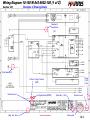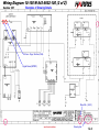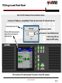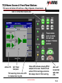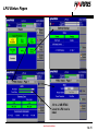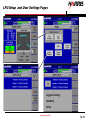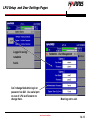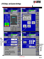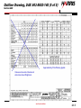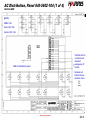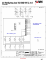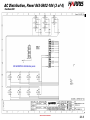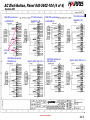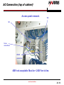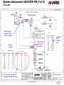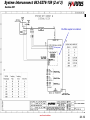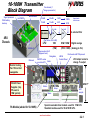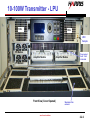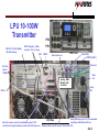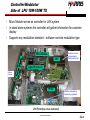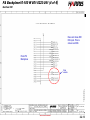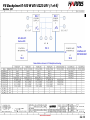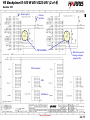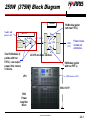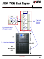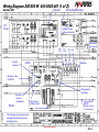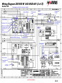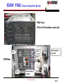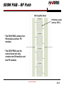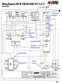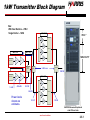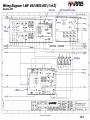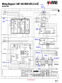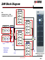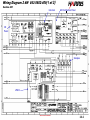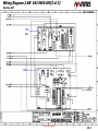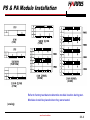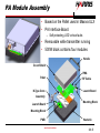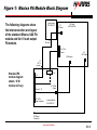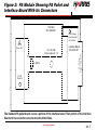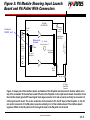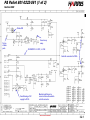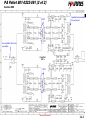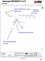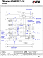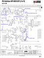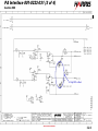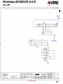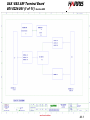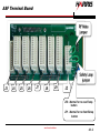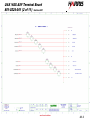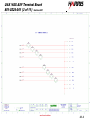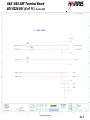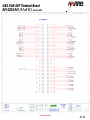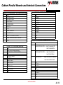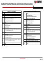
1
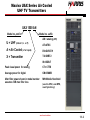
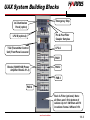
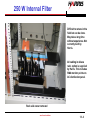
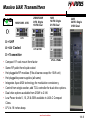
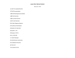
Welcome to Harris Broadcast Maxiva UAX UHF Air Cooled Transmitters Presented by: Harris Training Department 1 kW ATSC or COFDM, 1.5 kW Analog next level solutions 1-1.1 Maxiva UAX Series Air Cooled UHF TV Transmitters UAX 1500 AN Model no. suffix Model no. prefix U = UHF (others V, L AN = analog (ATV) or F) AT=ATSC A = Air Cooled (L for liquid) DV=DVB-T/H X = Transmitter T2=DVBT2 IS=ISDB-T Peak visual power for analog CT= CTTB Average power for digital CM=CMMB After filter power shown in model number assumes 1dB max filter loss MH=Mobile Handheld (used in ATSC, was MPH, need Synchrony) next level solutions 1-1.2 UAX System Building Blocks Emergency Stop AC Distribution Panel (option) Pre & Post Filter Coupler Samples LPU B (optional) LPU A TCU (Transmitter Control Unit) Front Panel Lowered PAB 1 Blocks) 500W PAB (Power Amplifier Blocks # 1-4) PAB 2 PAB 3 PAB 4 Rack & Filter (optional) Note: all filters won’t fit in bottom of cabinet. Up to 1 kW filters will fit in cabinet. Some 2 kW won’t fit. next level solutions 1-1.3 250 W Internal Filter Difficult to retune in the field but can be done. May take a long time without experience. Not currently built by Harris. All cabling in deluxe rack option is supplied by Harris. This includes SMA monitor points on AC distribution panel. Rack side cover removed next level solutions 1-1.4 Maxiva UAX Transmitters R okHS 10W/100W 4 RU 250W/500W 9 RU Single 16 RU Dual 1kW 14 RU Single 21 RU Dual 2kW 24 RU Single 31RU Dual LPU U = UHF A = Air Cooled LPU & PAB X = Transmitter LPU & 2 PABs • • • • • • • • Compact 19” rack mount form factor Same RF pallet from liquid cooled Hot pluggable RF modules (PAs all same except for 10W unit) Hot pluggable power supplies (all same) Integrates Apex M2X technology for modulation consistency Control from single exciter, add TCU controller for dual drive options. Dual drive options available from 250W to 2 kW Low Power levels 5, 10, 25 & 50W available in UAX-C Compact Class. • LPU is 18 inches deep. next level solutions 1-1.5 Maxiva UAX– Power Supply Up to 100W at 110VAC - 250W & above 208VAC • • • • • • • Universal input 100–240 VAC 50/60HZ High-efficiency auto ranging design Good power factor (>0.98, nominal-very efficient) Power supply efficiency ~90% Low AC line harmonics Mounted on slides, hot pluggable through front of transmitter One power supply per PA module for high reliability LPU = Low Power Unit Power Supply Module next level solutions 1-1.6 Maxiva UAX PA Module Weight: ~ 2.3 kg (5.1 pounds) • Two 90 Watt digital RF amplifiers (FET’s) per module • 180 watts (avg.) normal digital operation (90W + 90W). Approx. 20dB gain per FET. 17-19 dB overall gain for module. FET2 • Lightweight, hot-pluggable and interchangeable FET1 • Two LDMOS (FET) devices per module • 500W PA block weighs 69lbs including modules. • • Broadband UHF – Band IV & Vt Test fixture needed to rebias FETs if replaced individually. next level solutions UAX PA Module (cover removed) PA Interface Board 1-1.7 Maxiva UAX– Operating Voltages • Standalone = Rack w/o AC dist. Panel or no rack. Just components up to 1 kW. • LPU Power Levels up to 100W digital (150W analog, peak of sync with 10% aural): Single Phase, 110-240VAC, 50 or 60Hz, one IEC C15 and one IEC C20 (16 amp rating in Europe) AC input connector. • Tx Power Levels 250W digital to 3000W (analog): Single Phase, 208-240VAC, 50 or 60Hz, one IEC C15 and one IEC C20 AC inlet connector for LPU’s and dual IEC C20 AC inlet connectors for each PAB (power amplifier block) chassis. • Check voltage at plugs 1 at a time before initial turn on. LPU Rear Dual PAB Rear Don’t stress cables during installation. next level solutions 1-1.8 Maxiva UAX– Operating Voltages • Transmitters are configurable on-site for single or three phase AC connection. Loads are split to keep max components on line if phase is lost. • If three phase power is used then supply voltage (per phase) must be between 110 & 240VAC for LPU and 208240VAC for PAB’s. • Single phase 208 VAC ok with large breaker. • An optional in-rack AC distribution chassis (Deluxe Rack) provides individual circuit breaker protection for each AC input. AC distribution panel not included in Basic Rack. • Refer to the wiring diagram, AC distribution drawing 8435602-104 for more detail. next level solutions 1-1.9 UAX Power Levels Model Numbers Configuration Single LPU Systems PA & PS Modules Analog 4RU LPU 1 4RU LPU Output Power Digital Analog (pk.) Digital (avg.) Output UAX 15AN UAX 10* 15 W 10 W N 2 UAX 75AN UAX 50* 75 W 50 W N 4RU LPU 2 UAX 150AN UAX 100* 150 W 100 W N 4RU LPU (1) 5RU PAB 2 2 UAX 375AN UAX 250* 375 W 250 W 7/16 DIN 4RU LPU (1) 5RU PAB 2 4 UAX 750AN UAX 500* 750 W 500 W 7/16 DIN 4RU LPU (2) 5RU PAB 2 8 UAX 1500AN UAX 1000* 1.5 kW 1 kW 7/16 DIN 4RU LPU (4) 5RU PAB 2 16 UAX 3000AN UAX 2000* 3.0 kW 2 kW 1-5/8 Rigid * DV = DVB-T * IS = ISDB-Tb *FL = FLO *AT = ATSC Coupler output is 7/16 Din Up to 8 kW models available. Notes: Digital power levels are average power at the output of mask *CM = CMMB filter. 1 dB filter loss assumed. *CT = CTTB Analog power levels are peak sync power at the band pass *MH = ATSC Mobile Handheld (IMD) filter output. *T2=DVBT2 next level solutions 1-1.10 Maxiva UAX Block Diagram next level solutions 1-1.11 UAX Documentation Package 988-2693-004 UAX Documentation Package Contains: Technical Manual 888-2693-004 (English) Drawing Package 943-5276-170 Note: Manuals available in Portuguese (005) and Chinese (002) next level solutions 1-2.1 843-5276-170 Cover Sheet Page 1 of Drawing Package next level solutions 1-2.2 Wiring Diagram 10-100 W 843-5602-100 (1 of 2) Section 100 Examples of Drawing Details Number of Conductors (8/) Wire Number (3) Dwg. Vert. Axis To/From - Page / Section (2/D8) Revision Level Dwg. Hor. Axis Signal Name (INTRFC) next level solutions Sheet No. ( 1of 2 ) Revision Level Drawing No. 1-2.3 Wiring Diagram 10-100 W 843-5602-100 (2 of 2) Section 100 Examples of Drawing Details To/From - Page / Section (1/A6) Signal Name (INTRFC) Sheet No. ( 2of 2 ) next level solutions Drawing No. 1-2.4 TCU Log in and Front Panel Set or find IP address in Service>Netwrk screen Connect to IP address - using Mozilla Firefox for best results. IE 8 should work too. 15 minute timeout on TCU Username = admin PC runs LINUX. Improvements to come will increase speed and responsiveness. Password = harris2009 (remote) = harris (local GUI on older non-PPC units) TCU controls LPU switching and TX system in dual LPU systems. next level solutions 1-3.1 TCU Home Screen & Front Panel Buttons TCU users not limited. LPU will have 2 Eng, 2 Operator, 2 Guest levels. Auto is normal. Man disables ALC. These buttons work on remote GUI with web browser if Remote enabled. Active LPU GUI Panel Computer TCU event log. Go to active LPU for detailed fault log info. Yellow LED indicates missing RTAC sample in this case. Need to check active LPU for warnings and errors. Not always listed in TCU event log. next level solutions Auto can’t be selected with a bad LPU. 1-3.2 LPU Coaxial Switch • Pins 1, 2 and 3 are used for LPU switching. Pin 2 has +12 V applied to it (comes from TCU, marked COM on the relay box). • Pins 1 and 3 normally have 12 V applied (via pin 2) but either 1 or 3 are grounded briefly to make the switch change positions. Measuring 12 V between case and pins 1, 2 & 3 is normal except during a switch. • The relay will switch manually if you ground pins 1 or 3 to the case with a screwdriver - 6 7 Top View. Looking down from rear of transmitter. +12 3 - 5 1 2 LPU B Load 96 89 Same view as above. Coax Connectors GND 90 2 97 LPU A Splitter Pins 5, 6 & 7 are used for status. Pin 6 is ground. Depending on switch position Pin 6 connects to either pin 5 or pin 7 to send a ground indication (status) back to the TCU. The pin not grounded will measure 12V. next level solutions 1-3.3 TCU Home Screen, Event Log, & System Service 1x set up at factory next level solutions 1-3.4 TCU Screens System Service, Network, SNMP, NTP Set by SNMP user. Watch for leading spaces. Only support versions 1 &2C at this time. Simple network management protocol. Use with MIBs to control system. Trap monitor used in networks, CS Navigator management system. LPU takes only one NTP address. next level solutions Network time protocol. Time references from network locations. 1-3.5 TCU Screens System Service, Configuration & Version Refer to these screens when working with Harris field service. These may change with PCM update These Config settings go out LPU’s. See details on next slide. next level solutions 1-3.6 TCU System Service, Configuration Reflected power that will initiate foldback (1-4%). 4% is around 1.5:1 VSWR How far will Tx foldback 50-100%. 100% foldback = zero watts output How long Tx stay in foldback 5 - 120 seconds. Tries to increase power in 20% increments. Level of low power output warning – yellow bar. 80% typ. Level of high power output warning – red bar Sets 100% power output level on bar Power setting in active LPU. May be lower than Fwd Power Ref. if bad module or in foldback. Set desired TPO (W) here. Set desired TPO % here (0-100%). Limited by Nominal Power Out next level solutions 1-3.7 TCU System Update PCM software is upgradeable using the System Update screen. Microprocessor may need to be changed for some updates. MCM updates via flash card. Browse for .tcu filename and select. Press Load File button to upload file to TCU. Bar will turn green and read 100% when file is loaded. Press Update Now to update PCM…or press Remove File to cancel the process. next level solutions 1-3.8 TCU Software Components 861-1142-012 (861-1142-082 FLO) UAX SW, Customer I_O (JTAG, XYLINX programmer needed) 861-1142-022 (861-1142-102 FLO) UAX SW, UCP, Main Control Module (.ace file on flash card, must rename old file extension .old) 861-1142-092 (961-1142-112 FLO) UAX SW, UCP, Process Control Module (.tcu file used in Program Update) 861-1142-142 (861-1142-122 FLO) UAX SW, UCP, TCU Interface (JTAG, XYLINX programmer needed) 861-1142-052 (861-1142-132 FLO) SW, UCP, Panel PC (LINUX and flash card in panel pc, use hook to remove and replace flash card) Note: The PCM software is the only TCU software upgradeable via ISP & the web GUI. MCM may also be upgradeable via ISP in the future. next level solutions 1-3.9 LPU Screens TCU Home screen Tx OFF. Exciter A selected. Pressing the exciter button on LPUA opens the LPU log in screen. Username = admin No login = Guest Mode Password = admin These are setup on the LPU using NetAdmin. next level solutions UAX Home screen opens after log-in. 1-4.1 LPU Screens TCU tab LPU tab Firefox browser allows multiple tabs. next level solutions 1-4.2 LPU Screens TCU Screen next level solutions 1-4.3 LPU Screens All fans in PAB run at same speeds. PAB fans can be changed while onair. PA module temp max is 90oC. Warning at 115oC. No ambient temp trip point. FET current Id1 & 2 max 14A next level solutions 1-4.4 LPU Exciter Home and RTAC Screens Post RTAC output after mask filter. Signal doesn’t immediately disappear if signal is lost. Successes Attempts Pressing the RTAC box on the Exciter Home page opens the RTAC control screen. Linear corrects for distortions in filter. Nonlinear corrects for distortions in amplifier. next level solutions 1-4.5 LPU Exciter Home and Fault Log Screens Pressing the Fault Log button opens Fault Log-All Faults screen. Erases all log entries. Active faults will come back. Displays only active faults. All faults will return if pressed again. next level solutions 1-4.6 LPU Status Pages Save Page As and email to service. next level solutions 1-4.7 LPU Status Pages Holdover = time remaining till shutdown if GPS is lost. next level solutions 1-4.8 LPU Status Pages Build Version should appear as shown (part # REV#). If the LPU does not have all the proper software revisions installed for a particular build then “Customer Special” will be displayed. The full build should be installed when updating software. The full build contains all matching software components. next level solutions 1-4.9 LPU Status Pages C.1 added resistor to board. Expansion board used for DVBT-2. next level solutions 1-4.10 LPU Status Pages -10 to -2 dB RTAC Level to LPU rear is ideal next level solutions 1-4.11 LPU Setup and User Settings Pages Logged in using: netadmin harris next level solutions 1-4.12 LPU Setup and User Settings Pages Logged in using: netadmin harris Can’t change NetAdmin login or password via GUI. Use serial port on rear of LPU and Teraterm to change them. Must log out to exit. next level solutions 1-4.13 LPU Setup and System Settings Main header for each LPU page Time Server Settings: None GPS NTP Feature key must be changed as options are added. Contact Harris Sales. To change feature key Unlock, enter new key, wait 30 seconds and reset via ISP. next level solutions 1-4.14 LPU Setup and Transmitter I/O, PRFU Set new frequency here if no TCU. New F requires Cal. Only GPS & 1PPS in SFN. Disc. Ref. used in Manual mode only. next level solutions Yes best. 1-4.15 LPU Setup and Remote Communications Set for LPU A. LPU B uses .3 IP Need front MAC address for new feature key. Can’t be set same on both LPU’s. Will cause LPU’s to cycle ON/OF. next level solutions 1-4.16 LPU Setup ATSC Modulator Screens Present for MH only. Next Page next level solutions 1-4.17 LPU Setup ATSC Modulator Screens Present for MH only. next level solutions 1-4.18 LPU Setup ATSC Modulator Screens next level solutions 1-4.19 Outiline Drawing, UAX 843-5602-148 (1 of 5) Section 800 Harris can supply basic rack. Dims in millimeters. 37 ” deep rack will work. N to 7/16 Din with coupler. Aluminum pieces on PAB slide into rack fixture for support. next level solutions Dipswitch set for PAB location. 2-1.1 Outiline Drawing, UAX 843-5602-148 (2 of 5) Section 800 PA modules protect themselves. No protection on backplanes. Could be stand alone but rack recommended. Output 1 goes to PA2. Output 2 goes to PA1. 952-9248-072 PA bypass cable. Used to keep operating with removed PAB. Reject loads only good for 500W. Labeled as 1.2 to 1.6kW. All are the same. Can’t do a cal if PA module or PAB is faulted. 2kW standalone not recommended. next level solutions 2-1.2 Outiline Drawing, UAX 843-5602-148 (3 of 5) Section 800 Dims with back door open. Approx. 100W LPU output for 2kW unit. Deluxe rack configuration. next level solutions 2-1.3 Outiline Drawing, UAX 843-5602-148 (4 of 5) Section 800 Air out. 1-5/8” out for 2 kW. 7/16 DIN for 250-1kW out. Customer supplied plenum (hood) can go above opening. Back door would be solid in that case. Air in. next level solutions 2-1.4 Outiline Drawing, UAX 843-5602-148 (5 of 5) Section 800 Approximately 18% efficiency typical. Values not accurate. Breakers & wire sizes close. Weights ok. next level solutions 2-1.5 AC Distribution, Panel 843-5602-104 (1 of 4) Section 800 @208V: PAB’s 7-8A. Active LPU <5A. Inactive LPU < 2A. VAX has built in contactor and standard emergency off button. 2kW AC distribution panel. Optional red button. Breaks interlock chain. next level solutions 2-1.6 AC Distribution, Panel 843-5602-104 (2 of 4) Section 800 Same breakers as in 2 kW but some not used. 1kW AC distribution panel. Optional Red button. next level solutions 2-1.7 AC Distribution, Panel 843-5602-104 (3 of 4) Section 800 250 & 500W AC distribution panel. next level solutions 2-1.8 AC Distribution, Panel 843-5602-104 (4 of 4) Section 800 208V WYE w/o Neutral 1Ph 380V w Neutral 208V WYE w/o Neutral 1 Ph 380V w Neutral or 240V DELTA (208-240V L1-N) or 240V DELTA (208-240V L1-N) AC from UPS 380V WYE with Neutral (208-240V L-N) Split Ph, 208V -240V L1-L2 380V WYE with Neutral (208-240V L-N) next level solutions Split Ph, 208V -240V L1-L2 2-1.9 AC Connection (top of cabinet) Access panel removed. TB2 TB1 Screw connections WAGO connectons 480V not acceptable. Must be < 240V line to line. next level solutions 2-1.10 System Interconnect 843-5276-159 (1 of 3) Section 800 Always supplied. Output coupler optional. Can be 15/8 or 7/16 fittings. 7/16 DIN if Harris couplers used. Should be on connector B pins 2 & 8. Interntal Coupling LPU Use pad values on wiring diagrams 843-5602-400 to 412. next level solutions 2-1.11 System Interconnect 843-5276-159 (2 of 3) Section 800 Pre-filter coupler is in cabinet. To front panel next level solutions 2-1.12 System Interconnect 843-5276-159 (3 of 3) Section 800 next level solutions 2-1.13 10-100W Transmitter Block Diagram Signal processor Expansion Card for DVBT2 Micromodule PS & battery backup On channel (1 stage upconverter) 70 mW 25 mW 1.6 W 100 W 70 mW 13 mW .8 W 50 W 18 dB PA Modulator 4RU Chassis Approximate levels shown. 18 dB To external filter PA (Pad Varies 6 or 9 dB) LPU 140 Mhz IF Ethernet Digital average 10W 50W / 100W (15W) (75W / 150W) (Analog pk. Vis) Upconverter (ALC happens here) Navigation ON/OFF works Enter on active LPU LED & Control Panel Don’t work with TCU present LPU output varies to change Tx output Exciter Cooling Fan 12V not hot swappable. 50 Volt Power Supplies (top PS used in 10W system) PA Module (added for 50-100W) 4RU=7” Status Setup Home UDC sample Special cascaded driver module used for 10W LPU. Standard module used for 50 & 100 W LPU. next level solutions 2-2.1 10-100W Transmitter - LPU FAN FAN UDC Sample PS Module Amplifier Module Amplifier Module Overcurrent fault >14A is latched PS Module Front View (Cover Opened) next level solutions Washable filter material 2-2.2 LPU 10-100W Transmitter UDC Out 75 mW (digital) 150 mW (analog) PS2 RTAC Samples -5 dBm nominal, -10 to -2 range CAN PA2 PS1 RS232 ASI monitor out ASI (ATSC) SMPTE (ATSC) Ethernet Ref. Out 1pps & 10 MHz Analog, DAB Module, ASI reclocker GPS In Used for remote control in standalone system. TCU control in dual system. Remove cable and LPU takes over. LPU Front PA1 Mod. AC Amp. AC Safety Interlock pins 2 & 8. On command reactivates. Kills RF and DC too. Ribbon cable removal doesn’t affect other LPU next level solutions LPU Rear 2-2.3 Controller/Modulator Side of LPU 10W-100W TX • • • Micro Module serves as controller for UAX system In stand alone systems the controller will gather information for customer display Supports any modulation standard – software controls modulation type Micro Module Down Up UDC FPGA Remove cover to replace board. Don’t touch pots. Signal Processor Battery Backup PFRU GPS Rx (activated by feature key (optional). LPU Front (top cover removed) next level solutions 2-2.4 Optional Battery Backup The battery backup keeps the GPS receiver, 10 MHz OCXO and associated PFRU circuitry alive for approximately 15 minutes* during a power failure. Currently under development is a replacement that will keep the UDC operating for 15 minutes and the PFRU and GPS alive disciplined for 45 minutes. This is to ensure that when power is restored, the operator does not have to wait for a GPS re-acquisition or the oscillator to warm back up and re-stabilize. Saves time on restart. Operation of this circuitry and battery backup option are recommended for SFN installations. *When batteries are new and fresh. These batteries should be considered a routine maintenance item and replaced at appropriate intervals. Replacement every year is recommended. next level solutions 2-2.5 10W Transmitter Model 25 - 100 mW out of modulator padded to 3 mW. Pad may vary with channel. 18 dB UDC (power adjusted here) 10 W 150 mW 18 dB Modified Driver PA Module (2 FET’s) Special driver module (cascade) used for 10W LPU. Standard module used for 50 & 100 W LPU. Second PA Module added for 50 & 100W LPU’s Power and gain levels given are estimates only. next level solutions 2-2.6 Wiring Diagram 10-100 W 843-5602-100 (1 of 2) Section 100 Keeps GPS & PFRU running for 15 mins. Comm & LCD control Used for ATSC or DAB only. Supplies voltage to all boards in UDC. LVPS Distribution board Signal Processing board Analog Option PFRU All settings stored here. Front Panel Obsolete RS485 F varies with modulation. PLL lock App. 100 MHz indicator IF or DAC LO. on front comes from here Up/Down Converter TX I/O Interface Micro=heart of system 140 MHz LO jumper RTAC samples Rx Option RF out Outuput 140MHz above or below channel. RF sample. Turn off RTAC to measure good signal here. GPS from antenna Rear of chassis Use Upload Config Fle to restore settings in SPB. next level solutions 2-2.7 Top View LPU LVPS Distribution board UPS batteries Date/Time Battery PFRU board Transport Stream Inputs Signal Processior board Application microprocessor Front Panel TX I/O Interface GPS Rx RF Up/Down Converter PLL DAC Converter Down Converter RF Out (SMA) LO Filter next level solutions Up Converter 2-2.8 Wiring Diagram 10-100 W 843-5602-100 (2 of 2) Section 100 PAs plug in here. PA1 PA2 To front panel board. RS485, Fwd & Ref. Pwr. 50V PA Distribution board Fan Filter board 50V PS Distribution board Edge connector 10W Control/Monitor board. Controls master/slave. 2nd part of control system used in LPUs and PABs. Collects data from 2 PAs Reflected not used. Coupler Detector Detectors Connector. Not signal flow. 50V fans next level solutions 50/ 100W From Exc. 2-2.9 PA Backplane10-100 W 801-0223-041 (1 of 4) Section 100 Sheet 3 top From PS2 From PS1 Sh 2 J1 J2 Sh 2 Sh 4 Sh 3 J5 J6 Trigger off this to see. Signals multiplexed back to controller. To PS interface J3 Used in PA Blocks Not used. next level solutions 2-2.10 PA Backplane10-100 W 801-0223-041 (2 of 4) Section 100 If PA not installed PS won’t come on. Interlock here goes back to PS (first to break last to mate) J1 J2 From Sh 3 SMA SMA 10W amp interlock Muxed data cables. next level solutions 2-2.11 PA Backplane10-100 W 801-0223-041 (3 of 4) Section 100 J1 Fan Filter Board J3 Digital Control Lines next level solutions 2-2.12 PA Backplane10-100 W 801-0223-041 (4 of 4) Section 100 Does not show 50V DC input. This is shown on 3/D6 From PS Backplane Chip selects next level solutions 2-2.13 PS Backplane10-100 W 801-0223-051 (1 of 4) Section 100 Sh 2 Sh 2 J2 J1 801-0223-071 Section 500 J1 To PA interface J5 801-0223-041 Sh 2 J5 Sh 3 Sh 4 Same table as shown in PA backplane drawing. next level solutions 2-2.14 PS Backplane10-100 W 801-0223-051 (2 of 4) Section 100 Goes to jack 2. Pulls up fault line. Not installed. Was to be used to change voltages going to PAs. PS Connectors. +50V +50V Return next level solutions 2-2.15 PS Backplane10-100 W 801-0223-051 (3 of 4) Section 100 next level solutions 2-2.16 PS Backplane10-100 W 801-0223-051 (4 of 4) Section 100 Does not show +50V dc outputs. They are shown on 2/A1 & 2A5. next level solutions 2-2.17 250W (375W) Block Diagram 5 RU PAB 75 mW & 9dB pad to 2 mW PA Module (pallet with two FET’s) 4RU LPU Full Pallet 95 mW Exciter / Cont Driver 6W PA 5.8 W Splitter 2.4W 150W Combiner 250W (375) Full Pallet Two PA Modules (2 pallets with two FET’s). Low output power, little chance of failure. Power levels shown are estimates. All 4 PA modules identical. PA Module (pallet with two FET’s) LPU 100W version of LPU 9RU=15.75” PAB Power Amplifier Block next level solutions 2-3.1 500W (750W) Block Diagram 5 U PAB Full Pallet 4RU LPU 3 mW Exciter / Cont 12 W 190 mW Driver PA 11.5 W Full Pallet Splitter 500 W Combiner Full Pallet Power levels shown are estimates. Full Pallet PS or amp pallet failure in LPU causes no output. 2.4W each 150W each LPU Pout = (# good amps/total # amps)2 9RU=15.75” PAB Power Amplifier Block next level solutions 2-3.2 Wiring Diagram 250/500 W 843-5602-401 (1 of 2) Section 200 Interlock I/O Panel AC Distribution Panel Optional. Same action as interlock. Post RTAC Contact closures LPU B Pre RTAC Varies if filter out of cabinet. REF FWD Samples Don’t go to top of cabinet. Only present in analog. Remote here for standalone RF Out Coax runs on outside of unit. Amp control board Interlock, RS485, ON/OFF, Restrike, 12V line to TCU not used. The following are interconnection drawings that show the system building blocks. next level solutions 2-3.3 Wiring Diagram 250/500 W 843-5602-401 (2 of 2) Section 200 Unplugging one exciter causes exc switch. Interface Module 2nd PS optional in TCU LPU Switch Normally not needed. .2 .3 TCU Rear W/12 V applied pin can be shorted to cause switch. IP address +:592 CAN, set up on Remote Com setup screen. Loss causes exc. Switch. PAB 1 IP 192.168.2. 100 Controls LPU switch. Not for VT100. For eng. Customer I/O Coupler 1 Coupler 2 Filter Amp. Control Same RS485 ID as LPU B LPU A next level solutions 2-3.4 500W PAB (Power Amplifier Block) PAB Front (Filter & PA modules removed) Fan 2 Fan 1 AC Inputs A and B Fan 4 PAB Rear Fan 3 Goes to top of cabinet. next level solutions 2-4.1 500W PAB – Front View AC OK 50V OK 50V PS Fault (AC,DC, Temp) Splitter behind here. Power Supply Power Supply Power Amplifier Power Amplifier Combiner behind modules. Power Supply Power Amplifier Power Amplifier Power Supply next level solutions 2-4.2 PS & Module – LED’s 1 2 3 LEDs self contained on modules. 7 6 5 4. 5. 6. 7. PA under voltage = <46V 5 PA over voltage > 53V PA temperature fault 85o C PA Overcurrent > 14A 4 Summary info green or amber (not red) Front of PA Module Front of PAB (also called HPU) Push or pull here to avoid bending handle. Front of PS Modules next level solutions 2-4.3 500W PAB- Top View Fans Fan filter board 901-0223-071 (same on LPU) Combiner Power Supply Splitter Ouputs: all same printed wire number. Hand written numbers are accurate. Pt. no. corresponds to jack number on diagram. Front of PAB next level solutions 2-4.4 500W PAB- Top View Control Monitor (amp interface) Board 9010223-071 PS Backplane Rotary Switch – Cabinet ID (tells RS485 which PAB it is) See 2-12 in manual. PA Backplane Check push on spade lugs for tightness. Alarm status board 9010223-081 also called LED Board on the front of the PAB chassis. Front of PAB next level solutions 2-4.5 500W PAB – RF Path PA Module (pallet with two FET’s) • The 500 W PAB contains four PA modules and four PS modules. • The 250 W PAB uses the same chassis but only contains two PA modules and two PS modules next level solutions 2-4.6 Wiring Diagram 500 W PAB 843-5602-101 (1 of 1) Section 200 PA4 4 way splitter (500W) PA3 Power Supply Backplane PS (4) PA2 PA1 PA Distribution board (backplane) 2 way splitter (250W) Control & Monitoring board Fan Filter board 50V Fans (4) Rear panel connectors. AC Filters next level solutions Ground 2-4.7 1kW Transmitter Block Diagram Size: With Dual Exciters – 21RU Single Exciter – 14RU 5 RU PAB 7RU= ” Full Pallet Full Pallet Splitter 3RU TCU 4RU LPU Combiner Full Pallet 14RU=29.75” Full Pallet Exciter / Cont Driver PA Exciter Switcher 4RU LPU .3 dB Loss Splitter Combiner 1000 W Exciter / Cont Driver 5RU PAB PA Full Pallet 7 mW 450 mW 28.3 W Full Pallet 26.4 W Power levels shown are estimates. Splitter Combiner Full Pallet 12.3 W Full Pallet 536 W UAX1000 shown with optional dual LPU and rack next level solutions 2-5.1 Wiring Diagram 1 kW 843-5602-405 (1 of 2) Section 300 Interlock AC Distribution Panel I/O Panel Samples LPU B next level solutions 2-5.2 Wiring Diagram 1 kW 843-5602-405 (2 of 2) Section 300 LPU Switch TCU Rear PAB 1 PAB 2 Coupler 1 Combiner Filter Coupler 2 LPU A Reject Load next level solutions 2-5.3 2kW Block Diagram 5RU PAB Size: With Dual Exciters – 31RU Single Exciter – 24RU = 47.25” Full Pallet Full Pallet Splitter Combiner Full Pallet 5RU PAB Full Pallet Full Pallet 3RU TCU 4RU LPU Full Pallet Splitter Exciter / Cont Driver Combiner Full Pallet PA 5RU HPU Full Pallet Exciter Switcher 4RU LPU Full Pallet Splitter Full Pallet Exciter / Cont Driver PA Splitter 2k W Combiner Combiner Full Pallet 14 mW 900 mW 5RU PAB 56 W Full Pallet Full Pallet 53 W Power levels shown are estimates. Full Pallet Splitter Combiner Full Pallet 12.3 W 535 W Full Pallet next level solutions UAX2000 shown with optional dual LPU and rack 2-6.1 Wiring Diagram 2 kW 843-5602-409(1 of 3) Section 400 Interlock AC Distribution Panel I/O Panel Samples LPU B next level solutions 2-6.2 Wiring Diagram 2 kW 843-5602-409(2 of 3) Section 400 TCU Rear LPU A next level solutions 2-6.3 Wiring Diagram 2 kW 843-5602-409(3 of 3) Section 400 Combiner PAB 1 LPU switcher PAB 2 Splitter 4 Way Reject Loads Load must be present . Coupler 1 Filter PAB 3 Final Combiner Combiner May not be ribbon cable in new models. PAB 4 1-5/8 rigid Coupler 2 (in cabinet if filter is) To TCU at top of cabinet. Filter may be internal or external. next level solutions 2-6.4 Maxiva UAX PA Module • Two 90 Watt digital RF amplifiers (FET’s) per module • 180 watts (avg.) normal digital operation (90W + 90W). 700900W peak power per FET. • Lightweight, hot-pluggable and interchangeable • Two LDMOS (FET) devices per module • Weight: ~ 2.3 kg (5.1 pounds) FET2 FET1 UAX PA Module (cover removed) Broadband UHF – Band IV & V next level solutions 3-1.1 PA Module RF Input RF Out PS Interlock Edge connector Heat sink fins UAX PA Module Rear See page 2-6 in manual to see modules in PAB. next level solutions 3-1.2 PA Module Handle – Pull on outside edges. Current 7 (>14 A) Temperature 6 (85oC) 7-8 amps normal Pallet temp Over voltage 5 (>53V) Under voltage 4 (<46V) Front LED’s (LED numbers refer to table on another slide) These trigger a hard fault when active. Faults are prioritized to deliver only 1 fault at a time. The faults latch after 3 strikes. Faults feed back to GUI. next level solutions 3-1.3 PS & PA Module Installation (15W) (750W) (75W/150W) (1500W) (3000W) (375W) Refer to factory test data to determine module location during test. Modules should be placed where they were tested. (analog) next level solutions 3-1.4 PA Module Assembly • • Based on the Pallet used in Maxiva ULX PA Interface Board – Self protecting, LED’s show faults • • Removable while transmitter running 500W block contains four modules Handle Cover/Shield PWA Pallet N-Type Conn RF Cable Launch Board Assembly Launch Board Mounting Block Mounting Block PWB next level solutions Heatsink 3-1.5 Figure 1: Maxiva PA Module Block Diagram Input Launch 801-0222-011 The following diagrams show the interconnection and layout of the standard Maxiva UAX PA module and the 10 watt output PA module. E1 RF Input PA Pallet 801-0222-081 J2 RF Input J1, 20 Pin, Control 50Vdc Input E2 RF Output J6 RF to Launch Standard PA module diagram shown. 10 W module will vary. J1 20 Pin J3-C RF Input E1 50Vdc Output J3 pins 9 - 13 +50 Vdc Input J3, 36 Pin Edge Connector Interface Board 801-0223-031 RF Output Connector next level solutions 3-1.6 Figure 2: PA Module Showing PA Pallet and Interface Board With Its Connectors PA Pallet 801-0222-081 J4, RF Output From This Half of PA Pallet E1, +50 Vdc From J3 pins 9 - 13 J1, 20Pin Interface Board 801-0223-031 J3, 36 Pin Edge Connector J6, RF From J3-C J5, RF From J4 The standard PA pallet board covers a portion of the interface board. That portion of the interface board and its connectors are shown with dotted lines. next level solutions 3-1.7 Figure 3: PA Module Showing Input Launch Board and PA Pallet With Connectors PA Pallet 801-0222-081 J4, RF Output From This Half of PA Pallet E1, RF Input J2, RF From J6 Bottom side of board. Input Launch 801-0222 -011 J1, RF From J5 Interface Board 801-0223-031 E1, +50 Vdc From J3 pins 9 - 13 J1, 20Pin HY1, Input 3dB Hybrid HY1, Output 3dB Hybrid J3, 36 Pin Edge Connector PA turned ON/OFF via J1 E2, RF Output RF Output Blind Mate Connector Figure 3 shows part of the interface board, and details of the PA pallet and input launch boards, which sit on top of the remainder of the interface board. RF enters the PA pallet via the input launch board. Connector J6 on the interface board gets its RF input signal from edge connector J3-C and connects vertically to connector J2 of the input launch board. The center conductor of J2 connects to E1, the RF input of the PA pallet. J1, the 20 pin control connector of the PA pallet, connects vertically to J1 of the interface board. The interface board supplies +50Vdc to the PA pallet via E1, through the hole in the PA pallet circuit board. next level solutions 3-1.8 Figure 4: Maxiva 10 Watt PA Module Block Diagram (Halves of One PA Module Cascaded) J2 RF Input Input Launch Board 801-0222-011 3 pin jumper here enables PA on. E1 RF Input 1/2 PA Pallet 1/2 PA Pallet Output Cascade Launch Board Copper strap E In, RF Input 1/2 PA Pallet J1 RF Input 1/2 PA Pallet Part of Input Launch Board E2 RF Output J1, 20 Pin, Control J6, RF to Launch 50Vdc Input J4 PA Pallet 801-0222-081 J5 J1 20 Pin J3-C RF Input J3 pins 9 - 13 E1 50Vdc Output Won’t work in a standard module slot. +50 Vdc Input J3, 36 Pin Edge Connector Interface Board 801-0223-031 In Figures 4 & 5, the PA module in the 10W Maxiva UAX transmitter consists of a standard PA module with the following changes: • The PA pallet input and output hybrids (HY1 and HY2) are removed. • The Output Cascade Launch board is added to the output of the first half of the PA pallet. • Jumpers are added to provide inputs and outputs for each half of the PA Module; • The output of the first half of the pallet is linked to the input of the second half of the PA pallet via interface board connectors J4 and J5. RF Output Connector next level solutions 3-1.9 Figure 5: 10 Watt PA Module Showing Input Launch, PA Pallet, and Output Cascade Launch Boards. Output Cascade Launch Board E1, RF Input 1/2 PA Pallet J2, RF From J6 E1, +50 Vdc From J3 pins 9 - 13 J3, 36 Pin Edge Connector Input Launch 801-0222 -011 RF Output 1/2 PA Pallet J1, 20Pin Interface Board 801-0223-031 1/2 PA Pallet EIn, RF Input 1/2 PA Pallet J1, RF From J5 E2, RF Output PA Pallet 801-0222-081 RF Output Blind Mate Connector next level solutions 3-1.10 PA Module RF Interconnect 843-5602-108 (1 of 1) Section 500 Used in 10 W model. Each half of PA pallet is in series (cascade), Used in all except 10 W model. Single sided version. Not used. next level solutions 3-1.11 PA Pallet 801-0222-081 (1 of 2) Section 500 Diode OR To top of bias pots. Goes to op amp. PA ON/OFF H = OFF, L = ON Sets idle currents for FETs. Conditioning of 5V supply to FETs Module test fixture to come in future. Needed to set idle currents. next level solutions 3-2.1 PA Pallet 801-0222-081 (2 of 2) Section 500 1 FET Symbol for transmission line on board. From splitter. Don’t mix up cables. Push Pull FET’s 1 FET next level solutions 3-2.2 Input Launch 801-0223-011 (1 of 1) Section 500 Used for 2nd half RF input of cascaded 10W PA modules. Gives same impedance as other leg. Approx. - 5 dB loss. Reflections go here to reject loads. RF Input for 10W and standard PA modules. next level solutions 3-2.3 PA Interface 801-0223-031 (1 of 4) Section 500 Rising edge trigger. Pulse Faults prioritized. Current first, then temp. ON command also clear command. From control system. Pulsed 3x if 3 strike applies. Tied together. LEDs may come on in varying numbers depending on state. ON button will turn them off. Decoder. Chip select. Edge card. Falling edge trigger. Faults clear first. next level solutions 3-2.4 PA Interface 801-0223-031 (2 of 4) Section 500 Upside down logic. HI= OK LO = Fault (in op amps this page or next) (10W amp.) Normally HI=OK. LO = Overcurrent Logic for cascade. Positive with PA current 2.5V 2.52V Only OFF or Red. next level solutions 3-2.5 PA Interface 801-0223-031 (3 of 4) Section 500 Only OFF or Red. next level solutions 3-2.6 PA Interface 801-0223-031 (4 of 4) Section 500 MUX output Chip select next level solutions 3-2.7 UAX /VAX ASF Terminal Board 801-0224-041 (1 of 11) Section 600 next level solutions 4-1.1 ASF Terminal Board J3 J4 J5 J6 J7 J8 J9 JP2 - Normal for no rear Estop button JP1 - Normal for no front Estop button next level solutions 4-1.2 UAX /VAX ASF Terminal Board 801-0224-041 (2 of 11) Section 600 next level solutions 4-1.3 UAX /VAX ASF Terminal Board 801-0224-041 (3 of 11) Section 600 next level solutions 4-1.4 UAX /VAX ASF Terminal Board 801-0224-041 (4 of 11) Section 600 next level solutions 4-1.5 UAX /VAX ASF Terminal Board 801-0224-041 (5 of 11) Section 600 next level solutions 4-1.6 UAX /VAX ASF Terminal Board 801-0224-041 (6 of 11) Section 600 next level solutions 4-1.7 UAX /VAX ASF Terminal Board 801-0224-041 (7 of 11) Section 600 next level solutions 4-1.8 UAX /VAX ASF Terminal Board 801-0224-041 (8 of 11) Section 600 next level solutions 4-1.9 UAX /VAX ASF Terminal Board 801-0224-041 (9 of 11) Section 600 next level solutions 4-1.10 UAX /VAX ASF Terminal Board 801-0224-041 (10 of 11) Section 600 next level solutions 4-1.11 UAX /VAX ASF Terminal Board 801-0224-041 (11 of 11) Section 600 next level solutions 4-1.12 Cabinet Parallel Remote and Interlock Connections Control 1 - J3 Top of Cabinet – 12 Pin Female (active low) GND 1 2 3 4 5 6 7 8 9 10 11 TRANSMITTER ON 12 GND 1 2 3 4 5 6 7 8 9 10 11 12 TRANSMITTER OFF RAISE POWER LOWER POWER RF MUTE GND SELECT DRIVE A SELECT DRIVE B SELECT AUTO DRIVE CONTROL SELECT MANUAL DRIVE CONTROL Control 2 - J4 - 12 Pin Female (active low) GND FUTURE 1 FUTURE 2 FUTURE 3 FUTURE 4 GND FUTURE 5 FUTURE 6 FUTURE 7 FUTURE 8 GND GND Status 1 – J6- 12 Pin Female 1 1 2 3 4 5 6 7 8 9 10 11 12 Control 3 – J5- 12 Pin Female (active low) GND SELECT AUTO POWER CONTROL SELECT MANUAL POWER CONTROL GND LOSS OF AC MAINS FUTURE 10 REMOTE CAN L REMOTE CAN H GND REMOTE CAN L REMOTE CAN H GND 2 3 4 5 6 7 8 9 10 11 12 TRANSMITTER ON STATUS : High: Transmitter Off Low: Transmitter On DRIVE A/B ACTIVE STATUS : DRIVE CONTROL: High: Drive A Active Low: Drive B Active High: Drive Control in Manual Low: Drive Control in Auto GND FUTURE 11 FUTURE 12 GND FUTURE 13 FUTURE 14 GND GND next level solutions 4-1.13 Cabinet Parallel Remote and Interlock Connections Status 2 – J7 – 12 Pin Female 1 2 4 5 6 7 8 9 GND REMOTE CONTROL ENABLED/DISABLED STATUS FUTURE 15 POWER CONTROL AUTO/MANUAL STATUS High: Power Control in Manual Low: Power Control in Auto GND RF MUTED High: RF Not Muted Low: RF Muted 1 2 3 VSWR FOLDBACK ACTIVE High: VSWR Foldback Not Active Low: VSWR Foldback Active GND VSWR FAULT High: VSWR Fault Not Active Low: VSWR Fault Active 4 5 6 7 POWER SUPPLY FAULT High: PS Fault Not Active Low: PS Fault Active 8 GND SUMMARY FAULT High: Summary Fault Not Active Low: Summary Fault Active CUSTOMER SUPPLIED VCC +30VDC MAX CUSTOMER SUPPLIED VCC +30VDC MAX GND 9 10 TRANSMITTER FAULTED OFF High: XMTR Not Off Due to Fault Low: XMTR Off Due to Fault 11 12 GND GND Status 3 – J8 – 12 Pin Female GND DRIVE CHAIN FAULT High: Drive Chain Fault Not Active Low: Drive Chain Fault Active PA FAULT High: PA Fault Not Active Low: PA Fault Active FUTURE 16 GND FUTURE 17 10 11 12 next level solutions 4-1.14 Cabinet Parallel Remote and Interlock Connections 1 2 3 4 5 6 7 8 9 10 11 12 Meters – J9 – 12 Pin Female FORWARD POWER REFLECTED POWER GND FUTURE ANALOG 1 FUTURE ANALOG 2 GND FUTURE ANALOG 3 FUTURE ANALOG 4 RS485 (+) FUTURE ANALOG 5 FUTURE ANALOG 6 GND next level solutions 4-1.15 LPU TX Interface Connector LPU TX Interface Connector - 25 Pin Male 1 2 3 4 5 Signal /Power Raise /Power Lower /TX On /TX Off Remote Control Command 6 /RF Mute Command 7 8 /Sum Fault /RF Mute Status 9 /UPS Shutdown 10 11 12 13 /EQ Reset /EQ Hold Not Used Not Used 14 /Exciter Active 15 16 17 18 19 20 21 22 23 24 25 /RF Present On/Off Status /Remote Fault Reset Auto/Manual Command /TCU Present Exciter/LPU Sum Flt Remote Enable\Disable GND GND GND GND Direction Input Input Input Input Input Input Description Power Raise Command Power Lower Command Transmitter On Command Transmitter Off Command Remote Control Command** RF mute command Output Output Input Summary Fault Status RF Mute Status Disables battery backup functionality Input Input Input Input Input Resets adaptive correction tables to default Holds current adaptive correction tables Output Output Input Input Input Output Output Indicates that the exciter is active (Master/Slave Mode for UAX)** Indicates that exciter RF output is valid Transmitter On/Off Status Restrike Command Auto/Manual Mode Command** TCU Present Command Exciter/LPU Summary Fault Status Remote Control Status Ground Ground Ground Ground Control I/O Assignment I/O Bus 0 I/O Bus 1 I/O Bus 2 I/O Bus 3 I/O Bus 4 Input directly to Signal Processing board I/O Bus 5 I/O Bus 6 Input directly to Signal Processing board I/O Bus 16 I/O Bus 7 Analog Input 0 Analog Input 1 I/O Bus 8 I/O Bus 9 I/O Bus 10 I/O Bus 11 I/O Bus 12 I/O Bus 13 I/O Bus 14 I/O Bus 15 This connector is on the rear of the LPU. It can be used for remote control and monitoring on standalone transmitters (non racked systems without TCU’s). next level solutions 4-1.16 LPU User Remote Connector Signal 1 2 3 4 5 6 7 8 9 10 11 12 13 14 15 16 17 18 19 20 21 22 23 24 25 Forward Power Reflected Power Spare Analog In 1 Spare Analog In 2 +12Vdc GND GND GND GND GND Alarm 0 Common Alarm 0 Normally Closed Alarm 0 Normally Open Alarm 1 Common Alarm 1 Normally Closed Alarm 1 Normally Open Alarm 2 Common Alarm 2 Normally Closed Alarm 2 Normally Open Alarm 3 Common Alarm 3 Normally Closed Alarm 3 Normally Open Alarm 4 Common Alarm 4 Normally Closed Alarm 4 Normally Open Direction Output Output Input Input Output User Remote - 25 Pin Female Description 0 – 4.096VDC output representing Forward power level 0 – 4.096VDC output representing reflected power level Control I/O Assignment Analog Output 0 Analog Output 1 Analog Input 2 Analog Input 3 +12Vdc, 200mA max Ground Ground Ground Ground Ground Alarm 0 Relay Common Alarm 0 Relay Normally Closed (Faulted) Position Alarm 0 Relay Normally Open (Non-Faulted) Position Alarm 1 Relay Common Alarm 1 Relay Normally Closed (Faulted) Position Alarm 1 Relay Normally Open (Non-Faulted) Position Alarm 2 Relay Common Alarm 2 Relay Normally Closed (Faulted) Position Alarm 2 Relay Normally Open (Non-Faulted) Position Alarm 3 Relay Common Alarm 3 Relay Normally Closed (Faulted) Position Alarm 3 Relay Normally Open (Non-Faulted) Position Alarm 4 Relay Common Alarm 4 Relay Normally Closed (Faulted) Position Alarm 4 Relay Normally Open (Non-Faulted) Position This connector is on the rear of the LPU. It can be used for remote control and monitoring on standalone transmitters (non racked systems without TCU’s). next level solutions 4-1.17 LPU TX Interface & User Remote Connectors Additional notes: ** The Remote Control, /Exciter Active, and Auto/Manual Commands are ignored when in Standalone operation. The UAX Transmitter will default to Standalone Mode when no connections are made to the Parallel I/O. If the /TCU Present signal is asserted at anytime, the Transmitter will be forced into Dual Mode for operations with a TCU. The Transmitter will remain in Dual Mode until power cycled with the /TCU Present signal de-asserted. When in Dual Mode, the Parallel I/O will be disabled when of Remote Control is Disabled. When in Standalone Mode, the Parallel I/O will be disabled when Remote Control is disabled. next level solutions 4-1.18 Calibration TCU Screen next level solutions 5-1.1 Calibration The multiple calibrations are used in N+1 applications. Forward and Reflected are the only required calibrations. LPU Forward and PAB # forward and reflected require use of quantified couplers, connectors and cables of adequate power rating (>500W). next level solutions 5-1.2 UAX ALC Control ANTENNA UDC MOD ATTEN FILTER PA MODULES (1 or 2) DAC Raise Lower Error Voltage PAB ANALOG LINES Digital Pot. µC FWD POWER REF (FPR) OR RAISE/LOWER Buttons FRONT ADC PANEL FWD DETECTOR AMP CTRL * REF Pad LPU • * 0 dBm at this point during power cal when at model number power +1 dB. Use pads as needed. • µC (micro) compares FPR to current power level then raises or lowers UDC attenuator • Power increases are done in 50% increments (1 per sec.) until current power is within a few watts of Forward Power Reference value then stops. • RF ATTEN DAC value found on teraterm p6 of 7. Values > 500 indicate a problem. • Power increase should be evident at DAC level >200. • DAC level is controlled directly in MANUAL mode of operation. • Pallet currents > 7amps not desirable. 6-1.1 Hexadecimal used to represent binary coded vaules. 163 162 0-15 16 1/16 1/162 028D.00 = (0x163)+(2x162)+(8x16)+ (13) Hexadecimal = (0) +(512) +(128) + (13) = 653 Decimal Decimal: 0 1 2 3 4 5 6 7 8 9 10 11 12 13 14 15 Hexadecimal: 0 1 2 3 4 5 6 7 8 9 A B C D E F 6-1.2 BCD Support (service web portal) • Go to http://support.broadcast.harris.com/ next level solutions 7-1.1 BCD Support – Login Screen Apply for User ID and Password MUST use OK button to submit User ID & Password • If you are a new user select “New User” and then specify a user ID and a password. • Log in using your new User ID and Password. • Note: You must use the OK button to submit your Log In/Password. Using the enter key will not work. next level solutions 7-1.2 Web Service Portal – Access Summary •Go to this link and create an account (or login if you already have an account) http://support.broadcast.harris.com •Logon to the site and click on “Review Documentation” •Select “Television Transmission” •Select “UHF Digital” •Select “Maxiva-UAX” •Click “Maxiva UAX Series Tech-Manual” •File Download page will display, select “Open” or “Save” next level solutions 7-1.3