1
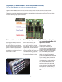
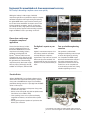
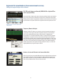
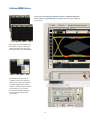
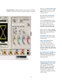
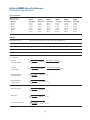
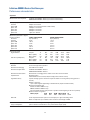
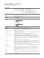
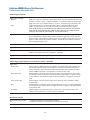
Agilent Infiniium 90000 Series Oscilloscopes
Data Sheet
Engineered for unmatched real-time measurement accuracy
Why choose Agilent oscilloscopes for your toughest high-speed measurement
challenges?
As an engineer you’re no stranger to tough challenges that
help you exceed your customer’s needs and expectations.
Deploying your next design successfully is even more
difficult with today’s high speed technologies. Data signal
eye openings become smaller and measurement error from
your oscilloscope becomes less tolerable. Agilent is
committed to providing the best measurement solutions
for these critical challenges.
The Agilent Infiniium 90000 Series oscilloscopes are
engineered to give you unmatched real-time measurement
accuracy so you can:
1. Use your jitter budget in your design, not on your oscilloscope.
2. Pass today’s demanding compliance tests more quickly.
3. Debug your toughest designs with confidence.
90000A Series Infiniium oscilloscopes
Model
Real-time
bandwidth on 4 ch
Maximum sampling
rate on 4 ch
Standard memory Maximum
memory
Noise floor at
50 mV/div
91304A
13 GHz
40 GSa/s on 4 ch
20 Mpts on 4 ch
1 Gpts on 4 ch
1.73 mVrms
91204A
12 GHz
40 GSa/s on 4 ch
20 Mpts on 4 ch
1 Gpts on 4 ch
1.45 mVrms
90804A
8 GHz
40 GSa/s on 4 ch
20 Mpts on 4 ch
1 Gpts on 4 ch
1.15 mVrms
90604A
6 GHz
20 GSa/s on 4 ch*
20 Mpts on 4 ch
1 Gpts on 4 ch
0.98 mVrms
90404A
4 GHz
20 GSa/s on 4 ch*
20 Mpts on 4 ch
1 Gpts on 4 ch
0.79 mVrms
90254A
2.5 GHz
20 GSa/s on 4 ch*
20 Mpts on 4 ch
1 Gpts on 4 ch
0.64 mVrms
*DSA model numbers come standard with 50 Mpts of memory on 4 ch.
How much time span can I capture?
Sampling Rate 20 Mpts of
memory
50 Mpts of
memory
100 Mpts of
memory
200 Mpts of
memory
500 Mpts of
memory
1 Gpts of
memory
40 GSa/s
500 μs
1.25 ms
2.5 ms
5.0 ms
12.5 ms
25.0 ms
20 GSa/s
1 ms
2.5 ms
5.0 ms
10.0 ms
25.0 ms
50.0 ms
Note: time span capture = memory depth x 1/ sampling rate
2
Engineered for unmatched real-time measurement accuracy.
Use your jitter budget in your design, not on your oscilloscope.
Agilent’s Infiniium 90000 Series oscilloscopes offer the industry’s lowest noise floor and most accurate real-time
jitter measurements available on scopes of this bandwidth class. Complete with full-bandwidth probing solutions and
hardwareaccelerated de-embedding and equalization techniques, Agilent oscilloscopes are the best oscilloscope solution
for today’s demanding high-speed measurements.
The industry’s lowest noise floor
Leveraging the company expertise in
RF design, Agilent has invested in key
technology blocks like our proprietary
Faraday caged front end to significantly
reduce our inherent scope noise floor.
The result: the lowest noise floor
available on any real-time oscilloscope
from 2.5 GHz to 12 GHz.
The industry’s deepest memory We add full bandwidth probing
and accurate de-embedding and
With 1 Gbyte of memory, lowequalization software
frequency jitter components can be
more quickly resolved in a single
measurement. Statistical accuracy is
improved with more data collection.
Agilent’s integrated deep memory
remains responsive and allows more
comprehensive testing, supporting
pattern lengths up to PRBS23 for
accurate transmitter and receiver
results.
3
The performance of Agilent’s
oscilloscopes is matched by the
superiority of our probing, de-embedding
and equalization offerings. Maintain full
bandwidth performance to the probe tip
with our InfiniiMax probing solutions.
Render waveforms anywhere in the
digital serial link with our hardware
accelerated N5465A InfiniiSim Waveform
Transformation Toolset. Configurable
system modeling allows you to remove
the deleterious effects of unwanted
channel elements, simulate waveforms
with channel models inserted, view
waveforms in physically unprobeable
locations, and compensate for loading of
probes and fixtures. The N5461A Serial
Data Equalization software allows you
to model equalization techniques in real
time.
Engineered for unmatched real-time measurement accuracy.
Pass today’s demanding compliance tests more quickly.
Offering the industry’s widest range of available
compliance applications to provide fast setup for complete,
automated compliance and margin testing and reporting,
the Agilent 90000 Series scopes have become the go-to
tool for test houses worldwide. Our experts serve on the
industry standards committees, and our oscilloscopes
are certified on today’s high speed serial data standards.
Plus our 1G memory supports real-time testing to pattern
lengths of PRBS23 to stress your design to the max.
Choose from a wide range
of complete compliance
applications
Choose from the industry’s widest
range of complete applications for
the Infiniium 90000 Series to ensure
compliance to the leading industry
standards, including SATA, PCI
Express®, Ethernet, USB, and more.
Comprehensive set-up wizards and full
automation of the required testing take
the guesswork out of demonstrating
compliance quickly. Get further insight
with our protocol and analysis decode
available on PCI Express, SATA and USB.
Put Agilent’s experts on your
team
Free up valuable engineering
resources
Agilent’s measurement experts sit on
the industry standards committees
and help define the compliance
requirements. They make sure our tools
deliver exactly to the standards. You
get the benefit of years of training and
experience on every measurement you
make.
Set-up wizards combined with
intelligent test filtering make it simple
to ensure the right tests are being
run. Comprehensive HTML reports
with visual documentation and pass/
fail results guarantee that critical
information is retained on each test.
Technicians can run complete and
accurate testing on their own, freeing
valuable engineering resources.
PrecisionProbe
Agilent’s N2809A-1NL PrecisionProbe software quickly
characterizes and compensates the frequency response
of any path to the 90000 Series input. PrecisionProbe’s
patented technology uses the < 15ps edge from the 90000
Series oscilloscope to:
• Measure input impedance and response of any probe and the loss of any cable
• Quickly correct from probe and cable loss(without extra instruments such as VNA or TDR)
• Correct probing issues such as phase nonlinearity, magnitude non-flatness, and see the effect of probe loading
• Quickly gain insight into impedance/capacitance that defines your connection
PrecisionProbe uses Agilent’s proprietar 200 GHz indium phosphide
process to create a fast edge for characterization with PrecisionProbe.
4
Engineered for unmatched real-time measurement accuracy.
Debug your toughest designs with confidence.
The 90000 series boasts an ever-expanding set of measurement applications
for serial debugging and protocol viewing, jitter testing, advanced triggering,
measurement customization, and rapid automation. Put the power of the scope to
work for your unique debug and analysis challenges.
Streamline your debug and analysis tasks with the industry’s widest
range of application software
Whether you need to trigger and decode serial buses, iron out the kinks in your
memory designs, or see FFT based spectrum analysis of your signal, the Infiniium
90000 Series has application software to help. Our serial protocol views are unique
to oscilloscopes, and our DDR debug tools support multiple generations of the
standard. Quickly access additional features from the scope’s standard menus.
Customize your scope for even more efficiency
The N5414B-1NL InfiniiScan Event Identification software makes unique capabilities
like Zone Qualify and Generic Serial triggering possible. Rapidly automate any
scope measurement using the N5467B-1NL User Defined Application and have it
appear seamlessly in your scope’s menu. Customize your Infiniium further by taking
full advantage of MyInfiniium (standard on all 90000A Series oscilloscopes). Use
MyInfiniium to deliver automated measurements, execute customized scripts, save
screenshots, or load your favorite setup.
Add measurement capability with MATLAB compatibility
If we haven’t provided exactly what you need, take customization to a new level
with MATLAB (Option 062) - a data analysis software environment and scripting
language with over 1,000,000 users today. Use MATLAB to design and apply your
own filters to oscilloscope signals, graphically visualize oscilloscope signals in
2-D and 3-D plots, automate measurements, and build test applications. Add the
N5430A-1NL User Defined Function software to your scope to seamlessly integrate
your custom functionality into the Infiniium 90000 menus so results are displayed
on the scope screen. Agilent is the only T&M manufacturer today that sells and
supports MATLAB as its own product as part of a complete T&M solution.
5
Engineered for unmatched real-time measurement accuracy.
Debug your toughest designs with confidence.
I2C/SPI serial trigger and decode (N5391A-1NL or Option 007 on
new scope purchases)
Given even further insights with protocol decode capability. Quickly move between
physical and protocol layer information using the time-correlated tracking marker.
Display protocol content using waveform symbols and the industry’s first multi-tab
protocol viewer. The packets tab shows a high level view of the packet over time.
Trigger and view on-screen serial decode
of I2C packets
Frequency Domain Analysis
Infiniium’s built-in FFT allows users to quickly and easily analyze the frequency
components of their signals. Both FFT magnitude and phase can be displayed
and can be combined with other built-in math functions or Matlab based
measurements. A resolution bandwidth of 6 kHz is supported with the standard
10 Megabytes of acquisition memory at the maximum sample rate of 40 GSa/s.
With optional acquisition memory installed resolution bandwidths of 2 kHz can be
obtained. Standard windowing of Hanning, Flattop and Rectangular are supported
along with cursor based power measurements. When more powerful frequency
domain measurements are required including modulation analysis, consider the
Agilent 89601A Vector Signal Analyzer software.
Hardware Accelerated Differential and Common Mode Math
Select the channel menu and enable differential mode to enable hardware accelerated
math capability. Enjoy full channel functionality including InfiniiScan triggering and
jitter analysis. Save time, by using the hardware acceleration for even faster update
rates with your differential and common mode math needs.
6
Debug your toughest designs with confidence
EZJIT analysis software (E2681A-1NL or option 002 on new scope purchases)
Quickly characterize and evaluate most commonly needed jitter measurements,
including cycle-cycle, N-cycle, period, time-interval, error, setup and hold time,
histograms, measurement trending and jitter spectrum.
Includes advanced clock recovery options such as constant frequency and PLL.
Make measurements on repetitive or arbitrary data.
This application is supported on all models and is standard on DSA models.
Conduct jitter analysis.
For more information: www.agilent.com/find/EZJIT
EZJIT Plus analysis software (N5400A-1NL or Option 004 on new scope purchases.
To upgrade from EZJIT to EZJIT Plus, order N5401A.)
EZJIT Plus adds additional compliance views and an expanded measurement setup wizard
to simplify and automate RJ/DJ separation for testing against industry
standards.
This application is supported on all models and is standard on DSA models.
For more information: www.agilent.com/find/EZJITPlus
Analyze jitter plus RJ/DJ separation.
EZJIT Complete analysis software (N8813A-1NL or Option 070 on new scope purchases)
EZJIT Complete includes all of the advanced jitter analysis capabilities of EZJIT and
EZJIT Plus, and adds advanced analysis of the vertical noise affecting the ones and
zeros of your real-time eye. Decomposition of vertical noise provides key insight into
degradation of your eye height. In providing advanced decomposition of both
horizontal jitter and vertical noise components of your signals, EZJIT Complete
represents the most comprehensive analysis software available.
EZJIT Complete.
This application is supported on all models and is a standard on DSA models.
For more information: www.agilent.com/find/EZJITComplete
7
Debug your toughest designs with confidence
InfiniiScan event identification (N5414B-1NL or Option 009 on new scope
purchases)
Rapidly trigger on complex events and identify signal integrity issues. This innovative
software quickly scans through thousands of acquired waveform cycles and isolates
anomalous signal behavior.
This application is supported on all models.
For more information: www.agilent.com/find/infiniiScan
Identify signal integrity issues with InfiniiScan
Zone – Qualify triggering.
PrecisionProbe software (N2809A-1NL or Option 001 on new scope purchases)
Make more accurate measurements independent of what probes or cables used.
Agilent’s N2809A PrecisionProbe software characterizes and corrects for the loss
in your specific cable or probe. PrecisionProbe removes the uncertainty about the
input connected to your oscilloscope by allowing you to see its characteristics in
less than five minute. PrecisionProbe gives you design and debug confidence by
allowing you to quickly de-embed probe and cable loss to make more accurate
measurements.
Quickly characterize and correct for any input
to your oscilloscope.
For more information: www.agilent.com/find/PrecisionProbe
High-speed serial data analysis software (E2688A-1NL or Option 003 on new scope
purchases)
Quickly validate signal integrity for high-speed serial interfaces with embedded clocks.
Recover embedded clocks synchronized with the analog waveform view. Build and
validate eye diagrams.
The SDA package also includes software-based bit-level triggering and decode for
8B/10B. This application is supported on all models and comes standard on DSA
models.
Recover embedded clocks with serial data
analysis (SDA).
For more information: www.agilent.com/find/SDA
8
Debug your toughest designs with confidence
Infiniium Remote Programming interface (Now standard on all Infiniium scopes)
Operate your Infiniium compliance and validation applications remotely using .NET
languages.
This application is supported on all models.
For more information: www.agilent.com/find/RPI
Control your applications remotely.
Serial Data Equalization (N5461A-1NL or Option 012 on new scope purchases)
Measure at the pin and use equalization to see a virtual eye on the other side of an
equalizer. Model equalization techniques such as DFE, FFE, and CTLE.
This application is supported on all models.
For more information: www.agilent.com/find/SDE
Reduce receiver errors by opening tightly shut eyes.
InfiniiSim Waveform Transformation and De-embedding Toolset (Basic: N5465A-3NL
or option 13 on new scope purchases. Advanced: N5465A-1NL or Option 14 on new
scope purchases.)
Model channel effects including reflection.
The N5465A InfiniiSim waveform transformation toolset for Infiniium Series
oscilloscopes provides the most flexible and accurate means to render waveforms
anywhere in the digital serial link. The configurable system modeling allows you to
remove the deleterious effects of unwanted channel elements, simulate waveforms
with channels models inserted, view waveforms in physically un-probable locations,
compensate for loading of probes and other circuit elements, and do so simply and
quickly on the real-time oscilloscope.
This application is supported on all models.
For more information: www.agilent.com/find/InfiniiSim
9
Debug your toughest designs with confidence
MATLAB® data analysis software (Option 061 or O62 on new scope purchases)
Control your applications remotely.
MATLAB is a data analysis software environment and scripting language used by over
1,000,000 users in aerospace/defense, automotive, communications, electronics, and
other applications. MATLAB is now available directly from Agilent as in instrument
option with the purchase of your Agilent 90000 Series oscilloscope. Install MATLAB
on your oscilloscope or remote PC to make customized measurements, design and
apply your own filters to oscilloscope signals, graphically visualize signals in 2-D or
3-D plots, automate measurements, or build test applications. Purchase MATLAB with
your Agilent 90000 Series oscilloscope to ensure version compatibility and so that your
MATLAB software license is always available when you need it.
For more information: www.agilent.com/find/matlab_oscilloscopes
User-definable application (N5467B-1NL or Option 040 on new scope purchases)
Rapidly develop your own automated measurements and tests. This application
provides the framework you need to quickly program and automate any single or set of
measurements the oscilloscope can make. The application also provides full control of
other Agilent instruments and HTML reporting capabilities. For more information: www.agilent.com/find/UDA
Quickly automate oscilloscope measurements.
User-defined function (N5430A-1NL or Option 010 on new scope purchases)
If we haven’t provided exactly what you need, use the N5430A User Defined Function
software to create it yourself. Develop your own math functions or filters using
MATLAB. Your custom functionality is seamlessly integrated into the Infiniium 90000
menus and results are displayed on the scope screen. This requires MATLAB
(available as Option 062) to be installed directly on the oscilloscope. Agilent is the only
T&M manufacturer today that sells and supports MATLAB as its own product.
Signal equalization using user-defined function.
This application is supported on all models and requires MATLAB software (not
included with UDF).
For more information: www.agilent.com/find/UDF
Vector signal analysis software (89601A)
Expand the measurement capability of your scope with the 89601A vector signal analysis software. This advanced DSP-based software takes the digitized signal data from
the scope and displays FFT-based spectrum analysis and wide-bandwidth digital modulation analysis for wireless communication signals such as WCDMA and cdma2000
and wireless networking signals such as 802.11 WiFi and 802.16 WiMax.
Take advantage of the super-wide bandwidth of your scope to capture and evaluate
radar signals.
Use vector signal analysis software to see
FFT-based spectrum analysis.
For more information: www.agilent.com/find/VSA
10
Debug your toughest designs with confidence
I2C/SPI serial trigger and decode (N5391A-1NL or Option 007 on new scope
purchases)
This application displays real-time time-aligned decode of I2C and SPI packets. View
decode in waveform area or in protocol lister.
This application works on all models.
For more information: www.agilent.com/find/90000_I2C-SPI
Trigger and view on-screen serial decode
of I2C packets.
JTAG (IEEE 1149.1) triggering and decode (N8817A-1NL or Option 042 on new scope
purchases)
This application displays real-time time-aligned decode of JTAG (IEEE 1149.1) TDI
and TDO signals. The application eliminates the difficult task of manually determining JTAG TAP controller states, instruction and data register decode, and flags error
conditions. The application includes scan chain description features including the
ability to import .bsdl files for each device and displays device names and opcodes in
the protocol listing.
Trigger on and decode JTAG packets.
This application works on all models and can use any combination of scope or logic
acquisition channels.
For more information: www.agilent.com/find/90000_JTAG
RS-232/UART serial decode and trigger (N5462A-1NL or Option 015 on new scope
purchases)
This application eliminates the need to manually decode bus traffic. Using data captured
on the scope channels, the application lets you easily view the information sent over an
RS-232.
Display real-time time-aligned decode of transmit and receive lines.
This application works on all models.
Trigger on and decode RS-232/UART
transmission.
For more information: www.agilent.com/find/90000_RS-232
N8805A-1NL USB 3.0 Protocol Triggering and Decode
Trigger on and view USB 3.0 with the industry’s first oscilloscope-based protocol
analyzer with time-correlated views of physical layer and transaction layer errors.
The multi-tab protocol viewer includes correlation between the waveforms and the
selected packet, enabling you to quickly move between the physical and protocol layer
using the time-correlated tracking marker.
For more information: www.agilent.com/find/usb3decode
Isolate signal integrity problems from logic-level coding
errors on bidirectional serial data streams.
11
Pass today’s demanding compliance tests more quickly
USB serial trigger and protocol viewer (N5464A-1NL or Option 016 on new scope
purchases)
Trigger on and quickly view USB 2.0 packets, payload, header and detail information.
Powerful time-correlated views of waveform and symbol, to the bit level, make it easy
to isolate communication faults.
This application is supported on all models.
For more information: www.agilent.com/find/90000_USB_protocol_viewer
Trigger on and decode USB packets.
PCI Express® serial trigger and protocol viewer (N5463A-1NL or Option 017 on new
scope purchases)
This application provides protocol-level triggering and viewing of a PCIe® lane. Quickly
view packets, payload, header, and detail information. Powerful time-correlated views
of waveform, symbol, character, link and transaction layer packet data down to the bit
level make it easy to isolate communication faults to logic or analog sources.
This application is supported on all 4 GHz and greater models.
Trigger on and decode PCIe serial packets.
For more information: www.agilent.com/find/90000_PCI_protocol_viewer
SATA triggering and decode (N8801A-1NL or Option 018 on new scope purchases)
Trigger on and view both protocol layer information and physical layer signal
characteristics for SATA 1.5 Gb/s, 3.0 Gb/s, and 6.0 Gb/s. Numerical decode values
are automatically displayed and synchronizes below the capture signal or seen in
protocol viewer.
This application works on all models.
For more information: www.agilent.com/find/N8801A
Trigger on and decode SAS/SATA serial packets.
12
Pass today’s demanding compliance tests more quickly
MIPI D-phy trigger and decode (N8802A-1NL or Option 019 on new scope
purchases)
This application eliminates the need to manually decode bus traffic. Using data
captured on the scope, the application lets you easily view the information sent over
MIPI serial buses.
The application also enables software based protocol triggering.
This application is supported on all models >=4 GHz bandwidth.
For more information: www.agilent.com/find/N8802A
Trigger on and decode MIPI packets.
Ethernet compliance testing (N5392B-3NL or Option 021 on new scope purchases)
Perform a wide range of electrical tests for 10-, 100-, and 1000-Base-T systems. An
N5395B or N5395C test fixture and N5396A jitter test cable speed compliance testing.
This application is supported on all models.
For more information: www.agilent.com/find/N5392B
Validate Ethernet compliance.
PCI EXPRESS® Electrical Performance Validation and Compliance Software
(N5393D-3NL or Option 022 on new scope purchases)
Provides fast and easy way to verify and debug your PCI EXPRESS designs. Allows
you to automatically execute PCI EXPRESS electrical checklist tests, and displays
the results in a flexible report format. Ensures that your Gen2 measurements will
have absolute consistency with measurements made using the PCI-SIG’s standalone
Sigtest software.
PCI Express also comes with a receiver calibration option by ordering N5393D-4NL
and switch matrix support by ordering N393D-7NL. This application is supported on
all models >=8 GHz bandwidth.
Quickly verify and debug your PCI EXPRESS®
designs.
For more information: www.agilent.com/find/N5393D
HDMI™ Electrical Performance Validation and Compliance Software (PCI Express
also comes with a receiver calibration option by ordering N5393D-4NL and switch
matrix support by ordering N5393D-7NL)
Quickly verify and debug your High Definition Multi-media Interface (HDMI) designs.
The N1080A fixture provides access to the compliance points for the electrical
measurements required for the transmitter compliance testing.
Verify and debug your HDMI designs.
Switch matrix support is available by ordering N5399C-7NL (Option 702 on new
scope purchases). This application is support on all models >=8 GHz bandwidth.
For more information: www.agilent.com/find/N5399C
13
Pass today’s demanding compliance tests more quickly
Energy Efficient Ethernet Application (N5392B-1NL or Option 060 on new scope purchases)
Characterize and evaluate the signal
integrity of your Energy Efficient
Ethernet devices.
Industry leading compliance application that measures 10/100/1000BTe Energy Efficient
Ethernet IEEE 802.3az-2010 specification. Exclusive EEE fixture allows you to measure
all test modes at all speeds. Detailed reporting with clear measurements and pass/fail
results.
This application is supported on all models.
For more information: www.agilent.com/find/EEE
SATA 6G Compliance Test Software (N5411B-1NL or Option 038 on new scope purchases)
Rapidly validate and debug your SATA 1.5Gb/s (Gen 1), 3.0 Gb/s (Gen2) and 6.0 Gb/s
(Gen3) silicon, host bus adapter, port multiplier, high-density disk drive, solid-state
disk drive or optical disk drive. Provides automated compliance test support for the i
(internal), m(eSATA) and x(SAS attachment) interfaces points, and displays the results
in a flexible report format.
This application is supported on all models >= 12 GHz bandwidth.
For more information: www.agilent.com/find/N5411B
Simplify the validation of SATA designs.
DisplayPort 1.2 Compliance Test Software (U7232C-1NL or Option 045 on new scope
purchases)
Full suite of DisplayPort source tests.
Sets the benchmark for ease-of-use, and offers complete testing without compromise.
The software guides the user sequentially through the tasks ensuring minimal setup error,
executes the tests specified by the standard and conveys the test information through a
convenient software generated report. The three modes of physical layer test allow for
automated measurements based on the customizable configuration of compliance and
characterization testing. To make the test signal connection, the Agilent W2641B DisplayPort test point access adaptor completes the DisplayPort source solution.
DisplayPort 1.2 also comes with switch matrix support to make multi-lane testing
significantly easier by ordering U7232C-7NL (Option 701 on new scope purchases). The
application is supported on all models >= 8 GHz.
For more information: www.agilent.com/find/U7232C
14
Pass today’s demanding compliance tests more quickly
USB 2.0 Compliance Test Software (N5416A-1NL or Option 029 on new scope
purchases)
Quickly determine USB compliance with this USB-IF recognized solution. A setup
wizard guides you through test selection and configuration.
This application is supported on all models.
For more information: www.agilent.com/find/N5416A
Check for USB compliance.
XAUI Electrical Validation with 10GBASE-CX4, CPRI, OBSAI, and Serial RapidIO
Support (N5431A-1NL or Option 030 on new scope purchases)
Improve your efficiency by confirming that your devices conform to the XAUI specifications as defined by the IEEE 802.3-2005 10-gigabit Ethernet specification. Provides
support for the XAUI-derived 10GBASE-CX4 specification.
The application is supported on all models.
For more information: www.agilent.com/find/N5431A
Perform automated testing and margin analysis
for XAUI and XAUI-derived specifications.
MIPI D-PHY Compliance Test Software (U7238C-1NL or Option 035 on new scope
purchases)
Automatically execute D-PHY electrical checklist tests for CSI and DSI architectures.
Displays the results in a flexible report format.
MIPI D-PHY also supports the ability to test compliance with switches, making your testing faster, by ordering U7238C-7NL (Option 703 on new scope purchases). The application is supported on all models.
For more information: www.agilent.com/find/d-phy_compliance
Automatically execute D-PHY electrical checklist
tests for CSI and DSI architectures.
15
Pass today’s demanding compliance tests more quickly
10GBASE-T Ethernet Electrical Conformance Application for Infiniium Oscilloscopes
(U7236A-1NL or Option 036 on new scope purchases)
Takes care of the tedious task of instrument control and configures the oscilloscope,
spectrum analyzer, or vector network analyzer as needed by each 10GBASE-T test to
provide rapid, accurate, and repeatable test execution.
The application is supported on all models.
For more information: www.agilent.com/find/10gbase-t
Automatically execute 10GBASE-T Ethernet
physical-layer (PHY) electrical tests
USB 3.0/3.1 Compliance Test Software (U7243B-3NL or Option 041 on new scope
purchases
Provides industry leading automated test support for USB 3.0 products and displays the
test results in a comprehensive test report. For best measurement accuracy use the
Agilent U7243B USB 3.0 transmitter and receiver test fixtures. Agilent’s USB 3.0 test
solution is designed from the ground up with the needs of the test engineer in mind.
The application is supported on models >= 12 GHz
Validate and debug your USB 3.0 silicon,
host, hub or device
For more information: www.agilent.com/find/USB3
DDR1 and LPDDR/DDR2, LPDDR2/DDR3, DDR4 and GDDR5 compliance testing
(Options 031/032/033/058 on new scope purchases)
Quickly and easily evaluate and characterize your memory designs. Automated testingbased on JEDEC specifications saves time. The application also includes additional
debug and compliance capabilities.
This application is supported on all models. However, the DDR technology you are
using may dictate the minimal bandwidth required for your scope.
Test DDR memory.
For more information: www.agilent.com/find/DDR
SD UHS-I and SD UHS-II Card Compliance Testing (U7246A-1NL/N6461A-1NL)
The SD card compliance test software gives you a fast, easy way to test, debug and
characterize your SD designs up to 1.5 Gb/s in accordance with the SD Specification.
The U7246A with 9000A and 90000A Series oscilloscopes is a certified test tool for SD
Card Phy electric tests with the SD Association. Reference is available in SDA official
document: SD Test Tool Information Ver1.0 Sep. 13, 2010.
Comprehensive analysis that automates
the complex measurements even when
you are not there.
For more information: www.agilent.com/find/U7246A
www.agilent.com/find/N6461A
16
Agilent Infiniium portfolio
Agilent’s Infiniium oscilloscope lineup includes bandwidths from 500 MHz to 63 GHz. Use the following selection guide to
determine which best matches your specific needs. Infiniium real-time oscilloscopes feature the following:
• World’s highest bandwidth on 4 channels in a single frame
• Industry’s lowest noise floor
• Full PrecisionProbe compatibility
Available bandwidths
S-Series
90000A Series
Up to 4 GHz
500 MHz, 1 GHz,
2.5 GHz, 4 GHz
2.5 GHz, 4 GHz
6 to 16 GHz
6 GHz (2 ch), 8 GHz
(2 ch)
6 GHz, 8 GHz 12
GHz, 13 GHz
20 to 63 GHz
90000 X-Series
Z-Series
13 GHz, 16 GHz
20 GHz, 25 GHz,
33 GHz
20 GHz, 25 GHz,
33 GHz, 50 GHz,
63 GHz
Max upgradable bandwidth
8 GHz
13 GHz
33 GHz
63 GHz
Sample rate (2-channel/4-channel)
10/20 GSa/s
40/40 GSa/s
80/40 GSa/s
160/80 GSa/s
Channel inputs and connector types
50Ω and 1 MΩ,
BNCs
50 Ω, BNCs
50 Ω, 2.92 and
3.5 mm SMAs
50 Ω, 1.85 mm,
2.4, mm, 2.92 and
3.5 mm, SMAs
Memory depth (standard/max)
50 M/1 Gpts
20 M/2 Gpts
20 M/2Gpts
50 M/2 Gpts
MSO models
Yes
No
No
No
Supported InfiniiMax probe families
InfiniiMax 2
InfiniiMax 2
InfiniiMax 3
InfiniiMax 2 with
adapter
InfiniiMax 3
InfiniiMax 2 with
adapter
17
Infiniium 90000A Series
Starting with an 18-GHz, BNC-compatible connector, an ultra‑low noise floor
front end design using Faraday cage technology ensures high signal integrity in
its signal path.
Click on the icon at the bottom left of
the Infiniium screen to minimize the
status and scales tab for full screen
viewing. Maximize your viewing needs.
Ever wanted to change the scale
or offset of a function or waveform
memory? If you have, you know that
it requires multiple menus and key
strokes. In Infiniium software version
2.01 and later, you can now map
functions and waveform memories
to the front panel controls of the
oscilloscope!
18
AutoProbe interface completely configures your scope for use with the
InfiniiMax probing system and previous-generation Agilent active probes.
Simply press the horizontal delay knob
to set the delay value to zero. A zoom
button provides quick access to two
screen zoom mode.
Dedicated single acquisition button
provide better control to capture an
unique event.
Customizable Multipurpose key gives
you any five automated measurements
with a push of a button. You can
also configure this key to execute a
script, print/save screen shots, save
waveforms, or load a favorite setup.
Measure section including a toggling
marker button and a dedicated marker
knob provides quick access to your
marker control.
Quick access to fine/vernier control
by pressing the horizontal and vertical
sensitivity knobs.
Increase your productivity with
a familiar Infiniium graphical
user interface, like your favorite
drag‑and‑drop measurement icons.
Infiniium’s analog-like front panel has
a full set of controls color coded to the
waveforms and measurements, making
your tasks simple.
Optional USB external DVD-RW drive
allows you to install your favorite
third‑party software conveniently and
can be used to back up your critical
measurement data.
Install third-party software packages
on Windows XP Pro operating system
such as Excel, LabVIEW, Agilent
VEE, MATLAB®, anti-virus software,
and more, to perform customized
processing and automation of your
oscilloscope or to make the scope
compliant to the network environment
of your company.
19
InfiniiMax II: The World’s best high-speed probing system
just keeps getting better
InfiniiMax offers you the highest performance available for mea‑
suring differential and single‑ended signals,
with flexible connectivity solutions for
today’s high-density ICs and circuit boards.
InfiniiMax probes have fully
characterized performance for all
of their various probe heads. This includes:
• Swept frequency response plot
• Common mode rejection versus
frequency plot
• Impedance versus frequency plot
• Time-domain probe loading plot
• Time-domain probe tracking plot
One-year standard warranty on
active probes and a variety of Agilent
support options to choose from.
Controlled impedance
transmission lines in every probe
head deliver full performance versus the
performance limitations introduced by
traditional wire accessories.
Probe interface software allows
you to save the calibration information for
up to 10 different probe heads per channel
and will automatically retrieve calibration
data for a probe amplifier when attached to
the scope.
High-input impedance active
probes minimize loading, support
differential measurements and DC offset,
and can compensate for cable loss.
Probe calibration software
delivers the most accurate probe
measurements and linear phase response
and allows various probe combinations to
be deskewed to the same reference time.
A flat frequency response over
E2677A 12‑GHz solder-in
differential probe head can be
attached to very‑small‑geometry circuits
for measuring both single-ended and
differential signals. External mini-coaxial
resistors facilitate wider span but have
increased high-frequency response
variation relative to N5381A.
E2679A 6‑GHz extremely
small single-ended, solder‑in
probe heads for probing even the
hardest‑to‑reach single-ended signals.
N5381A 13‑GHz high‑
bandwidth solder‑in differential
probe head provides maximum
bandwidth and minimizes capacitive loading
to ≤ 210 fF. Variable spacing from
0.2 to 3.3 mm (8 to 130 mills).
N5425A 13‑GHz high‑
bandwidth solder‑in differential
ZIF probe head and N5426A
ZIF tip provides maximum bandwidth
N5426A
with the industry’s first lead-free solderin probe solution in an economical
replaceable tip form factor.
N5451A 9‑GHz/5‑GHz long-wire
ZIF tip provides a high‑bandwidth
economical replaceable solder-in tip with
extra reach (9 GHz with 7 mm and 5 GHz
with 11 mm wire).
E2695A 8-GHz differential SMA
the entire probe bandwidth eliminates the
probe head allows you to connect
distortion and frequency‑dependent loading two SMA cables to make a differential
effects that are present in probes that have measurement on a single scope channel.
an in-band resonance.
20
N5451A
Six different InfiniiMax probe amplifiers from 1.5 GHz to 13 GHz are available for matching
your probing solution to your performance and budget requirements. The 1168/69A
InfiniiMax II amplifiers offer the highest bandwidth and the lowest noise floors. The
1134/32/31/30A offer a more cost efficient solution and wider dynamic range.
N5382A 13‑GHz high‑bandwidth
differential browser provides
maximum bandwidth for hand-held or probe
holder use. Variable spacing from 0.2 to 3.3
mm (8 to 130 mills).
N2884A Differential Fine-wire
Probing Tip InfiniiMax differential
fine-wire probing tip is a high fidelity, high
bandwidth solution for probing an active IC.
E2675A 6‑GHz differential
browser is the best choice for general-
purpose trouble shooting of differential or
single-ended signals with z-axis compliance
and variable spacing from 0.25 - 5.80 mm
(10 - 230 mills).
E2676A 6‑GHz single-ended
browser is the best choice for generalpurpose probing of single-ended signals
when the small size of the probe head is
the primary consideration.
E2678A 12‑GHz differential
socket probe head can be used to
N2887A InfiniiMax Soft touch
Pro Probe Adapter adapts from
the Agilent Pro Series (36 ch) Soft touch
connectorless logic analyzer foot print to
the Agilent InfiniiMax I & II series probe
amplifier input connectors
measure either differential or single‑ended
signals via a plug-on socket connection.
N2880A In-line Attenuator Kit
N5380B 13‑GHz high‑bandwidth
differential SMA probe head provides
allows you to increase the dynamic range
and the offset range of the InfiniiMax probe
without affecting the bandwidth.
maximum bandwidth for SMA‑fixtured
differential pairs.
N5450B InfiniiMax extreme
temperature extension cable
provides extra reach into environmental
chambers.
N2881A DC Blocking
Capacitors can be used to in series
with the N2880A InfiniiMax in-line
attenuators to block out unwanted DC
components of the input signal up to 30V.
21
N2888A InfiniiMax Soft touch
half-channel Probe Adapter
adapts from the Agilent half-channel
(18 ch) Soft touch connectorless logic
analyzer foot print to the Agilent InfiniiMax
I & II series probe amplifier input connectors
Infiniium 90000A Series Oscilloscopes
Performance characteristics
Vertical
Input channels
Four
Analog bandwidth
(–3 dB)*, 10
90254A 2.5 GHz DSP enhanced bandwidth3
91304A: 13-GHz real-time, user-selectable DSP enhanced bandwidth
Rise time/fall time11
10 - 90%
20 - 80%
90254A 140 ps 105 ps Input impedance12
50 Ω, ± 3%
Sensitivity1
1 mV/div to 1 V/div
Input coupling
DC
Vertical resolution2
8 bits, ≥ 12 bits with averaging
Channel to channel isolation
(any two channels with
equal V/div settings)
DC to 3 GHz: 90804A/91204A/91304A: 60 dB (≥ 1000:1)
90254A/90404A/90604A: 50 dB (≥ 316:1)
3 GHz to 8 GHz: 40 dB (≥ 100:1)
8 GHz to BW: 35 dB (≥ 56:1)
DC gain accuracy*, 1
± 2% of full scale at full resolution channel scale (± 2.5% for 5mV/div)
Maximum input voltage*
±5V
Offset range
Vertical sensitivity
0 mV/div to ≥ 40 mV/div > 40 mV/div to ≥ 75 mV/div > 75 mV/div to ≥ 130 mV/div > 130 mV/div to ≥ 240 mV/div > 240 mV/div Offset accuracy*, 1
≤ 3.5 V: ± (2% of channel offset + 1% of full scale) + 1 mV
> 3.5 V: ± (2% of channel offset + 1% of full scale)
Dynamic range
± 4 div from center screen
DC voltage measurement
accuracy*, 1
Dual cursor: ± [(DC gain accuracy) + (resolution)]
Single cursor: ± [(DC gain accuracy) + (offset accuracy) + (resolution/2)]
RMS noise floor (scope only)
Volts/div
5 mV
10 mV
20 mV
50 mV
100 mV
200 mV
500 mV
1V
90254A 153 μV
183 μV
275 μV
645 μV
1.27 mV
2.47 mV
6.48 mV
12.5 mV
90404A 4 GHz 90604A 6 GHz 90404A 105 ps 79 ps 90604A 70 ps 53 ps 90404A 199 μV
232 μV
342 μV
799 μV
1.56 mV
3.03 mV
8.00 mV
15.6 mV
90804A 8 GHz 90804A 54 ps 38 ps
91204A 12 GHz 91204A 35 ps 25 ps 91304A
12 GHz
91304A
32 ps
23 ps
Available offset
± 0.4 V
± 0.9 V
± 1.6 V
± 3.0 V
± 4.0 V
90604A 259 μV
295 μV
424 μV
985 μV
1.92 mV
3.71 mV
9.91 mV
19.2 mV
90804A 322 μV
358 μV 498 μV 1.15 mV
2.22 mV
4.28 mV
11.5 mV
22.3 mV
91204A 435 μV
483 μV
650 μV
1.45 mV
2.80 mV
5.41 mV
14.7 mV
28.5 mV
91304A
467 μV
536 μV
758 μV
1.73 mV
3.37 mV
6.58 mV
17.4 mV
34.1 mV
* Denotes warranted specifications, all others are typical. Specifications are valid after a 30-minute warm-up period, and ±5 °C from annual calibration temperature.
1 Full scale is defined as 8 vertical divisions. Magnification is used below 5 mV/div. Below 5 mV/div, full-scale is defined as 40 mV. The major scale settings are 5 mV, 10 mV, 20
mV, 50 mV, 100 mV, 200 mV, 500 mV, 1 V.
2 Vertical resolution for 8 bits = 0.4% of full scale, for 12 bits = 0.024% of full scale.
3 13 GHz DSP enhanced bandwidth not applicable at 5 mV/div.
10 11.8 GHz analog bandwidth at 5 mV/div for DSO91304A and DSO91204A models.
11 Calculated from the bandwidth.
12 Input impedance is valid when V/div scaling is adjusted to show all waveform vertical values within the scope display.
22
Infiniium 90000A Series Oscilloscopes
Performance characteristics
Vertical (continued)
RMS noise floor
(scope with probe)
Volts/div
20 mV
50 mV
100 mV
200 mV
500 mV
1V
90254A with 1131A
3.2 mV
3.3 mV
3.4 mV
4.0 mV
7.1 mV
13 mV
90404A with 1132A
3.5 mV
3.6 mV
3.8 mV
4.6 mV
8.6 mV
16 mV
90604A with 1134A
4.0 mV
4.0 mV
4.3 mV
5.3 mV
10 mV
19 mV
90804A with 1168A
2.2 mV 2.3 mV
2.9 mV
4.7 mV
12 mV
23 mV
91204A with 1169A
2.5 mV
2.8 mV
3.5 mV
5.9 mV
15 mV
28 mV
Horizontal
Main timebase range
5 ps/div to 20 s/div real-time, 5 ps/div to 500 ns/div equivalent-time
Main timebase delay range
–200 s to 200 s real-time, –25 μs to 200 s equivalent-time
Zoom timebase range
1 ps/div to current main time scale setting
Channel deskew
± 25 μs range, 100 fs resolution
Time scale accuracy*
± (0.4 + 0.5 * YrsSinceCal) ppm pk
Delta-time measurement
accuracy6a, 6b, 7
Absolute,
averaging disabled
√(
)
Absolute,
>- 256 averages
√(
)
Standard deviation,
averaging disabled
√(
)
Standard deviation,
>- 256 averages
√(
)
Time interval error6c
√(
)
Period jitter
√(
)
N-cycle, cycle-cycle jitter
√(
)
TimeScaleAccy • Reading
5.0 • Noise 2
sec pk
+ 20x10–24 +
SlewRate
2
TimeScaleAccy • Reading
0.35 • Noise 2
sec pk
+ 0.1x10⁻²⁴ +
SlewRate
2
1.4 • Noise 2
+ 0.6x10⁻²⁴ sec rms
SlewRate
0.1 • Noise 2
+ 0.01x10⁻²⁴ sec rms
SlewRate
Jitter measurement floor6a, 6b
1.0 • Noise 2
+ 0.3x10⁻²⁴ sec rms
SlewRate
1.4 • Noise 2
+ 0.6x10⁻²⁴ sec rms
SlewRate
2.4 • Noise 2
+ 1.7x10⁻²⁴ sec rms
SlewRate
23
91304A
with 1169A
2.7 mV
3.1 mV
4.2 mV
7.5 mV
19 mV
37 mV
Infiniium 90000A Series Oscilloscopes
Performance characteristics
Acquisition
Maximum real-time sample rate
91304A/91204A/90804A: 40 GSa/s (4 channels simultaneously)
90604A/90404A/90254A: 20 GSa/s (4 channels simultaneously)
Memory depth per channel
Standard
Option 50M
Option 100
Option 200
Option 500
Option 01G
20 Mpts on 4 channels
50 Mpts on 4 channels (standard on DSA models)
100 Mpts on 4 channels
200 Mpts on 4 channels
500 Mpts on 4 channels
1 Gpts on 4 channels
Maximum acquired time at highest
real-time resolution
Resolution
Standard
Option 50M
Option 100
Option 200
Option 500
Option 01G
91304A/91204A/90804A90604A/90404A/90254A
25 ps (40 GSa/s)
50 ps (20 GSa/s)
0.5 ms
1.0 ms
1.25 ms
2.5 ms
2.5 ms
5.0 ms
5.0 ms
10.0 ms
12.5 ms
25.0 ms
25.0 ms
50.0 ms
Data transfer speed
Gigabit Ethernet
USB 2.0 hi-speed (device)
Sampling modes
Real-time
Real-time with averaging
Real-time with peak detect
Real-time with hi resolution
Equivalent-time
Segmented memory
Roll mode
Filters
Sin(x)/x Interpolation
Samples:
1 k
64 k
1 M
16 M
32 M
128 M
MSa/s (Word): 0.1 1.88 9.25 12.0012.8012.80
MSa/s (Byte): 0.11 1.88 12.6019.7020.3022.00
Samples:
1 k
64 k
1 M
16 M
32 M
128 M
MSa/s (Word):0.111.888.348.559.0711.38
MSa/s (Byte): 0.11 1.88 11.6014.4014.9018.10
Successive single-shot acquisitions
Selectable from 2 to 65534
91304A/91204A/90804A: 40 GSa/s
90604A/90404A/90254A: 20 GSa/s
Real-time boxcar averaging reduces random noise and increases resolution
Resolution: 100 fs
Full bandwidth on all 4 channels, 262,144 sample points maximum memory
Captures bursting signals at maximum sample rate without consuming memory during periods of
inactivity
Number of segments:
Up to 131,072 segments (depending on installed memory depth and model number)
Minimum intersegment time:
91304A / 91204A / 90804A: 2.7 μs
90604A / 90404A / 90254A: 2.5 μs
(the time between the end of the previous acquisition and the beginning of the next acquisition)
Maximum number of segments:
Memory depth: 20 M 50 M 100 M 200 M 500 M 1 G
4096 8192
16384 32768 65536 131072
Scrolls sequential waveform points across the display in a right-to-left rolling motion.
Works at sample rates up to 10 MSa/s with a maximum record length of 40MS.
On/off selectable FIR digital filter. Digital signal processing adds points between acquired data
points to enhance measurement accuracy and waveform display quality.
24
Infiniium 90000A Series Oscilloscopes
Performance characteristics
Hardware trigger
Sensitivity1
91304A/91204A/90804A: Internal low1: 2.0 div p-p 0 to 5 GHz
Internal high1: 0.3 div p-p 0 to 4 GHz, 1.0 div p-p 4 to 7.5 GHz
11
90604A/90404A/90254A : Internal low1: 2.0 div p-p 0 to 5 GHz
Internal high1: 0.3 div p-p 0 to 3 GHz, 1.0 div p-p 3 to 5 GHz
Auxiliary:
DC to 100 MHz: 200 mV p-p into 50 Ω
100 MHz to 1 GHz: 500 mV p-p into 50 Ω
Level range
Internal
± 4 div from center screen or ± 4 Volts, whichever is smallest
Auxiliary
± 5 V, also limit input signal to ± 5 V
Sweep modes
Auto, triggered, single
Display jitter (displayed trigger
jitter)6a, 8
90804A, 91204A, 91304A:
√(
)
0.9 • Noise 2
+ 0.3x10⁻²⁴ sec rms
SlewRate
90254A, 90404A, 90604A:
√(
)
0.9 • Noise 2
+ 0.3x10⁻²⁴ sec rms
SlewRate
Trigger sources
Trigger modes
Edge
Channel 1, channel 2, channel 3, channel 4, aux, and line
Triggers on a specified slope (rising, falling or alternating between rising and falling) and voltage
level on any channel or auxiliary trigger.
Edge transition
Trigger on rising or falling edges that cross two voltage levels in > or < the amount of time specified.
Edge transition setting from 250 ps.
Edge then edge (time)
The trigger is qualified by an edge. After a specified time delay between 10 ns to 10 s, a rising or
falling edge on any one selected input will generate the trigger.
Edge then edge (event)
The trigger is qualified by an edge. After a specified delay between 1 to 16,000,000 rising or falling
edges, another rising or falling edge on any one selected input will generate the trigger.
Glitch
Triggers on glitches narrower than the other pulses in your waveform by specifying a width less than
your narrowest pulse and a polarity. Triggers on glitches as narrow as 125 ps. Glitch range settings:
< 250 ps to < 10 s.
Line
Triggers on the line voltage powering the oscilloscope.
Pulse width
Trigger on a pulse that is wider or narrower than the other pulses in your waveform by specifying a
pulse width and a polarity. Triggers on pulse widths as narrow as 125 ps. Pulse width range settings:
250 ps to 10 s. Trigger point can be “end of pulse” or “time out”.
Runt
Triggers on a pulse that crosses one threshold but fails to cross a second threshold before crossing
the first again. Can be time qualified with minimum setting of 250 ps.
Timeout
Trigger when a channel stays high, low, or unchanged for too long. Timeout setting: from 250 ps to
10 s.
Pattern/pulse range
Triggers when a specified logical combination of the channels is entered, exited, present for a
specified period of time or is within a specified time range or times out. Each channel can have a
value of High (H), Low (L) or Don’t care (X).
State
Pattern trigger clocked by the rising, falling or alternating between rising and falling edge of one
channel.
Setup/hold
Triggers on setup, hold, or setup and hold violations in your circuit. Requires a clock and data signal
on any two inputs (except aux or line) channels as trigger sources. Setup and/or hold time must
then be specified.
25
Infiniium 90000A Series Oscilloscopes
Performance characteristics
Hardware trigger (continued)
Trigger modes (continued)
Window
Triggers on an event associated with a window defined by two-user adjustable thresholds. Event can
be window “entered,” “exited,” “inside (time qualified),” or “outside (time qualified)” voltage range.
Trigger point can be “cross window boundary” or “time out.” Time qualify range: from 250 ps to 10 s.
Video
Triggers from negative sync composite video, field 1, field 2, or alternating fields for interlaced
systems, any field, specific line, or any line for interlaced or non-interlaced systems. Supports
NTSC, PAL-M (525/60), PAL, SECAM (625/50), EDTV (480p/60), EDTV (576p/50), HDTV (720p/60),
HDTV (720p/50), HDTV (1080i/60), HDTV (1080i/50), HDTV (1080p/60), HDTV (1080p/50), HDTV
(1080p/30), HDTV (1080p/25), HDTV (1080p/24), and user-defined formats.
Trigger sequences
Three stage trigger sequences including two‑stage hardware (Find event (A) and Trigger event (B))
and one‑stage InfiniiScan software trigger. Supports all hardware trigger modes except “edge then
edge” and “video,” and all InfiniiScan software trigger modes. Supports “delay (by time)” and “reset
(by time or event)” between two hardware sequences. The minimum latency between “find event
(A)” and “trigger event (B)” is 3 ns.
Trigger qualification AND qualifier
Single or multiple channels may be logically qualified with any other trigger mode
Trigger holdoff range
100 ns to 10 s
Trigger actions
Specify an action to occur and the frequency of the action when a trigger condition occurs. Actions
include e-mail on trigger and execute “multipurpose” user setting.
Trigger shortcuts
Provides easy shortcuts to all trigger features
Software trigger (requires InfiniiScan event identification software – Option 009)
Trigger modes
Generic serial
Software triggers on NRZ-encoded data up to 8.0 Gbps, up to 80‑bit pattern. Support multiple clock
data recovery methods including constant frequency, 1st‑order PLL, 2nd-order PLL, explicit clock,
explicit 1st-order PLL, explicit 2nd-order PLL, Fibre Channel, FlexRay receiver, FlexRay transmitter
(requires E2688A except for the constant frequency clock data recovery mode).
Measurement limit
Software triggers on the results of the measurement values. For example, when the “pulse width”
measurement is turned on, InfiniiScan measurement software trigger triggers on a glitch as narrow
as 75 ps. When the “time interval error (TIE)” is measured, InfiniiScan can trigger on a specific TIE
value.
Non-monotonic edge
Software triggers on the non-monotonic edge. The non-monotonic edge is specified by setting a
hysteresis value.
Runt
Software triggers on a pulse that crosses one threshold but fails to cross a second threshold before
crossing the first again. Unlike hardware runt trigger, InfiniiScan runt trigger can be further qualified
via a hysteresis value.
Zone qualify
Software triggers on the user defined zones on screen. Zones can be specified as either “must
intersect” or “must not intersect.” Up to four zones can be defined.
Measurements and math
Maximum measurement update
rate
> 42,000 measurement/sec (one measurement turned on)
> 122,000 measurement/sec/measurement (five measurements turned on)
Measurement modes
Standard, Measure All Edges mode
26
Infiniium 90000A Series Oscilloscopes
Performance characteristics
Measurements and math (continued)
Waveform measurements
Voltage
Time
Mixed
Frequency domain
Level qualification
Peak to peak, minimum, maximum, average, RMS, amplitude, base, top, overshoot, preshoot, upper,
middle, lower
Rise time, fall time, period, frequency, positive width, negative width, duty cycle, burst width,
Tmin, Tmax, Tvolt, setup time (requires Option 002, 004, or 070 standard on DSA models), hold
time (requires Option 002, 004, or 070 standard on DSA models), channel-to-channel delta time,
channel‑to-channel phase
Area, slew rate
FFT frequency, FFT magnitude, FFT delta frequency, FFT delta magnitude
Any channels that are not involved in a measurement can be used to level-qualify all timing
measurements
Eye-diagram measurements
Eye height, eye width, eye jitter, crossing percentage, Q factor, and duty-cycle distortion
Jitter analysis measurements
Clock
Fast eye rendering increases speed of the eye diagram rendering
Requires Option 002 (or E2681A), 004 (or N5400A), or 070 (or N8823A). Standard on DSA Series.
Time interval error (TIE) clock with TIE band, high, low-pass filter, cycle-cycle jitter, N-cycle jitter,
cycle-cycle + width, cycle-cycle width, cycle-cycle duty cycle
Time interval error (TIE) data with TIE band, high, low-pass filter, data rate, unit interval, clock
recovery rate, burst time, burst period, burst interval
Two sources: Setup time, hold time, phase, advanced
One source: Period, frequency, + width, width, duty cycle, burst width, rise time, fall time, slew rate
Data
Timing
Statistics
Histograms
Source
Orientation
Measurements
Mask testing
Waveform math
Number of functions
Hardware Accelerated Math
Operators
Displays the current, mean, minimum, maximum, range (max-min), standard deviation, number of
measurements value for the displayed automatic measurements
Waveform or measurement12
Vertical (for timing and jitter measurements) or horizontal (noise and amplitude change) modes,
regions are defined using waveform markers
Mean, standard deviation, mean ± 1, 2, and 3 sigma, median, mode, peak-to-peak, min, max, total
hits, peak (area of most hits), X scale hits, and X offset hits
Allows pass/fail testing to user-defined or Agilent-supplied waveform templates. Automask lets
you create a mask template from a captured waveform and define a tolerance range in time/voltage
or screen divisions. Test modes (run until) include test forever, test to specified time or event limit,
and stop on failure. Executes “multipurpose” user setting on failure. “Unfold real time eye” feature
will allow individual bit errors to be observed by unfolding a real time eye when clock recovery is
on. Communications mask test kit option provides a set of ITU-T G.703, ANSI T1.102, and IEEE 802.3
industry-standard masks for compliance testing.
16
Differential and Common Mode
Absolute value, add, amplitude modulation, average, Butterworth9, common mode, delay,
differentiate, divide, FFT magnitude, FFT phase, FIR9, high pass filter, histogram (measurement),
horizontal gate, integrate, invert, LFE9, low pass filter (4th‑order Bessel Thompson filter), magnify,
max, measurement trend, min, multiply, RT Eye9, smoothing, SqrtSumOfSquare9, square, square root,
subtract, versus, and optional user defined function (Option 010)
FFT
Frequency range4
DC up to 20 GHz (at 40 GSa/s) or 10 GHz (at 20 GSa/s)
Frequency resolution
Sample rate/memory depth = resolution
Best resolution at
maximum sample rate
91304A/91204A/90804A: 800 Hz
90604A/90404A/90254A: 400 Hz
Frequency accuracy
(1/2 frequency resolution) + (1 x 10⁻⁶)(signal frequency)
27
Infiniium 90000A Series Oscilloscopes
Performance characteristics
Measurements and math (continued)
FFT (continued)
Signal-to-noise ratio5
60 dB to > 100 dB depending on settings
Window modes
Hanning, flattop, rectangular, Blackman-Harris
Measurement modes
Automatic measurements
Measure menu access to all measurements, ten measurements can be displayed simultaneously
Multipurpose
Front-panel button activates ten pre-selected or ten user-defined automatic measurements
Drag-and-drop
measurement toolbar
Measurement toolbar with common measurement icons that can be dragged and dropped onto the
displayed waveforms
Snapshot
Takes 29 snap shot measurements (customizable).
Marker modes
Manual markers, track waveform data, track measurements
Display
Display
Display
12.1‑inch color XGA TFT-LCD with touch screen
Intensity grayscale
256‑level intensity‑graded display
Resolution XGA
1024 pixels horizontally x 768 pixels vertically
Annotation
Up to 12 labels, with up to 100 characters each, can be inserted into the waveform area
Grids
Up to 16 grids each with 8 bit vertical resolution
Waveform styles
Connected dots, dots, infinite persistence, color graded infinite persistence. Includes up to 256 levels
of intensity‑graded waveforms.
Waveform update rate
Maximum waveform update
> 400,000 waveforms per second (when in the segment memory mode)
Computer system and peripherals, I/O ports
Computer system and peripherals
Operating system
Windows 7 Embedded Standard
CPU
Intel® Core 2 Duo 3.06 GHz
PC system memory
Drives
4GB DDR2 (standard)
≥ 250‑GB internal hard drive
Optional removable hard drive (Option 801)
Optional USB external DVD-RW drive (Option 820)
Peripherals
Logitech optical USB mouse, compact USB keyboard and stylus supplied. All Infiniium models
support any Windows-compatible input device with a serial, PS/2 or USB interface.
File types
Waveforms (supported max
memory size)
Images
I/O ports
LAN
Compressed internal format (*.wfm (200 Mpts)), comma‑separated values (*.csv (1 Gpts)), tab
separated values (*.tsv (1 Gpts)), public binary format (.bin (500 Mpts)), Y value files (*.txt (1 Gpts)),
hierarchal data file (*.hf5(1 Gpts)),
BMP, PNG, TIFF, GIF or JPEG
RJ-45 connector, supports 10Base-T, 100Base-T, and 1000Base-T. Enables Web-enabled remote
control, e-mail on trigger or demand, data/file transfers and network printing (VXI-11).
Recommended Web remote control tool: Ultra VNC (http://www.ultravnc.com/).
28
Infiniium 90000A Series Oscilloscopes
Performance characteristics
Computer system and peripherals, I/O ports (continued)
I/O ports (continued)
PCI Express
GPIB
RS-232 (serial)
Parallel
PS/2
USB 2.0 hi-speed (host)
USB 2.0 hi-speed (device)
Dual-monitor video output
Auxiliary output
Trigger output
Time base reference output
Time base reference input
LXI compliance
PCI Express x4 link, enabled by sockets (optional- Option 823)
IEEE 488.2, fully programmable (optional – Option 805)
COM1, printer and pointing device support
Centronics printer port
Two ports. Supports PS/2 pointing and input devices.
Three USB 2.0 hi-speed host ports on front panel plus four USB 2.0 Hi-Speed host ports on rear panel
One USB 2.0 hi-speed device port on rear panel that enables USB instrument control
15 pin XGA (1024x768), full color output of scope waveform display or dual monitor video output
DC (± 2.4 V); square wave (~715 Hz and ~456 MHz); trigger output (255 mV p-p into 50)
5 V 50 Ω back-terminated
10 MHz filtered sine wave with all harmonics ≤ –40 dBc. Amplitude into 50 Ω: 800 mV p-p to
1.26 V p-p (4 dBm ± 2 dB) if derived from internal reference. Tracks external reference input
amplitude ± 1 dB if applied and selected.
Must be 10 MHz, input Z0 = 50 Ω. Minimum 500 mV p-p (–2 dBm), maximum 2.0 V p-p (+10 dBm).
Functional Class C
General characteristics
Temperature
Operating: 5 °C to +40 °C; Non-operating: –40 °C to +65 °C
Humidity
Operating: up to 95% relative humidity (non-condensing) at +40 °C; Non-operating: up to 90% relative
humidity at +65 °C
Altitude
Operating: up to 4,000 meters (12,000 feet); Non-operating: up to 15,300 meters (50,000 feet)
Vibration
Operating random 0.21 g(rms), non-operating random 2.0 g(rms), swept sins (0.50 g(rms))
Power
100 - 240 VAC at 50/60 Hz; maximum input power 800 Watts
Weight
Net: 20 kg (44 lbs.)
Shipping: 27.4 kg (60 lbs.)
Dimensions (excluding handle)
Height: 283 mm (11.13 inch); Width: 432 mm (17.02 inch); Depth: 506 mm (19.91 inch)
Safety
Meets IEC 61010-1 +A2, CSA certified to C22.2 No.1010.1, self-certified to UL 3111
* Denotes warranted specifications, all others are typical. Specifications are valid after a 30-minute warm-up period, and ±5 °C from annual calibration temperature.
1 Full scale is defined as 8 vertical divisions. Magnification is used below 5 mV/div. Below 5 mV/div, full-scale is defined as 40 mV. The major scale settings are 5 mV, 10 mV,
20 mV, 50 mV, 100 mV, 200 mV, 500 mV, 1 V.
2 Vertical resolution for 8 bits = 0.4% of full scale, for 12 bits = 0.024% of full scale.
3 13 GHz DSP enhanced bandwidth not applicable at 5 mV/div.
4 FFT amplitude readings are affected by scope and probe bandwidth limitations and input amplifiers roll-off (e.g. 3 dB roll-off at specified bandwidth of scope/probe).
5 The FFT signal to noise ratio varies with volts/division setting, memory depth and use of time or frequency averaging.
6a Noise is the displayed noise floor. SlewRate is the displayed slew rate of the signal at the threshold crossings. Sample rate = max, sin(x)/x interpolation enabled.
6b Measurement threshold = fixed voltage at 50% level.
6c Time ranges ≤ 10 µs.
7 Values represent time error between two edges on a single channel. Standard deviation value refers to the standard deviation of 256 consecutive measurements performed
using an individual instrument. Reading is the displayed DTMA measurement value. TimeScaleAccy is the oscilloscope’s specified time scale accuracy.
8 Internal edge trigger mode. Trigger threshold = fixed voltage at 50% level. The slew rate independent value in the formula represents the traditional trigger jitter.
9 Requires Option 010 user defined function.
10 11.8 GHz analog bandwidth at 5 mV/div for DSO91304A and DSO91204A models.
11 Typically triggers as low as 5 mV/div sensitivity.
12 Measurment histograms require EZJIT license.
29
InfiniiMax II Series
Performance characteristics
1169A, 1168A
Bandwidth*
1169A: > 12 GHz (13 GHz typical)
1168A: > 10 GHz
Rise and fall time
Probe only
1169A: 28 ps (20 - 80%), 40 ps (10 - 90%)
1168A: 34 ps (20 - 80%), 48 ps (10 - 90%)
When phase compensated by
90000A Series oscilloscope
1169A w/91204A:25 ps (20 - 80%)
1168A w/90804A:38 ps (20 - 80%)
36 ps (10 - 90%)
54 ps (10 - 90%)
1169A w/91304A:23 ps (20 - 80%)
33 ps (10 - 90%)
System bandwidth (–3 dB)
1169A w/91304A: 13 GHz (typical)
1169A w/91204A: 12 GHz
Input capacitance1
Cm = 0.09 pF
Cg = 0.26 pF
Cdiff = 0.21 pF
Cse = 0.35 pF
Input resistance*
Differential mode resistance = 50 kΩ ± 2%
Single-ended mode resistance = 25 kΩ ± 2%
Input dynamic range
3.3 V peak to peak, ± 1.65 V
Input common mode range
6.75 V peak to peak dc to 100 Hz; 1.25 V peak to peak > 100 Hz
Maximum signal slew rate
25 V/ns when probing a single-ended signal
40 V/ns when probing a differential signal
DC attenuation
3.45:1
Zero offset error referred to input
± 1.5 mV
Offset range
± 16.0 V when probing single-ended
Offset gain accuracy
< ± 1% of setting when probing single-ended
Noise referred to input
2.5 mV rms, probe only
Propagation delay
~6 ns (this delay can be deskewed relative to other signals)
Maximum input voltage
30 V peak, CAT I
ESD tolerance
> 8 kV from 100 pF, 300 Ω HBM
Temperature
Operating: 5 °C to +40 °C
Non-operating: 0 °C to +70 °C
1168A w/90804A: 8 GHz
Cm is between tips
Cg is to ground for each tip
Differential mode capacitance = Cm + Cg/2
Single-ended mode capacitance = Cm + Cg
* Denotes warranted specifications, all others are typical.
1 Measured using the probe amplifier and N5381A solder-in differential probe head.
30
InfiniiMax I Series
Performance characteristics
1134A, 1132A, 1131A, 1130A
Bandwidth*
1134A: > 7 GHz
1132A: > 5 GHz
1131A: > 3.5 GHz
1130A: > 1.5 GHz
Rise and fall time (10% to 90%)
1134A: 60 ps
1132A: 86 ps
1131A: 100 ps
1130A: 233 ps
System bandwidth (–3 dB)
1134A w/90604A: 6 GHz
1132A w/90404A: 4 GHz
1131A w/90254A: 2.5 GHz
Input capacitance1
Cm = 0.10 pF
Cg = 0.34 pF
Cdiff = 0.27 pF
Cse = 0.44 pF
Input resistance*
Differential mode resistance = 50 kΩ ± 2%
Single-ended mode resistance = 25 kΩ ± 2%
Input dynamic range
5.0 V peak to peak, ± 2.5 V
Input common mode range
6.75 V peak to peak dc to 100 Hz; 1.25 V peak to peak > 100 Hz
Maximum signal slew rate
18 V/ns when probing a single-ended signal
30 V/ns when probing a differential signal
DC attenuation
10:1 ± 3% before calibration on oscilloscope
10:1 ± 1% after calibration on oscilloscope
Zero offset error referred to input
< 30 mV before calibration on oscilloscope
< 5 mV after calibration on oscilloscope
Offset range
± 12.0 V when probing single-ended
Offset accuracy
< ± 1% of setting when probing single-ended
Noise referred to input
3.0 mV rms
Propagation delay
~6 ns (this delay can be deskewed relative to other signals)
Maximum input voltage
30 V peak, CAT I
ESD tolerance
> 8 kV from 100 pF, 300 Ω HBM
Temperature
Operating: 5 °C to +40 °C
Non-operating: 0 °C to +70 °C
Cm is between tips
Cg is to ground for each tip
Differential mode capacitance = Cm + Cg/2
Single-ended mode capacitance = Cm + Cg
* Denotes warranted specifications, all others are typical.
1 Measured using the probe amplifier and solder-in differential probe head with full bandwidth resistors.
31
Infiniium 90000 Series ordering information
Infiniium DSA/DSO90000A Series oscilloscopes
Model
Bandwidth
Channels
Sample rate
Standard memory
DSA/DSO91304A
13 GHz
4
40 GSa/s
20 Mpts/50 Mpts (DSA)
DSA/DSO91204A
12 GHz
4
40 GSa/s
20 Mpts/50 Mpts (DSA)
DSA/DSO90804A
8 GHz
4
40 GSa/s
20 Mpts/50 Mpts (DSA)
DSA/DSO90604A
6 GHz
4
20 GSa/s
20 Mpts/50 Mpts (DSA)
DSA/DSO90404A
4 GHz
4
20 GSa/s
20 Mpts/50 Mpts (DSA)
DSA/DSO90254A
2.5 GHz
4
20 GSa/s
20 Mpts/50 Mpts (DSA)
DSA Series comes with standard 50 Mpts memory, high speed serial data analysis (Option 003/E2688A), EZJIT Complete jitter analysis
software (Option 070/N8823A) , EZJIT Plus jitter analysis software (Option 004/N5400A), and EZJIT jitter analysis software (Option 002/
E2681A).
Standard accessories
•
•
•
•
•
•
USB optical mouse
USB keyboard
User’s quick-start guide
Detachable accessory pouch
Power cord
Stylus pen
• High-performance calibration cable (not included in DSA/DSO90254A)
• E2655B probe deskew and performance verification kit
• Two 54855-67604 BNC-compatible to precision 3.5 mm (f) adapters (not included in
DSA/DSO90254A)
• One-year warranty
Note: No probes are included with the DSA/DSO90000A Series oscilloscopes. The InfiniiMax Series probes or any other probes must be
purchased separately.
Additional options and accessories
DSO90000A-1CM
Rack Mount Kit
DSO90000A-A61
ANSI Z540 Compliant Calibration
DSO90000A-801
Removable Solid State Drive
N2892A
(requires Option 801)
Additional removable solid state drive for
90000 Series with Windows 7
DSO90000A-805
GPIB Card-interface
DSO90000A-807
1 M ohm, adapter with a 500 MHz passive probe
DSO90000A-820
DVD-RW
DSO90000A-821
Additional Precision BNC to SMA adapters, qty 2
DSO90000A-822
External Touchscreen Monitor for Infiniium
DSO90000A-1A7
ISO17025 Compliant Calibration
Mount your 90000 Series scope in a19”
(487 mm) rack with option 1CM
Presales memory options
DSO90000A-20M
20M Memory / CH Upgrade
DSO90000A-100
100M Memory / CH Upgrade
DSO90000A-200
200M Memory / CH Upgrade
DSO90000A-500
500M Memory / CH Upgrade
DSO90000A-50M
50M Memory / CH Upgrade*
DSO90000A-01G
1G Memory / CH Upgrade
* Standard on DSA version oscilloscopes
Quickly remove your hard drive for
additional security with Option 801
32
Infiniium 90000 Series ordering information
Factory installed
option for new
purchases
User installed
standalone
product number
SW applications
002
E2681A-1NL
EZJIT jitter analysis software (standard on DSA Series)
003
E2688A-1NL
High-Speed serial data analysis with clock recovery and 8b/10b decoding (standard on DSA Series)
004
N5400A-1NL
EZJIT Plus jitter analysis software (standard on DSA Series)
007
N5391A-1NL
Protocol triggering and decode I2C/SPI
009
N5414B-1NL
InfiniiScan event identification software
010
N5430A-1NL
Infiniium user-defined function application software
012
N5461A-1NL
Serial Data Equalization
013
N5465A-3NL
Basic InfiniiSim Waveform Transformation Toolset
014
N5365A-1NL
Advanced InfiniiSim Waveform Transformation Toolset
015
N5462A-1NL
RS-232/UART Protocol triggering and decode
016
N5464A-1NL
USB 2.0 Protocol triggering and decode
017
N5463A-1NL
PCI Express® Protocol triggering and decode
018
N8801A-1NL
SAS/SATA Protocol triggering and decode
019
N8802A-1NL
MIPI D-Phy Protocol triggering and decode
021
N5392B-3NL
Ethernet electrical performance validation and compliance software
022
N5393D-3NL
PCI EXPRESS electrical performance validations and compliance software
023
N5399C-3NL
HDMI 1.4 electrical performance validation and compliance software
029
N5416A-1NL
USB 2.0 compliance test software
030
N5431A-1NL
XAUI electrical validation with 10GBASE-CX4, CPRI, OBSAI, and Serial RapidIO
031
U7233A-1NL
DDR1 and LPDDR compliance test applications
032
U7231B-1NL
DDR3 and LPDDR3 compliance test applications
033
N5413B-1NL
DDR2 and LPDDR2 compliance test applications
034
N5394A
DVI compliance application
035
U7238A
MIPI compliance test application
036
U7236A
10GBASE-T Ethernet Electrical Compliance Application
038
N5411B-1NL
SATA 6G Compliance Test Software
040
N5467B-1NL
User Definable Application
041
U7243B-3NL
USB 3.1 Compliance Test Software
043
N5412D-3NL
Serial attached SCSI (SAS-2) electrical performance validation and compliance
045
U7232C-1NL
DisplayPort 1.2 compliance test software
058
N6462A-1NL
DDR4 and LPDDR4 compliance test application
060
N5392B
061
062
063
10/100/1000BTe Energy Efficient Ethernet
MATLAB - Basic Digital Analysis Package
MATLAB - Standard Digital Analysis Package
N8803A-1NL
CAN, LIN and FlexRay Protocal triggering and decode
065
N6467A-1NL
BroadR-Reach compliance
070
N8823A-1NL
EZJIT Complete jitter and noise analysis software (Standard on DSA Series)
073
N6466A-1NL
MOST compliance
33
Infiniium 90000 Series ordering information
Oscilloscope bandwidth upgrades
Upgrade
Descriptions
N5471A
DSA/DSO91204A to DSA/DSO91304A upgrade (12 GHz to 13 GHz)
N5471B
DSA/DSO90804A to DSA/DSO91204A upgrade (8 GHz to 12 GHz)
N5471C
DSA/DSO90604A to DSA/DSO90804A upgrade (6 GHz to 8 GHz)
N5471D
DSA/DSO90404A to DSA/DSO90604A upgrade (4 GHz to 6 GHz)
N5471E
DSA/DSO90254A to DSA/DSO90404A upgrade (2.5 GHz to 4 GHz)
Oscilloscope memory upgrades
Upgrade
Descriptions
N5472A
AFTER-PURCHASE 10M TO 20M MEMORY UPGRADE
N5472B
AFTER-PURCHASE 20M TO 50M MEMORY UPGRADE
N5472C
AFTER-PURCHASE 50M TO 100M MEMORY UPGRADE
N5472D
AFTER-PURCHASE 100M TO 200M MEMORY UPGRADE
N5472E
AFTER-PURCHASE 200M TO 500M MEMORY UPGRADE
N5472F
AFTER-PURCHASE 500M TO 1G MEMORY UPGRADE
Operating system upgrades
Upgrade
Descriptions
N2753A
Windows 7 for Infiniium 90000 scope with Windows XP and
SN>MY50410100
N2754A
Option 001
Window 7 and M890 motherboard for Infiniium 90000 scopes with
Windows XP and SN <MY50410100
Rackmount kit upgrades
Upgrade
Descriptions
N5470A
Rackmount kit for Infiniium 90000A Series oscilloscope. Rackmount
is seven rack units long
For more information please consult the Installation Guide at
cp.literature.agilent.com/litweb/pdf/N5470-92000.pdf.
34
Note: Order as many upgrades as
needed to reach the desired final
bandwidth of the instrument. For
example, to upgrade from a DSA/
DSO90804A to DSA/DSO91304A
order N5471B and N5471A.
Agilent Technologies Oscilloscopes
Multiple form factors from 20 MHz to > 90 GHz | Industry leading specs | Powerful applications
35
www.agilent.com
www.agilent.com/find/XXX
myAgilent
myAgilent
www.agilent.com/find/myagilent
A personalized view into the information most relevant to you.
www.axiestandard.org
AdvancedTCA® Extensions for Instrumentation and Test (AXIe)
is an open standard that extends the AdvancedTCA for general
purpose and semiconductor test. Agilent is a founding member of
the AXIe consortium.
www.lxistandard.org
LAN eXtensions for Instruments puts the power of Ethernet and the
Web inside your test systems. Agilent is a founding member of the
LXI consortium.
www.pxisa.org
PCI eXtensions for Instrumentation (PXI) modular instrumentation
delivers a rugged, PC-based high-performance measurement and
automation system.
Three-Year Warranty
www.agilent.com/find/ThreeYearWarranty
Beyond product specification, changing the ownership experience.
Agilent is the only test and measurement company that offers
three-year warranty on all instruments, worldwide.
Agilent Assurance Plans
www.Agilent.com/find/AssurancePlans
Five years of protection and no budgetary surprises to ensure your
instruments are operating to specifications and you can continually
rely on accurate measurements.
www.agilent.com/quality
Agilent Electronic Measurement Group
DEKRA Certified ISO 9001:2008
Quality Management System
Agilent Channel Partners
www.agilent.com/find/channelpartners
Get the best of both worlds: Agilent’s measurement expertise and
product breadth, combined with channel partner convenience.
For more information on Agilent
Technologies’ products, applications or
services, please contact your local Agilent
office. The complete list is available at:
www.agilent.com/find/contactus
Americas
Canada
Brazil Mexico
United States
(877) 894 4414
(11) 4197 3600
01800 5064 800
(800) 829 4444
Asia Pacific
Australia 1 800 629 485
China
800 810 0189
Hong Kong 800 938 693
India 1 800 112 929
Japan
0120 (421) 345
Korea
080 769 0800
Malaysia 1 800 888 848
Singapore 1 800 375 8100
Taiwan
0800 047 866
Other AP Countries (65) 375 8100
Europe & Middle East
Belgium 32 (0) 2 404 93 40
Denmark
45 45 80 12 15
Finland
358 (0) 10 855 2100
France
0825 010 700*
*0.125 €/minute
Germany
49 (0) 7031 464 6333
Ireland
1890 924 204
Israel972-3-9288-504/544
Italy
39 02 92 60 8484
Netherlands
31 (0) 20 547 2111
Spain
34 (91) 631 3300
Sweden
0200-88 22 55
United Kingdom 44 (0) 118 927 6201
For other unlisted countries:
www.agilent.com/find/contactus
(BP-10-29-13)
Product specifications and descriptions in
this document subject to change without
notice.
© Agilent Technologies, Inc. 2012, 2013, 2014
Published in USA, June 5, 2014
5991-7819EN