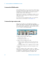
1
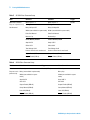
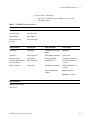
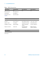
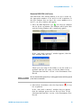
Agilent U4154A Logic
Analyzer
Service Guide
Agilent Technologies
Notices
© Agilent Technologies, Inc. 2013
Manual Part Number
No part of this manual may be reproduced
in any form or by any means (including
electronic storage and retrieval or translation into a foreign language) without prior
agreement and written consent from Agilent Technologies, Inc. as governed by
United States and international copyright
laws.
U4154-97005
Trademark Acknowledgements
Windows and MS Windows are U.S. registered trademarks of Microsoft Corporation.
Windows XP is a U.S. registered trademark
of Microsoft Corporation.
Edition
Fourth edition, February 2013
Available in electronic format only
Agilent Technologies, Inc.
1900 Garden of the Gods Road
Colorado Springs, CO 80907 USA
Warranty
The material contained in this document is provided “as is,” and is subject to being changed, without notice,
in future editions. Further, to the maximum extent permitted by applicable
law, Agilent disclaims all warranties,
either express or implied, with regard
to this manual and any information
contained herein, including but not
limited to the implied warranties of
merchantability and fitness for a particular purpose. Agilent shall not be
liable for errors or for incidental or
consequential damages in connection
with the furnishing, use, or performance of this document or of any
information contained herein. Should
Agilent and the user have a separate
written agreement with warranty
terms covering the material in this
document that conflict with these
terms, the warranty terms in the separate agreement shall control.
Technology Licenses
The hardware and/or software described in
this document are furnished under a
license and may be used or copied only in
accordance with the terms of such license.
computer software” as defined in FAR
52.227-19 (June 1987) or any equivalent
agency regulation or contract clause. Use,
duplication or disclosure of Software is
subject to Agilent Technologies’ standard
commercial license terms, and non-DOD
Departments and Agencies of the U.S. Government will receive no greater than
Restricted Rights as defined in FAR
52.227-19(c)(1-2) (June 1987). U.S. Government users will receive no greater than
Limited Rights as defined in FAR 52.227-14
(June 1987) or DFAR 252.227-7015 (b)(2)
(November 1995), as applicable in any
technical data.
Safety Notices
CAUTION
A CAUTION notice denotes a hazard. It calls attention to an operating procedure, practice, or the like
that, if not correctly performed or
adhered to, could result in damage
to the product or loss of important
data. Do not proceed beyond a
CAUTION notice until the indicated
conditions are fully understood and
met.
WA R N I N G
A WARNING notice denotes a
hazard. It calls attention to an
operating procedure, practice, or
the like that, if not correctly performed or adhered to, could result
in personal injury or death. Do not
proceed beyond a WARNING
notice until the indicated conditions are fully understood and met.
Restricted Rights Legend
If software is for use in the performance of
a U.S. Government prime contract or subcontract, Software is delivered and
licensed as “Commercial computer software” as defined in DFAR 252.227-7014
(June 1995), or as a “commercial item” as
defined in FAR 2.101(a) or as “Restricted
2
U4154A Logic Analyzer Service Guide
Additional Safety Notices
This apparatus has been designed and tested in accordance with IEC Publication 1010,
Safety Requirements for Measuring Apparatus, and has been supplied in a safe condition.
This is a Safety Class I instrument (provided with terminal for protective earthing). Before
applying power, verify that the correct safety precautions are taken (see the following
warnings). In addition, note the external markings on the instrument that are described
under "Safety Symbols."
Warnings
•
Before turning on the instrument, you must connect the protective earth terminal of the
instrument to the protective conductor of the (mains) power cord. The mains plug shall
only be inserted in a socket outlet provided with a protective earth contact. You must
not negate the protective action by using an extension cord (power cable) without a
protective conductor (grounding). Grounding one conductor of a two-conductor outlet
is not sufficient protection.
•
Only fuses with the required rated current, voltage, and specified type (normal blow,
time delay, etc.) should be used. Do not use repaired fuses or short-circuited
fuseholders. To do so could cause a shock or fire hazard.
•
If you energize this instrument by an auto transformer (for voltage reduction or mains
isolation), the common terminal must be connected to the earth terminal of the power
source.
•
Whenever it is likely that the ground protection is impaired, you must make the
instrument inoperative and secure it against any unintended operation.
•
Service instructions are for trained service personnel. To avoid dangerous electric
shock, do not perform any service unless qualified to do so. Do not attempt internal
service or adjustment unless another person, capable of rendering first aid and
resuscitation, is present.
•
Do not install substitute parts or perform any unauthorized modification to the
instrument.
•
Capacitors inside the instrument may retain a charge even if the instrument is
disconnected from its source of supply.
•
Do not operate the instrument in the presence of flammable gasses or fumes.
Operation of any electrical instrument in such an environment constitutes a definite
safety hazard.
•
Do not use the instrument in a manner not specified by the manufacturer.
To clean the instrument
If the instrument requires cleaning: (1) Remove power from the instrument. (2) Clean the
external surfaces of the instrument with a soft cloth dampened with a mixture of mild
detergent and water. (3) Make sure that the instrument is completely dry before reconnecting it to a power source.
Safety Symbols
!
Instruction manual symbol: the product is marked with this symbol when it is
necessary for you to refer to the instruction manual in order to protect against
damage to the product.
Hazardous voltage symbol.
Earth terminal symbol: Used to indicate a circuit common connected to grounded
chassis.
U4154A Logic Analyzer Service Guide
3
Agilent U4154A Logic Analyzer - At a Glance
The U4154A logic analyzer module is a 136 channel state
and timing analyzer that provides 2.5 Gb/s state logic
analysis and up to 5.0 GHz timing analysis. The U4154A has
2 M to 200 M sample memory depth (depending on the
option chosen).
The U4154A logic analyzer module uses 4 pod cables. Each
of these pod cables has 2 90- pin probe connector pods
making it a total of eight pods per U4154A module. Each of
these pods contain 17 channels, out of which 16 are data
channels and 1 channel is bonus bit or clock channel.
Features
Some of the main features of the U4154A are as follows:
• 136 channels per module
• Expandable to 272 channels (as a 2- card set in the AXIe
chassis).
• 2.5 Gb/s maximum state acquisition speed.
• “Eye scan” feature.
• A state sampling clock with four qualifiers.
• 2.5 GHz timing analysis on all channels and 5.0 GHz
timing analysis in the half channel timing mode.
Service Strategy
The service strategy for this module is the replacement of
defective module/parts. This service guide contains
information for finding a defective assembly by testing and
servicing the U4154A logic analyzer module.
The modules can be returned to Agilent Technologies for all
service work, including troubleshooting. Contact your nearest
Agilent Technologies Sales Office for more details.
Contacting Agilent Technologies
To locate a sales or service office near you, go to
www.agilent.com/find/contactus.
4
U4154A Logic Analyzer Service Guide
Application
This service guide applies to U4154A logic analyzer modules
installed in a M9502A or M9505A AXIe chassis.
U4154A Logic Analyzer Module
The following figure displays the M9502A (2- slot) AXIe
chassis and M9505A 5- slot AXIe chassis.
M9502A and M9505A AXIe Chassis
U4154A Logic Analyzer Service Guide
5
In This Service Guide
This book is the service guide for the U4154A logic analyzer
module.
This service guide has five chapters.
Chapter 1, “General Information” contains information about
the module, lists accessories for the module, gives
specifications and characteristics of the module, and
provides a list of the equipment required for servicing the
module.
Chapter 2, “Preparing for Troubleshooting or Performance
Testing” tells how to prepare the module for use.
Chapter 3, “Testing U4154A Performance” tells how to verify
the U4154A performance with specifications.
Chapter 4, “Calibrating” contains calibration instructions for
the module (if required).
Chapter 5, “Troubleshooting” contains explanations of
self- tests and flowcharts for troubleshooting the module.
Chapter 6, “Returning and Replacing a U4154A Module or its
cables” explains how to replace the module, its circuit board
and cables and how to return these to Agilent Technologies.
6
U4154A Logic Analyzer Service Guide
Contents
Agilent U4154A Logic Analyzer - At a Glance
In This Service Guide
1
6
General Information
Accessories 12
Probing Accessories 12
U4201A Pod Connector Cables
Chassis and software
Specifications
13
15
Preparing for Troubleshooting or Performance Testing
To set up the U4154A module
To test the U4154A module
To clean the module
3
12
12
Characteristics 14
Environmental Characteristics
2
4
18
19
19
Testing U4154A Performance
Perform the Self-Tests
24
Equipment Required for the Performance Test
Assemble the SMA/Flying Lead Test Connectors
Set Up the Test Equipment
25
26
31
Connect the Test Equipment 35
Connect the U4154A Logic Analyzer Pod to the Pulse Generator
Connect the Pulse Generator Output to the Oscilloscope 37
Verify and adjust the pulse generator DC offset 38
Deskew the oscilloscope 39
U4154A Logic Analyzer Service Guide
35
7
Contents
Test the U4154A Module 40
Configure the Logic Analysis System 41
Determine maximum clock rate 46
Adjust sampling positions using Eye Scan
Re-align a stray channel 52
Test Pod 1 54
Test Pod 2 58
Test Pods 3 60
Performance Test Record
4
62
Calibrating
Calibration Strategy
5
48
66
Troubleshooting
To use the flowcharts
68
Self-Test Descriptions 70
PC Board Revision Test 70
Interface FPGA Version Test 70
Interface FPGA Register Test 70
FPGA to FPGA Communication Test 70
SPI Bus Communication Test 70
EEPROM Test 70
Probe ID Read Test 71
Chip Registers Read/Write Test 71
Freq Synth Lock Detect Test 71
Acquisition Chip BIST Test 71
Resource Bus Connection Test 71
Comparator Programming Test 71
Comparator/DAC Test 71
Comparator Delay Test 72
Comparator Zero-Hold Cal Test 72
Comparator Calibrations Test 72
Acquisition Memory Write/Read Test 72
Acquisition Memory Cell Test 72
ATB (AXIe Trigger Bus) Test 73
To run the self tests
74
To exit the test system
To test the cables
6
75
76
Returning and Replacing a U4154A Module or its cables
To remove the U4154A module
8
86
U4154A Logic Analyzer Service Guide
Contents
To remove the logic analyzer cable
86
To install the U4201A logic analyzer cable
To replace the circuit board
87
87
To return the U4154A module or cable for Repair/Exchange
88
Index
U4154A Logic Analyzer Service Guide
9
Contents
10
U4154A Logic Analyzer Service Guide
Agilent U4154A Logic Analyzer
Service Guide
1
General Information
Accessories 12
Chassis and software 12
Specifications 13
Characteristics 14
This chapter lists the accessories and some of the
specifications and characteristics for testing and servicing
the U4154A logic analyzer.
Agilent Technologies
11
1
General Information
Accessories
One or more of the following accessories, sold separately, are
required to set up and operate the U4154A logic analyzer
module for testing and servicing it.
Probing Accessories
For information about probing accessories for logic analyzers
with 90- pin pod connectors, see the Probing Solutions for
Logic Analyzers Catalog, literature part number 5968- 4632E,
available on Agilent’s web site (www.agilent.com).
U4201A Pod Connector Cables
The Agilent U4201A 90- pin pod connector cable is used to
connect the U4154A module with the probes which then
connect to the DUT/SUT. You need four U4201A pod cables
for a U4154A module. Refer to the U4154A Logic Analyzer
Installation Guide to learn more about these cables.
Chassis and software
The U4154A logic analyzer requires:
• M9502A or M9505A Agilent AXIe chassis that provides
slots for installing the U4154A module.
• A host PC which is a laptop or a desktop PC with a PCIe
interface. The host PC connects to the Agilent AXIe
chassis via PCIe interface and is used to host all the
required software components of the U4154A module for
configuring, controlling, and using this module.
• Agilent Logic Analyzer software version 05.00 or higher to
configure, control, and use the U4154A module.
Refer to the U4154A Logic Analyzer Installation Guide to
learn more about AXIe chassis, host PC, and the Logic
Analyzer software installation.
12
U4154A Logic Analyzer Service Guide
General Information
1
Specifications
The specifications are the performance standards against
which the product is tested.
U4154A Logic Analyzer Specifications
Parameter
2.5 Gb/s
mode
Notes
Maximum state data rate
2.5 Gb/s
(DDR, 1.25 GHz clock), specified at probe tip.
1.4 Gb/s
mode
Maximum state data rate
U4154A Logic Analyzer Service Guide
1.4 Gb/s
13
1
General Information
Characteristics
The characteristics are not specifications, but are included
as additional information.
Table 1
14
Characteristics
Characteristic
Value
Maximum Conventional Timing Rate
5.0 GHz, half channel
Channel Count per module
136
Channel Count per 2-Cards Module
272
Memory Depth U4154A Option 002
2 M Samples
Memory Depth U4154A Option 004
4 M Samples
Memory Depth U4154A Option 008
8 M Samples
Memory Depth U4154A Option 016
16 M Samples
Memory Depth U4154A Option 032
32 M Samples
Memory Depth U4154A Option 064
64 M Samples
Memory Depth U4154A Option 100
100 M Samples
Memory Depth U4154A Option 200
200 M Samples
U4154A Logic Analyzer Service Guide
General Information
1
Environmental Characteristics
Table 2
Environmental Characteristics
Probes
Maximum
Input Voltage
± 40 V, CAT I. CAT I = Category I, secondary power line isolated
circuits.
Operating Environment
Temperature
Instrument, 0 °C to 40 °C (+32 °F to 104 °F).
Probe lead sets and cables, 0 °C to 65 °C (+32 °F to 149 °F).
Humidity
Instrument, probe lead sets, and cables, up to 80% relative
humidity at +40 °C (+104 °F), non-condensing.
Altitude
To 3000 m (10,000 ft).
Vibration
Operating: Random vibration 5 to 500 Hz, 10 minutes per axis,
≈0.2 g (rms).
Power
All power supplies required for operating the U4154A logic
analyzer are supplied through the backplane connector in the
Agilent AXIe chassis in which you install the module.
Non-operating: Random vibration 5 to 500 Hz, 10 minutes per
axis, ≈2.41 g (rms); and swept sine resonant search, 5 to 500 Hz,
0.5 g (0-peak),
5 minute resonant dwell at 4 resonances per axis.
Indoor use only.
Pollution Degree 2. Normally only dry non-conductive pollution
occurs. Occasionally a temporary conductivity caused by
condensation may occur.
Storage
Store or ship the logic analyzer in environments within the
following limits:
• Temperature: -40°C to +75°C (-40°F to +167°F).
• Humidity: Up to 90% at 65°C (+149°F).
• Altitude: Up to 15,300 meters (50,000 feet).
Protect the module from temperature extremes which cause
condensation on the instrument.
For a full listing of all specifications and characteristics, see
the Agilent U4154A Logic Analyzer Data Sheet, literature
part number 5990- 7513EN available on Agilent’s web site
(www.agilent.com).
U4154A Logic Analyzer Service Guide
15
1
16
General Information
U4154A Logic Analyzer Service Guide
Agilent U4154A Logic Analyzer
Service Guide
2
Preparing for Troubleshooting or
Performance Testing
To set up the U4154A module 18
To test the U4154A module 19
To clean the module 19
This chapter gives you instructions for preparing the U4154A
logic analyzer module for troubleshooting or servicing it.
Operating Environment
The operating environment is listed on page 15. Note the
non- condensing humidity limitation. Condensation within the
instrument can cause poor operation or malfunction. Provide
protection against internal condensation.
The logic analyzer module will operate at all specifications
within the temperature and humidity range given on
page 15. However, reliability is enhanced when operating the
module within the following ranges:
Temperature: +20°C to +35°C (+68°F to +95°F)
Humidity: 20% to 80% non- condensing
Agilent Technologies
17
2
Preparing for Troubleshooting or Performance Testing
To set up the U4154A module
To set up the U4154A module for troubleshooting/servicing,
you first need to install it in one of the slots of the AXIe
chassis. Then connect the chassis to the host PC via a PCIe
link. On the host PC, install the Logic Analyzer (5.0 or
higher) application to configure and control the U4154A
module. Connect the U4154A module to a probe using the
U4201A pod connector cables.
You can find the detailed instructions for configuring and
installing the U4154A module into the AXIe chassis in the
U4154A Logic Analyzer Installation Guide.
If you don’t have the installation guide, you can find the
latest version on the Internet at www.agilent.com.
On this site, specify “U4154A” in the quick search box. In
the product page’s Technical Support area, select “Manuals &
Guides” to find the Installation Guide.
18
U4154A Logic Analyzer Service Guide
Preparing for Troubleshooting or Performance Testing
2
To test the U4154A module
The U4154A logic analyzer module does not require an
operational accuracy calibration or adjustment. After
installing the module, you can test and use the module.
• If you require a test to verify logic analyzer’s performance
with the specifications, see “Testing U4154A
Performance" on page 21.
• If you require a test to verify correct module operation,
see “To run the self tests" on page 74.
• If the module does not operate correctly, see
“Troubleshooting" on page 67.
To clean the module
• With the AXIe chassis turned off and unplugged, use a
cloth moistened with a mixture of mild detergent and
water to clean the front panel of the module.
• Do not attempt to clean the module’s circuit board.
U4154A Logic Analyzer Service Guide
19
2
20
Preparing for Troubleshooting or Performance Testing
U4154A Logic Analyzer Service Guide
Agilent U4154A Logic Analyzer
Service Guide
3
Testing U4154A Performance
Perform the Self-Tests 24
Equipment Required for the Performance Test 25
Assemble the SMA/Flying Lead Test Connectors 26
Set Up the Test Equipment 31
Connect the Test Equipment 35
Test the U4154A Module 40
Performance Test Record 62
This chapter tells you how to test the performance of the
U4154A logic analyzer against the specifications listed on
page 13.
To ensure the U4154A logic analyzer module is operating as
specified, software tests (self- tests) and a manual
performance test are done. The logic analyzer is considered
performance- verified if all of the software tests and the
manual performance test have passed.
The specifications for the U4154A logic analyzer define a
maximum state data rate at which data can be acquired in
state mode. The manual performance test (maximum state
data rate test) verifies that the logic analyzer meets these
specifications.
AXIe Chassis
You must test the U4154A logic analyzer module in a
M9502A or M9505A AXIe chassis.
Test Strategy
Only specified parameters are tested. Specifications are
listed on page 13. The test conditions defined in this
procedure ensure that the specified parameter is as good as
or better than specifications. No attempt is made to
determine performance which is better than specifications.
Not all channels of the logic analyzer will be tested; a
Agilent Technologies
21
3
Testing U4154A Performance
sample of channels is tested. The calibration laboratory may
choose to elaborate on these tests and test all channels at
their discretion.
NOTE
A U4154A module that is licensed with the -01G option needs to be tested
at an Agilent Service Center. The Service Center has the capability to test
the module at up to the 2.5Gb/s state speed to ensure that the calibration
will remain valid even after upgrading it to the -02G license.
Eye Scan is used to adjust the sampling position on every
channel. Eye scan must be used to achieve maximum state
data rate performance.
The 2.5 Gb/s state logic analyzer will be tested. All eight
pods will be tested, one pod at a time.
The logic analyzer acquires data on both edges of the clock,
so the test frequency is set to half of the acquisition speed.
One-card Module
To perform a complete test on a one- card module, start at
the beginning of the chapter and follow each procedure.
Multi-card Module
To perform a complete test on a multi- card module, perform
the self- tests with the cards connected. Then, remove the
multi- card module from the chassis and configure each card
as a one- card module. Install the one- card modules into the
chassis and perform the performance verification tests on
each card. When the tests are complete, remove the one- card
modules, reconfigure them into their original multi- card
module configuration, reinstall into the chassis and perform
the self- tests again. These steps are necessary to ensure that
the clocks are tested on each module.
Instructions for removing and installing the module can be
found in the installation guide for the chassis or the U4154A
module.
If you don’t have the installation guide for your U4154A
module, you can find the latest version on the Internet at
www.agilent.com.
Test Interval
Test the performance of the U4154A module against its
specifications at two- year intervals.
22
U4154A Logic Analyzer Service Guide
Testing U4154A Performance
3
Test Record Description
A Performance Test Record for recording the results of each
procedure is provided in this chapter. You may want to make
copies of this, and fill- in a copy each time you test the
module.
Test Equipment
A list of the recommended test equipment is provided. You
can use any equipment that satisfies the specifications given.
However, the instructions are written with the presumption
that you are using the recommended test equipment.
U4154A Logic Analyzer Service Guide
23
3
Testing U4154A Performance
Perform the Self-Tests
Once you have connected all the hardware components for
the U4154A module and created a logical module for U4154A
in the Agilent Logic Analyzer application, you are ready to
run the self tests on U4154A.
1 Before performing the self- tests, disconnect all probes
from the logic analyzer module.
2 Select Help->Self-Test... from the main menu. The Analysis
System Self Tests window will appear.
3 In the Select suites list, select U4154A. Then, select All in
the Select tests list.
4 Select Start. This will perform a complete system self- test.
24
U4154A Logic Analyzer Service Guide
3
Testing U4154A Performance
The progress of the self tests is displayed in the Results
area of the window.
5 When the self- tests are complete, check the Results
window to ensure that the Result Summary says that all
tests passed. If all tests did not pass, refer to “To use the
flowcharts" on page 68.
6 Select the Close button to close the Analysis System Self
Tests window.
7 If all module self- tests pass, then record “PASS” in the
“Logic Analysis System Self- Tests” section of the
Performance Test Record (page 62).
Equipment Required for the Performance Test
The following equipment is required for the performance test
procedure.
Table 3
Equipment Required
Equipment
Critical Specification
Recommended Model/Part
Pulse Generator
≥ 1275 MHz, two channels, differential
outputs, 150-180 ps rise/fall time (if
faster, use transition time converters)
Agilent 81134A or equivalent
150 ps Transition Time Converter
(Qty 4)
Required if pulse generator’s rise time Agilent or HP 15435A
is less than 150 ps. (Pulse generator
conditions: Voffset=1V, ΔV=250 mV.)
Required for 81134A or 8133A opt. 003.
Oscilloscope
Bandwidth ≥ 6 GHz
Agilent DSO90604A or equivalent
SMA Coax Cable
(Qty 2)
>18 GHz bandwidth
Agilent or HP 8120-4948
Flying Lead Probe Set
(Qty 2)
no substitute
Agilent E5382A
Male BNC to Female SMA adapters
(Qty 2)
SMA/Flying Lead test connectors, (f)
SMA to (f) SMA to Flying Lead Probe
(Qty 4)
U4154A Logic Analyzer Service Guide
Cambridge Products CP-AD507
(see www.cambridgeproducts.com)
no substitute
See “Assemble the SMA/Flying Lead
Test Connectors" on page 26
25
3
Testing U4154A Performance
Assemble the SMA/Flying Lead Test Connectors
The SMA/Flying Lead test connectors provide a
high- bandwidth connection between the logic analyzer and
the test equipment. The following procedure explains how to
fabricate the four required test connectors.
Table 4
Materials Required for SMA/Flying Lead Test Connectors
Material
Critical Specification
SMA Board Mount Connector
(Qty 8)
Recommended Model/Part
Johnson 142-0701-801
(see www.johnsoncomponents.com)
Pin Strip Header
(Qty 1, which will be separated)
0.100" X 0.100" Pin Strip Header, right
angle, pin length 0.230", two rows,
0.120" solder tails, 2 X 40 contacts
3M 2380-5121TN or similar 2- row with
0.1” pin spacing
SMA 50 ohm terminators
(Qty 2)
Minimum bandwidth 2 GHz
Johnson 142-0801-866 50 ohm Dummy
Load Plug
SMA m-m adapter
(Qty 4)
26
Johnson 142-0901-811 SMA Plug to
Plug or similar
U4154A Logic Analyzer Service Guide
Testing U4154A Performance
3
1 Prepare the pin strip header:
a Cut or cleanly break a 2 x 2 section from the pin strip.
b Trim about 1.5 mm from the pin strip inner leads and
straighten them so that they touch the outer leads.
c Trim about 2.5 mm from the outer leads.
d Using a very small amount of solder, tack each inner
lead to each outer lead at the point where they are
touching.
U4154A Logic Analyzer Service Guide
27
3
Testing U4154A Performance
2 Solder the pin strip to the SMA board mount connector:
a Solder the leads on the left side of the pin strip to the
center conductor of the SMA connector as shown in
the diagram below.
b Solder the leads on the right side of the pin strip to
the inside of the SMA connector’s frame as shown in
the diagram below. Use a small amount of solder.
3 Attach the second SMA board mount connector:
a Re- heat the solder connection made in the previous
step, and attach the second SMA connector, as shown
in the diagram below. Note that the second SMA
connector is upside- down, compared to the first. Add a
little solder to make a good connection.
b Solder the center conductor of the second SMA
connector to the center conductor of the first SMA
connector and the leads on the left side of the pin
strip.
c Rotate the assembly 180 degrees and solder the two
SMA board mount connector frames together.
4 Check your work:
a Ensure that the following four points have continuity
between them: The two pins on the left side of the pin
28
U4154A Logic Analyzer Service Guide
Testing U4154A Performance
3
strip, and the center conductors of each SMA
connector.
b Ensure that there is continuity between each of the
two pins on the right side of the pin strip, and the
SMA connector frames.
c Ensure that there is NO continuity between the SMA
connector center conductor and the SMA connector
frame (ground).
5 Finish creating the test connectors:
a Attach an SMA m- m adapter to one end of each of the
four SMA/Flying Lead test connectors.
b Attach a 50 ohm terminator to the other end of two of
the SMA/Flying Lead test connectors.
U4154A Logic Analyzer Service Guide
29
3
Testing U4154A Performance
c The finished test connector is shown in the pictures
below.
30
U4154A Logic Analyzer Service Guide
Testing U4154A Performance
3
Set Up the Test Equipment
This section explains how to set up the test equipment for
the minimum master- to- master clock time/maximum state
data rate test.
1 Turn on the required test equipment. Let all of the test
equipment and the logic analyzer warm up for 30 minutes
before beginning any test.
2 Set up the pulse generator according to one of the
following tables.
a Set the frequency of the pulse generator:
In this test procedure, the logic analyzer uses both
edges of the clock to acquire data. The test frequency
is half the test clock rate because data is acquired on
both the rising edge and the falling edge of the clock.
Set the frequency to 1250 MHz plus 2% (1275 MHz).
This includes the frequency uncertainty of the pulse
generator, plus a test margin.
For example, if you are using an 8133A pulse
generator, the frequency accuracy is ±0.5% of setting.
If you are using an 81134A pulse generator, the
frequency accuracy is ±0.005% of setting.
b Set the rest of the pulse generator parameters to the
values shown in one of the following tables.
U4154A Logic Analyzer Service Guide
31
3
Testing U4154A Performance
Table 5
81134A Pulse Generator Setup
Main
Channel 2
Channel 1
Trigger
Mode: Pulse/Pattern
Mode: Square ÷ 1
Mode: Square ÷ 1
Disable
Freq: set in previous step.
Timing
Timing
Clock Internal
Delay Ctrl Input Off
Delay Ctrl Input Off
Width: (not available in square mode) Width: (not available in square mode)
Table 6
Pulse Perf: Normal
Pulse Perf: Normal
Deskew: 0 ps
Deskew: 0 ps
Levels: Normal, Custom
Levels: Normal, Custom
Ampl: 0.45 V
Ampl: 0.45 V
Offset: 0.6 V
Offset: 0.6 V
Term Voltage: 0 mV
Term Voltage: 0 mV
Limit to current Levels: unselected
Limit to current Levels: unselected
Output: Enable (LED on)
Output: Enable (LED on)
Output: Enable (LED on)
Output: Enable (LED on)
8133A Pulse Generator Setup
Timebase
Pulse Channel 2
Trigger
Pulse Channel 1
Mode: Int
Mode: Square ÷ 1
Disable (LED on)
Mode: Square
Freq: was set in Delay: (not available in pulse mode)
previous step.
Width: (not available in square
mode)
32
Delay: 0 ps
Width: (not available in square
mode)
Ampl: 0.45 V
Ampl: 0.45 V
Offs: 0.6 V
Offs: 0.6 V
Output: Enable (LED off)
Output: Enable (LED off)
Comp: Normal (LED off)
Comp: Normal (LED off)
Limit: Off (LED off)
Limit: Off (LED off)
Output: Enable (LED off)
Output: Enable (LED off)
U4154A Logic Analyzer Service Guide
Testing U4154A Performance
3
3 Set up the oscilloscope.
a Set up the oscilloscope according to one of the
following tables.
Table 7
DSO90604A Oscilloscope Setup
Setup: Channel 1
Setup: Channel 2
Setup: Channel 3
Setup: Channel 4
On
On
Off
Off
Scale: 50 mV/div
Scale: 50 mV/div
Offset: 600 mV
Offset: 600 mV
Skew: (Set later. See
page 39.)
Skew: 0.0 seconds
Setup: Horizontal
Setup: Trigger
Setup: Acquisition
Setup: Display
Scale: 200 ps
Mode: Edge
Sampling Mode: Real Time,
Normal
Waveforms
Position: 0 s
Source: Channel 1
Memory Depth: Automatic
Connect dots
Reference: Center
Level: 600 mV
Averaging: Enabled
Color Grade: not selected
External 10 MHz Reference
Clock: not selected
Edge: Rising Edge
# of Averages: 16
Infinite Persistence: not
selected
Zoom: not selected
Sweep: Auto
Sampling Rate: Automatic
Waveform Brightness: as
preferred
Sine(x)/x Interpolation:
checked
Grid: On, Quantity: 1
Intensity: as preferred
Measure: Markers
Mode: Manual placement
All else: (n/a)
U4154A Logic Analyzer Service Guide
33
3
Testing U4154A Performance
Table 8
54855A Oscilloscope Setup
Setup: Channel 1
Setup: Channel 2
Setup: Channel 3
Setup: Channel 4
On
On
Off
Off
Scale: 100 mV/div
Scale: 100 mV/div
Offset: 600 mV
Offset: 600 mV
Skew: (Set later. See
page 39.)
Skew: 0.0 seconds
Setup: Horizontal
Setup: Trigger
Setup: Acquisition
Setup: Display
Scale: 200 ps
Mode: Edge
Sampling Mode: Real Time
Waveforms
Position: 0 s
Source: Channel 1
Memory Depth: Automatic
Connect dots: checked
Reference: Center
Level: 600 mV
Sampling Rate: Automatic
Display Mode: Normal
Roll Mode: not selected
Edge: Rising Edge
Sine(x)/x Interpolation:
checked
Persistence: Minimum
Delayed: not selected
Sweep: Auto
Averaging: Enabled,
# of Averages: 16
Grid: On, Quantity: 1,
Intensity: as preferred
Measure: Markers
Mode: Manual placement
All else: (n/a)
34
U4154A Logic Analyzer Service Guide
Testing U4154A Performance
3
Connect the Test Equipment
Connect the U4154A Logic Analyzer Pod to the Pulse Generator
1 Connect Transition Time Converters (if required - see
page 25) to each of the four outputs of the pulse
generator: Channel 1 OUTPUT, Channel 1 OUTPUT,
Channel 2 OUTPUT, Channel 2 OUTPUT.
2 Connect the two SMA/Flying Lead test connectors (see
“Assemble the SMA/Flying Lead Test Connectors" on
page 26) with 50 ohm terminators to the Transition Time
Converters at the pulse generator Channel 1 OUTPUT and
Channel 1 OUTPUT. (If Transition Time Converters are
not required, connect the SMA/Flying Lead test
connectors directly to the pulse generator outputs.)
3 Connect the two SMA/Flying Lead test connectors without
50 ohm terminators to the Transition Time Converters at
the pulse generator Channel 2 OUTPUT and Channel 2
OUTPUT. (If Transition Time Converters are not required,
connect the SMA/Flying Lead test connectors directly to
the pulse generator outputs.)
4 Connect one E5382A Flying Lead Probe Set to Pod 2 of
the U4154A logic analyzer. This probe set is used later to
test data on pods 2 to 8.
5 Connect the other E5382A Flying Lead Probe Set to Pod 1
of the U4154A logic analyzer. This probe set is used for
the clock input.
U4154A Logic Analyzer Service Guide
35
3
Testing U4154A Performance
6 Connect the Pod 1 E5382A Flying Lead Probe Set’s CLK
lead to the pin strip of the SMA/Flying Lead connector at
the pulse generator’s Channel 1 OUTPUT.
ground clip
NOTE
Be sure to use the black ground clip (supplied with the E5382A Flying Lead
Probe Set) and orient the leads so that the black clip is connected to one of
the SMA/Flying Lead connector’s ground pins!
7 Connect the Pod 1 E5382A Flying Lead Probe Set’s CLK
lead to the SMA/Flying Lead connector at the pulse
generator’s Channel 1 OUTPUT. Again, be sure to use the
black ground clip and orient the leads so that the black
clip is connected to ground.
8 Connect the Pod 1 E5382A Flying Lead Probe Set’s bits 2
and 10 to the SMA/Flying Lead test connector’s pin strip
connector at the pulse generator’s Channel 2 OUTPUT.
9 Connect the Pod 1 E5382A Flying Lead Probe Set’s bits 6
and 14 to the SMA/Flying Lead test connector’s pin strip
connector at the pulse generator’s Channel 2 OUTPUT.
36
U4154A Logic Analyzer Service Guide
Testing U4154A Performance
3
Connect the Pulse Generator Output to the Oscilloscope
1 Attach Male BNC to Female SMA adapters to Channels 1
and 2 on the oscilloscope.
2 Attach one end of an SMA cable to the Male BNC to
Female SMA adapter on Channel 1 of the oscilloscope.
3 Attach the other end of the SMA cable to the SMA/Flying
Lead connector at the Channel 2 OUTPUT of the pulse
generator.
4 Attach one end of the other SMA cable to the Male BNC
to Female SMA adapter on Channel 2 of the oscilloscope.
5 Attach the other end of the SMA cable to the SMA/Flying
Lead connector at the Channel 2 OUTPUT of the pulse
generator.
U4154A Logic Analyzer Service Guide
37
3
Testing U4154A Performance
Verify and adjust the pulse generator DC offset
1 From the oscilloscope’s main menu, choose Measure >
Markers....
2 In the Markers Setup dialog, select the Manual Placement
mode; then, set marker “Ay” to 475 mV, and set marker
“By” to 725 mV.
3 Observe the waveforms on the oscilloscope display. If they
are not centered within the “Ay” and “By” markers, adjust
the pulse generator’s Channel 2 OFFSET until the
waveforms are centered as well as possible.
(The resolution of the 8133A pulse generator is 20 mV,
and the resolution of the 81134A pulse generator is 10
mV.)
38
U4154A Logic Analyzer Service Guide
3
Testing U4154A Performance
Deskew the oscilloscope
This procedure neutralizes any skew in the oscilloscope’s
waveform display.
1 On the oscilloscope, make sure the Horizontal scale is 200
ps/div. You can do this using the knob in the Horizontal
setup section of the front panel.
2 Select Setup from the menu bar at the top of the display.
3 Select Channel 1.
4 Click Skew </> to deskew Channel 1 and Channel 2 signals
so that both channels cross the horizontal center line at
the same time, at both ends of the eye (both crossings of
the horizontal center line). The horizontal center of the
graticule line is at 600 mV because the vertical offset was
set to 600 mV in the oscilloscope setup described on
page 33.
5 Select Close in the Channel Setup window.
U4154A Logic Analyzer Service Guide
39
3
Testing U4154A Performance
Test the U4154A Module
The following sections explain how to test the maximum
state data rate.
1 Record the U4154A logic analyzer’s model and serial
number in the Performance Test Record (see page 62).
Record your work order number (if applicable) and
today’s date.
2 Record the test equipment information in the “Test
Equipment Used” section of the Performance Test Record.
3 Turn on the AXIe chassis.
NOTE
Before testing the performance of the module, warm-up the logic analyzer
and the test equipment for 30 minutes.
a Plug in the power cord to the power connector on the
rear panel of the AXIe chassis.
b Press the ON/Standby button on the front panel of the
chassis to power on the chassis.
While the logic analyzer is booting, observe for the
following:
• Ensure all of the installed memory is recognized.
• Any error messages.
• Interrupt of the boot process with or without error
message.
4 During initialization, check for any failures.
If an error or an interrupt occurs, refer to the
troubleshooting section.
40
U4154A Logic Analyzer Service Guide
3
Testing U4154A Performance
Configure the Logic Analysis System
1 In the Agilent Logic Analyzer application, choose
File→New. This puts the logic analysis system into its
initial state.
2 Disable all logic analyzers other than the analyzer under
test.
a Select the Overview tab at the bottom of the main
window.
b Click on each unused logic analyzer and select disable.
Only the logic analyzer to be tested should remain
enabled.
U4154A Logic Analyzer Service Guide
41
3
Testing U4154A Performance
3 Set up the bus and signals:
a In the Overview window, select Setup→Bus/Signal... from
the module’s drop- down menu.
b In the Analyzer Setup window, choose the Threshold
NOTE
42
button for Pod 1.
The E5382A probe must be connected to the logic analyzer pod as
described on page 35.
U4154A Logic Analyzer Service Guide
Testing U4154A Performance
3
The Threshold Settings window appears.
c Set the threshold value for Pod 1 of the logic analyzer
to 600 mV. Click Apply to All Other Pods (Excluding
Clocks). Then, click Done to close the dialog.
d Drag the scroll bar all the way to the left.
U4154A Logic Analyzer Service Guide
43
3
Testing U4154A Performance
e Select the Clock Thresholds button.
f
In the Threshold Settings for Clock Channels dialog,
set the Pod 1 clock threshold to Differential.
g Click Done.
The activity indicator will show activity on clock 1.
44
U4154A Logic Analyzer Service Guide
3
Testing U4154A Performance
h The activity indicators now show activity on the
channels that are connected to the pulse generator.
Un- assign all channels. You can do this quickly by
clicking on the left- most check mark and dragging to
the right across all of the other check marks.
i
Click to select channels 2, 6, 10, and 14 as shown in
the picture above.
4 Select the State sampling mode and set the State Clock
options:
a Select the Sampling tab of the Analyzer Setup window.
b Select State - Synchronous Sampling.
5 Set the trigger position and acquisition memory depth:
a Set the Trigger Position to 100% Poststore.
b Set the Acquisition Depth to 128K.
c Set Clk1 to Both edges clocking. The following screen
displays this state clock setting.
U4154A Logic Analyzer Service Guide
45
3
Testing U4154A Performance
Determine maximum clock rate
1 Switch to the Listing window by selecting the Listing tab
at the bottom of the main window.
2 Click the Run Repetitive
toolbar button to start a
repetitive run on the logic analyzer for acquiring data
repeatedly.
Acquired data will start appearing in the Listing window.
3 Start increasing the frequency on the pulse generator by 1
MHz increments while simultaneously observing the logic
analyzer data acquisition status.
4 When the logic analyzer displays an error that the data
could not be displayed, decrease the pulse generator
frequency by 1 MHz.
5 Close the displayed error dialog by clicking OK.
6 Wait for logic analyzer to complete 100 acquisitions at the
new pulse generator frequency without displaying any
error. If an error is displayed, decrease the pulse
generator frequency by 1 MHz and then again wait for
100 acquisitions at this new frequency without any error.
Repeat this step until you get 100 acquisitions without
any error display.
7 Click the Stop
toolbar button to stop the data
acquisition.
46
U4154A Logic Analyzer Service Guide
3
Testing U4154A Performance
Determine PASS/FAIL for the Pulse Generator Frequency test
If you get 100 acquisitions without any error display at a
pulse generator frequency (including uncertainty) greater
than 1250 MHz, then the logic analyzer passes this portion
of the test. For example, a frequency of 1280 MHz - 2%
uncertainty = 1254.4 MHz indicates a PASS result for the
test. Record PASS/FAIL result of this test in the “Pulse
Generator Frequency Test” section of the Performance Test
Record (page 62).
NOTE
If any of tests described later in this chapter fail, decrease the pulse generator
frequency by 1 MHz and wait for logic analyzer to complete 100 acquisitions at this
new pulse generator frequency without displaying any error. Repeat this step until
you get 100 acquisitions without any error display.
Final pulse generator frequency
If the remaining tests described in this chapter PASS, record
the final pulse generator frequency in the “Final Pulse
Generator Frequency” section of the Performance Test Record
(page 62). Recording this final frequency provides a
traceable measurement that is expected to be unique for
each U4154A Logic Analyzer module.
U4154A Logic Analyzer Service Guide
47
3
Testing U4154A Performance
Adjust sampling positions using Eye Scan
1 Select the Eye Scan: Sample Positions and Thresholds...
button.
The Eye Scan - Sample Positions and Threshold
Settings dialog will appear.
2 In the Buses/Signals section of the dialog, ensure that
the check box next to “My Bus 1” is checked.
3 Set the sample position for My Bus 1 signals by dragging
the blue bar for “My Bus 1” to approximately - 3.6 ns.
48
U4154A Logic Analyzer Service Guide
Testing U4154A Performance
3
4 Click the plus sign to expand bus “My Bus 1”.
U4154A Logic Analyzer Service Guide
49
3
Testing U4154A Performance
NOTE
Align the blue bars vertically
Initially, the blue bars will be vertically aligned. After running Eye Scan, the
blue bars will not be vertically aligned because an independent sample
position will be determined for each channel.
1 If the blue bars in the Eye Scan display are not vertically aligned:
a In the “My Bus 1” row, grab the right-most blue bar with the mouse pointer
and move it all the way to the left. Release the mouse button. This will
vertically align all of the blue bars.
2 Using the mouse pointer, grab the blue bar for “My Bus 1” and move it to the
recommended starting position of -3.6 ns. All of the blue bars will follow.
5 Click Edit to display the Edit Measurement dialog box.
50
U4154A Logic Analyzer Service Guide
3
Testing U4154A Performance
6 Select Do full time/voltage scan as the scan dimension.
7 Select the Lock thresholds checkbox and click OK.
8 Select the Run This Measurement button in the Eye Scan -
Sample Positions and Threshold Settings dialog.
9 Ensure that an eye appears for each bit near the
recommended starting position. Depending on your test
setup, the eye position may vary. Any skew between
channel 1 and channel 2 of your pulse generator will
cause the eye position to shift to the left or right in the
Eye scan display. A shift of up to 0.5 ns should be
considered normal. The important point is that your Eye
Scan display should look similar to the picture below
(although it may be shifted left or right), and Eye Scan
must be able to place the blue bars in the eye.
U4154A Logic Analyzer Service Guide
51
3
Testing U4154A Performance
Re-align a stray channel
If the blue bar for a particular bit does not appear in its eye
near the recommended starting position, then do the
following steps to realign the sampling position of the stray
channel. In the following example, the sampling position of
one channel (My Bus 1 [0]) must be realigned with the
sampling position of the other channels.
52
U4154A Logic Analyzer Service Guide
3
Testing U4154A Performance
1 Using the mouse, drag the sample position (blue line) of
the stray channel (channel “My Bus 1 [0]” in the above
example) so that it is in the same eye as the other
channels. The Suggested Position from Eye Scan (green
triangle) will also move to the new eye.
2 Repeat the above step for all the remaining stray
channels.
3 Click the Run This Measurement button in the Eye Scan
- Sample Positions and Threshold Settings dialog. Eye
Scan will recalculate the new sample positions based on
the sample position changes. The following example shows
all sampling positions aligned and in the correct eye.
U4154A Logic Analyzer Service Guide
53
3
Testing U4154A Performance
Test Pod 1
The steps that follow include pass/fail criteria.
Determine PASS/FAIL (1 of 2 tests)
1 PASS/FAIL: If an eye exists near - 3.6 ns for every bit, and
Eye Scan places a blue bar in the narrow eye for each bit,
then the logic analyzer passes this portion of the test.
Record the result in the “Eye Scan locates an eye for each bit”
section of the Performance Test Record (page 62).
2 If an eye does not exist near - 3.6 ns for every bit or Eye
Scan cannot place the blue bar in the narrow eye, then
the logic analyzer fails the test. Record the result in the
“Eye Scan locates an eye for each bit” section of the
Performance Test Record (page 62).
54
U4154A Logic Analyzer Service Guide
3
Testing U4154A Performance
Close the Eye Scan and Analyzer Setup Windows
1 Select OK to close the Eye Scan - Sample Positions and
Threshold Settings dialog.
2 Select OK to close the Analyzer Setup window.
Configure the markers
Data must be acquired before the markers can be configured.
Therefore, you need to run the analyzer to acquire data.
1 Switch to the Listing window by selecting the Listing tab
at the bottom of the main window.
2 Select the Run icon
.
3 Data will appear in the Listing Window upon completion
of the run.
If the data values are not “A”s and “5”s, you may need to
set the sampling positions in different eyes.
U4154A Logic Analyzer Service Guide
55
3
Testing U4154A Performance
4 From the Main Menu, choose Markers→New.
a You can accept the default name for the new marker.
b Change the Position field to Value.
c Select the Occurs... button and create the marker setup
shown below.
Click
here
to add
event
Click
here
to select
“Or”
5 In the Value window, select the Properties... button.
6 In the Value Properties window, select Stop repetitive run
when value is not found.
7 Select OK to close the marker Value Properties window.
8 Select OK to close the marker Value window. The system
will search the display for the occurrences specified.
9 Select OK to close the New Marker window.
56
U4154A Logic Analyzer Service Guide
3
Testing U4154A Performance
Determine PASS/FAIL (2 of 2 tests)
Pass/Fail Point: The Listing window is set up to search for
the appropriate number of A's and 5's in the acquisition. If
the logic analyzer does not detect the correct number of A’s
and 5’s, an error window will appear.
1 Select the Run Repetitive icon
. Let the logic analyzer
run for about one minute. The analyzer will acquire data
and the Listing Window will continuously update.
If the “can’t find occurrence” window appears, then the
logic analyzer fails the test.
Check your test setup. If the failure is not the result of a
problem with the test setup, record the failure in the
“Maximum State Data Rate” section of the Performance Test
Record.
NOTE
Be sure that the black ground clip is making good contact with the ground
pin on the test connector.
2 After about one minute, select the Stop button
to stop
the acquisition.
If the “can’t find occurrence” window does not appear,
then the analyzer passes the test. Record “Pass” in the
“Maximum State Data Rate” section of the Performance Test
Record.
U4154A Logic Analyzer Service Guide
57
3
Testing U4154A Performance
Test the complement of the bits
Now test the logic analyzer using inverted levels (in other
words, complement data).
1 On the pulse generator, in the PULSE setup for CHANNEL
2, select inverted levels:
• On the 81134A pulse generator, select Levels: Inverted.
• On the 8133A pulse generator, select COMP (LED on).
2 Verify the DC offset and adjust it if necessary. See
page 38.
3 Adjust the sampling positions (run Eye Scan). See
page 48.
4 Determine pass or fail (1 of 2 tests). See page 54.
5 Switch to the Listing window by selecting the Listing tab
at the bottom of the main logic analyzer window.
6 Select the Run Repetitive icon
.
7 Determine pass or fail (2 of 2 tests). See page 57.
Test Pod 2
1 Disconnect the E5382A Flying Lead Probe Set from the
pulse generator outputs.
2 Connect the probe set from Pod 2 of logic analyzer to the
pulse generator outputs. (The clock input on Pod 1
remains the clock input when testing Pod 2.)
3 On the pulse generator, in the PULSE setup for CHANNEL
2, return the outputs to normal (non- inverted or
non- complement) levels.
4 Verify the DC offset and adjust it if necessary. See
page 38.
5 In the Overview window, select Setup→Bus/Signal... from
the module’s drop- down menu.
6 Scroll to the right and unassign all Pod 1 bits.
7 Set the Pod 2 threshold to 600 mV (just as you did for
Pod 1 on page 43).
58
U4154A Logic Analyzer Service Guide
3
Testing U4154A Performance
8 Assign bits 2, 6, 10, and 14 of Pod 2.
9 Adjust the sampling positions using Eye Scan. Be sure to
expand “My Bus 1” and use the recommended starting
position noted on page 48. Realign any stray channels if
necessary. See page 52.
10 Determine pass or fail (1 of 2 tests). See page 54.
11 Select OK to close the “Analyzer Setup” window.
12 Switch to the Listing window by selecting the Listing tab
at the bottom of the main logic analyzer window.
13 Select the Run Repetitive icon
.
14 Determine pass or fail (2 of 2 tests). See page 57.
Test the complement of the bits (Pod 2)
1 Test the complement of the bits. See page 58.
U4154A Logic Analyzer Service Guide
59
3
Testing U4154A Performance
Test Pods 3
1 Disconnect the E5382A Flying Lead Probe Set from Pod 2
and connect it to Pod 3 of the logic analyzer. (The clock
input on Pod 1 is used when testing Pod 3.)
2 In the Buses/Signals setup dialog, set the Pod 1 clock
threshold to Differential:
a Drag the scroll bar all the way to the left.
b Select the Clock Thresholds button.
c In the Threshold Settings for Clock Channels dialog, set
the Pod 1 clock threshold to Differential.
Click Done.
60
U4154A Logic Analyzer Service Guide
Testing U4154A Performance
3
The activity indicator will show activity on clock 1.
3 Set the State Clock options:
a For State Clock, select Pod 1 Clock and Both edges.
4 Perform the normal and complement tests for Pod 3,
changing the connection to the pod, setting thresholds,
making channel assignments, etc., as appropriate.
Repeat the above steps for testing pods 4 to 8. Upon
completion, the logic analyzer is completely tested.
Conclude the State Mode Tests
Do the following steps to properly shut down the logic
analyzer session after completing the state mode tests.
1 End the test.
a From the Main Menu, choose File→Exit. At the dialog
“Do you want to save the current configuration?” select
No.
Ending and restarting the logic analysis session will
re- initialize the system.
b Disconnect all cables and adapters from the pulse
generator and the oscilloscope.
U4154A Logic Analyzer Service Guide
61
3
Testing U4154A Performance
Performance Test Record
LOGIC ANALYZER MODEL NO. (circle one): U4154A
Logic Analyzer Serial No.
Work Order No.
Date:
Recommended Test Interval - 2 Year/4000 hours
Recommended next testing:
TEST EQUIPMENT USED
Pulse Generator Model No.
Oscilloscope Model No.
Pulse Generator Serial No.
Oscilloscope Serial No.
Pulse Generator Calibration Due Date:
Oscilloscope Calibration Due Date:
MEASUREMENT UNCERTAINTY
Clock Rate
Pulse Generator Frequency Accuracy:
81134A: ±0.005% of setting.
8133A: ±0.5% of setting.
2% = uncertainty + at least 1% test margin.
Setting
1250 MHz + 2% = 1275 MHz
TEST RESULTS
Logic Analysis System Self-Tests (Pass/Fail):
Performance Test: Maximum State Data Rate
Pulse Generator Settings
Freq: 1250 MHz plus 2% (1275 MHz).
Square wave.
Pulse Generator Frequency Test (Pass/Fail)
Final Pulse Generator Frequency
Test Criteria
Test 1 of 2
Eye Scan locates an eye for each bit
Test 2 of 2
Correct number of occurrences
detected
Normal
Normal
Complement
Complement
Pod 1 Results (pass/fail):
Pod 2 Results (pass/fail):
62
U4154A Logic Analyzer Service Guide
Testing U4154A Performance
3
TEST RESULTS
Normal
Complement
Normal
Complement
Pod 3 Results (pass/fail):
Pod 4 Results (pass/fail):
Pod 5 Results (pass/fail):
Pod 6 Results (pass/fail):
Pod 7 Results (pass/fail):
Pod 8 Results (pass/fail):
U4154A Logic Analyzer Service Guide
63
3
64
Testing U4154A Performance
U4154A Logic Analyzer Service Guide
Agilent U4154A Logic Analyzer
Service Guide
4
Calibrating
Calibration Strategy 66
This chapter gives you instructions for calibrating the
U4154A logic analyzer.
Agilent Technologies
65
4
Calibrating
Calibration Strategy
The U4154A logic analyzer does not require any periodic
adjustments or calibration by the user to ensure operational
accuracy.
However, Agilent recommends that performance of the
U4154A logic analyzer be tested against its specifications at
two- year intervals. This testing is required in order to obtain
calibration certification.
You can refer to Chapter 3, “Testing U4154A Performance to
find detailed information on how to test the performance of
the U4154A logic analyzer.
66
U4154A Logic Analyzer Service Guide
Agilent U4154A Logic Analyzer
Service Guide
5
Troubleshooting
To use the flowcharts 68
To run the self tests 74
Self-Test Descriptions 70
To exit the test system 75
To test the cables 76
This chapter provides instructions for troubleshooting a
U4154A module that is not operating correctly.
The troubleshooting consists of flowcharts, self- test
instructions, and a cable test.
If you suspect a problem, start at the top of the first
flowchart. During the troubleshooting instructions, the
flowcharts will direct you to perform the self- tests or the
cable test.
The service strategy for the U4154A module is the
replacement of defective assemblies. You can return this
module to Agilent Technologies for all service work,
including troubleshooting. Contact your nearest Agilent
Technologies Sales Office for more details.
CAUTION
Electrostatic discharge can damage electronic components. Use
grounded wrist-straps and mats when you perform any service to
this instrument or to the modules in it.
Agilent Technologies
67
5
Troubleshooting
To use the flowcharts
Flowcharts are the primary tool used to isolate defective
assemblies. The flowcharts refer to other tests to help isolate
the problem. The circled numbers on the charts indicate
connections with the other flowchart. Start your
troubleshooting at the top of the first flowchart.
Figure 1
68
Troubleshooting Flowchart 1
U4154A Logic Analyzer Service Guide
Troubleshooting
Figure 2
5
Troubleshooting Flowchart 2
U4154A Logic Analyzer Service Guide
69
5
Troubleshooting
Self-Test Descriptions
The self- tests for U4154A logic analyzer identify the correct
operation of major functional areas in the U4154A module.
PC Board Revision Test
This tests that the FPGA is communicating with the
backplane and that the board under test is a supported
version.
Interface FPGA Version Test
This test verifies that the FPGA program is a version that
the software can use. This is necessary because new features
will be added to the U4154A that will require both new
software and new FPGA bits.
Interface FPGA Register Test
The purpose of this test is to verify that the backplane
interface can communicate with the backplane FPGA. The
FPGA must be working before any of the other circuits on
the board will work. Also, the FPGA generates the board ID
code that is returned to identify the module and slot.
FPGA to FPGA Communication Test
This test is only run if there are two or more U4154A logic
analyzer cards installed in a chassis and connected together
with the flex cables. The purpose of this test is to verify
that the FPGAs can drive and receive the signals correctly.
SPI Bus Communication Test
The purpose of this test is to verify communications over the
SPI bus from the Interface FPGA to various devices attached
to the SPI bus.
EEPROM Test
The purpose of this test is to verify:
• The address and data paths to the EEPROM.
• That each cell in the EEPROM can be programmed high
and low.
70
U4154A Logic Analyzer Service Guide
5
Troubleshooting
• That individual locations can be independently addressed.
• The EEPROM can be block erased.
Probe ID Read Test
The purpose of this test is to verify that the Probe ID values
can be correctly read and to verify the functionality of the
Digital to Analog Converter by testing the two Probe ID DAC
outputs at various voltage levels.
Chip Registers Read/Write Test
The purpose of this test is to verify that each bit in each
register of the Analysis chip can be written with a 1 and 0
and read back again. The test also verifies that a chip reset
sets all registers to their reset condition (all 0s for most
registers).
Freq Synth Lock Detect Test
This test determines if all the voltage- controlled oscillators
(VCOs) are working properly.
Acquisition Chip BIST Test
Tests the Timing Zoom memory and other internal memories
on the acquisition chip.
Resource Bus Connection Test
This test is only run if there are two or more U4154A logic
analyzer cards in adjacent slots in a chassis.
This test verifies whether or not the flex cables are squarely
and firmly inserted into the connectors.
Comparator Programming Test
The purpose of this test is to verify the programming path
to each of the comparators.
Comparator/DAC Test
This test is executed only if all probes are detached.
U4154A Logic Analyzer Service Guide
71
5
Troubleshooting
This test uses the pod, bonus, and calibration DACs, the
calibration oscillator (implemented in the interface FPGA),
the comparators, the connections between the comparators
and the Analysis chip, and the activity indicators in the
Analysis chip. We verify that we can use the DACs to control
the data input to the comparators. We verify that each
comparator data channel produces output. We verify that
each comparator output is connected to each ASIC data
input.
Comparator Delay Test
The comparator delay test verifies the integrity of all the
delay line elements for each delay line in the comparators.
Each delay line consists of 11 delay elements. When set for
maximum delay, all 11 elements are connected in series. If
any element is faulty, then data will not propagate through
the comparator. If this is the only test failing, then it is
almost certainly a bad comparator.
Comparator Zero-Hold Cal Test
Tests the delay elements for each delay line in the
comparators. It tests that each delay line can increase its
delay in a linear way through a range of delay values.
Comparator Calibrations Test
The purpose of this test is to verify that each of the
comparator one- time calibrations can successfully be
performed. This verifies that all of the calibration circuitry
and components are within the tolerance limits required for
proper calibration. This test is executed only if all probes
are detached.
Acquisition Memory Write/Read Test
This test checks that each acquisition chip can write data to
DDR acquisition memory and read the same data back.
Acquisition Memory Cell Test
Tests every bit of the DDR acquisition memory. The test
verifies that every bit can be written to 0 and written to 1
and read back accurately.
72
U4154A Logic Analyzer Service Guide
Troubleshooting
5
ATB (AXIe Trigger Bus) Test
This test verifies the ATB signal connections between the
acquisition chips, the interface FPGA and the two 8- bit
transceiver chips.
U4154A Logic Analyzer Service Guide
73
5
Troubleshooting
To run the self tests
You can run self tests on the U4154A module to verify if the
module is operating correctly. Before running self tests,
ensure that:
• you have connected all the hardware components for the
U4154A module
• created a logical module for U4154A in the Agilent Logic
Analyzer application.
• disconnected all probes from the logic analyzer module.
You use the Analysis System Self Tests window to run self
tests. Refer to the topic “Perform the Self- Tests" on page 24
to know how to run these tests.
74
U4154A Logic Analyzer Service Guide
Troubleshooting
5
If all tests did not pass, refer to “To use the flowcharts" on
page 68.
To exit the test system
1 Close the self- test window. No additional actions are
required.
U4154A Logic Analyzer Service Guide
75
5
Troubleshooting
To test the cables
This test allows you to functionally verify U4201A logic
analyzer cables and Agilent E5379A probes.
Table 9
Equipment Required to Test Cables
Equipment
Critical Specification
Recommended Part
Stimulus Board
No Substitute
16760-60001
Differential Probes
No Substitute
E5379A (Qty 2)
1 Connect the U4154A logic analyzer to the stimulus board.
a Connect the Agilent E5379A 90- pin differential probes
to the logic analyzer cable (also called “Pods”) to be
tested. Start with Pods 1 and 2.
b Connect the E5379A probe from logic analyzer Pod 1 to
connector “Pod 4” on the stimulus board.
c Connect the E5379A probe from logic analyzer Pod 2 to
connector “Pod 5” on the stimulus board.
d Connect the stimulus board power supply output to the
stimulus board power supply connector J82.
e Plug in the stimulus power supply to line power. The
green LED DS1 should illuminate showing that the
stimulus board is active.
Pod 1
Pod 2
Pod 4
connector
76
Pod 5
connector
U4154A Logic Analyzer Service Guide
5
Troubleshooting
2 Set up the stimulus board
a Configure the oscillator select switch S1 according to
the following settings:
• S1 0 (Off).
• S2 1 (On).
• S3 0 (Off).
• Int.
b Configure the data mode switch S4 according to the
following settings:
• Even.
• Count.
c Press the Resynch VCO button, then the Counter RST
(Counter Reset) button.
3 In the Agilent Logic Analyzer application, choose
File→New. This puts the logic analysis system into its
initial state.
U4154A Logic Analyzer Service Guide
77
5
Troubleshooting
4 Disable all analyzers except the one being tested. This
simplifies the instructions and makes module initialization
faster.
a Select the Overview tab at the bottom of the main
window.
b Click on each unused logic analyzer and select disable.
Only the logic analyzer to be tested should remain
enabled.
78
U4154A Logic Analyzer Service Guide
Troubleshooting
5
5 Set up the bus:
a In the Overview window, select Setup -> Bus/Signal... from
the module’s drop- down menu.
b Scroll if necessary to view the pods you are testing.
c Verify that the pod threshold buttons say “Threshold:
Differential”, as shown above. If they don’t, make sure
the correct probes (E5379A) are attached to pods 1
and 2. The threshold is set to Differential automatically
when E5379A probes are attached.
U4154A Logic Analyzer Service Guide
79
5
Troubleshooting
d Channels 7 through 0 are already assigned by default.
Assign pod 2 channels 15 through 0 and pod 1
channels 15 through 8 by clicking and dragging from
the left- most channel box to the right- most channel
box. Your display should look like the lower picture
when you are done.
6 Select the State sampling mode and set the State Clock
options:
a Select the Sampling tab of the Analyzer Setup window.
b Select State - Synchronous Sampling.
c For State Clock, select Pod A1 Clock and Both edges.
7 Set the trigger position and acquisition memory depth:
a Set the Trigger Position to 100% Poststore.
b Set the Acquisition Depth to 8K.
80
U4154A Logic Analyzer Service Guide
5
Troubleshooting
8 Adjust sampling positions:
a Select the Eye Scan: Thresholds and Sample Positions button.
The Eyescan - Sample Positions dialog will appear.
b In the “Buses/Signals” section of the Eyescan - Sample
Positions dialog, make sure the check box next to “My
Bus 1” is checked.
c Click Edit and select the Do time scan only option as the
scan dimension and the Lock Thresholds checkbox.
d Select the Run This Measurement button in the Eyescan -
Sample Positions dialog.
U4154A Logic Analyzer Service Guide
81
5
Troubleshooting
e Make sure the sampling positions are set properly, and
re- align any stray channels if necessary.
f
Select OK to close the Eyescan - Sample Positions window.
g Select OK to close the Analyzer Setup window.
9 Switch to the Listing window by selecting the Listing tab
at the bottom of the main window.
10 Select the Run icon
. The listing should look similar to
the figure below when you scroll down a bit.
Scroll down at least 256 samples to verify the data. My
Bus 1 shows four 8- bit binary counters decrementing by 1.
If the listing does not look similar to the figure, there is a
possible problem with the cable or probe. Cause for cable
test failures include:
• Open channel.
• Channel shorted to a neighboring channel.
• Channel shorted to either ground or a supply voltage.
If the test data is not correct, then perform the following
step to isolate the failure.
11 Verify the failure:
a Swap the E5379A probes so that the pod 1 cable
remains connected to the stimulus board’s pod 4
connector and the pod 2 cable remains connected to
82
U4154A Logic Analyzer Service Guide
5
Troubleshooting
the stimulus board’s pod 5 connector — just using
different probes.
b Select the Run icon
.
If the failure is the same (that is, the error follows the
cable) then the cable is faulty.
If the failure switches pods (that is, the error follows the
E5379A probe) the probe is faulty.
12 Repeat the cable test for pods 3 and 4:
a Connect the logic analyzer’s pod 3 cable to the
stimulus board’s pod 4 connector.
b Connect the logic analyzer’s pod 4 cable to the
stimulus board’s pod 5 connector.
c In the Buses/Signals tab of the Analyzer Setup window,
assign the pod 3 and 4 channels to “My Bus 1”.
d In the Sampling tab of the Analyzer Setup window, for
State Clock, select Both edges.
e Adjust sampling positions.
f
Select the Run icon
. In the Listing window, check
at least 256 samples for failures; if necessary, verify
any failures by swapping the E5379A probes.
13 Repeat the cable test (step12) for pod pairs 5 and 6 and
7 and 8 connecting the odd pod cable to the stimulus
board’s pod 4 connector and the even pod cable to the
stimulus board’s pod 5 connector:
Return to the troubleshooting flowchart.
U4154A Logic Analyzer Service Guide
83
5
84
Troubleshooting
U4154A Logic Analyzer Service Guide
Agilent U4154A Logic Analyzer
Service Guide
6
Returning and Replacing a U4154A
Module or its cables
To remove the U4154A module 86
To remove the logic analyzer cable 86
To install the U4201A logic analyzer cable 87
To replace the circuit board 87
To return the U4154A module or cable for Repair/Exchange 88
This chapter contains the instructions for removing and
replacing the U4154A logic analyzer module, and the probe
cables of the module as well as the instructions for
returning defective parts to Agilent Technologies.
CAUTION
Turn off the AXIe chassis before installing, removing, or replacing a
module in the chassis.
The enclosure surface of the U4154A module may become hot
during use. If you need to remove the module, first power down the
AXIe chassis, allow the module to cool, and then pull the module out
of the chassis.
CAUTION
Electrostatic discharge can damage electronic components. Use
grounded wriststraps and mats when performing any service to this
module.
Agilent Technologies
85
6
Returning and Replacing a U4154A Module or its cables
To remove the U4154A module
If the U4154A module or any of its parts are faulty, remove
the faulty module from the AXIe chassis, return it to Agilent
Technologies for repair/exchange. On getting a replaced
module, install it in the AXIe chassis.
Instructions for removing or installing the module into the
AXIe chassis can be found in the U4154A Logic Analyzer
Installation Guide.
If you don’t have the installation guide, you can find the
latest version on the Internet at www.agilent.com.
To remove the logic analyzer cable
There are four cables for each U4154A logic analyzer
module. One cable is for pods 1 and 2, the other cable is for
pods 3 and 4, and so on till pod 8 of the U4154A module.
The following figure displays three cables attached to pods 3,
4, 5, 6, 7, and 8 of the U4154A module.
To remove the logic analyzer cable:
1 Remove power from the AXIe chassis
g Turn off the chassis.
h Disconnect the power cord.
2 Remove the logic analyzer pod cable.
a Remove the two thumb screws that secure the logic
analyzer cable to the pods in the front panel of the
module.
b Disengage thumb screws completely from the module.
3 Pull the cable straight out from the front panel of the
module.
If the logic analyzer cable is faulty, return it to Agilent
Technologies for repair/exchange or order a new cable which
is available as a replaceable part, and follow the next
procedure to install the replaced logic analyzer cable.
86
U4154A Logic Analyzer Service Guide
6
Returning and Replacing a U4154A Module or its cables
To install the U4201A logic analyzer cable
Perform the following steps to connect the new/replaced
logic analyzer cable to the front panel of the U4154A
module.
1 Attach cable connector to the pod input on the front
panel of the module.
2 Tighten the two thumb screws on both sides of the
U4201A cable to retain the cable tightly inside the
relevant pod input. Do not over tighten the thumb screws.
Hand tightening is recommended or maximum torque of
3in- lb.
I
To replace the circuit board
If the circuit board of the U4154A module is found faulty,
perform the following steps to get it repaired/replaced.
1 Remove the logic analyzer cables using the “To remove the
logic analyzer cable” procedure on page 86.
2 Remove the U4154A module with the faulty circuit board
from the AXIe chassis. Refer to the U4154A Logic
Analyzer Installation Guide to learn how to remove the
module from chassis.
3 Send the U4154A module to Agilent Technologies to
repair or replace the faulty circuit board with a new
circuit board.
U4154A Logic Analyzer Service Guide
87
6
Returning and Replacing a U4154A Module or its cables
To return the U4154A module or cable for Repair/Exchange
Before returning the U4154A module or a logic analyzer
cable to Agilent Technologies, contact your nearest Agilent
Technologies Sales Office for additional details. Information
on contacting Agilent can be found at www.agilent.com.
1 Write the following information on a tag and attach it to
the module/cable.
• Name and address of owner.
• Model number.
• Serial number.
• Description of service required or failure indications.
2 Remove accessories from the module.
Only return accessories to Agilent Technologies if they are
associated with the failure symptoms.
3 Package the module/cable.
You can use either the original shipping containers, or
order materials from an Agilent Technologies sales office.
CAUTION
For protection against electrostatic discharge (ESD), package the
module in ESD-safe material.
4 Seal the shipping container securely, and mark it
FRAGILE.
88
U4154A Logic Analyzer Service Guide
Index
A
M
accessories, 12
acquisition, 70
Agilent,contact information, 4
module
clean, 19
remove, 86
test, 19
multi-card module
test, 22
C
cable
install, 87
remove, 86
test E5379A cable, 76
calibrating
see also testing performance
calibration, 65
strategy, 66
characteristics, 14
environmental, 15
chassis, 12
circuit board
replace, 87
clean module, 19
cleaning the instrument, 3
connectors, test, 26
contacting Agilent, 4
E
environment
characteristics, 15
operating, 17
equipment
test, 23
eye finder
adjusting, 48
eye scan, 48
F
features, 4
flowcharts, 68
G
O
one-card module
configure, 18
test, 22
operating
environment, 17
P
performance
testing, 21
probing accessories, 12
R
remove
logic analyzer cable, 86
module, 86
replace
circuit board, 87
replacing module, 85
return module, 88
S
sales office, 4
self-test, 24, 74
description, 70
service office, 4
set up
one-card module, 18
specifications, 13
storage, 15
general information, 11
T
I
test
connectors, 26
E5379A cables, 76
equipment, 23
interval, 22
install
logic analyzer cable, 87
instrument, cleaning the, 3
U4154A Logic Analyzer Service Guide
module, 19
multi-card module, 21
one-card module, 21
performance record, 62
record description, 23
self-test, 24, 74
strategy, 21
testing performance, 21
equipment, 23
interval, 22
multi-card module, 22
test record, 62
troubleshooting, 67
89
Index
90
U4154A Logic Analyzer Service Guide