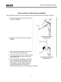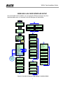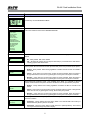
1
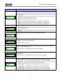
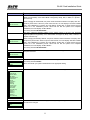
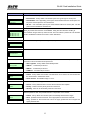
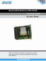
WLAN CARD INSTALLATION GUIDE
For printer models:
GL 4xxe Series
Read this Installation Guide before and during the installation
of the above accessory. Keep this Installation Guide handy for
future reference.
WLAN Card Installation Guide
1 General
1.1 Important information
This quick guide provides important information on how to setup your
new SATO product.
Be sure to read this quick guide thoroughly before using this printer. It is
an integral part of the product and should be kept in the immediate
vicinity of the device and available to the operating staff.
1.2 Limitation of liability
All information in this manual have been compiled under due
consideration of federal standards and regulations.
The manufacturer will not be held liable for damage resulting from:
z Disregarding these instructions
z Unintended use of the printer
z Unauthorized technical modifications
z Use of unapproved spare parts
z Use of unapproved consumables
FCC WARNING
Changes or modifications not expressly approved by the party responsible for
compliance could void the user’s authority to operate the equipment.
NOTICE
This equipment has been tested and found to comply with the limits for a
Class B digital device, pursuant to part 15 of the FCC Rules. These limits
are designed to provide reasonable protection against harmful
interference in a residential installation.
This equipment generates, uses and can radiate radio frequency energy
and, if not installed and used in accordance with the instructions, may
cause harmful interference to radio communications. However, there is
no guarantee that interference will not occur in a particular installation.
2
WLAN Card Installation Guide
1.3 Explanation of symbols
This instruction manual uses various warning icons to help you
understand the safe operation of your printer. Explanations of the
icons are below.
WARNING!
Indicates neglectful or erroneous use may cause
irreparable damage to the product, serious injury to
the operator, or worse.
CAUTION!
Indicates a specific point where caution should be
used. The graphic within the triangle will indicate the
specific issue, i.e.; the sign on the left indicates a
caution for potential electrical shock.
CAUTION!
Indicates a potentially hazardous situation which,
if not avoided, may result in damage to your
product or host equipment.
NOTE!
Emphasizes useful tips or recommendations for
efficient and smooth operation of your printer.
3
WLAN Card Installation Guide
1.4
Contact and Document Information
SATO GROUP OF COMPANIES
.
International Headquarters
Americas
SATO INTERNATIONAL PTE. LTD
438A Alexandra Road #05-01/04,
Alexandra Technopark, Singapore 119967
Phone: 65-6271-2122 Fax : 65-6271-2151
Email: [email protected]
SATO INTERNATIONAL AMERICA, INC.
(Regional HQ)
10350 Nations Ford Road Suite A,
Charlotte, NC 28273
Phone: 1-704-644-1650 Fax: 1-704-644-1662
Email: [email protected]
Americas
SATO AMERICA, INC.
10350 Nations Ford Road Suite A,
Charlotte, NC 28273
Phone: 1-704-644-1650 Fax: 1-704-644-1662
Email: [email protected]
SATO LABELING SOLUTIONS AMERICA, INC.
1140 Windham Parkway, Romeoville, Illinois 60446
Phone: 630-771-4200 Fax : 630-771-4210
Email: [email protected]
Horticultural Division
930 Jimmy Ann Drive
Daytona Beach, FL 32117
Phone: 1-386-274-5566 Fax: 1-386-274-5599
Europe
SATO INTERNATIONAL EUROPE N.V.
(Regional HQ)
Leuvensesteenweg 369, 1932 Sint-Stevens-Woluwe, Brussels, Belgium
Phone: 32(0)-2-788-80-00 Fax: 32(0)-2-788-80-80
Email: [email protected]
SATO UK LTD
Valley Road, Harwich, Essex England Co12 4RR,
United Kingdom
Phone: 44-1255-240000 Fax : 44-1255-240111
Email : [email protected]
SATO LABELLING SOLUTIONS EUROPE GmbH
Ersheimer Straße 71,
69434 Hirschhorn, Germany
Phone: 49-6272-9201-324 Fax: 49-6272-9201-399
SATO POLSKA SP Z O.O.
Ul. Wroclawska 123, 55-015 Radwanice
K/Wroclawia, Poland
Phone: 48-71-381-03-60 Fax: 48-71-381-03-68
Email: [email protected]
SATO FRANCE SAS
Parc D'Activities - Rue Jacques Messager - 59175 Templemars, France
Phone: 33-3-20-62-96-40 Fax: 33-3-20-62-96-55
SATO IBERIA S.A.
Dels Corrals Nous, 35-39, Pol. Can Roqueta,
08202 - Sabadell, Barcelona, Spain
Phone: 34-93-492-5750 Fax : 34-93-786-3451
Asia Pacific & Oceania
SATO INTERNATIONAL ASIA PACIFIC PTE. LTD.
(Regional HQ)
438A Alexandra Road #05-01/04,
Alexandra Technopark, Singapore 119967
Phone : 65-6271-5300 Fax : 65-6273-6011
Email: [email protected]
SATO AUTO-ID MALAYSIA SDN. BHD.
No.25, Jalan Pemberita U1/49, Temasya
Industrial Park
Section U1, 40150 Shah Alam,
Selangor Darul Ehsan, Malaysia
Phone: 60-3-7620-8901 Fax: 60-3-5569-4977
Email: [email protected]
SATO ASIA PACIFIC PTE. LTD.
438A Alexandra Road #05-01/04, Alexandra Technopark, Singapore 119967
Phone: 65-6271-5300 Fax: 65-6273-6011
Email: [email protected]
SATO AUTO-ID (THAILAND) CO., LTD.
292/1 Moo 1 Theparak Road, Tumbol Theparak,
Amphur Muang, Samutprakarn 10270
Phone: 662-736-4460 Fax: 662-736-4461
SATO SHANGHAI CO., LTD.
307 Haining Road, ACE Bldg, 10th Floor,
Hongkou Area,
Shanghai, China 200080
Phone: (86) 021- 63068899 Fax: (86) 021- 63091318
SATO AUSTRALIA PTY LTD.
1/1 Nursery Avenue, Clayton Business Park (1508 Centre Road) Clayton
VIC 3168, Melbourne, Australia
Phone: 61-3-8814-5330 Fax: 61-3-8814-5335
SATO NEW ZEALAND LTD
30 Apollo Drive, Mairangi Bay
PO Box 305-031, North Shore, Auckland, New Zealand
Phone: 64-9-477-2222 Fax: 64-9-477-2228
For a full list of all SATO offices,
refer to www.satoworldwide.com
Extensive contact information of worldwide SATO operations can be found on the Internet at
www.satoworldwide.com
Version: SI-GL4xxe-01rA-05-06-07-WLCIG © Copyright 1994 – 2007
All rights reserved. No part of this document may be reproduced or issued to third
parties in any form whatsoever without the express permission of SATO. The materials
in this document are provided for general information and are subject to change without notice.
SATO assumes no responsibilities for any errors that may appear.
4
WLAN Card Installation Guide
GL4xxe Wireless LAN Card Installation
Before installing the WLAN card, make sure the printer is OFF and disconnected from the
power supply. Make sure you have discharged any static electricity (by touching a grounded
component on the printer).
1. Use a Phillips head screwdriver to remove the two
screws that secure the Cover Plate to the Interface
Card slot. Set the plate and screws aside. (Fig 1a)
2. Insert the CF Card into the WLAN Card.
3. Connect the CF Card’s coaxial cable to J2 on the
WLAN Card. (Fig 1b)
4. Plug the LAN card into the interface slot so that it
snaps into place. Hold the LAN card by the mounting
plate only.
5. Secure the LAN card with the two screws removed
in Step 1.
Figure 1a.
6. Connect the printer to the AC outlet and to the host
computer with the relevant cables and turn the printer ON.
7. Refer to the Operator’s Manual for the procedure to
configure the LAN settings. A summary of this procedure
is reproduced on the following page, but the Operator’s
Manual contains further details in the section on the
Interfaces Mode.
Figure 1b.
Figure 1c. Preparing and installing the WLAN Card
5
WLAN Card Installation Guide
GL4xxe Wireless LAN Antenna Installation
After installing the LAN card, you will install the antenna for transmission and reception of signals.
1. Screw the antenna into the connector on the
WLAN card. (Fig 2a)
2. Rotate the antenna so that it points upward.
(Fig 2b)
Figure 2a. Installing the
WLAN antenna
3. That completes the installation of the WLAN
NIC and the wireless sub assembly.
4. Connect the printer to the AC outlet and to the
host computer with the relevant cables and
turn the printer ON.
5. Refer to the Operator’s Manual for the procedure to configure the WLAN settings. A summary of this procedure is reproduced on the
following page, but the Operator’s Manual
contains further details in the section on
Interfaces Mode (See page 4-57 and subsequent pages).
6
Figure 2b. Positioning the
WLAN antenna
WLAN Card Installation Guide
WIRELESS LAN CARD INTERFACE SETUP
Once the WLAN card is installed, you can access the Ethernet settings in the GL’s
Interfaces Mode menu. An overview of the WLAN options is listed below:
POWER
A
ONLINE
INTERFACES
INTERFACES
Host Interface*
Host Interface*
Host Interface
Host Interface
Auto Switching*
Ethernet*
LINE
OFFLINE
C
C
ENTER
INTERFACES
ETHERNET SETTING
INTERFACES
ETHERNET SETTING
NetBIOS Protocol
Interface
Mode
ENTER
NetBIOS Protocol
Enable*
D
Screens
only display if
Admin User is
enabled within
the Advanced
Mode
INTERFACES
ASCII Data Port
Ignore CR/LF
Item No. Check
BCC Check
History Buffer
Comm. Protocol
Host Interface
ETHERNET PORT
ETHERNET SETTING
WLAN ADDRESS
WLAN SETTING
Parallel Port
USB Port
Serial Port
Printer Mgt
1024*
Keep Alive Timer
3 minutes*
A
WLAN ADDRESS
IP Address
Subnet Mask
Gateway Address
MAC Address
DHCP
B
C
Ethernet Speed
D
E
Auto Select*
Job Control
IP Address
XXX.XXX.XXX.XXX
Subnet Mask
Standard*
XXX.XXX.XXX.XXX
Offline Process
Disable*
Gateway Address
XXX.XXX.XXX.XXX
Ignore CR/LF
No*
MAC Address
B
Item No. Check
Disable*
INTERFACES
ETHERNET PORT
BCC Check
Disable*
XXX.XXX.XXX.XXX
DHCP
Disable*
ETHERNET PORT
Timeout
History Buffer
Temporary*
Timeout
10 sec*
Comm. Protocol
Status 5*
Switch Out On
A
Data Timeout*
Figure 3. Overview of Wireless LAN settings in Interfaces Mode
7
WLAN Card
Installation
Guide Guide
WLAN
Card Installation
Menu screen
INTERFACES
INTERFACES
What the options mean
Permits entry into the INTERFACES Mode.
Is the menu selection screen for the INTERFACES Mode.
Ignore CR/LF
Item No. Check
BCC Check
History Buffer
Comm. Protocol
Host Interface
ETHERNET PORT
ETHERNET SETTING
WLAN ADDRESS
WLAN SETTING
Parallel Port
USB Port
Serial Port
Printer Mgt
Determines whether the print data code will be deleted. Hexadecimal graphic data will not be
deleted.
Ignore CR/LF
No*
• No - factory default. Will not be deleted.
• Yes - will delete all carriage returns (CR) and line feed (LF) commands in the data stream including graphics and 2D barcodes.
This menu screen is only available when Status 5 is selected for Bi-Com interface. Determines
how the printer will react if the item number (ID Command) is set to be processed by the printer.
Item No. Check
Disable*
• Disable - factory default. Does nothing regardless of whether the item number is included in
the format.
• Cancel - errors when the incorrect item number is being accessed. When the printer is
brought back online from the error, by pressing the Line key, the incorrect job is canceled.
• Resume - errors when the incorrect item number is being accessed. When the printer is
brought back online from the error, by pressing the Line key, the incorrect job is canceled.
Block-Check-Code Algorithm Check. Only available when Status 5 is selected for Bi-Com
interface. Determines how the printer will react if the BCC is set to be processed by the printer.
BCC Check
Disable*
• Disable - factory default. Does nothing regardless of whether the BCC is included in the
format.
• Cancel - errors when the incorrect BCC is being accessed. When the printer is brought back
online from an error, by pressing the Line key, the incorrect job is printed.
• Resume - errors when the incorrect item number is being accessed. When the printer is
brought back online from the error, by pressing the Line key, the incorrect job is canceled.
The history buffer stores a history of printer statuses. Is only available when Status 5 is selected
for Bi-Com interface.
History Buffer
Temporary*
• Temporary - factory default. Store the history buffer in the internal RAM. This memory is
deleted when the printer’s power is turned off.
• Permanent - stores the history buffer in Flash (internal or optional) Memory. This memory
can only be cleared through the printer’s display.
8
WLAN Card Installation Guide
Menu screen
What the options mean
Communication Protocol. Selects the mode of Bi-Directional communications. In most cases this
menu does not need to be altered and is meant to help support legacy applications which may
have incorporated older bi-directional statuses. Anything other than Staus 5 or Standard (none) is
not recommended.
Comm. Protocol
Status 5*
represented in the interface specifications. For more information, refer to the appropriate
section in the programming and interface guide.
• Standard - bi-directional interface is not used.
• Status 2 - legacy bi-directional support. Not recommended for new applications.
• Status 3 - legacy bi-directional support. Not recommended for new applications.
• Status 4 - legacy bi-directional support. Not recommended for new applications.
There are only two options relative to the serial interface, ignore all others.
Host Interface
Ethernet*
• Auto Switching - the printer automatically switches to the relative interface type and moves
into the applicable menus.
• Ethernet - factory default. Allows the operator to select the interface and the relative menus
will follow.
Is a transitional screen that allows entry into the Net BIOS Protocol menu.
ETHERNET SETTING
NetBIOS Protocol
Allows determination of if the NIC will recognize the NetBIOS protocol.
NetBIOS Protocol
• Enable - factory default. Will recognize.
Enable*
• Disable - will not recognize.
ASCII Data Port
1024*
Keep Alive Timer
3 minutes*
This options allows for the port number to be set for ASCII print jobs. The data port number must
match the host computer setting.
The allowable range is 0 to 65535, and the factory default is 9100.
Determines the amount of time that the tcp connection will remain connected after the print job
has terminated.
The allowable range is 2 to 10 minutes, and the factory default is 3 minutes.
This menu appears only if a 10/100Base-t Network Interface Card (NIC) is installed. There are
five different speed modes to allow compatibility with different systmes and networks.
Ethernet Speed
Auto Select*
• Auto Select - factory default. Tells the 10/100Base-T NIC to perform an automatic detection
scheme and configure itself to be one of the other allowable options.
• 10 Half Duplex - communicates at 10 megabytes per second using half duplex.
• 10 Full Duplex - communicates at 10 megabytes per second using full duplex.
• 100 Half Duplex - communicates at 100 megabytes per second using half duplex.
• 100 Full Duplex - communicates at 100 megabytes per second using full duplex.
9
WLAN Card Installation Guide
Menu screen
What the options mean
Determines how the printer and/or NIC card respond when a job has been completed.
The definition of a complete job is also determined by this setting.
Job Control
Standard*
• Standard - factory default. The NIC card responds to the host that the job is complete when
the entire print job has been accepted by the printer.
• Enhanced - the NIC card responds to the host that the job is complete when the entire job
has not only been accepted by the printer, but alos completely printed.
• Off - without synchronization between the NIC and the printer. The NIC card is simply a
pass-through and the printer tells the host when the job is complete.
Determines whether the printer processes incoming data when it is in an offline state.
Offline Process
• Disable - factory default. The printer does not process data while offline.
Disable*
• Enable - continues to process (but not print) the current network/parallel job while the printer
is offline until in a buffer-near-full state.
Is a menu subset of the Ethernet Port option. Will move into the Timeout menu.
ETHERNET PORT
Timeout
Timeout
This is the value used by the printer to time out from the current port and check the other selected
Port Types for data print. When the printer has not received data from the host after a certain
period of time, it must timeout in order to service other ports.
10 sec*
The factory default of 10 seconds with an allowable range of 1 to 60 seconds.
Determines when other ports areactive and able to communicate with the printer when the
Ethernet interface is not in use.
Switch Out On
Data Timeout*
• Data Timeout - factory default. The other ports (Parallel, Serial, USB) are able to send data
to the printer when the timeout setting has been reached. This setting is adjustable via the
display menu item Timeout.
• Session Close - the other ports (Parallel, Serial, USB) are able to send data to the printer
when the port has been closed. Example: If a RAW port of 9100 is open, the printer will not
accept data from another interface until that port is closed by the host.
Is a subset of menus of the INTERFACES mode. Additional menus may be selected form here.
WLAN ADDRESS
IP Address
Subnet Mask
Gateway Address
MAC Address
DHCP
This menu allows the IP Address for the TCP/IP protocol to be set in four three-digit segments
(SEG1 through SEG4). If the IP Address is assigned by Bootp, ARP, or DHCP, it is dynamic and
read only.
IP Address
XXX.XXX.XXX.XXX
When changing the IP Address, the printer resets the Network Interface Card (NIC) when the
printer is placed online. When the printer resets the NIC, the LCD displays “DO NOT POWER
OFF”. After initialization is complete, the LCD displays “E-NET INIT” to signal that the NIC and
printer are in the initialization process. When both the NIC and printer have completed
initialization, the LCD displays “E-NET READY”.
The factory default is 000.000.000.000 .
10
WLAN Card Installation Guide
Menu screen
What the options mean
This menu allows the Subnet Mask for the TCP/IP protocol to be set in four three-digit segments
(SEG1 through SEG4). If the Subnet Mask is assigned by Bootp, ARP, or DHCP, it is dynamic
and read only.
When changing the Subnet Mask, the printer resets the Network Interface Card (NIC) when the
Subnet Mask
XXX.XXX.XXX.XXX
printer is placed online. When the printer resets the NIC, the LCD displays “DO NOT POWER
OFF”. After initialization is complete, the LCD displays “E-NET INIT” to signal that the NIC and
printer are in the initialization process. When both the NIC and printer have completed
initialization, the LCD displays “E-NET READY”.
The factory default is 000.000.000.000 .
This menu allows the Gateway Address for the TCP/IP protocol to be set in four three-digit
segments (SEG1 through SEG4). If the Subnet Mask is assigned by Bootp, ARP, or DHCP, it is
dynamic and read only.
Gateway Address
XXX.XXX.XXX.XXX
When changing the Gateway Address, the printer resets the Network Interface Card (NIC) when
the printer is placed online. When the printer resets the NIC, the LCD displays “DO NOT POWER
OFF”. After initialization is complete, the LCD displays “E-NET INIT” to signal that the NIC and
printer are in the initialization process. When both the NIC and printer have completed
initialization, the LCD displays “E-NET READY”.
The factory default is 000.000.000.000 .
MAC Address
This is an informational screen that displays the manufacturer’s assigned number. This number is
unique for each NIC.
XXX.XXX.XXX.XXX
DHCP
Disable*
Allows the DHCP protocol to be enabled or disabled through this menu.
The factory default is Disable.
Note: Consult with your systems administrator for the appropriate setting.
Is a subset of menus of the INTERFACES mode. Additional menus may be selected form here.
WLAN SETTING
Signal Strength
Operation Mode
SSID Name
Reset SSID Name
Min Xfer Rate
Channel
Ant. Diversity
Preamble
Power Mgt
Transmit Power
Internat. Mode
Auth Method
Reset WEP Keys
WEP Key 1
WEP Key 2
WEP Key 3
WEP Key 4
Default WEP Key
Signal Strength
This is an informational screen that displays the factory set signal strength of the wireles interface
and cannot be changed.
255%*
11
WLAN Card Installation Guide
Menu screen
What the options mean
Allows selection of the way the wireless option communicates.
• Infrastructure - factory default. The wireless option must go through an access point.
Operation Mode
Infrastructure *
• Pseudo IBSS - uses a proprietary, peer-to-peer communication without an access point. The
two peers must be specific to one manufacturer.
• Ad Hoc - uses a standard, peer-to-peer communication without an access point. The two
peers can be from different manufacturers.
SSID Name
SSID Name (01 – 15)
SSID Name (16 – 30)
SSID Name (31 – 32)
A 1 to 32 character, case-sensitive string that identifies the Extended Service Set Identification
(ESS_ID) network with which the unit is affiliated. ESS_ID is also referred to as NET_ID.
This character string is broken up into three sets. This menu allows a psecific set to be selected
and the idenitification entered into the menu screen that follows.
These characters may be alphanumeric, symbols, or spaces.
SSID Name XX - XX
*
This menu allows the determination of if the SSID Name is too be reset.
WLAN SETTING
Reset SSID Name
Minimum Tranfer Rate. Allows the minimum speed at which the wireless option will accept a
connection to be set in millions of bits per second.
Min Xfer Rate
• Auto-negociate - factory default. Automatically selects.
Auto-negociable*
• 1Mb/sec. - 1 million bits per second.
• 2Mb/sec. - 2 million bits per second.
• 5.5Mb/sec. - 5.5 million bits per second.
Allows the wireless channel to be selected for the device to communicate.
Channel
Default*
• Default - factory default. the interface card detects the correct channel to communicate with
the Access Point in infrastructure mode.
• Select Channel - the allowable range is 1 to 15.
Antenna Diversity. Allows the type of antenna to be used to be selected.
Ant. Diversity
• Diverse - factory default. Select to use the antenna with the best reception.
Diverse*
• Primary - select to use the primary antenna on the server.
• Auxiliary - select to use the auxiliary antenna on the server.
Allows the preamble length in tranfer packets to be selected. Preamble is the delay needed
between packets of data. The preamble selection is dependent on the network.
Preamble
• Default - factory default. The wireless option automatically determines the length.
Default*
• Short - preamble of 96 microseconds. This is appropriate for most newer networks.
• Long - preamble of 192 microseconds. This is for legacy systems that do not support the
higher preamble rates.
12
WLAN Card Installation Guide
Menu screen
Power Mgt
0 ms. *
Transit Power
What the options mean
Power Management. This menu allows the power-save and sleep modes to be set. The value set
wil be in milliseconds. If set to zero, the power-save mode will be disabled.
The allowable range is 0 to 1000 ms., and the factory default is 0 ms..
Allows the transmission power to be set as a percentage of full power capabilities.
The allowable range is 0 to 100%, and the factory default is 100%.
100% *
Internat. Mode
Disable*
International Mode. Allows the determination of whether the wireless option adapts to
international frequency requirements in Europe.
• Disable - factory default. Conforms to European standards.
• Enable - does not conform to European standards.
Auth Method
Open*
Authentification Method. Allows the authentification method used for the wireless network
interface to be selected.
• Open - factory default. Provides open authentification.
• Shared - provides shared key authentification.
Allows all four WEP keys to be simultaneously reset.
WLAN SETTING
Reset WEP Keys
Allows which WEP Key will be formatted in the following menus.
WLAN SETTING
WEP Key X
WEP Key X
Is a transitional menu screen that wil lead to menu screens that will allow the WEP Key to be
formatted.
Key Format
Allows WEP Key input format to be selected.
Key Format
Hexadecimal *
• Hexadecimal - factory default. Valid characters are 0 to 9 and A to F (upper case only) with a
maximum of 32 characters.
• ASCII - allows for alphanumeric characters to be used with a maximum of 16 characters.
Allows the operator to select the width of the key desired.
Key Width
• 128 Bits - factory default. 32 Hex values or 16 ASCII characters.
128 Bits *
• 40 Bits - 10 Hex values or 5 ASCII characters.
Byte XX
Enables the encryption (scramble) of information for security purposes. Up to four encription keys
may be set in either ASCII or hexdecimal format, and in either 40 or 128 bits. The mode bits
chosen, the greater the difficulty of decoding the information.
00 *
Note: None of the WEP Key Configuration menus display on the configuration printout.
13
WLAN Card Installation Guide
14