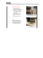
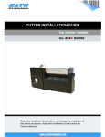
1
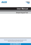
RFID KIT INSTALLATION GUIDE For printer models: GL 4XXe Series For printer models: Read this Installation Guide before and during the installation of the above accessory. Keep this Installation Guide handy for future reference. 1 1 General 1.1 Important information This quick guide provides important information on how to setup your new SATO product. Be sure to read this quick guide thoroughly before using this printer. It is an integral part of the product and should be kept in the immediate vicinity of the device and available to the operating staff. 1.2 Limitation of liability All information in this manual have been compiled under due consideration of federal standards and regulations. The manufacturer will not be held liable for damage resulting from: z Disregarding these instructions z Unintended use of the printer z Unauthorized technical modifications z Use of unapproved spare parts z Use of unapproved consumables FCC WARNING Changes or modifications not expressly approved by the party responsible for compliance could void the user’s authority to operate the equipment. NOTICE This equipment has been tested and found to comply with the limits for a Class B digital device, pursuant to part 15 of the FCC Rules. These limits are designed to provide reasonable protection against harmful interference in a residential installation. This equipment generates, uses and can radiate radio frequency energy and, if not installed and used in accordance with the instructions, may cause harmful interference to radio communications. However, there is no guarantee that interference will not occur in a particular installation. 2 1.3 Explanation of symbols This instruction manual uses various warning icons to help you understand the safe operation of your printer. Explanations of the icons are below. WARNING! Indicates neglectful or erroneous use may cause irreparable damage to the product, serious injury to the operator, or worse. CAUTION! Indicates a specific point where caution should be used. The graphic within the triangle will indicate the specific issue, i.e.; the sign on the left indicates a caution for potential electrical shock. CAUTION! Indicates a potentially hazardous situation which, if not avoided, may result in damage to your product or host equipment. NOTE! Emphasizes useful tips or recommendations for efficient and smooth operation of your printer. 3 1.4 Contact and Document Information SATO GROUP OF COMPANIES . International Headquarters Americas SATO INTERNATIONAL PTE. LTD 438A Alexandra Road #05-01/04, Alexandra Technopark, Singapore 119967 Phone: 65-6271-2122 Fax : 65-6271-2151 Email: [email protected] SATO INTERNATIONAL AMERICA, INC. (Regional HQ) 10350 Nations Ford Road Suite A, Charlotte, NC 28273 Phone: 1-704-644-1650 Fax: 1-704-644-1662 Email: [email protected] Americas SATO LABELING SOLUTIONS AMERICA, INC. 1140 Windham Parkway, Romeoville, Illinois 60446 Phone: 630-771-4200 Fax : 630-771-4210 Email: [email protected] SATO AMERICA, INC. 10350 Nations Ford Road Suite A, Charlotte, NC 28273 Phone: 1-704-644-1650 Fax: 1-704-644-1662 Email: [email protected] Horticultural Division 930 Jimmy Ann Drive Daytona Beach, FL 32117 Phone: 1-386-274-5566 Fax: 1-386-274-5599 Europe SATO INTERNATIONAL EUROPE N.V. (Regional HQ) Leuvensesteenweg 369, 1932 Sint-Stevens-Woluwe, Brussels, Belgium Phone: 32(0)-2-788-80-00 Fax: 32(0)-2-788-80-80 Email: [email protected] SATO UK LTD Valley Road, Harwich, Essex England Co12 4RR, United Kingdom Phone: 44-1255-240000 Fax : 44-1255-240111 Email : [email protected] SATO LABELLING SOLUTIONS EUROPE GmbH Ersheimer Straße 71, 69434 Hirschhorn, Germany Phone: 49-6272-9201-324 Fax: 49-6272-9201-399 SATO POLSKA SP Z O.O. Ul. Wroclawska 123, 55-015 Radwanice K/Wroclawia, Poland Phone: 48-71-381-03-60 Fax: 48-71-381-03-68 Email: [email protected] SATO FRANCE SAS Parc D'Activities - Rue Jacques Messager - 59175 Templemars, France Phone: 33-3-20-62-96-40 Fax: 33-3-20-62-96-55 SATO IBERIA S.A. Dels Corrals Nous, 35-39, Pol. Can Roqueta, 08202 - Sabadell, Barcelona, Spain Phone: 34-93-492-5750 Fax : 34-93-786-3451 Asia Pacific & Oceania SATO INTERNATIONAL ASIA PACIFIC PTE. LTD. (Regional HQ) 438A Alexandra Road #05-01/04, Alexandra Technopark, Singapore 119967 Phone : 65-6271-5300 Fax : 65-6273-6011 Email: [email protected] SATO AUTO-ID MALAYSIA SDN. BHD. No.25, Jalan Pemberita U1/49, Temasya Industrial Park Section U1, 40150 Shah Alam, Selangor Darul Ehsan, Malaysia Phone: 60-3-7620-8901 Fax: 60-3-5569-4977 Email: [email protected] SATO ASIA PACIFIC PTE. LTD. 438A Alexandra Road #05-01/04, Alexandra Technopark, Singapore 119967 Phone: 65-6271-5300 Fax: 65-6273-6011 Email: [email protected] SATO AUTO-ID (THAILAND) CO., LTD. 292/1 Moo 1 Theparak Road, Tumbol Theparak, Amphur Muang, Samutprakarn 10270 Phone: 662-736-4460 Fax: 662-736-4461 SATO SHANGHAI CO., LTD. 307 Haining Road, ACE Bldg, 10th Floor, Hongkou Area, Shanghai, China 200080 Phone: (86) 021- 63068899 Fax: (86) 021- 63091318 SATO AUSTRALIA PTY LTD. 1/1 Nursery Avenue, Clayton Business Park (1508 Centre Road) Clayton VIC 3168, Melbourne, Australia Phone: 61-3-8814-5330 Fax: 61-3-8814-5335 SATO NEW ZEALAND LTD 30 Apollo Drive, Mairangi Bay PO Box 305-031, North Shore, Auckland, New Zealand Phone: 64-9-477-2222 Fax: 64-9-477-2228 For a full list of all SATO offices, refer to www.satoworldwide.com Extensive contact information of worldwide SATO operations can be found on the Internet at www.satoworldwide.com Version: SI-GL4xxe-01rA-12-06-07-RFKIG © Copyright 1994 – 2007 All rights reserved. No part of this document may be reproduced or issued to third parties in any form whatsoever without the express permission of SATO. The materials in this document are provided for general information and are subject to change without notice. SATO assumes no responsibilities for any errors that may appear. 4 GL4xxe RFID KIT Installation The complete RFID kit for the GL consists of five (5) parts: Four parts from the main RFID kit and one part containing the RFID Reader module from AWID. All five parts must be available before installation. Installation involves five (5) steps: Removing the covers; removing the print head; installing the antenna and Reader, and general reassembly. Step Instructions & Tools Image(s) Main RFID Kit Parts List Y9812220001 GL RFID Kit (w/o reader), KIT, RFID, 915, GL4 Or Y9812220001 GL RFID Kit (w/o reader), KIT, RFID, 869, GL4 Or Y9812220001 GL RFID Kit (w/o reader), RFID, 910 914-KOREA, GL4 Each kit consists of the following four parts: 1. 1 MOUNTING READER MOUNT SUBASSEMBLY, GL4 2. ANTENNA ANTENNA ASSY, RFID, GL4 3. CABLE CABLE ASSY, RFID INTERFACE, GL 4. SCREWS SCREW, M4 X 8, PNH, PHH, STL/ZN PL SCREW, 6-19 HL X 1/2, PHCR, SS410, ANSI B18.6.4 Figure 1a. The RFID Kit (w/o reader subassembly) before unpacking Figure 1b. The RFID Reader module RFID Reader Module Kit This kit comes from AWID and supplies the fifth and final part of the complete RFID Kit for the GL4xxe. See the picture on the right for details of region configurations. Three configurations are available: MPR-1510-V2.6H (USA configuration) MPR-1510-V2.6HR1 (EU configuration) MPR-1510-V2.6H2 (Korea configuration) 5 Removing the front cover Tool(s) required Flat blade screwdriver (recommended) 1. Loosen and remove the thumbscrew fastener that secures the front cover. Figure 1a. Removing the thumbscrew 1 2. Pull the outer edge of the front cover outwards, and then push the entire cover in the direction shown by the arrow. The cover will be dislodged. 3. Put the cover and thumbscrew aside. Figure 1b. Pulling out the front cover Note: Do not use force when removing the front cover as this can potentially damage the plastic holding pins on the cover. Removing the LEFT Side Cover Figure 1c. The LEFT side cover Tool(s) required #1 Phillips + screwdriver 1. Remove three screws (see red circles in the picture) that secure the cover. 2. Slide the cover towards the rear of the printer for about an inch, and then lift the cover up to remove it from unit (refer to the red arrows in the picture). 3. Place the cover and three screws aside for now. Figure 1d. Side cover removed 6 Removing the Print Head 2 1. Release the print head assembly by turning the head lock latch counterclockwise. 2. Press the spring-loaded tab as indicated here, to release the print head. 3. Disconnect the data and power cables from the print head. 4. Figure 2a. Turning the head lock latch Set the print head aside for now. Note: ESD (electrostatic discharge) protection is recommended for this step. Anti-static lint-free gloves should be worn at all times when you are handling print heads. Figure 2b. Print head removed 7 Installing the antenna Part(s) Required ANTENNA ASSY, RFID, SL4M SCREW, 6-19 HL X 1/2, PHCR, SS410, ANSI B18.6.4 Tool(s) required #1 Phillips + screwdriver - 12 in. lb 1. Remove the gap sensor paddle (circled red) by sliding it out. Set the gap sensor paddle aside for later use. 2. Remove the media guard (circled yellow) that is under the gap sensor, by removing the associated screw (circled blue). (Figure 3a) 3. The antenna handle replaces the removed media guard, and will be secured by the same screw (circled blue in Fig 3d). Install the screw through the lower support hole and into the antenna handle as shown. 5. Tighten the screw to secure the antenna handle in place. 6. Re-install the gap sensor paddle. 7. Re-install the print head assembly. 3 antenna handle Hook the purple catch of the antenna handle over the rod (circled blue) situated behind the black platen roller. The cable should emerge at the bottom of the printer. See Figures 3a and 3b. 4. Figure 3a. Removing the gap sensor paddle (red) and media guard (yellow) purple catch Figure 3b. Hook the antenna handle over the metal rod that is behind the platen roller. Note ESD (electrostatic discharge) protection is recommended for this step. Anti-static lint-free gloves are recommended to be worn at all times when handling the print head. The gap sensor paddle will be re-installed in the final step. The original media guard must be set aside and sent back to your supplier for recycling. Figure 3c. The antenna emerges as shown. Figure 3c. Securing the antenna handle with the screw. 8 Assembling the Reader Module Antenna cable Parts required READER MOUNT SUBASSEMBLY, GL4xxe Tool(s) required #1 Phillips + screwdriver - 8 in. lb. 1. Plug the antenna cable into the port on the right side of the Reader Subassembly as indicated in Figure 4a. Figure 4a. Ports on the Reader Subassembly. 2. Route the other end of the cable into the electronics section of the printer. The cable connects to the white connector on the printer’s main PCB, near the moto. See Figure 4c. 3. Position the reader subassembly within the lower part of the print head area. while pulling any excess length of interface cable slack back into the electronics side of the printer. 4 Figure 4b. Insert the reader as shown 4. Attach the reader subassembly to the printer with the supplied screw (circled red in Figure 4b). 5. Tighten and torque the screw. 6. Close and latch the deck assembly. 7. Position the antenna handle above the printed orangecolored marker’s location for testing. Figure 4c. Insert the connector as shown Note When installing the reader subassembly, make sure that the antenna or power/data cables are not crimped by any moving part within the mounting area. 9 Reassembly Tools required #1 Phillips + screwdriver - 8 in. lb. 1. Pull any slack interface cable slack back into the electronics compartment of the printer. 2. Put back the side cover that was removed in Step 3 (page 6). 3. Tighten and torque screws. 4. Put back the front cover that was removed in Step 2. 5. Re-install the gap sensor paddle in the reverse order of removal. 6. Close the media cover. 5 Setting the Country Frequency When the RFID kit is installed, the printer will automatically be set to use the Country Frequency of the antenna module. However, if the error message “RFID Freq BandL /Unknown” appears, see below: 1. If the RFID Freq Band: / Unknown message appears after the printer reboots, go to step 4. 2. Press the Up, Down, Left, and Right keys at the same time to access the factory Menus. 3. Press the Up key until RFID Freq Band displays. 4. Press the Down and ENTER key at the same time until the message ENTER SWITCH UNLOCKED is displayed. Table 1. Country/Frequency Selection 5. 6. 7. Country Menu Item Frequency (MHz) Hong Kong 920-925 H.Kong 920 to 925 Taiwan Taiwan 7 923.6 to 926.5 United States/Canada 902-928 US 1 902 to 928 Press the Left or Right key until the correct menu item for your country displays. See Table 1. Press ENTER to select the frequency. Turn the printer OFF and then ON to restart it. 10 11