1
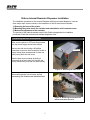
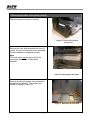
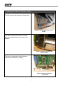
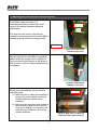
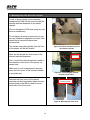
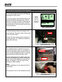
INTERNAL REWINDER-DISPENSER INSTALLATION GUIDE
For printer models:
GL 4xxe Series
Read this Installation Guide before and during the installation
of the above accessory. Keep this Installation Guide handy for
future reference.
1 General
1.1 Important information
This quick guide provides important information on how to setup your new
SATO product.
Be sure to read this quick guide thoroughly before using this printer. It is
an integral part of the product and should be kept in the immediate vicinity
of the device and available to the operating staff.
1.2 Limitation of liability
All information in this manual have been compiled under due
consideration of federal standards and regulations.
The manufacturer will not be held liable for damage resulting from:
z Disregarding these instructions
z Unintended use of the printer
z Unauthorized technical modifications
z Use of unapproved spare parts
z Use of unapproved consumables
FCC WARNING
Changes or modifications not expressly approved by the party responsible for
compliance could void the user’s authority to operate the equipment.
NOTICE
This equipment has been tested and found to comply with the limits for a
Class B digital device, pursuant to part 15 of the FCC Rules. These limits
are designed to provide reasonable protection against harmful interference
in a residential installation.
This equipment generates, uses and can radiate radio frequency energy
and, if not installed and used in accordance with the instructions, may cause
harmful interference to radio communications. However, there is no
guarantee that interference will not occur in a particular installation.
2
1.3 Explanation of symbols
This instruction manual uses various warning icons to help you
understand the safe operation of your printer. Explanations of the icons
are below.
WARNING!
Indicates neglectful or erroneous use may cause
irreparable damage to the product, serious injury to the
operator, or worse.
CAUTION!
Indicates a specific point where caution should be used.
The graphic within the triangle will indicate the specific
issue, i.e.; the sign on the left indicates a caution for
potential electrical shock.
CAUTION!
Indicates a potentially hazardous situation which, if
not avoided, may result in damage to your product
or host equipment.
NOTE!
Emphasizes useful tips or recommendations for
efficient and smooth operation of your printer.
3
1.4
Contact and Document Information
SATO GROUP OF COMPANIES
.
International Headquarters
Americas
SATO INTERNATIONAL PTE. LTD
438A Alexandra Road #05-01/04,
Alexandra Technopark, Singapore 119967
Phone: 65-6271-2122 Fax : 65-6271-2151
Email: [email protected]
SATO INTERNATIONAL AMERICA, INC.
(Regional HQ)
10350 Nations Ford Road Suite A,
Charlotte, NC 28273
Phone: 1-704-644-1650 Fax: 1-704-644-1662
Email: [email protected]
Americas
SATO AMERICA, INC.
10350 Nations Ford Road Suite A,
Charlotte, NC 28273
Phone: 1-704-644-1650 Fax: 1-704-644-1662
Email: [email protected]
SATO LABELING SOLUTIONS AMERICA, INC.
1140 Windham Parkway, Romeoville, Illinois 60446
Phone: 630-771-4200 Fax : 630-771-4210
Email: [email protected]
Horticultural Division
930 Jimmy Ann Drive
Daytona Beach, FL 32117
Phone: 1-386-274-5566 Fax: 1-386-274-5599
Europe
SATO INTERNATIONAL EUROPE N.V.
(Regional HQ)
Leuvensesteenweg 369, 1932 Sint-Stevens-Woluwe, Brussels, Belgium
Phone: 32(0)-2-788-80-00 Fax: 32(0)-2-788-80-80
Email: [email protected]
SATO UK LTD
Valley Road, Harwich, Essex England Co12 4RR,
United Kingdom
Phone: 44-1255-240000 Fax : 44-1255-240111
Email : [email protected]
SATO LABELLING SOLUTIONS EUROPE GmbH
Ersheimer Straße 71,
69434 Hirschhorn, Germany
Phone: 49-6272-9201-324 Fax: 49-6272-9201-399
SATO POLSKA SP Z O.O.
Ul. Wroclawska 123, 55-015 Radwanice
K/Wroclawia, Poland
Phone: 48-71-381-03-60 Fax: 48-71-381-03-68
Email: [email protected]
SATO FRANCE SAS
Parc D'Activities - Rue Jacques Messager - 59175 Templemars, France
Phone: 33-3-20-62-96-40 Fax: 33-3-20-62-96-55
SATO IBERIA S.A.
Dels Corrals Nous, 35-39, Pol. Can Roqueta,
08202 - Sabadell, Barcelona, Spain
Phone: 34-93-492-5750 Fax : 34-93-786-3451
Asia Pacific & Oceania
SATO INTERNATIONAL ASIA PACIFIC PTE. LTD.
(Regional HQ)
438A Alexandra Road #05-01/04,
Alexandra Technopark, Singapore 119967
Phone : 65-6271-5300 Fax : 65-6273-6011
Email: [email protected]
SATO AUTO-ID MALAYSIA SDN. BHD.
No.25, Jalan Pemberita U1/49, Temasya
Industrial Park
Section U1, 40150 Shah Alam,
Selangor Darul Ehsan, Malaysia
Phone: 60-3-7620-8901 Fax: 60-3-5569-4977
Email: [email protected]
SATO ASIA PACIFIC PTE. LTD.
438A Alexandra Road #05-01/04, Alexandra Technopark, Singapore 119967
Phone: 65-6271-5300 Fax: 65-6273-6011
Email: [email protected]
SATO AUTO-ID (THAILAND) CO., LTD.
292/1 Moo 1 Theparak Road, Tumbol Theparak,
Amphur Muang, Samutprakarn 10270
Phone: 662-736-4460 Fax: 662-736-4461
SATO SHANGHAI CO., LTD.
307 Haining Road, ACE Bldg, 10th Floor,
Hongkou Area,
Shanghai, China 200080
Phone: (86) 021- 63068899 Fax: (86) 021- 63091318
SATO AUSTRALIA PTY LTD.
1/1 Nursery Avenue, Clayton Business Park (1508 Centre Road) Clayton
VIC 3168, Melbourne, Australia
Phone: 61-3-8814-5330 Fax: 61-3-8814-5335
SATO NEW ZEALAND LTD
30 Apollo Drive, Mairangi Bay
PO Box 305-031, North Shore, Auckland, New Zealand
Phone: 64-9-477-2222 Fax: 64-9-477-2228
For a full list of all SATO offices,
refer to www.satoworldwide.com
Extensive contact information of worldwide SATO operations can be found on the Internet at
www.satoworldwide.com
Version: SI-GL4xxe-01rA-05-06-07-IRWIG © Copyright 1994 – 2007
All rights reserved. No part of this document may be reproduced or issued to third
parties in any form whatsoever without the express permission of SATO. The materials
in this document are provided for general information and are subject to change without notice. SATO
assumes no responsibilities for any errors that may appear.
4
GL4xxe Internal Rewinder-Dispenser Installation
The installation procedure for the Internal Rewinder with front-mounted dispenser, involves
three major steps, that are similar to the installation of the GL4xxe internal rewinder:
1) Removing the base of the printer.
2) Mounting the printer above the rewinder and reinstallation of all removed covers.
3) Mechanical adjustment of the rewinder.
The pictures of the internal-rewinder used in this Guide are applicable for installation
processes of both the rewinder and rewinder-dispenser units.
1) Removing the base of the printer
Make sure the printer is OFF and disconnected
from the power supply and all other cables.
Remove the side cover using a #2 phillips
screwdriver to remove three screws as circled in
orange. Keep these screws aside for later use
when putting back the side cover.
Cover LH
Slide the side cover outwards by sliding it
horizontally by a few inches first (see the red
arrow), before lifting it up and out (white arrow).
Figure 1a. Removing the side cover
Remove the printer’s front cover by first
unscrewing the thumbscrew indicated here.
Figure 1b. Removing the thumbscrew
that secures the front cover.
5
1) Removing the base of the printer (cont’d)
The front cover can now be removed.
Figure 1c. Front cover can now
be removed
Remove the lock shaft located at the front of
printer. (Do not lose this part as it is essential
for the installation of dispenser option)
Note
This lock shaft must be removed for the
successful installation of the internal
rewinder.
Figure 1d. Removing the lock shaft.
Remove a total of 9 screws (cross recessed
hexagonal bolt M4x10). Four screws are
circled in orange in Figure 1d.
Figure 1d. Removing the lock shaft.
6
1) Removing the base of the printer (cont’d)
The fifth screw to be removed is shown here.
Figure 1e. Removing the fifth of nine
screws
The sixth and seventh screws are shown
here, securing the base to the front of the
chassis.
Figure 1f. Removing the sixth and
seventh screws
The last two screws are on the electronic
section as circled here in orange.
Figure 1g. Removing the final
two screws
7
1) Removing the base of the printer (cont’d)
Finally, carefully separate the base plate of
the printer from the main chassis.
This can be done by placing the printer on its
side and pulling the base plate out.
Figure 1h. Separating the base from
the printer
8
2) Mounting the printer above the rewinder-dispenser
To facilitate easier mounting, it is
recommended that you remove the front
cover of the internal rewinder-dispenser
beforehand.
Front cover
フロントカバー
Pull down the side cover of the internal
rewinder and remove two bind screws (M4x4)
located as shown within the orange circles.
図
Side cover
Figure 2a. Removing the
rewinder’s front cover
Remove two bind screws (M4x4) located as
shown within the orange circles. Slightly lift
the front cover in the direction of the arrow a
little at a time, until it is totally separated from
the chassis.
Figure 2b. Removing the
rewinder’s front cover
Mount the printer chassis onto the internal
rewinder gently.
Sensor cable
a) Make sure that no cables are sandwiched
between the printer chassis and internal
rewinder-dispenser chassis during
installation.
b) Make sure that the sensor cable located at
the left bottom of platen roller at the front
of the printer (Fig 2c), is not caught in the
bracket during installation of the internal
rewinder-dispenser.
Figure 2c. Make sure no cables are
compressed during the mounting.
9
1) Mounting the printer above the rewinder
A total of seven screws (cross recessed
hexagonal bolt M4x10) are used to install the
internal rewinder-dispenser to the printer
chassis
(Do not damage the PCB when using any tool
such as screwdriver)
Do not tighten all seven screws until you are
sure the installation alignment is correct. Also
check that all connectors have been
reconnected.
Two screws removed originally from the front
of the printer, will be left unused.
Figure 2d. Printer mounted on top of
the internal rewinder
Next, we will reinstall the front cover of the
internal rewinder-dispenser.
Connector
コネクター
First, connect the internal rewinder’s cable to
the connector at the front of the printer, as
shown here.
Make sure it is not compressed in any way
when the front cover of the internal rewinder
is mounted next.
Figure 2e. Connecting the internal
rewinder signal cable
Reinstall the front cover of the internal
rewinder and and temporarily tighten the two
screws (bind screw M4×4) used to secure
each side of the front cover.
Four screws to be
secured in total
Figure 2f. Mounting the front cover
10
1) Mounting the printer above the rewinder (cont’d)
If the front cover snaps into place correctly,
you can proceed to further tighten the screws
permanently, followed by inserting the
thumbscrew used to secure the printer’s front
cover in the first step of this guide.
Figure 2g. Installing the
thumbscrew
Finally, connect the printer power cable as
shown, routing it through the slot at the
bottom of the internal rewinder.
Figure 2h. Plugging the
power cable
11
3) Mechanical adjustment of the dispenser
Turn the printer ON and take it OFFLINE (by
pressing the LINE button).
ADVANCED MODE
Go into the printer’s ADVANCED Mode and
scroll to the Media Handling menu. Select
Peel-Off to activate the peel-off and rewinder
functions, and then exit the menu. Perform
some printing to test the proper functioning of
the liner rewinder.
Use the
Media
Handling
menu to
activate the
rewinder
Peel-Off
Figure 3a. Advanced Mode
Media Handling menu
Load the label and ribbon according to the
route drawing. The printer starts printing once
it is at test print mode.
Liner
Check if the liner winding path meanders to
the left and right. If so, adjust the dispenser
plate. See next step.
Figure 3b. Checking the liner winding
path for meandering
The dispenser plate is adjusted via the the
screw of the ‘adjust collar’: turn clockwise to
move the dispenser plate forward toward you.
Turn counter-clockwise direction to move the
dispenser plate toward the printer itself.
Perform adjustment of the adjust collar and
checki the meandering condition during test
prints. Repeat the adjustment until the liner
does not meander to left and right during
feeding and back-feeding.
Dispenser
Adjust collar
Note
If ribbon wrinkling occurs, adjust the ribbon
adjust plate.
This marks the end of the installation process.
Figure 3c. Adjusting liner meandering
via the adjust collar.
12
13